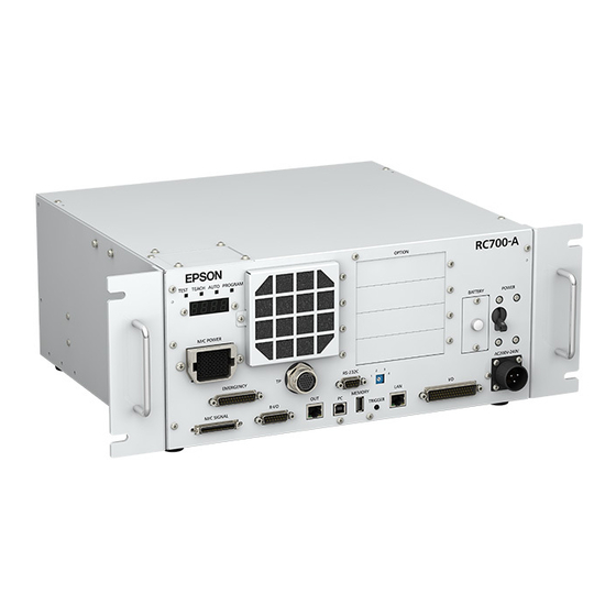
Epson RC700 Manual

Epson RC700 Manual

Robot controller option teach pendant
Hide thumbs Also See for RC700:
Table of Contents

Advertisement

Quick Links

Robot Controller
RC700 / RC90 Option
Teach Pendant
TP2
Rev.11
EM198P4025F

Advertisement

Table of Contents
loading

Summary of Contents for Epson RC700

  • Page 1 Robot Controller RC700 / RC90 Option Teach Pendant Rev.11 EM198P4025F...
  • Page 3 Robot Controller RC700 / RC90 Option Teach Pendant Rev.11 Copyright © 2012-2019 SEIKO EPSON CORPORATION. All rights reserved. RC700 / RC90 option TP2 Rev.11...
  • Page 4 3. We cannot foresee all possible dangers and consequences. Therefore, this manual cannot warn the user of all possible hazards. RC700 / RC90 option TP2 Rev.11...
  • Page 5 Please notify us if you should find any errors in this manual or if you have any comments regarding its contents. MANUFACTURER CONTACT INFORMATION Contact information is described in “SUPPLIERS” in the first pages of the following manual: Robot System Safety and Installation Read this manual first RC700 / RC90 option TP2 Rev.11...
  • Page 6 Operation of RC700 / RC90 (EPSON RC+7.0) option TP2 deviates from the descriptions NOTE  in this manual when it is connected to the Robot Controller RC90 (EPSON RC+5.0) or RC180. In this case, refer to the following manual. RC90 / RC180 option Teach Pendant TP2 Manual A coordinate point including the arm pose is defined as “position (point),”...
  • Page 7 TYPE C: Manipulator Software T series EPSON RC+ 7.0 Ver.7.3.1 or later When using the Robot Controller RC90 without the label (EPSON RC+ 5.0) or RC180, NOTE  refer to the . Functions are different RC90 / RC180 option Teach Pendant TP2 manual from the descriptions in this manual.
  • Page 8 For T series, VT series Manipulator user only T series and VT series Manipulators are Controller integrated Manipulators. Read “Controller” and “Robot Controller” described in this manual as “T series Manipulator” “VT series Manipulator”. RC700 / RC90 option TP2 Rev.11...
  • Page 9: Table Of Contents

    4.2 Switch Operation Mode ................16 5. Operation Panel (Key Description) 5.1 Key Description .................... 17 Number Input Keys ..................17 Teaching Keys ....................17 Arrow Keys ....................18 Function Keys .....................18 Jog Keys .....................18 Other keys ....................18 Lamp 19 RC700 / RC90 option TP2 Rev.11...
  • Page 10 2.2 [Direct Teach + Touch Jog] ................. 44 2.2.1 Switch to [Direct Teach + Touch Jog] screen ......... 45 2.2.2 Switch the Display ................48 2.2.3 Resetting Error ................49 2.2.4 Motor ON / OFF ................49 viii RC700 / RC90 option TP2 Rev.11...
  • Page 11 2.6.2 Servo Free for Each Joint ...............84 2.6.3 Servo Free for J7, J8, and J9 ............84 2.6.4 Servo Free for All Joints ..............85 2.7 Brake ......................86 2.7.1 Turn the brake ON ................86 2.7.2 Turn the brake OFF .................86 RC700 / RC90 option TP2 Rev.11...
  • Page 12 Robot does not move by pressing the Jog key ..........106 Operation mode does not switch from TEACH mode to AUTO mode ....106 Robot motion will is slow after switching the mode from TEACH to AUTO ..106 5. Maintenance Parts List RC700 / RC90 option TP2 Rev.11...
  • Page 13: Functions & Installation

    Functions & Installation This section contains information about functions and installation of the Teach Pendant to be known before operation and maintenance.
  • Page 15: Safety

    The personnel who have taken the safety training acquire knowledge of industrial robots (operations, teaching, etc.). The personnel who have completed the robot system-training class held by the manufacturer, dealer, or locally-incorporated company are allowed to maintain the robot system. RC700 / RC90 option TP2 Rev.11...
  • Page 16 Damaged cables, disconnection, or contact failure is extremely WARNING hazardous and may result in electric shock and/or improper function of the system. Do not use the cables near heat or fire. RC700 / RC90 option TP2 Rev.11...
  • Page 17: Safety-Related Requirements

    Industrial, scientific and medical (ISM) radio-frequency equipment -- Electromagnetic CISPR11 disturbance characteristics -- Limits and methods of measurement EN 55011 Electromagnetic compatibility (EMC) -- Part 6-2: Generic standards -- Immunity for IEC 61000-6-2 industrial environments EN 61000-6-2 RC700 / RC90 option TP2 Rev.11...
  • Page 18: Emergency Stop

    (3) Turn the Teach Pendant mode selector key switch to “Teach”. Press the <Reset> key on the operation panel to reset the Emergency Stop. Make sure that the E-Stop lamp on the operation panel is OFF. E-Stop lamp <Reset> key RC700 / RC90 option TP2 Rev.11...
  • Page 19: Mode Selector Key Switch

    Mode switching during task execution AUTO → TEACH (1) Press the <Stop> button of EPSON RC+ to stop all tasks normally. (2) Turn the mode selector key switch to “Teach”. TEACH → AUTO Turn the mode selector key switch to “Auto”...
  • Page 20: Specifications

    Functions & Installation 2. Specifications 2. Specifications 2.1 Part Names and Functions RC700 / RC90 option TP2 Rev.11...
  • Page 21: Standard Specifications

    Approx. 400 g or less (excluding cables) Display element STN type Reflective black and white LCD Display 0 to 60 Contrast specifications Back light 0 to 255 Serial interface Electrical characteristics Compliant with RS-422A standard specifications RC700 / RC90 option TP2 Rev.11...
  • Page 22: Outer Dimensions

    Functions & Installation 2. Specifications 2.3 Outer Dimensions RC700 / RC90 option TP2 Rev.11...
  • Page 23: Installation

    The surface of the buttons may be damaged as they are easily scratched.  Wipe the dirt and oils adhering to the surface of the Teach Pendant display with a soft cloth dampened with a neutral detergent or an alcohol solvent. RC700 / RC90 option TP2 Rev.11...
  • Page 24: Connection

    Operation of RC700 / RC90 (EPSON RC+ 7.0) option TP2 deviates from the descriptions NOTE  in this manual when it is connected to the Robot Controller RC90 (EPSON RC+ 5.0) or RC180. In this case, refer to the following manuals.
  • Page 25: Connection To The Controller

    After the completing the Controller and the Teach Pendant communication, the following screen will appear on the display of the Teach Pendant. TEACH mode 01 000 LWM T00A00 ■ X : 0150.000 Y : 0150.000 Z :-0050.000 AUTO mode Auto Ready RC700 / RC90 option TP2 Rev.11...
  • Page 26: Operation Mode (Teach, Auto)

    Push the jog key to move the robot. Direct Teach + Touch Jog operations: Move the robot directly. Use EPSON RC+ 7.0 Option Force Guide 7.0. AUTO mode This mode enables automatic operation (program execution) of the Robot system at the manufacture operation, besides, programming, debug, adjustment, and maintenance of the Robot system.
  • Page 27 When not using the Force Guide 7.0, the impedance tester is not available. NOTE  * Direct Teach + Touch Jog function is supported as default for EPSON RC+ 7.0 Ver.7.4.4 or later. However, Direct Teach + Touch Jog function is available only when using EPSON RC+ 7.0 Option Force Guide 7.0.
  • Page 28: Switch Operation Mode

    “TEACH”. NOTE  To switch the mode from TEACH to AUTO, the latch release input is required. For the latch release, refer to Robot Controller manual: Latch Release Switch. RC700 / RC90 option TP2 Rev.11...
  • Page 29: Operation Panel (Key Description)

    Speed Specifies the Jog speed Mode Specifies the Jog mode Dist Specifies the Jog distance Reset Sets the initial setup status Motor Switches the motor power ON/OFF Home Moves the robot to home position RC700 / RC90 option TP2 Rev.11...
  • Page 30: Arrow Keys

    Cancel Cancels the setting and goes back to the previous screen Saves the setting and changes to the next screen Page Up Changes to the previous page Page Down Changes to the next page RC700 / RC90 option TP2 Rev.11...
  • Page 31: Lamp

    If you pull harder, or let go, then the switch will be disengaged and the operation will be canceled. Enable Switch 7. Warning Sound (Beep) The Teach Pendant beeps when the robot passes the singularity. RC700 / RC90 option TP2 Rev.11...
  • Page 32 Functions & Installation 7. Warning Sound (Beep) RC700 / RC90 option TP2 Rev.11...
  • Page 33 Operation This section contains information about operation of the Teach Pendant and maintenance procedure.
  • Page 35: Teaching Procedure

    6-Axis robots (C4 series, C8 series, N series): Direct Teach + Touch Jog operation is available. Use EPSON RC+7.0 Option Force Guide 7.0 to move the robot arm directly in the [Direct Teach + Touch Jog] screen. NOTE ...
  • Page 36: Jog Operation

    (1) Press the <Dist> key to select “C” for the Jog Distance in the [Jog & Teach] screen. 01 000 LWC T00A00 ■ (2) Execute the continuous jog by gripping the enable switch as pressing the Jog key. (3) Move the robot to the teaching position. RC700 / RC90 option TP2 Rev.11...
  • Page 37: Direct Teaching Operation (Scara, Rs Series Robots)

    (3) Move the robot arm to the teaching position manually. 1.3 Direct Teach + Touch Jog Operation (C4, C8, N series robots) In [Direct Teach + Touch Jog] screen, use EPSON RC+7.0 Option Force Guide 7.0 to move the robot directly by hands.
  • Page 38 While the Direct Teach or Touch Jog is operating, “Executing…” is displayed on the header and any key operations of TP2 is disabled. To perform point teaching or change parameters, release the hand from the enable switch. RC700 / RC90 option TP2 Rev.11...
  • Page 39: Teaching Operation

    In the [SavePoints] screen, if you press the <Cancel> key, it does not save the file and NOTE  returns to the [Jog & Teach] screen or the [Direct Teach + Touch Jog] screen. RC700 / RC90 option TP2 Rev.11...
  • Page 40: Teach Mode

    “point data.” NOTE  * The impedance tester is supported as standard for EPSON RC+ 7.0 Ver. 7.2.0 or later. However, the impedance tester is available only when using the EPSON RC+ 7.0 option Force Guide 7.0. When not using the Force Guide 7.0, the impedance tester is not available.
  • Page 41: Jog & Teach

    Switches to Tool number input mode. Switches to Arm number input mode. User Dist Switches to User Dist number input mode. Guide Displays the key operation guide. Page Up / Down Changes to the previous or next page. RC700 / RC90 option TP2 Rev.11...
  • Page 42 Switches between U, V, and W jog keys and R, S, and T jog keys. (When the ECP option is enabled.) Switches to ECP number input mode. Changes to the point number input mode. RC700 / RC90 option TP2 Rev.11...
  • Page 43: Current Position Display

    S : 0000.000 Hand : Righty T : 0000.000 Page 4 01 000 LWM T00 *■ Hand : Righty Elbow: Above Wrist: NoFlip Page 5 01 000 LWM T00 *■ J1lag: 0 J4lag: 0 J6Flag: 000 RC700 / RC90 option TP2 Rev.11...
  • Page 44 01 000 LWM T00A00 *■ 01 000 LWM T00A00 *■ R : 0000.000 Hand : Righty S : 0000.000 J1Flag: 0 T : 0000.000 J2Flag: 0 Page 4 01 000 LWM T00A00 *■ J1Angle : 0000.000 RC700 / RC90 option TP2 Rev.11...
  • Page 45 S : 0000.000 T : 0000.000 Page 4 01 000 LWM T00 *■ Hand : Righty Elbow : Below Wrist : NoFlip Page 5 01 000 LWM T00 *■ J4Flag : 0 J6Flag : 000 RC700 / RC90 option TP2 Rev.11...
  • Page 46: Resetting Error

    Press the OK Key. (2) Holding down the Enable Switch, press the <OK> key to execute a Home operation. (3) When the robot has reached the Home position, it returns to the [Jog & Teach] screen. RC700 / RC90 option TP2 Rev.11...
  • Page 47: Executing Alignment

    L■ Go Align (Here, 01) Hold Enable switch. Press the OK Key. (3) Press the <OK> key while holding the enable switch. End Alignment. When Alignment ends, return to the [Jog & Teach] screen. RC700 / RC90 option TP2 Rev.11...
  • Page 48: Executing Mcal

    For details of the Jog Mode, refer to Operation 2.1.10 Jog Mode. (2) Press the <Dist> key until the Jog Distance turns to ‘S’. 01 000 LJS T00A00 ■ For details of the Jog Mode, refer to Operation 2.1.11 Jog Distance. RC700 / RC90 option TP2 Rev.11...
  • Page 49: Moving The Robot By Rst

    Jogging the additional S and T axes of SCARA, Cartesian, and RS series robots To jog the additional S and T axes of SCARA, Cartesian, and RS series robots, use the V and W jog keys. RC700 / RC90 option TP2 Rev.11...
  • Page 50: Changing Local / Tool / Arm / Ecp

    (3) Press the <OK> key. The Arm number has changed and it returns to the [Jog & Teach] screen. When you press the <Cancel> key, it returns to the [Jog &Teach] screen without  saving the change. RC700 / RC90 option TP2 Rev.11...
  • Page 51: Jog Mode

    Jogs each joint of the robot. Joint Other jog key will appear when using non-Cartesian robots in the “Joint” mode. Jogs the robot along the axes of the coordinate system defined by the current external control point. RC700 / RC90 option TP2 Rev.11...
  • Page 52: Jog Distance

    When you want to move the robot in other distance, use the User jog distance that you can specify desired distance. (1) Press the <User Dist> key in the [Jog & Teach] screen. It turns to the User jog distance input mode. UserDist: 000.000 RC700 / RC90 option TP2 Rev.11...
  • Page 53: Servo Lock And Servo Free

    Overwrite (3) Press the <OK> key. The point data is registered in the memory and it returns to the [Jog & Teach] screen.  This can also be executed in the [Point Editor] screen. RC700 / RC90 option TP2 Rev.11...
  • Page 54: Changing Point Number

    (2) Press the <OK> key to save the point data to the file.  This can also be executed in the [Point Editor] screen. 2.1.17 Loading Point Data from File (1) Press the <Load> key. 01 LoadPoints Robot1.PTS (2) Move the cursor and select a file. RC700 / RC90 option TP2 Rev.11...
  • Page 55: Changing The Robot

    <Cancel> : Does not save the change and loads the point file.  This can also be executed in the [Point Editor] screen. 2.1.18 Changing the Robot You can change the robot to execute Jog & Teach. For details, refer to Operation 2.8 Robot. RC700 / RC90 option TP2 Rev.11...
  • Page 56: Direct Teach + Touch Jog]

    2. TEACH Mode 2.2 [Direct Teach + Touch Jog] To use the Direct Teach or Touch Jog function, some settings are required on EPSON RC+ after installing the force sensor. Perform the following settings before using the Direct Teach or Touch Jog function.
  • Page 57: Switch To [Direct Teach + Touch Jog] Screen

    “0”. Therefore, if the force applied is removed, the Force Sensor detects a force even if no force is applied. If the Direct Teach or Touch Jog function is executed in this state, the robot may move unintentionally. Caution is required in this regard. RC700 / RC90 option TP2 Rev.11...
  • Page 58 Switches to Tool number input mode. Switches to Arm number input mode. User Dist Not in use. Guide Displays the key operation guide. Page Up / Down Changes to the previous or next page. RC700 / RC90 option TP2 Rev.11...
  • Page 59 Changes to the force setting screen. Refer to 2.2.8 Set Direct Teach (Force Setting) Operation Changes to the Touch Jog setting screen. Refer to 2.2.9 Set Touch Jog Operation Changes to the point number input mode. RC700 / RC90 option TP2 Rev.11...
  • Page 60: Switch The Display

    W : 0000.000 Page 3 01 000 FDT T00 R L■ Hand : Righty Elbow: Above Wrist: NoFlip Page 4 01 000 FDT T00 R L■ J1Flag : 0 J4Flag : 0 J6Flag : 000 RC700 / RC90 option TP2 Rev.11...
  • Page 61: Resetting Error

    (2) Holding down the Enable Switch, press the <OK> key to execute a Home operation. (3) When the robot has reached the Home position, it returns to the [Direct Teach + Touch Jog] screen. RC700 / RC90 option TP2 Rev.11...
  • Page 62: Changing Local And Tool

    The Tool number has changed and it returns to the [Direct Teach + Touch Jog] screen. When you press the <Cancel> key, it returns to the [Direct Teach + Touch Jog]  screen without saving the change. RC700 / RC90 option TP2 Rev.11...
  • Page 63: Switch The Function

    For the use of the both functions, refer to the following section: Touch 2.2.15 Execute Direct Teach or Touch Jog Operation Direct Use Direct Teach function only. Teach Touch Use Touch Jog function only. RC700 / RC90 option TP2 Rev.11...
  • Page 64: Set Direct Teach (Force Setting)

    Fix the changes and rerun to the [Direct Teach + Touch Jog] screen. Cancel Cancel the changes and rerun to the [Direct Teach + Touch Jog] screen. Return to the [Direct Teach + Touch Jog] screen. RC700 / RC90 option TP2 Rev.11...
  • Page 65 Return to the [Direct Teach + Touch Jog] screen without updating the the Direct Teach settings. Set other parameters of Direct Teach settings: Use ▲ / ▼ key to move the cursor to the other parameter. RC700 / RC90 option TP2 Rev.11...
  • Page 66 (3) Use ▲ / ▼ key to move the cursor to “ Detail”. Detail: Move & Rotate (4) Use  /  key to set the details of the motion direction. Display changes depending on the motion direction selected in “Direction”. RC700 / RC90 option TP2 Rev.11...
  • Page 67 Return to the [Direct Teach + Touch Jog] screen without updating the the Direct Teach settings. Set other parameters of Direct Teach settings: Use ▲ / ▼ key to move the cursor to the other parameter. RC700 / RC90 option TP2 Rev.11...
  • Page 68: Set Touch Jog

    Fix the changes and rerun to the [Direct Teach + Touch Jog] screen. Cancel Cancel the changes and rerun to the [Direct Teach + Touch Jog] screen. Return to the [Direct Teach + Touch Jog] screen. RC700 / RC90 option TP2 Rev.11...
  • Page 69 Return to the [Direct Teach + Touch Jog] screen without updating the the Direct Teach settings. Set other parameters of Direct Teach settings: Use ▲ / ▼ key to move the cursor to the other parameter. RC700 / RC90 option TP2 Rev.11...
  • Page 70 Return to the [Direct Teach + Touch Jog] screen without updating the the Direct Teach settings. Set other parameters of Direct Teach settings: Use ▲ / ▼ key to move the cursor to the other parameter. RC700 / RC90 option TP2 Rev.11...
  • Page 71 Return to the [Direct Teach + Touch Jog] screen without updating the the Direct Teach settings. Set other parameters of Direct Teach settings: Use ▲ / ▼ key to move the cursor to the other parameter. RC700 / RC90 option TP2 Rev.11...
  • Page 72: Reset Force Sensor

    2. TEACH Mode 2.2.10 Reset Force Sensor Epson’s Force Sensors have a drift characteristic. Therefore, if a time passes, the sensor may move even if the force is not applied to it when executing the Direct Teach or Touch Jog due to the drift errors.
  • Page 73: Changing Point Number

    The point data is registered to the memory and return to the [Touch Jog + Direct Teach] screen. Do not save position information: Press the <Cancel> key. Return to the [Touch Jog + Direct Teach] screen.  This can also be executed in the [Point Editor] screen. RC700 / RC90 option TP2 Rev.11...
  • Page 74: Saving Point Data To File

    Press the <OK> key to save the point data to the file.  This can also be executed in the [Point Editor] screen. 2.2.14 Loading Point Data from File (1) Press the <Load> key. 01 LoadPoints Robot1.PTS (2) Move the cursor to select a file. RC700 / RC90 option TP2 Rev.11...
  • Page 75: Execute Direct Teach Or Touch Jog

    Switches the Jog Distance for Touch Jog (Long, Medium, Short). Home Execute a Home operation. Save Saves a point file. Refer to Operation 2.1.15 Saving Point Data to File. Load Loads a point file. Refer to Operation 2.1.16 Loading Point Data from File. RC700 / RC90 option TP2 Rev.11...
  • Page 76 While the Direct Teach or Touch Jog is operating, “Executing…” is displayed on the header and any key operations of TP2 is disabled. 01 [Executing..]■ X: - 0010.000 Y: 0415.000 Z: 0570.000 To perform point teaching or change parameters, release the hand from the enable switch. RC700 / RC90 option TP2 Rev.11...
  • Page 77 The Force Sensor cannot detect the force when it is applied to the robot arm or the CAUTION Force Sensor itself, and it may result in unintended robot motion. Caution is required in this regard. RC700 / RC90 option TP2 Rev.11...
  • Page 78 The PTP motion to avoid the. singularity point has completed. (4) Press the <OK> key to disappear the display and rerun to the [Direct Teach + Touch Jog] screen. Now, Direct Teach function is available. RC700 / RC90 option TP2 Rev.11...
  • Page 79: Executing Alignment

    When Alignment ends, return to the [Direct Teach + Touch Jog] screen. 2.2.17 Changing the Robot You can change the robot which uses Direct Teach or Touch Jog function. For more details, refer to Operation 2.8 Robot. RC700 / RC90 option TP2 Rev.11...
  • Page 80: Point Editor

    Switches to the number input mode for the current position. Refer to 2.2.2 Editing Points - Changing Coordinate Value Operation Deletes the point data from the memory. Returns to the [Jog & Teach] screen. RC700 / RC90 option TP2 Rev.11...
  • Page 81: Switching Point Editor Display

    000 Pick 000 Local:00 S : 0000.000 Hand : Righty T : 0000.000 Page 4 000 Local:00 Hand : Righty Elbow: Above Wrist: NoFlip Page 5 000 Local:00 J1lag: 0 J4lag: 0 J6Flag: 000 RC700 / RC90 option TP2 Rev.11...
  • Page 82 W : 0000.000 T : 0000.000 000 Local:00 000 Pick Page 3 Hand : Righty R : 0000.000 J1Flag: 0 S : 0000.000 T : 0000.000 J2Flag: 0 000 Local:00 Page 4 J1Angle : 0000.000 RC700 / RC90 option TP2 Rev.11...
  • Page 83 T : 0000.000 Page 4 000 Local:00 Hand : Righty Elbow : Below Wrist : NoFlip Page 5 000 Local:00 J4Flag : 0 J6Flag : 000 Page 6 000 Local:00 J1Angle : 0000.000 J4Angle : 0000.000 RC700 / RC90 option TP2 Rev.11...
  • Page 84: Editing Point Data

    (1) Press the <F2> key in the screen that displays the local number. It turns to the local number input mode. 000 Local:00 (2) Input a number. (3) Press the <OK> key and fix the change of the local number. RC700 / RC90 option TP2 Rev.11...
  • Page 85: Deleting Point Data

    Then, the point data is deleted from the memory. The point file will not be updated. NOTE  If you delete the point data by mistake, load the point file again to restore the point data. RC700 / RC90 option TP2 Rev.11...
  • Page 86: I/O Command

    Enable Turns ON the selected output bit. Switch Press F2 while holding Enable Turns OFF the selected output bit. Switch Switches between the Inputs / Outputs status display. Returns to the previous screen. RC700 / RC90 option TP2 Rev.11...
  • Page 87: Input Status Display

    (3) Holding down the Enable Switch, press the <F1> or <F2> key to switch the ON / OFF status of the output bit. A warning appears if you switch the ON / OFF status of the output bit without holding down the Enable Switch. RC700 / RC90 option TP2 Rev.11...
  • Page 88: Motion Command

    Executes the motion command. Cancel Returns to the previous screen. Motor Turns ON / OFF the motor. Reset Sets the initial setup status. Guide Displays the key operation guide. Executes MCal. Returns to the previous screen. RC700 / RC90 option TP2 Rev.11...
  • Page 89: Executing Motion Command

    (2) Input a point number. Then, press the <OK> key and set the point number. (3) Press the <OK> key and display the confirmation screen of the motion command execution. 01 Go L ■ Go P1 Hold Enable switch. Press the OK Key. RC700 / RC90 option TP2 Rev.11...
  • Page 90 Returns to the motion command selection screen. Motor Turns ON / OFF the motor. Speed Switches the speed (Low / High). Reset Sets the initial setup status. Guide Displays the key operation guide. Switches to the point number input mode. RC700 / RC90 option TP2 Rev.11...
  • Page 91: Move

    MiddleP: Switches to the Middle Point number input mode. EndP: Switches to the End Point number input mode. ROT: Switches between Enabled (Yes) and Disenabled (No). ECP: Switches between Enabled (Yes) and Disenabled (No). RC700 / RC90 option TP2 Rev.11...
  • Page 92: Goheretlz

    Returns to the motion command selection screen. Motor Turns ON / OFF the motor. Speed Switches the speed (Low / High). Reset Sets the initial setup status. Guide Displays the key operation guide. TLZ: Switches to the TLZ input mode RC700 / RC90 option TP2 Rev.11...
  • Page 93: Goalignhere

    Returns to the motion command selection screen. Motor Turns ON / OFF the motor. Speed Switches the speed (Low / High). Reset Sets the initial setup status. Guide Displays the key operation guide. Switches to the point number input mode. RC700 / RC90 option TP2 Rev.11...
  • Page 94: Jump

    Sets the initial setup status. Guide Displays the key operation guide. MiddleP: Switches to the Middle Point number input mode. EndP: Switches to the End Point number input mode. ROT: Switches between Enabled (Yes) and Disenabled (No). RC700 / RC90 option TP2 Rev.11...
  • Page 95: Free Joint

    Changes all joints to FREE (servo free) status. Changes all joints to LOCK (servo lock) status. Switches between J4, J5, and J6 jog keys and J7, J8, and J9 jog keys. Return to the [Jog & Teach] screen. RC700 / RC90 option TP2 Rev.11...
  • Page 96: Switching [Free Joint] Display

    J5 and J6 jog keys switch to J8 and J9 jog keys. (3) To return the J8 and J9 jog keys to J5 and J6 jog keys, press <F8> again. 01 Free Joint ■ RC700 / RC90 option TP2 Rev.11...
  • Page 97: Servo Free For All Joints

    The status of all joints switches from “Lock” to “Free”. Now, you can move all the joints by hand. (3) Press the <F2> key. The status of all joints switches from “Free” to “Lock”. RC700 / RC90 option TP2 Rev.11...
  • Page 98: Brake

    (1) Press the <Jog-> key of the joint whose brake On/Off setting is to be switched. (2) The brake Off confirmation message appears. Warning: BRAKE OFF can be cause the joint to Fall. Continue? (3) Press the <OK> key The brake is released, and the specified joint moves manually. RC700 / RC90 option TP2 Rev.11...
  • Page 99: Robot

    2.8.1 Changing the Robot (1) Press the <F1> key. The mode will change to the robot number input mode. Robot: 01 (2) Enter the desired robot number. (3) Press the <OK> key and change the robot. RC700 / RC90 option TP2 Rev.11...
  • Page 100: Impedance Tester

    CAUTION For details of the setting and operation check, refer to the following manual. EPSON RC+ 7.0 option Force Guide 7.0 The [Jog & Teach] screen is used to change the mode to the impedance test mode. First, check the preset settings to execute the impedance test.
  • Page 101 “0”. Therefore, if the force applied is removed, the Force Sensor detects a force even if no force is applied. If the force control function is CAUTION performed in this state, the robot may move unintentionally. Caution is required in this regard. RC700 / RC90 option TP2 Rev.11...
  • Page 102 Adds or subtracts ten to the point number. Local Switches to the local number input mode. Tool Switches to the tool number input mode. Switches to the arm number input mode. Guide Display the key operation guide. RC700 / RC90 option TP2 Rev.11...
  • Page 103: Resetting Error

    (3) Robot motor is turned ON and the display changes as below. Impedance Tester ■ Turning OFF the motor: Press the <Motor> key. Robot motor is turned OFF and the display changes as below. Impedance Tester RC700 / RC90 option TP2 Rev.11...
  • Page 104: Changing Local / Tool / Arm

    (3) Press either of the following keys. <OK> key: Arm number changes and the screen returns to the [Jog & Teach] screen. <Cancel> key: It returns to the [Jog & Teach] screen without saving the change. RC700 / RC90 option TP2 Rev.11...
  • Page 105: Resetting Force Sensor

    2. TEACH Mode 2.9.4 Resetting Force Sensor Epson’s Force Sensors have a drift characteristic. Therefore, if a time passes, the sensor may move even if the force is not applied to it when executing the impedance test due to the drift errors.
  • Page 106: Changing Force Control Object Number

    Set the force control object in advance by using the force editor. For details of the force editor, refer to the following manual. EPSON RC+ 7.0 option Force Guide 7.0 (1) Press the <F2> key. It turns to the force control object number input mode.
  • Page 107 Set the force control object in advance by using the force editor. For details of the force editor, refer to the following manual. EPSON RC+ 7.0 option Force Guide 7.0 Executing the impedance test with improper settings of the force control object ...
  • Page 108: Displaying Details Of Force Control Object Number And Force

    Enable: ON, Disable: OFF Tz:ON Displays whether the Z-axis for the force in the direction of rotation is enabled or disabled. Enable: ON, Disable: OFF FCS:01 Displays the currently selected force coordinate system object number RC700 / RC90 option TP2 Rev.11...
  • Page 109 V-axis rotation for relative posture when Custom is selected. (Unit: deg) w-005.000 W-axis rotation for relative posture when Custom is selected. (Unit: deg) (4) Press the <F5> key. It returns to the force control object number advanced setting information. RC700 / RC90 option TP2 Rev.11...
  • Page 110: Changing Mass Property Object Number

    (3) Press the <OK> key to change the mass property object number. Set the mass property object in advance in the EPSON RC+ - [Mass/Gravity] panel. For details of the [Mass/Gravity] panel, refer to the following manual.
  • Page 111: Displaying Details Of Mass Property Object Number

    It turns to the point number input mode. FC001 MP01 P000 (5) Using the numeric keys and arrow keys, input a desired point number. (6) Press the <OK> key to change the point number. RC700 / RC90 option TP2 Rev.11...
  • Page 112: Teaching The Current Position

    Press the <OK> key to return to the [Impedance Tester] screen after registering the point data to the memory. To not save the position data: Press the <Cancel> key to return to the [Impedance Tester] screen.  This can also be executed in the [Point Editor] screen. RC700 / RC90 option TP2 Rev.11...
  • Page 113: Executing Impedance Test

    The Force Sensor cannot detect the force when it is applied to the robot arm or the CAUTION Force Sensor itself, and it may result in unintended robot motion. Caution is required in this regard. RC700 / RC90 option TP2 Rev.11...
  • Page 114 (4) To finish the impedance test, hold down or release the enable switch. The message [Executing FCxxx] in the fourth line will disappear. Impedance Tester ■ RB01 FS1 T00 L00 A00 FC001 MP01 P000 RC700 / RC90 option TP2 Rev.11...
  • Page 115: Auto Mode

    When starting the Controller with the mode selector key switch in “Auto”, the following screen appears at the beginning. Auto Ready Key operation Description Guide Displays the key operation guide. Displays the [System History] screen. RC700 / RC90 option TP2 Rev.11...
  • Page 116: System History

    Description Page Up / Down Changes to the previous or next page. Return to the [Auto] screen. Cancel Return to the [Auto] screen. Guide Displays the key operation guide. Returns to the [Auto] screen. RC700 / RC90 option TP2 Rev.11...
  • Page 117: Errors / Warnings

    Changes to the screen before the error occurred. Cancel Changes to the screen before the error occurred. For the errors and warnings, refer to the manual SPEL Language Reference: SPEL NOTE  Error Messages. RC700 / RC90 option TP2 Rev.11...
  • Page 118: Troubleshooting

    (Refer to SPEL Language Reference: SLock) - Short jog distance may be selected. Check the value in the [Jog Distance] screen of the EPSON RC+ and change the setting to long distance if needed. (Refer to Operation: 2.1.11 Jog Distance.) Operation mode does not switch from TEACH mode to AUTO mode - Send the latch release input signal to release the latch status.
  • Page 119: Maintenance Parts List

    5. Maintenance Parts List Be sure to specify the proper codes when ordering maintenance parts. Part Name Code1 Code2 Note TP2 (with cables) R12B120112 R12NZ9005P Cable: D-sub connector (5 m) R13B120113 2111826 Mode selector key switch RC700 / RC90 option TP2 Rev.11...
  • Page 120 Operation 5. Maintenance Parts List RC700 / RC90 option TP2 Rev.11...

This manual is also suitable for:

Rc90Tp2

Table of Contents