Epson RC700 Manuals
Manuals and User Guides for Epson RC700. We have 7 Epson RC700 manuals available for free PDF download: Manual, Original Instructions Manual, Maintenance Manual

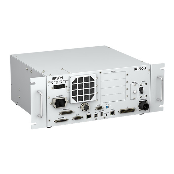
Epson RC700 Manual (316 pages)
ROBOT CONTROLLER
Brand: Epson
|
Category: Controller
|
Size: 40 MB
Table of Contents
Advertisement
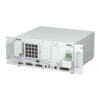
Epson RC700 Manual (340 pages)
Robot Controller Option Fieldbus I/O
Brand: Epson
|
Category: Controller
|
Size: 12 MB
Table of Contents

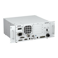
Epson RC700 Original Instructions Manual (228 pages)
ROBOT CONTROLLER
Brand: Epson
|
Category: Controller
|
Size: 6 MB
Table of Contents
Advertisement
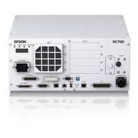
Epson RC700 Manual (274 pages)
Robot Controller Fieldbus I/O
Brand: Epson
|
Category: Controller
|
Size: 6 MB
Table of Contents

Epson RC700 Manual (120 pages)
Robot Controller Option Teach Pendant
Brand: Epson
|
Category: Controller
|
Size: 1 MB
Table of Contents
Epson RC700 Maintenance Manual (90 pages)
ROBOT CONTROLLER
Brand: Epson
|
Category: Controller
|
Size: 5 MB
Table of Contents

Epson RC700 Manual (66 pages)
PG Motion System
Brand: Epson
|
Category: Controller
|
Size: 1 MB