Sign In
Upload
Manuals
Brands
Bonfiglioli Manuals
Inverter
Active Cube
Bonfiglioli Active Cube Manuals
Manuals and User Guides for Bonfiglioli Active Cube. We have
8
Bonfiglioli Active Cube manuals available for free PDF download: Applications Manual, Operation Manual, User Manual, Instruction Manual, Manual, Installation Manual
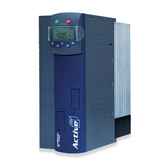
BONFIGLIOLI Active Cube Applications Manual (166 pages)
Brand:
BONFIGLIOLI
| Category:
DC Drives
| Size: 4.4 MB
Table of Contents
Table of Contents
4
1 General Safety Instructions and Information on Use
9
General Information
9
Purpose of the Frequency Inverters
9
Transport and Storage
9
Handling and Installation
10
Electrical Installation
10
Information on Use
11
Using External Products
11
Maintenance and Service
11
Disposal
11
2 Description of System VPLC
12
Chronological Processing
13
Creating a Program with Function Blocks
14
Starting VPLC
14
Saving a File
14
Function Block (Instruction)
14
Wire
14
Digital Input Block
15
Analog Input Block
15
Digital Output Block
15
Analog Output Block
16
Example
16
Syntax Check
16
Translation and Download (to Frequency Inverter)
16
Starting the PLC
16
Stopping the PLC
16
User Environment
17
Tool Bar and Menu Commands
17
Other Menu Commands
18
Editor
19
Library
19
Properties
19
Settings: Inputs, Outputs and Function Block
20
Starting the PLC Functions
23
Principle for Digital Functions (Input Settings [Boolean])
23
Principle for Analog Functions
25
Input Buffer and Output Buffer for Digital Signals
27
Input Buffer and Output Buffer for Analog Signals
27
Fixed Analog Values
29
3 Overview of Instructions
30
Inputs and Outputs
37
Inputs of Digital Functions
37
Inputs and Outputs of Analog Functions
38
Combination of Inputs and Outputs of Instructions
40
Inputs
40
Combining Input Buffer with Inputs
43
Digital
43
Analog
43
Combining Instructions with One Another
44
Activating Device Functions Via the Output Buffer
44
Controlling a Digital Output Via the Output Buffer
46
Controlling an Analog Output Via the Output Buffer
47
4 Description of Digital Functions
48
Superior/Master
49
P1 and P2 for Chronological Behavior and Jump Target
49
Chronological Behavior
50
Jump Target
50
Overview Table
50
Boolean Operations
51
1] and Operation
52
2] or Operation
52
3] XOR 1 Operation
53
4] XOR 1||3 Operation
53
Flip-Flop Types
54
10] RS-Flip-Flop, Superior
54
110] RS-Flip-Flop, Master
55
20] Toggle-Flip-Flop, Superior
56
120] Toggle-Flip-Flop, Master
57
30] D-Flip-Flop, Superior
58
130] D-Flip-Flop, Master
59
Delays
60
40,41,42] Delay (Retriggerable), Superior
63
140,141,142] Delay (Retriggerable), Master
64
50,51,52] Delay (Non-Retriggerable), Superior
65
150,151,152] Delay (Non-Retriggerable), Master
66
Timer Functions
67
60,61,62] Monoflop (Retriggerable), Superior
67
160,161,162] Monoflop (Retriggerable), Master
68
70,71,72] Monoflop (Non-Retriggerable), Superior
69
170,171,172] Monoflop (Non-Retriggerable), Master
70
80,81,82] Clock Generator Superior
71
180,181,182] Clock Generator, Master
72
Digital Multiplexer
73
Digital Multiplexer (Data Set Number)
73
Switch
73
Switch Data Set
73
Error Functions
74
Triggering of an Error
74
Acknowledging an Error
75
Debouncer
76
No Operation
76
99] NOP (no Operation)
76
Jump Functions
77
100] Jump Function
77
101] Jump Function for Loops
78
5 Description of Analog Functions
79
Behavior
79
Comparators
80
301,302] Comparator (Comparison of Two Variables)
80
303,304] Comparator (Comparison of Constant to Variable)
81
308] Comparator for Motion Blocks
83
Position Comparator (Long)
84
Analog Hysteresis
85
311,312] Window Comparator (Comparison of Two Variables)
86
313,314] Window Comparator (Comparison of Constant to Variable)
87
320] Min/Max
89
Min / Max for Position Values (Long)
89
322] Min/Max in Time Window
90
323] Min/Max for Positions (Long) in Time Window
90
Mathematical Functions
92
Addition and Subtraction
93
Add. O1=-O2=I1+I2-I3+P1-P2
93
331] Addition Position with Offset
93
Multiplication
94
333] Multiplication, Long Result
94
334] Mult. by Fraction
95
335] Mult. Long * Percent
95
Division
96
337] Division by Constant
97
338] Division P1 by I1, Reciprocal
97
Multiplication and Division
98
Average Function
98
Absolute Value of Two Orthogonal Components (2 D Vector)
99
Absolute Value of Three Orthogonal Components (3 D Vector)
99
350] Integrator
100
351] Differentiator (D-Element)
101
360] Absolute Value Function
101
361] X², Sqr (I1)
102
362] X³, (Cube (I1)
102
363] √X, Square Root of I1
102
364] Modulo
103
Controller
104
370] P Controller
104
PI Controller (Tn in Milliseconds)
105
PI Controller (Tn in Seconds)
105
373] PD(T1) Controller
106
374] PID(T1) Controller (Tn in Milliseconds)
106
375] PID(T1) Controller (Tn in Seconds)
107
Filters
109
380] PT1 Element
109
381] Time Average
109
382] Ramp Limitation
110
383] Spike Filter (Average of Three)
111
Analog Switch
112
Analog Multiplexer (Data Set Number)
112
Analog Changeover Switch
112
MUX for Position Values (Data Set Number), Multiplexer
113
Changeover Switch for Position Values (Long)
113
Parameter Access
114
Writing Parameters
114
Write Frequency Parameter
114
402] Write Current Parameter
115
403] Write Voltage Parameter (Eff.)
115
404] Write Voltage Parameter (Peak)
116
405] Write Percentage Parameter
116
406] Write Position Parameter
116
407] Write Long Parameter
117
408] Write Word Parameter
117
Reading Parameters
118
421] Read Frequency Parameter
118
422] Read Current Parameter
118
423] Read Voltage Parameter (Eff.)
119
424] Read Voltage Parameter (Peak)
119
425] Read Percent Parameter
119
426] Read Position Parameter
119
427] Read Long Parameter
120
428] Read Word Parameter
120
Limiters
120
440] Limiter (Const.)
120
441] Limiter (Variable)
121
Counters
121
450] Up/Down Counter with Analog Output
121
451] Stopwatch with Analog Output
122
Positioning Functions
123
501] Start Motion Block as Single Motion
124
502] Start Motion Block in Automatic Mode
125
503] Stop Motion Block
125
504] Continue Motion Block
126
505] Resume Motion Block
126
506] Start Homing
127
507] Check State
127
Bit Functions for Analog Input Values
128
200] Bit NOT Operation
128
201] Bit AND/NAND Operation
129
202] Bit OR/NOR Operation
130
203] Bit XOR/XNOR Operation
131
210] Bit Shift Right
131
211] Bit Arithmetical Shift Right
132
212] Bit Shift Left
132
213] Bit Roll Right
133
220] Output One Bit
133
221] Unite Four Bits to Form a Word
134
222] Add Two Bits to a Word
135
6 Examples of Combinations in the Function Table
136
Write Index and Read Index
136
Write Index and Read Index for FT-Instructions
136
Write Index and Read Index for the Digital Input Buffer
137
Write Index and Read Index for the Analog Input Buffer and FT Fixed Values
138
Run/Stop
139
Example Run/Stop
140
Example 1: Combining Two Digital Outputs
140
Example 2: Combining Several FT-Instructions
141
Example 3: Parameterization of Logic Diagram
144
7 Actual Values, Output Signals and Messages
145
Actual Values of Digital Functions
145
Actual Values of Analog Functions
147
Signals for Digital Outputs of Device
148
Signals for Analog Outputs of Device
148
Signal Sources for Device Function
149
Error Messages of Instruction "95 - Triggering an Error
149
8 Operation as State Machine
150
Example of a Controller
150
9 List of Parameters
157
Actual Values
157
Parameters of Function Table
158
10 Annex
160
Mask: Diagram for Digital Instructions of Function Table
160
Mask: Functions Settings
161
Index
162
Advertisement
Bonfiglioli Active Cube User Manual (130 pages)
Frequency Inverter 230 V/400 V
Brand:
Bonfiglioli
| Category:
Inverter
| Size: 2.71 MB
Table of Contents
Table of Contents
3
1 General Information about the Documentation
7
Instructions
7
Pictograms and Signal Words Used
8
Copyright
8
2 General Safety Instructions and Information on Use
9
General Information
9
Designated Use
9
Transport and Storage
10
Handling and Installation
10
Electrical Installation
10
Information on Use
11
Operation with Products from Other Manufacturers
11
Maintenance and Service
11
Disposal
11
3 Introduction
12
Restrictions for Operation of Standard Functions
13
Range of Applications of Encoders
14
Asynchronous Motor
14
Synchronous Motor
14
4 Technical Data
15
5 Installation
17
General
17
Mechanical Installation
17
Electrical Installation
19
Block Diagram
19
Control Terminals
21
Cable Assembly Sincos
23
Cable Assembly Endat 2.1
24
Cable Assembly Hiperface
25
Power Supply
26
Internal Power Supply
26
Looping Via Terminals X410A
27
Direct Connection of External Power Supply to the Encoder
28
6 Commissioning the Encoder
29
General Information
29
Information on Use
30
Sincos Encoders
31
Hiperface Encoders
32
Endat 2.1 Encoders
33
SSI Encoders
34
Commissioning of Linear Encoders
36
Checking the Settings
41
Initialize Counting Direction
43
Initializing Home Position
43
7 System Bus Interface
44
Bus Termination
44
Cables
45
Control Terminal X410B
45
Baud Rate Setting/Line Lengths
46
Setting the Node Address
46
Functional Overview
47
Network Management
47
SDO Channels (Parameter Data)
48
PDO Channels (Process Data)
48
Master Functionality
49
Control Boot-Up Sequence, Network Management
49
SYNC Telegram, Generation
51
Emergency Message, Reaction
52
Client SDO (System Bus Master)
53
Slave Functionality
54
Implement Boot-Up Sequence, Network Management
54
Boot-Up Message
54
Position Control
54
Process SYNC Telegram
55
Selecting the Synchronization Source
55
Settings for Electronic Gear in Configuration X40
57
Scope Sources
57
Emergency-Message, Fault Shutdown
58
Server-SDO1/SDO2
59
Communication Channels, SDO1/SDO2
61
SDO Telegram (SDO1/SDO2)
61
Communication Via Field Bus Actuation (SDO1)
63
Profibus-DP
63
RS232/RS485 with VECTRON Bus Protocol
63
Process Data Channels, PDO
65
Identifier Assignment Process Data Channel
65
Operation Modes Process Data Channel
66
Timeout Monitoring Process Data Channel
67
Communication Relationships of the Process Data Channels
68
Virtual Links
69
Input Parameters of the Txpdos for Data to be Transmitted
72
Source Numbers of the Rxpdos for Received Data
74
Examples of Virtual Links
75
Control Parameters
76
Handling of the Parameters of the System Bus
77
Ancillaries
79
Definition of the Communication Relationships
80
Production of the Virtual Links
81
Capacity Planning of the System Bus
82
8 Control Inputs and Outputs
84
Analog Input EM S1INA
84
General
84
Characteristic
84
Operation Modes
85
Examples
85
Scaling
88
Tolerance Band and Hysteresis
89
Error and Warning Behavior
90
Adjustment
91
Filter Time Constant
91
Digital Outputs EM-S1OUTD and EM-S2OUTD
92
General
92
Operation Modes
92
Repetition Frequency Output Via EM-S1OUTD and EM-S2OUTD
92
Digital Inputs EM-Sxind
93
Fixed Reference Value and Fixed Value Change-Over
93
Encoder Input EM-ABS-01
94
Division Marks
94
Tracks/Protocol
95
Power Supply
98
Supply Voltage
101
Speed Filter
102
Offset
102
Bits/Turn
104
Bits Multiturn
105
SSI: Error/Additional Bits
106
Example 1
107
Example 2
107
Example 3
107
Example 4
107
SSI: Sampling Interval
108
Gear Factor Speed Sensor 2
108
Example
109
Instructions on Speed-Controlled Configurations ("Not X40")
109
Instructions on Positioning (Configuration X40)
110
Example
111
Homing
112
Warning Dig. Encoder
112
Act. Speed Source
113
Actual Position Source
113
Reference Frequency and Percentage Value Channel
114
Actual Value Display
114
Absolute Value Encoder - Raw Data
115
Actual Position
115
Status of Digital Signals
116
Motor Temperature
117
9 List of Parameters
118
Actual Value Menu (VAL)
118
Parameter Menu (PARA)
118
10 Annex
121
Recommended Encoder Settings
121
Sincos Encoders
121
Hiperface Encoders
122
Endat2.1 Encoders
122
SSI Encoders, Rotary
123
SSI Encoders, Linear Encoders
123
Compatibility List
124
Module Firmware 1.0.1.0
124
Module-Firmware 2.0.1.0
124
Error Messages
125
Index
128
BONFIGLIOLI Active Cube Operation Manual (134 pages)
Brand:
BONFIGLIOLI
| Category:
Inverter
| Size: 4.76 MB
Table of Contents
Table of Contents
3
1 General Information about the Documentation
7
This Document
7
Warranty and Liability
8
Obligation
8
Copyright
8
Storage
8
2 General Safety Instructions and Information on Use
9
Terminology
9
Designated Use
10
Misuse
10
Explosion Protection
10
Residual Risks
11
Safety and Warning Signs on the Frequency Inverter
11
Warning Information and Symbols Used in the User Manual
12
Hazard Classes
12
Hazard Symbols
12
Prohibition Signs
12
Personal Safety Equipment
12
Recycling
13
Grounding Symbol
13
ESD Symbol
13
Information Signs
13
Font Style in Documentation
13
Directives and Guidelines to be Adhered to by the Operator
13
Operator's General Plant Documentation
13
Operator's/Operating Staff's Responsibilities
14
Selection and Qualification of Staff
14
General Work Safety
14
Organizational Measures
14
General
14
Use in Combination with Third-Party Products
14
Transport and Storage
15
Handling and Installation
15
Electrical Connections
15
Safe Operation
15
Maintenance and Service/Troubleshooting
16
Final Decommissioning
16
3 Introduction
17
Supported Configurations
19
Initialization Time
20
4 First Commissioning
20
5 Assembly/Disassembly of Communication Module
21
Assembly
21
Disassembly
22
6 Modbus/Tcp Interface
23
Communication Modules
24
Installation Instructions
25
Setup
25
TCP/IP Configuration
25
TCP/IP Address & Subnet Settings
26
Modbus/Tcp Timeout Settings
26
Operating Behavior in the Case of a Communication Error
27
7 Protocol
28
Telegram Structure
28
Supported Function Codes
29
Function Code 3, Reading 16-Bit or 32-Bit Parameters
30
Function Code 6, Write 16-Bit Parameter
31
Function Code 16, Write 16-Bit Parameter
33
Function Code 16, Write 32-Bit Parameter
34
Function Code 100 (=0X64), Read 32-Bit Parameter
35
Function Code 101 (=0X65), Write 32-Bit Parameter
36
Function Code 8, Diagnosis
38
Exception Condition Responses
40
Exception Condition Codes
41
Modbus/Tcp Mode of Transmission
42
Resetting Errors
42
8 Parameter Access
43
Handling of Datasets / Cyclic Writing of Parameters
43
Handling of Index Parameters / Cyclic Writing
44
Example: Writing of Index Parameters
45
Example: Reading of Index Parameters
45
9 Example Messages Modbus/Tcp
46
16-Bit Access
46
Function Code 3, Read 16-Bit Parameter
46
Function Code 6, Write 16-Bit Parameter
47
Function Code 16, Write 16-Bit Parameter
48
32-Bit Access
49
Function Code 3, Read 32-Bit Parameter
49
Function Code 16, Write 32-Bit Parameter
50
Function Code 100 (=0X64), Read 32-Bit Parameter
51
Function Code 101 (=0X65), Write 32-Bit Parameter
52
Function Code 8, Diagnosis
53
10 Motion Control Interface (MCI) / Motion Control Override (MCO)
54
Motion Control Override
55
Functions of Motion Control Interface (MCI)
60
Reference System
60
Modes of Operation
60
Current Position and Contouring Errors
61
Target Window
61
Position Controller
62
Homing
63
Move Away from Hardware Limit Switches
64
11 Control of Frequency Inverter
65
Control Via Contacts/Remote Contacts
66
Device State Machine
68
Control Via State Machine
69
Statemachine Diagram
71
Configurations Without Motion Control
74
Behavior in the Case of a Quick Stop
74
Behavior in the Case of Transition 5 (Disable Operation)
75
Reference Value/Actual Value
76
Example Sequence
77
Motion Control Configurations
78
Velocity Mode [Rpm]
79
Profile Velocity Mode [U/S] (Pv)
84
Profile Position Mode
88
Homing Mode
96
Table Travel Record
99
Move Away from Limit Switch Mode
107
Electronic Gear: Slave
111
12 Actual Values
122
13 Parameter List
123
Parameters (Menu "Para")
124
14 Appendix
126
Overview of Status Words
127
Warning Messages
128
Application Warning Messages
129
Error Messages
130
Conversions
131
Index
132
Advertisement
BONFIGLIOLI Active Cube Instruction Manual (60 pages)
Brand:
BONFIGLIOLI
| Category:
Inverter
| Size: 1.46 MB
Table of Contents
Installation Instructions
3
Table of Contents
4
1 General Safety and Application Information
6
General Information
6
Proper Use
6
Transport and Storage
7
Handling and Positioning
7
Electrical Connection
7
Operation Information
7
Maintenance and Service
7
2 Introduction
8
3 Installation of the EM-ENC-03 Expansion Module
9
General
9
Mechanical Installation
9
Electrical Installation
11
Circuit Diagram
11
Sockets
12
4 System Bus Interface
13
Bus Termination
13
Cables
14
Socket X410B
14
Baud Rate Setting/Line Length
15
Setting Node Address
15
Functional Overview
16
Network Management
16
SDO Channels (Parameter Data)
17
PDO Channels (Process Data)
17
Master Functionality
18
Control Boot-Up Sequence, Network Management
18
SYNC Telegram, Generation
20
Emergency Message, Reaction
21
Client SDO (System Bus Master)
22
Slave Functionality
23
Implement Boot-Up Sequence, Network Management
23
Boot-Up Message
23
Status Control
23
Process SYNC Telegram
24
Emergency Message, Fault Switch-Off
25
Server SDO1/SDO2
26
Communication Channels, SDO1/SDO2
28
SDO Telegrams (SDO1/SDO2)
28
Communication Via Field Bus Connection (SDO1)
30
4.10.2.1 Profibus-DP
30
4.10.2.2 RS232/RS485 with VECTRON Bus Protocol
30
Process Data Channels, PDO
32
Identifier Assignment Process Data Channel
32
Operation Modes Process Data Channel
33
Timeout Monitoring Process Data Channel
34
Communication Relationships of the Process Data Channel
35
Virtual Links
36
Input Parameters of the Txpdo's for Data to be Transmitted
39
4.11.5.2 Source Numbers of the Rxpdo's for Received Data
41
4.11.5.3 Examples of Virtual Links
42
Control Parameters
43
Handling of the Parameters of the System Bus
44
Utilities
46
Definition of the Communication Relationships
47
Creating Virtual Links
48
Capacity Planning of the System Bus
49
5 Control Inputs and Outputs
51
Speed Sensor Input EM-ENC
51
Termination Resistor
51
Division Marks
52
Level
52
Actual Speed Source
53
Actual Value Comparison
53
Frequency and Percentage Reference Channel
53
Actual Value Display
53
6 Parameter List
54
Actual Value Menu (VAL)
54
Parameter Menu (PARA)
54
7 Annex
56
Error Messages
56
BONFIGLIOLI Active Cube Applications Manual (44 pages)
Spindle Drive Frequency inverter 230 V / 400 V
Brand:
BONFIGLIOLI
| Category:
Inverter
| Size: 2.25 MB
Table of Contents
Table of Contents
3
1 General Information about the Documentation
5
This Document
5
Installation Instructions
5
Warranty and Liability
6
Obligation
6
Copyright
6
Storage
7
2 General Safety Instructions and Information on Use
8
Terminology
8
Designated Use
9
Misuse
9
Explosion Protection
9
Residual Risks
10
Safety and Warning Signs on Frequency Inverter
10
Warning Information and Symbols Used in the Operating Instructions
11
Hazard Classes
11
Hazard Symbols
11
Prohibition Signs
11
Personal Safety Equipment
11
Recycling
12
Grounding Symbol
12
ESD Symbol
12
Information Signs
12
Font Style in Documentation
12
Directives and Guidelines to be Adhered to by the Operator
13
Operator's General Plant Documentation
13
Operator's/Operating Staff's Responsibilities
13
Selection and Qualification of Staff
13
General Work Safety
13
Organizational Measures
14
General
14
Use in Combination with Third-Party Products
14
Transport and Storage
14
Handling and Installation
15
Electrical Connections
15
The Five Safety Rules
15
Safe Operation
16
Maintenance and Service/Troubleshooting
17
Final Decommissioning
17
3 Introductory Information about Spindle Applications
18
Configurations for Spindle Applications
18
Software Identification
19
Operating Characteristics
20
Control Inputs and Outputs
21
Control Terminals
21
Start-Up Procedure
22
Check Speed Sensors for Sign Error
23
For Configuration 806 (PMSM): Self-Configuration of Resolver Offset
24
Safety Measures before Self-Configuration of Resolver Offset
25
5 Operation
26
Determination of the Flux Direction at Startup
27
Operation with Field Weakening
28
4 Start
29
Adjustment of Resolver Offset
30
Speed Sensor Monitoring
31
Brake Chopper Monitoring
32
Detection of Spindle with Inverse Behavior
33
Asynchronous Machine (ASM) – Configuration 804
34
Identification of Reference Point Position
35
Status Message "Target Position Reached
36
Control of Acceleration Ramps Via Digital Input
37
6 Overview of Sources
38
7 Actual Values
38
8 Parameter
39
Index
40
BONFIGLIOLI Active Cube Manual (44 pages)
Profibus-DP, Communication module CM-PDP, Frequency inverter 230V/400V
Brand:
BONFIGLIOLI
| Category:
DC Drives
| Size: 0.85 MB
Table of Contents
Table of Contents
4
1 General Safety and Application Information
6
General Information
6
Proper Use
6
Transport and Storage
7
Handling and Positioning
7
Electrical Connection
7
Operation Information
7
Maintenance and Service
7
2 Introduction
8
3 Assembly of the Profibus-DP Communication Module CM-PDP
9
4 Socket Occupancy/Bus Termination/Line
10
5 Baud Rate Setting/Line Length
11
6 Setting Station Address
11
7 Setting PPO Type
11
Configuration Process on the DP Master
12
8 Commands SYNC / FREEZE
13
9 Available Objects / Scanning Times
13
10 Handling of the Objects
15
Communication Channel
15
Order Identification
16
Reply Identification
16
Fault Messages
16
Parameters, Data Set Selection and Cyclic Writing
17
Sequence of Communication
18
Examples of Communication
19
Process Data Channel PZD1/PZD2
21
PZD1, Control Word / State Word
21
Control Via Contacts
22
Control Via State Machine
23
10.2.3.1 Behavior in Quick Stop
26
Behavior in Transition 5
26
Control Via Remote Contacts
27
PZD2, Reference Value / Actual Value
29
Variable Actual Value Reporting Via PZD2 in PPO1 / PPO3
30
Actual Value Report PZD2 to PZD6 in PPO2 / PPO4
32
PPO-Out Data as Global Sources
32
Actual Value Display of Profibus Data
37
11 Parameter List
39
12 Annex
40
GSD File – VEC_0696.GSD
41
BONFIGLIOLI Active Cube Applications Manual (40 pages)
Frequency inverter
Brand:
BONFIGLIOLI
| Category:
Inverter
| Size: 1.21 MB
Table of Contents
Table of Contents
4
1 General Safety Instructions and Information on Use
5
General Information
5
Purpose of the Frequency Inverters
6
Transport and Storage
6
Handling and Installation
6
Electrical Connection
7
Information on Use
7
Maintenance and Service
7
2 Control Inputs and Outputs
8
Control Terminals
8
3 Commissioning of the Frequency Inverter
12
Switching on Mains Voltage
12
Setup Using the Control Unit
12
4 Electronic Gear
14
Scope of Functions
14
Operation Modes of Electronic Gear
15
Gear Factor
15
Setting a Fixed Gear Factor
15
Setting a Variable Gear Factor
16
Offset Switches
17
Reference Value and Actual Value Input
18
Position Control
19
Index Control
21
Scope Sources
23
Actual Values
23
Adjustment Options
24
Frequency Inverter as Master
24
Frequency Inverter as Slave
25
Examples of Wiring
27
5 Electronic Gear Via System Bus
30
Speed Sensor Simulation
30
Adjustment Options
31
Frequency Inverter as Master
31
Slave Settings
32
Position Control Via System Bus
33
6 Parameter List
34
Actual Value Menu (VAL)
34
Parameter Menu (PARA)
35
BONFIGLIOLI Active Cube Installation Manual (21 pages)
230 V / 400 V
Brand:
BONFIGLIOLI
| Category:
DC Drives
| Size: 0.6 MB
Table of Contents
Table of Contents
3
1 Scope of Supply for Devices in "Cold Plate" Variant
4
ACT/ACU 201 (up to 3.0 Kw) and ACT/ACU 401 (up to 4.0 Kw)
4
ACT/ACU 201 (4.0 to 9.2 Kw) and ACT/ACU 401 (5.5 to 15.0 Kw)
5
ACT/ACU 401 (18.5 to 30.0 Kw)
6
2 Technical Data
7
ACT/ACU 201 (0.55 to 3.0 Kw, 230 V)
7
ACT/ACU 201 (4.0 to 9.2 Kw, 230 V)
7
ACT/ACU 401 (0.55 to 4.0 Kw, 400 V)
8
ACT/ACU 401 (5.5 to 15.0 Kw, 400 V)
8
ACT/ACU 401 (18.5 to 30.0 Kw, 400 V)
8
3 Range of Application
9
4 Thermal Properties of the Heat Sink
10
Thermal Resistance
10
ACT/ACU 201 (0.55 to 3.0 Kw, 230 V)
11
ACT/ACU 201 (4.0 to 9.2 Kw, 230 V)
11
ACT/ACU 401 (0.55 to 4.0 Kw, 400 V)
12
ACT/ACU 401 (5.5 to 15.0 Kw, 400 V)
12
ACT/ACU 401 (18.5 to 30.0 Kw, 400 V)
13
Fan and Liquid Cooling
14
5 Application Notes
15
6 Mechanical Installation
16
ACT/ACU 201 (up to 3.0 Kw) and ACT/ACU 401 (up to 4.0 KW)
16
ACT/ACU 201 (4.0 to 9.2 Kw) and ACT/ACU 401 (5.5 to 15.0 Kw)
17
ACT/ACU 401 (18.5 to 30.0 Kw)
18
Installation
19
7 Temperature Monitoring
19
Advertisement
Related Products
BONFIGLIOLI ACTIVE CUBE Series
BONFIGLIOLI actice
BONFIGLIOLI ACTIVE Cube ACU 201-01
BONFIGLIOLI ACTIVE Cube ACU 201-07
BONFIGLIOLI ACTIVE Cube ACU 201-13
BONFIGLIOLI ACTIVE Cube ACU 201-19
BONFIGLIOLI ACTIVE Cube ACU 401-21
BONFIGLIOLI ACTIVE Cube ACU 401-25
BONFIGLIOLI ACTIVE Cube ACU 401-29
BONFIGLIOLI ACTIVE Cube ACU 401-45
Bonfiglioli Categories
DC Drives
Engine
Inverter
Industrial Equipment
Controller
More Bonfiglioli Manuals
Login
Sign In
OR
Sign in with Facebook
Sign in with Google
Upload manual
Upload from disk
Upload from URL