Table of Contents
Advertisement
Advertisement
Table of Contents

Related Manuals for Delta ASD-A2 Series


Summary of Contents for Delta ASD-A2 Series
- Page 1 V5.1 DELTA_IA-ASDA_A2_UM_EN_20170209...
- Page 2 Preface Thank you for purchasing ASDA-A2. This user manual provides the related information of ASDA- A2R series servo drive and ECMA series servo motors. This manual includes: Installation and inspection of servo drive and servo motor The configuration of servo drive ...
- Page 3 Preface ASDA-A2 Safety Precautions ASDA-A2 series is the high resolution and open type servo drive. It should be installed in a shielded control box during operation. This servo drive uses precise feedback control and the digital signal processor with high-speed calculation function to control the current output which generated by IGBT so as to operate three-phase permanent magnet synchronous motors (PMSM) and to achieve precise positioning.
- Page 4 ASDA-A2 Preface Operation Before the operation, please change the parameter setting value according to the needs. If it is not adjusted to the correct setting value, it is possible to lead to malfunction of the machine or the operation might out of control. Before the machine starts to operate, please be ensured the emergency stop can be ...
- Page 5 Preface ASDA-A2 Main Circuit Wiring Do not put the power cable and the encoder cable in the same channel and bond them together. Please separate the power cable and the encoder cable for at least 30 centimeters (= 11.8 inches) when wiring. Please use stranded wires and multi-core shielded-pair wires for the encoder cables ...
-
Page 6: Table Of Contents
Table of Contents Chapter 1 Inspection and Model Explanation ..............1-1 Inspection ........................ 1-1 Product Model ......................1-3 1.2.1 Nameplate Information ..................1-3 1.2.2 Model Explanation ..................... 1-4 Servo Drive and Corresponding Servo Motor ............1-6 1.3.1 220 V Series ...................... 1-6 1.3.2 400 V Series ...................... - Page 7 ASDA-A2 Table of Contents 3.1.2 Connectors and Terminals of Servo Drive ............3-2 3.1.3 Wiring Method ....................3-4 3.1.4 Specification of Motor Power Cable ..............3-6 3.1.5 Specification of Encoder Cable Connector ............3-8 3.1.6 Selection of Wiring Rod ..................3-12 Connections –...
- Page 8 Table of Contents ASDA-A2 CN4 Serial Connector (USB) ................... 3-59 CN5 Connector (Full-closed loop) ................3-60 CN6 Connector (CANopen) ..................3-61 3.10 Extension Digital Input Connector of CN7 ............... 3-63 3.11 CN8 Connector of Battery Box ................3-64 3.12 Standard Connection Example – 220V series ............3-65 3.12.1 Position (PT) Control Mode ................
- Page 9 ASDA-A2 Table of Contents 4.3.5 Monitor Display ....................4-6 General Function ..................... 4-9 4.4.1 Operation of Fault Record Display ..............4-9 4.4.2 JOG Mode ......................4-10 4.4.3 Force DO Output ....................4-11 4.4.4 Digital Input Diagnosis Operation ..............4-12 4.4.5 Digital Output Diagnosis Operation ..............
- Page 10 Table of Contents ASDA-A2 6.2.1 Position Command in PT Mode ................. 6-3 6.2.2 Position Command in PR Mode ................ 6-7 6.2.3 Control Structure of Position Mode..............6-8 6.2.4 S-curve Filter (Position) ..................6-9 6.2.5 Electronic Gear Ratio ..................6-12 6.2.6 Low-pass Filter ....................
- Page 11 ASDA-A2 Table of Contents 6.5.2 Speed / Torque Dual Mode ................6-50 6.5.3 Torque / Position Dual Mode ................6-51 Others ........................6-52 6.6.1 The Use of Speed Limit ..................6-52 6.6.2 The Use of Torque Limit ..................6-52 6.6.3 Analog Monitor ....................
- Page 12 Table of Contents ASDA-A2 Chapter 8 Parameters ......................8-1 Parameter Definition ....................8-1 List of Parameters ....................8-2 Parameter Description ................... 8-13 P0-xx Monitor Parameters ..................8-13 P1-xx Basic Parameters ..................... 8-40 P2-xx Extension Parameters ..................8-91 P3-xx Communication Parameters ................8-136 P4-xx Diagnosis Parameters ..................
- Page 13 ASDA-A2 Table of Contents Chapter 11 Specifications ....................11-1 11.1 Specifications of Servo Drives ................. 11-1 11.1.1 ASDA-A2 220V Series ..................11-1 11.1.2 ASDA-A2 400V Series ..................11-4 11.2 Specifications of Servo Motors (ECMA Series) ............11-7 11.2.1 ECMA 220V Series..................11-7 11.2.2 ECMA 400V Series..................
- Page 14 Table of Contents ASDA-A2 12.2.2 How to Install a Battery .................. 12-12 12.2.3 How to Replace a Battery ................12-13 12.3 System Initialization Procedure and Operation ............. 12-15 12.3.1 System Initialization Procedure ..............12-15 12.3.2 Pulse Counting ....................12-16 12.3.3 PUU Counting....................
- Page 15 Due to constantly growing product range, technical improvement and alteration or changed texts, figures and diagrams, we reserve the right of this manual contained information change without prior notice. Coping or reproducing any part of this manual, without written consent of Delta Electronics Inc. is prohibited. Technical Support and Service...
- Page 16 Chapter 1 Inspection and Model Explanation 1.1 Inspection In order to prevent the negligence during purchasing and delivery, please inspect the following items carefully. Please check if the product is what you have purchased: check the part number of the motor and the servo drive on the nameplate.
-
Page 17: Chapter 1 Inspection And Model Explanation
ASDA-A2 Chapter 1 Inspection and Model Explanation (10) Servo drive power input: 220V: Control circuit power Main circuit power L1c, L2C, fast connector 100 W ~ 3 kW R, S, T fast connector L1c, L2C, terminal block 405 kW ~ 15 kW R, S, T terminal block 400V: Control circuit power... -
Page 18: Product Model
19XK IND. CONT. EQ. 200~230V 1PH 50/60Hz 3.22A Rated Current Output OUTPUT : 110V 0-250Hz 2.6A Barcode A20421LT14130102 Firmware Version 01.34 DELTA ELECTRONICS, INC. MADE IN TAIWAN Serial Number ECMA Series Servo Motor Nameplate Information Serial Number ... -
Page 19: Model Explanation
ASDA-A2 Chapter 1 Inspection and Model Explanation 1.2.2 Model Explanation ASDA-A2 Series Servo Drive A S D - A 2 - 0 7 4 3 - U Model Type Input Voltage and Phase 21: 220V 1 phase 23: 220V 3 phase 43: 400V 3 phase Rate Output Power 01: 100W... - Page 20 Chapter 1 Inspection and Model Explanation ASDA-A2 ECMA Series Servo Motor E C M A - C 1 0 6 0 2 E S Standard Shaft Diameter: S Specific Shaft Diameter: 3=42mm, 7=14mm Type of Shaft with With Diameter and Brake, Brake, Brake,...
-
Page 21: Servo Drive And Corresponding Servo Motor
ASDA-A2 Chapter 1 Inspection and Model Explanation 1.3 Servo Drive and Corresponding Servo Motor 1.3.1 220V Series Motor Servo Drive Max. Continuous Max. Rated Motor Output Instantaneous Output Instantaneous Power Model Number Current Model Number series current Current output current (Arms) (Arms) ECMA-C1040F□S... - Page 22 Chapter 1 Inspection and Model Explanation ASDA-A2 Motor Servo Drive Max. Max. Continuou Instanta Rated Motor Output Instantaneous s Output neous Power Model Number Current Model Number series current Current output (Arms) (Arms) current ECMA-C△0604□H 2.60 7.80 ASD-A2-0421-□ 2.60 7.80 ECMA-C△0807□H 5.10 15.30...
-
Page 23: Series
ASDA-A2 Chapter 1 Inspection and Model Explanation 1.3.2 400V Series Motor Servo Drive Max. Continuous Max. Rated Motor Output Instantaneous Output Instantaneous Power Model Number Current Model Number series current Current output current (Arms) (Arms) ECMA-J 0604 S 1.62 4.85 ASD-A2-0743-□... -
Page 24: Each Part Of The Servo Drive
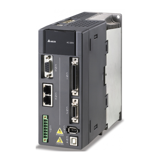
Chapter 1 Inspection and Model Explanation ASDA-A2 1.4 Each Part of the Servo Drive 1.4.1 220V Series 220V Series - Front View Revision February, 2017... - Page 25 ASDA-A2 Chapter 1 Inspection and Model Explanation 220V Series - Top View 1-10 Revision February, 2017...
- Page 26 Chapter 1 Inspection and Model Explanation ASDA-A2 220V Series - Bottom View 1-11 Revision February, 2017...
-
Page 27: Series
ASDA-A2 Chapter 1 Inspection and Model Explanation 1.4.2 400V Series 400V Series - Front View 1-12 Revision February, 2017... - Page 28 Chapter 1 Inspection and Model Explanation ASDA-A2 400V Series - Top View 1-13 Revision February, 2017...
- Page 29 ASDA-A2 Chapter 1 Inspection and Model Explanation 400V Series - Bottom View 1-14 Revision February, 2017...
-
Page 30: Chapter 2 Installation
Chapter 2 Installation 2.1 Notes Please pay special attention to the followings: If the connection between the servo drive and the servo motor is over 20 meters, please thicken the connecting wire, UVW as well as the encoder cable. Please refer to section 3.1.6 for further information. -
Page 31: Installation Direction And Space
ASDA-A2 Chapter 2 Installation 2.4 Installation Direction and Space Notes: Incorrect installation may result in a drive malfunction or premature failure of the drive and motor. The ASDA-A2 servo drive should be mounted perpendicular to the wall or in the control panel. In order to ensure the drive is well ventilated, ensure that the all ventilation holes are not obstructed and sufficient free space is given to the servo drive. - Page 32 Chapter 2 Installation ASDA-A2 Scheme of Installation: In order to have smaller wind resistance of the fan and increase the ventilation, please follow the suggested clearance value when installing one or more than one servo drives. (Refer to the following diagrams) The above diagrams are not in equal proportion.
- Page 33 ASDA-A2 Chapter 2 Installation The above diagrams are not in equal proportion. Please refer to the NOTE annotation. Revision February, 2017...
-
Page 34: Specification Of Circuit Breaker And Fuse
Chapter 2 Installation ASDA-A2 2.5 Specification of Circuit Breaker and Fuse 220V Series Caution: Please use the fuse and circuit breaker that is recognized by UL/CSA. Servo Drive Model Circuit Breaker Fuse (Class T) Operation Mode General General ASD-A2-0121- ASD-A2-0221- ASD-A2-0421-... -
Page 35: Emi Filter Selection
ASDA-A2 Chapter 2 Installation 2.6 EMI Filter Selection 220V Series Recommended EMI Filter Item Power Servo Drive Model FootPrint 100W ASD-A2-0121- RF007S21AA RF022B43AA 200W ASD-A2-0221- RF007S21AA RF022B43AA 400W ASD-A2-0421- RF007S21AA RF022B43AA 750W ASD-A2-0721- RF007S21AA RF037B43BA 1.0kW ASD-A2-1021- RF007S21AA RF037B43BA 1.5kW ASD-A2-1521-... - Page 36 All electronic equipment (including servo drive) generates high or low frequency noise during operation and interfere the peripheral equipments via conduction or radiation. With EMI Filter and the correct installation, much interference can be eliminated. It is suggested to use Delta’s EMI Filter to suppress the interference better.
- Page 37 ASDA-A2 Chapter 2 Installation Motor Cable Selection and Installation Precautions The selection of motor cables and installation affect the performance of EMI Filter. Please follow the precautions mention below. 1. Use the cable that has braid shielding (The effect of double shielding is better) 2.
-
Page 38: Selection Of Regenerative Resistor
Chapter 2 Installation ASDA-A2 2.7 Selection of Regenerative Resistor When the direction of pull-out torque is different from the rotation, it means the electricity is sent back to the servo drive from the load-end. It becomes the capacitance of DC Bus and increases the voltage. - Page 39 ASDA-A2 Chapter 2 Installation When the regenerative resistor exceeds the capacity of built-in regenerative resistor, the external regenerative resistor should be applied. Please pay special attention to the followings when using the regenerative resistor. Please correctly set up the resistance (P1-52) and capacity (P1-53) of regenerative resistor. Or it might influence the performance of this function.
- Page 40 Chapter 2 Installation ASDA-A2 (1) Regenerative Power Selection (a) When the external load on torque does not exist If the motor operates back and forth, the energy generated by the brake will go into the capacitance of DC bus. When the voltage of the capacitance exceeds a specific value, the redundant energy will be consumed by regenerative resistor.
- Page 41 ASDA-A2 Chapter 2 Installation The maximum Regenerative power Rotor Inertia regenerative power of from empty load Servo Drive Motor J (× 10- capacitance (kW) 3000r/min to stop 4kg.m2) Eo (joule) Ec (joule) Medium 11.0 ECMA- F△221B 329.0 723.08 –High 15.0 ECMA- F△221F 553.0 1215.38 Inertia...
- Page 42 Chapter 2 Installation ASDA-A2 The maximum Regenerative power Rotor Inertia regenerative power of from empty load Servo Drive Motor J (× 10- capacitance (kW) 3000r/min to stop 4kg.m2) Eo (joule) Ec (joule) 0.75 ECMA-L△1305 13.1 16.20 42.43 ECMA-L△1313 23.6 29.18 42.43 ECMA-L△1830...
- Page 43 ASDA-A2 Chapter 2 Installation Take 400W as the example, the cycle of back and forth operation is T = 0.4sec, the maximum speed is 3000r/min and the load inertia is 7 times to the motor inertia. Then, the needful power of regenerative resistor is 2 ×...
- Page 44 Chapter 2 Installation ASDA-A2 (2) Simple Selection Choose the appropriate regenerative resistor according to the allowable frequency and empty load frequency in actual operation. The so-called empty allowable frequency is the frequency of continuous operation when the servo motor runs from 0r/min to the rated speed and then decelerates from the rated speed to 0r/min within the shortest time.
- Page 45 ASDA-A2 Chapter 2 Installation ECMA E Motor Capacity 2.0kW 2.0kW 0.5kW 1.5kw 3.0kW (F130) (F180) Corresponding Motor BR400W040 (400W 40Ω) BR1K0W020 (1kW 20Ω) BR1K5W005*2 (3kW 10Ω) ECMA F Motor Capacity 3.0KW 4.5KW 5.5KW 7.5kW 11.0kW 15.0kW Corresponding Motor BR1K5W005*2 (3kW 10Ω) Allowable frequency of regenerative resistor when the servo drive runs without load (times/min) ECMA ...
- Page 46 Chapter 2 Installation ASDA-A2 Dimensions of Regenerative Resistor Delta Part Number:BR400W040 (400W 40Ω) MAX. WEIGHT (g) Delta Part Number:BR1K0W020 (1kW 20Ω) MAX. WEIGHT (g) 2800 2-17 Revision February, 2017...
- Page 47 ASDA-A2 Chapter 2 Installation Delta Part Number:BR1K5W005 (3kW 10Ω) 2-18 Revision February, 2017...
-
Page 48: Chapter 3 Wiring
Electromagnetic Contactor (MC) Host Controller Regenerative Resistor (Option) It can connect to Delta PLC controller or other brands of NC controllers. P,D,C Terminal Block Module (ASD-BM-50A) (Option) The returned regenerative power generated L1c,L2c,Θ,R,S,T... -
Page 49: Connectors And Terminals Of Servo Drive
Chapter 3 Wiring ASDA-A2 Installation notes: NOTE 1. Check if the power and wiring among R, S, T and L1c, L2c are correct. Please refer to Chapter 11 for Specifications. Make sure the input voltage is correct, or it might damage the servo drive or danger may occur. 2. - Page 50 ASDA-A2 Chapter 3 Wiring Connect to the ground wire of power and servo Ground terminal motor. Connect to the host controller. Please refer to I/O connector (Option) section 3.4. Connect encoder of the motor. Please refer to Connector (Option) section 3.5. Connect to RS-485 or RS-232.
-
Page 51: Wiring Method
Chapter 3 Wiring ASDA-A2 3.1.3 Wiring Method The wiring method of 220V servo drive is divided into single-phase and three-phase. In the diagram below, Power On is contact a, Power Off and ALRM_RY are contact b. MC is the coil of magnetic contactor and self-remaining power and is the contact of main power circuit. - Page 52 ASDA-A2 Chapter 3 Wiring Wiring Method of Three-phase Power Supply (suitable for all series) Revision February, 2017...
-
Page 53: Specification Of Motor Power Cable
Chapter 3 Wiring ASDA-A2 3.1.4 Specification of Motor Power Cable Terminal Motor Model U, V, W / Connector of Brake Definition ECMA-C1040FS (50W) ECMA-C △ 0401S (100W) ECMA-C △ 0602S (200W) ECMA-C △ 0604S (400W) ECMA-C △ 0604H (400W) ECMA-C △ 08047 (400W) ECMA-C △... - Page 54 ASDA-A2 Chapter 3 Wiring Terminal Motor Model U, V, W / Connector of Brake Definition ECMA-F △ 18553 (5500W) ECMA-F △ 18753 (7500W) ECMA-F1221B3 (11kW) ECMA-F1221FS (15kW) ECMA-F218553(5500W) 10SL-4S ECMA-F218753(7500W) 3106A-10SL-4S CASE GROUND BRAKE1 BRAKE2 Wiring Name (Red) (White) (Black) (Green) (Yellow) (Blue)
-
Page 55: Specification Of Encoder Cable Connector
Chapter 3 Wiring ASDA-A2 3.1.5 Specification of Encoder Cable Connector Encoder Connection (Diagram 1) This diagram shows the connection between the servo drive and the motor NOTE encoder. It is not drawn by the practical scale and specification will be different according to the selected servo drive and motor model. - Page 56 ASDA-A2 Chapter 3 Wiring Specification and Definition of Encoder Connector: Connector of Connector of Encoder Cable Motor Encoder Housing : AMP(1-172161-9) Motor Servo Drive Encoder View from this side View from this side (Encoder type is 17bit , 20bit): Blue Reserved Reserved White...
- Page 57 Chapter 3 Wiring ASDA-A2 Encoder Connection (Diagram 2): This diagram shows the connection between the servo drive and the motor NOTE encoder. It is not drawn by the practical scale and specification will be different according to the selected servo drive and motor model. Please refer to Section 3.5, CN2 Connector.
- Page 58 ASDA-A2 Chapter 3 Wiring ECMA-F △ 1830S (3000W) ECMA-E △ 1835S (3500W) ECMA-F △ 1845S (4500W) ECMA-F △ 18553 (5500W) ECMA-F △ 18753 (7500W) ECMA-F1221B3 (11kW) ECMA-F1221FS (15kW) Please select shielded multi-core and the shielded cable should connect to the SHIELD end. Please refer to the description of Section 3.1.6.
-
Page 59: Selection Of Wiring Rod
Chapter 3 Wiring ASDA-A2 3.1.6 Selection of Wiring Rod The recommended wire rods are shown as the following table. Power Wiring - Wire Diameter mm (AWG) Servo Drive and corresponding Servo Motor L1c, L2c R, S, T U, V, W P , C ECMA-C1040FS ASD-A2-0121-... - Page 60 ASDA-A2 Chapter 3 Wiring 13.3 ASD-A2-1B23- ECMA-F1221B3 8.4 (AWG8) (AWG16) (AWG8) (AWG6) 13.3 21.2 13.3 ASD-A2-1F23- ECMA-F1221FS (AWG16) (AWG6) (AWG4) (AWG6) Encoder Wiring - Wire Diameter mm (AWG) Servo Drive Model Size Number Specification Standard Length ASD-A2-0121- ASD-A2-0221- ASD-A2-0421- ASD-A2-0721- ASD-A2-1021-...
-
Page 61: Connections - 400V Series
If an alarm occurs, using ALARM digital output can control electromagnetic contactor and cut off the power of the servo drive. Host Controller It can connect to Delta PLC controller or other brands of NC controllers. Regenerative Resistor (Option) Terminal Black Module... - Page 62 ASDA-A2 Chapter 3 Wiring Installation Notes: 1. Check if the power and wiring among R, S, T and DC24V, DC0V are correct. Please refer to Chapter 11 for Specifications. Make sure the input voltage is correct, or it might damage the servo drive or danger may occur. 2.
-
Page 63: Connectors And Terminals Of The Servo Drive
Chapter 3 Wiring ASDA-A2 3.2.2 Connectors and Terminals of the Servo Drive Terminal Signal Name Description Power input of the Connect single-phase power (select control circuit appropriate voltage specification according to the DC24V, DC0V product ) Power input of the Connect three-phase power... - Page 64 ASDA-A2 Chapter 3 Wiring CANopen RJ45 connector, please refer to Section 3.9 connector (Option) Extension DI Extension DI connector. Please refer to 3.10. connector (Option) Connector for absolute type of battery box Battery connector Pay special attention to the followings when wiring: 1.
-
Page 65: Wiring Method
Chapter 3 Wiring ASDA-A2 3.2.3 Wiring Method The wiring method of 400V servo drive is divided into single-phase and three-phase. In the diagram below, Power On is contact a, Power Off and ALRM_RY are contact b. MC is the coil of magnetic contactor and self-remaining power and is the contact of main power circuit. -
Page 66: Specification Of Motor Power Cable
ASDA-A2 Chapter 3 Wiring 3.2.4 Specification of Motor Power Cable Motor Model U, V, W / Connector of Brake Terminal Definition ECMA-J△0604S (400W) ECMA-J△0807S (750W) ECMA-J△0907S (750W) ECMA-J△0910S (1000W) ECMA-J△0604S (400W) ECMA-J△0807S (750W) ECMA-J△0907S (750W) ECMA-J△0910S (1000W) * : with brake ECMA-K△1305S (500W) ECMA-L△1305S (500W) ECMA-L△1308S (850W) - Page 67 Chapter 3 Wiring ASDA-A2 When selecting the wire rod, please choose 600V PVC cable and the length should not longer than 30m. If the length exceeds 30m, please take the received voltage into consideration when selecting the wire size. Please refer to Section 3.1.6 for wire rod selection. NOTE 1)...
-
Page 68: Specification Of Encoder Connector
ASDA-A2 Chapter 3 Wiring 3.2.5 Specification of Encoder Connector Encoder Connection (Diagram 1): This diagram shows the connection between the servo drive and the motor NOTE encoder. It is not drawn by the practical scale and specification will be different according to the selected servo drive and motor model. - Page 69 Chapter 3 Wiring ASDA-A2 Encoder Connection (Diagram 2): This diagram shows the connection between the servo drive and the motor NOTE encoder. It is not drawn by the practical scale and specification will be different according to the selected servo drive and motor model. Please refer to Section 3.5, CN2 Connector.
-
Page 70: Selection Of Wiring Rod
ASDA-A2 Chapter 3 Wiring Please select shielded multi-core and the shielded cable should connect to the SHIELD end. Please refer to the description of Section 3.1.6. 1) Box, ( △ ) in servo motor model represents encoder type. △ = 1: NOTE incremental, 20-bit;... - Page 71 Chapter 3 Wiring ASDA-A2 Encoder Wiring - Wire Diameter mm (AWG) Servo Drive Model Size Number Specification Standard Length ASD-A2-0743- ASD-A2-1043- ASD-A2-1543- ASD-A2-2043- 0.13 (AWG26) 10 core (4 pair) UL2464 3m (9.84ft.) ASD-A2-3043- ASD-A2-4543- ASD-A2-5543- ASD-A2-7543- NOTE 1) Box, () at the end of the servo drive model represents the model code of ASDA-A2.
-
Page 72: Basic Wiring
ASDA-A2 Chapter 3 Wiring 3.3 Basic Wiring 3.3.1 220V series 200W (included) or models below (without built-in regenerative resistor) 3-25 Revision February, 2017... - Page 73 Chapter 3 Wiring ASDA-A2 400W ~ 4.5 kW models (with built-in regenerative resistor) 3-26 Revision February, 2017...
- Page 74 ASDA-A2 Chapter 3 Wiring 5.5kW to 15kW models (with built-in fan but no regenerative resistor) 3-27 Revision February, 2017...
-
Page 75: Series
Chapter 3 Wiring ASDA-A2 3.3.2 400V series 750W to 1.5kW models (with built-in regenerative resistor and fan) 3-28 Revision February, 2017... - Page 76 ASDA-A2 Chapter 3 Wiring 2kW to 7.5kW models (with built-in fan but no regenerative resistor) Connect to external regenerative resistor Power 3-phase 380~480V + _ 10%, DC24V 10% 750W and above models Servo Drive +12V Servo Motor Encoder DC24V ±15V DC24V Power...
-
Page 77: I/O Signal (Cn1) Connection
Chapter 3 Wiring ASDA-A2 3.4 I/O Signal (CN1) Connection 3.4.1 I/O Signal (CN1) Connector Terminal Layout In order to have a more flexible communication with the master, 5 programmable Digital Outputs (DO) and 8 programmable Digital Inputs (DI) are provided. The setting of 8 digital inputs and 5 digital outputs of each axis are parameter P2-10~P2-17 and parameter P2-18~P2-22 respectively. - Page 78 ASDA-A2 Chapter 3 Wiring DO4+ Digital output 26 DO4- Digital output DO3- Digital output 27 DO5- Digital output DO3+ Digital output 28 DO5+ Digital output DO2- Digital output 29 /HPULSE High-speed DO2+ Digital output position pulse 30 DI8- Digital input DO1- Digital output 31 DI7-...
-
Page 79: Signals Explanation Of Connector Cn1
Chapter 3 Wiring ASDA-A2 3.4.2 Signals Explanation of Connector CN1 The following details the signals listed in previous section: General Signals Wiring Method Signal Function (Refer to 3.4.3) (1) The speed command of the motor is -10 V ~ +10 V which means the speed command is - 3000 ~ +3000 r/min (default). - Page 80 ASDA-A2 Chapter 3 Wiring VDD is the +24 V power provided by the drive and is for Digital Input (DI) and Digital Output (DO) signal. The maximum current is 500 mA. COM+ is the common input of Digital Input (DI) and Digital Output (DO) voltage.
- Page 81 Chapter 3 Wiring ASDA-A2 Wiring Method DO Signal Operation Details Name Mode (Refer to 3.4.3) PT, PR, PT-S, When the deviation between the motor command TPOS PT-T, 1 26 and actual position (PULSE) is smaller than the setting value of parameter P1-54, this DO is ON. PR-S, PR-T - When torque is limiting, this DO is ON.
- Page 82 ASDA-A2 Chapter 3 Wiring Wiring Method DO Signal Operation Details Name Mode (Refer to 3.4.3) SDO_9 - Output the status of bit09 of P4-06 SDO_A - Output the status of bit10 of P4-06 SDO_B - Output the status of bit11 of P4-06 C5/C6/C7/ SDO_C - Output the status of bit12 of P4-06...
- Page 83 Chapter 3 Wiring ASDA-A2 Wiring Method DI Signal Operation Function Name Mode (Refer to 3.4.3) 10 ON means the speed limit command is effective. SPDLM T, Tz 34 In PR mode, the source of position command: POS0 Position Corresponding POS1 POS0 CTRG command parameter...
- Page 84 ASDA-A2 Chapter 3 Wiring Wiring Method DI Signal Operation Function Name Mode (Refer to 3.4.3) It is contact B and has to be ON frequently; otherwise the EMGS alarm (ALRM) will occur. PT, PR, S, Reverse inhibit limit (contact B) and has to be ON NL(CWL) T, Sz, Tz frequently;...
- Page 85 Chapter 3 Wiring ASDA-A2 Table 3.1 Default Value of DI Input Function Symbol Input Function PT PR Sz Tz Code 0x01 Servo On DI1 DI1 DI1 DI1 DI1 DI1 DI1 DI1 DI1 DI1 DI1 ARST 0x02 Alarm Reset DI5 DI5 DI5 DI5 DI5 DI5 GAINUP 0x03 Gain switch CCLR...
- Page 86 ASDA-A2 Chapter 3 Wiring Symbol Input Function PT PR Sz Tz Code torque and position command Switch between PT PT-PR 0x2B and PR command EMGS 0x21 Emergency stop DI8 DI8 DI8 DI8 DI8 DI8 DI8 DI8 DI8 DI8 DI8 NL(CWL) 0x22 Reverse inhibit limit DI6 DI6 DI6 DI6 DI6 DI6 PL(CCWL)
- Page 87 Chapter 3 Wiring ASDA-A2 Table 3.2 Default Value of DO Output Function Symbol Output Function PT PR Code 0x01 Servo is ready SRDY DO1 DO1 DO1 DO1 DO1 DO1 DO1 DO1 DO1 DO1 DO1 0x02 Servo is On. 0x03 Zero-speed reached ZSPD DO2 DO2 DO2 DO2 DO2 DO2 DO2 DO2 DO2 DO2 DO2 Reach the target...
- Page 88 ASDA-A2 Chapter 3 Wiring Symbol Output Function PT PR Code Output the status of SDO_5 0x35 bit05 of P4-06 Output the status of SDO_6 0x36 bit06 of P4-06 Output the status of SDO_7 0x37 bit07 of P4-06 Output the status of SDO_8 0x38 bit08 of P4-06...
-
Page 89: Wiring Diagrams (Cn1)
Chapter 3 Wiring ASDA-A2 3.4.3 Wiring Diagrams (CN1) The valid voltage of speed analog command and torque analog command is between -10V and +10V. The command value can be set via relevant parameters. The input impedance is 10K. C1: Speed, Input of Torque Analog Command C2: Analog Monitor Output MON1 ,MON2 3-42 Revision February, 2017... - Page 90 ASDA-A2 Chapter 3 Wiring Pulse command can be input by the way of open-collector or Line driver. The maximum input pulse of Line driver is 500 kpps and 200 kpps for open-collector. C3-1: The source of pulse input is open-collector NPN equipment which applies the internal power of the servo drive.
- Page 91 Chapter 3 Wiring ASDA-A2 Caution: Do not apply to dual power or it may damage the servo drive. C3-3: The source of pulse input is open-collector NPN equipment and applies the external power. Caution: Do not apply to dual power or it may damage the servo drive. ...
- Page 92 ASDA-A2 Chapter 3 Wiring C4-1: Pulse input (Line driver) can only apply to 5V power. Do not apply to 24V power. Controller Servo Drive Max. input pulse frequency is 500Kpps 51Ω SIGN 51Ω /SIGN Max. input pulse frequency is 500Kpps PULSE 51Ω...
- Page 93 Chapter 3 Wiring ASDA-A2 When the drive connects to inductive load, the diode has to be installed. (The permissible current is under 40mA. The surge current is under 100mA.) C5: Wiring of DO signal. The servo drive applies to the internal power and the resistor is general load.
- Page 94 ASDA-A2 Chapter 3 Wiring C7: Wiring of DO signal. The servo drive applies to the external power and the resistor is general load. C8: Wiring of DO signal. The servo drive applies to the external power and the resistor is inductive load.
- Page 95 Chapter 3 Wiring ASDA-A2 Input signal via relay or open-collector transistor NPN transistor, common emitter (E) mode (SINK mode) C9: The wiring of DI. The servo drive applies to C10: The wiring of DI. The servo drive the internal power. applies to the external power.
- Page 96 ASDA-A2 Chapter 3 Wiring C13: Encoder signal output (Line driver) C14: Encoder signal output (Opto-isolator) C15: Encoder OCZ output (open-collector Z pulse output) 3-49 Revision February, 2017...
-
Page 97: Di And Do Signal Specified By Users
Chapter 3 Wiring ASDA-A2 3.4.4 DI and DO Signal Specified by Users If the default setting of DI/DO signal cannot satisfy the need, self-set the DI/DO signal will do and easy. The signal function of DI1 ~ 8, DI9 ~ DI13 and DO1 ~ 5 is determined by parameter P2-10 ~ P2-17 and parameter P2-18 ~ P2-22 respectively. - Page 98 ASDA-A2 Chapter 3 Wiring Description Description COM+ COM+ COM- 2,4,6,26,45,47 COM- DI1- DI1- DI2- DI2- DI3- DI3- DI4- DI4- DI7- DI7- DO1+ DO1+ DO2+ DO2+ PULL_HI_PS PULL_HI_PS /PULSE /PULSE PULSE PULSE /SIGN /SIGN SIGN SIGN 12,13,19,44 3-51 Revision February, 2017...
- Page 99 Chapter 3 Wiring ASDA-A2 Description Description DO4+ DO4+ DO3+ DO3+ CN_GND 51,52 CN_GND Example of wiring: 3-52 Revision February, 2017...
- Page 100 ASDA-A2 Chapter 3 Wiring Wiring and installation of CN1 quick connector: Wiring: Installation: 3-53 Revision February, 2017...
-
Page 101: Cn2 Connector
Chapter 3 Wiring ASDA-A2 3.5 CN2 Connector The terminal block of the connector and pin number are as follows: Encoder Connector CN2 Connector Connect to Connect to the CN2 on drive side the motor servo drive Quick Connector Military Connector (A) CN2 Connector rear view... - Page 102 ASDA-A2 Chapter 3 Wiring The definition of each signal is as follows: Drive Connector Encoder Connector Terminal Military Quick PIN No. Function and Description Color Symbol Connector Connector Serial communication signal Blue input / output (+) Serial communication signal Blue & Black input / output (-) Red / Red &...
- Page 103 Chapter 3 Wiring ASDA-A2 (3) Leave a length of 5~10mm metal core wires with shielding outside of the cable. The length is about the width of the metal saddle. The other unexposed wires of the cable should be protected by heat shrink tube for good ground contact.
-
Page 104: Wiring Of Cn3 Connector
ASDA-A2 Chapter 3 Wiring 3.6 Wiring of CN3 Connector 3.6.1 Layout of CN3 Connector The servo drive connects to the personal computer via communication connector. The user can operate the servo drive via MODBUS, PLC or HMI. There are two common communication interfaces, RS-232 and RS-485. -
Page 105: Connection Between Pc And Connector Cn3
Chapter 3 Wiring ASDA-A2 3.6.2 Connection between PC and Connector CN3 3-58 Revision February, 2017... -
Page 106: Cn4 Serial Connector (Usb)
ASDA-A2 Chapter 3 Wiring 3.7 CN4 Serial Connector (USB) CN4 is a serial connector which used to connect PC software and enhance the efficiency. The transmission speed of USB can up to 1MB, that is to say PC Data Scope can obtain the correct data in time. -
Page 107: Cn5 Connector (Full-Closed Loop)
Chapter 3 Wiring ASDA-A2 3.8 CN5 Connector (Full-closed loop) Connect to the external linear scale or encoder (A, B, Z) and form a full-closed loop with the servo. In position mode, the pulse position command issued by the controller is based on the control loop of the external linear scale. -
Page 108: Cn6 Connector (Canopen)
ASDA-A2 Chapter 3 Wiring 3.9 CN6 Connector (CANopen) Based on the standard of CANopen DS301 and DS402, CN6 uses the standard CAN interface to implement position, torque and speed mode. It also can read or monitor the drive status. The station number of CANopen is the same as RS-232/RS-485. All are set via parameter P3-00 and the transmission rate can up to 1 Mbps. - Page 109 Chapter 3 Wiring ASDA-A2 NOTE 1) The termination resistor is suggested to use 120 Ω (Ohm) 0.25W or above. 2) The wiring method of concatenate more than one drives is based on two terminals of CANopen. One is for receiving and another one is for transmission. And the servo drive connects to the termination resistor.
-
Page 110: Extension Digital Input Connector Of Cn7
ASDA-A2 Chapter 3 Wiring 3.10 Extension Digital Input Connector of CN7 A2 series servo drive provides additional extension DI on CN7 port. The function of this DI is similar to the one on CN1. Users can define and program it according to the demand. CN7 Connector (female) Terminal PIN No. -
Page 111: Cn8 Connector Of Battery Box
Chapter 3 Wiring ASDA-A2 3.11 CN8 Connector of Battery Box CN8 connector on servo drive is the power supply for absolute battery box. Please refer to Chapter 12 for further information. Connector CN8 Connector of Battery Box Pin Definition: Pin No Connector1 Connector2 BAT+... -
Page 112: Standard Connection Example - 220V Series
For extension digital inputs (DI) Z phase pulse CAN H Output 2,10 CAN L connections (CN7 is an optional 3,11 CAN GND part, not Delta standard supplied Z phase open 4,12 part.). collector 5,13 For USB connection. It is used to Max. output 6,14... -
Page 113: Position (Pr) Control Mode
Output For extension digital inputs (DI) 2,10 CAN L connections (CN7 is an 3,11 CAN GND Z phase open optional part, not Delta 4,12 collector standard supplied part.). 5,13 Max. output 6,14 For USB connection. It is used current 50mA... -
Page 114: Speed Control Mode
B phase pulse For extension digital inputs (DI) Encoder CN6 CANopen connections (CN7 is an optional Pulse Z phase pulse CAN H part, not Delta standard supplied Output 2,10 CAN L part.). 3,11 CAN GND For USB connection. It is used to... -
Page 115: Torque Control Mode
For extension digital inputs (DI) Encoder CN6 CANopen Pulse connections (CN7 is an optional Z phase pulse CAN H Output part, not Delta standard supplied 2,10 CAN L part.). 3,11 CAN GND Z phase open For USB connection. It is used to... -
Page 116: Communication Mode
ASDA-A2 Chapter 3 Wiring 3.12.5 Communication Mode Please note: Please refer to C9 ~ C12 wiring diagrams (SINK / SOURCE mode) in section 3.4.4. 400W and below drives do not provide built-in regenerative resistor. The coil of brake has no polarity. For USB connection. -
Page 117: Standard Connection Example - 400V Series
For extension digital inputs (DI) Max. output 6,14 connections (CN7 is an optional current 50mA 7,15 CAN GND Voltage 30V part, not Delta standard supplied 8,16 part.). For USB connection. It is used to connect to personal computer or notebook. 3-70 Revision February, 2017... -
Page 118: Position (Pr) Control Mode
For extension digital inputs (DI) current 50mA 7,15 CAN GND connections (CN7 is an optional Voltage 30V 8,16 part, not Delta standard supplied part.). For USB connection. It is used to connect to personal computer or notebook. 3-71 Revision February, 2017... -
Page 119: Speed Control Mode
For extension digital inputs (DI) 5,13 Max. output 6,14 connections (CN7 is an optional current 50mA 7,15 CAN GND part, not Delta standard supplied Voltage 30V 8,16 part.). For USB connection. It is used to connect to personal computer or notebook. 3-72... -
Page 120: Torque Control Mode
4.5kW and below drives provide built-in regenerative resistor. The coil of brake has no polarity. For extension digital inputs (DI) connections (CN7 is an optional part, not Delta standard supplied part.). For USB connection. It is used to connect to personal computer or notebook. -
Page 121: Communication Mode
Chapter 3 Wiring ASDA-A2 3.13.5 Communication Mode Servo Drive MCCB ASDA-A2 series *2 AC 380/480 V ⊕ Regenerative 3-phase resistor DC 24V Power supply White Power Black Supply EMGS BRKR Brake Green *3 Encoder Blue DC 24V Blue/ Twisted-pair or Black twisted-shield cable... -
Page 122: Chapter 4 Panel Display And Operation
Chapter 4 Panel Display and Operation This chapter details the panel status and operation of ADSA-A2 series servo drive. 4.1 Panel Description Name Function Five-/Seven-segment display is for displaying the monitoring values, Display parameter values and setting values. Pressing SHIFT key can scrolls through parameter groups. After a parameter is selected and its value displayed, pressing SHIFT key can SHIFT Key move the cursor to the left and then change parameter settings by using... -
Page 123: Parameter Setting Procedure
ASDA-A2 Chapter 4 Panel Display and Operation 4.2 Parameter Setting Procedure Switch the mode: Power On Monitoring Please refer to section 7.2.1 Mode MODE Parameter Please refer to Chapter 8 for parameters Mode 1. If no alarm occurs, then the Alarm Mode will be skipped. MODE 2. - Page 124 Chapter 4 Panel Display and Operation ASDA-A2 Parameter Mode Parameter Mode Monitor ‧‧‧ Parameter P0 SHIFT Basic Parameter ‧‧‧ SHIFT Extension ‧‧‧ Parameter P2 SHIFT Communication ‧‧‧ Parameter P3 SHIFT Diagnosis ‧‧‧ Parameter P4 SHIFT Motion Control ‧‧‧ Parameter P5 SHIFT PR Parameter ‧‧‧...
- Page 125 ASDA-A2 Chapter 4 Panel Display and Operation Edit Setting Mode Parameter Mode MODE Editing Setting Mode ‧‧‧ Save the parameter Display parameter setting value setting value. Then, returns to Parameter Mode. SHIFT ‧‧‧ Save the parameter setting value. Then, SHIFT returns to Parameter Mode.
-
Page 126: Status Display
Chapter 4 Panel Display and Operation ASDA-A2 Status Display 4.3.1 Save Setting Display When finishing editing parameter, press the SET Key to save the setting. The panel will display the setting status according to the setting for a second. Displayed Symbol Description The setting value is saved correctly. -
Page 127: Monitor Display
ASDA-A2 Chapter 4 Panel Display and Operation 4.3.5 Monitor Display When the drive is applied to the power, the display will show the monitor displayed symbol for a second, and then enter into the Monitor Mode. In Monitor Mode, the UP / DOWN Key can change the desired monitor variable. - Page 128 Chapter 4 Panel Display and Operation ASDA-A2 P0-02 Setting Monitor Displayed Description Unit Value Symbol Resonance frequency (Low byte is the first [Hz] resonance and high byte is the second one). The absolute pulse number of encoder Z phase equals to the homing value, 0. It will be +5000 or - 5000 pulse when rotating in forward or reverse direction.
- Page 129 ASDA-A2 Chapter 4 Panel Display and Operation If the value is 0x12345678, the display of the high byte is (Hex high) h1234 and displays L5678 as the low byte (shows in hexadecimal format). (Hex low) Negative display. If the value is -12345, it displays 1.2.345 (only shows in decimal format;...
-
Page 130: General Function
Chapter 4 Panel Display and Operation ASDA-A2 4.4 General Function 4.4.1 Operation of Fault Record Display When it is in Parameter Mode, select P4-00~P4-04 and press the SET Key, the corresponding fault record will be shown Revision February, 2017... -
Page 131: Jog Mode
ASDA-A2 Chapter 4 Panel Display and Operation 4.4.2 JOG Mode When it is in Parameter Mode, select P4-05 and follow the setting method below for JOG operation. (1) Press the SET Key to display the speed value of JOG. The default value is 20r/min. (2) Press UP or DOWN Key to adjust the desired speed value of JOG. -
Page 132: Force Do Output
Chapter 4 Panel Display and Operation ASDA-A2 4.4.3 Force DO Output Enter into the Output Diagnosis Mode by the following settings. Set P2-08 to 406 and enable the function of force DO output. Then, set the force DO output by binary method via P4-06. When the setting value is 2, DO2 will be forced to enable. -
Page 133: Digital Input Diagnosis Operation
ASDA-A2 Chapter 4 Panel Display and Operation 4.4.4 Digital Input Diagnosis Operation Enter into the Digital Input Diagnosis Mode by the following setting methods. When the external output signal DI1~DI8 is ON, the corresponding signal will be shown on the panel. It is displayed by bit. -
Page 134: Chapter 5 Trial Operation And Tuning
Chapter 5 Trial Operation and Tuning This chapter is divided into two parts to describe the trial operation. The first one is the inspection without load and another one is the inspection with load. For safety reasons, please conduct the first inspection. -
Page 135: Applying Power To The Servo Drive
Chapter 5 Trial operation and Tuning ASDA-A2 Please contact with Delta if there is any vibration of the servo motor or unusual noise during the operation. Make sure the setting of the parameters is correct. Different machinery has different characteristic, please adjust the parameter according to the characteristic of each machinery. - Page 136 ASDA-A2 Chapter 5 Trial operation and Tuning function) or modified to another function. From the last setting, the servo drive status displays parameter P0-02 setting as the motor speed (07), then the screen display will be: When the screen displays no text, please check if the power of control circuit is under voltage. 1) When the screen displays: Warning of overvoltage: It means the voltage input by the main circuit is higher than the rated voltage or power...
- Page 137 Chapter 5 Trial operation and Tuning ASDA-A2 3) When the screen displays: Warning of emergency stop: Please check if any of the digital input DI1~DI8 is set to emergency stop (EMGS). Corrective action: If not desire to set emergency stop (EMGS) as one of the digital input, make sure no digital input is set to emergency stop (EMGS) among DI1~DI8.
- Page 138 ASDA-A2 Chapter 5 Trial operation and Tuning 6) When the screen displays: Warning of over current: Corrective Action: Check the connection between the motor and servo drive. Check if the conducting wire is short circuited. Exclude short circuit and avoid metal conductors being exposed. 7) When the screen displays: Warning of under voltage: Corrective action:...
-
Page 139: Jog Trial Run Without Load
Chapter 5 Trial operation and Tuning ASDA-A2 5.3 JOG Trial Run without Load It is very convenient to test the motor and servo drive with the method of JOG trial run without load since the extra wiring is unnecessary. For safety reasons, it is recommended to set JOG at low speed. -
Page 140: Trial Run Without Load (Speed Mode)
(DI8). Thus, the value of parameter P2-15 ~ P2-17 and P2-36 ~ P2-41 are set to 0 (Disabled). The digital input of Delta’s servo drive can be programmed by users. When programming digital input, please refer to the description of DI code. - Page 141 Chapter 5 Trial operation and Tuning ASDA-A2 The speed command selection is determined by SPD0 and SPD1. See the table below. Speed DI signal of CN1 Command Command Source Content Range SPD1 SPD0 External analog Voltage deviation -10V ~ +10V command between V-REF and GND P1-09...
-
Page 142: Trial Run Without Load (Position Mode)
The above table disables the function of negative limit (DI6), positive limit (DI7) and emergency stop (DI8), thus, set P2-15 ~ P2-17 and P2-36 ~ P2-41 to 0 (Disabled). The digital input of Delta’s servo drive can be programmed by users. When programming digital input, please refer to the description of DI code. - Page 143 Chapter 5 Trial operation and Tuning ASDA-A2 Position Corresponding POS5 POS4 POS3 POS2 POS1 POS0 CTRG Command Parameter P6-00 P6-01 P6-02 P6-03 P6-98 PR50 P6-99 P7-00 PR51 P7-01 P7-26 PR64 P7-27 0: means DI is OFF; 1: means DI is ON Users can set the 64-set of command value (P6-00~P7-27).
-
Page 144: Tuning Procedure
ASDA-A2 Chapter 5 Trial operation and Tuning 5.6 Tuning Procedure Estimate the inertia ratio: JOG Mode Display Tuning Procedure After completing wiring, when applying to the power, the servo drive will display: Press the MODE Key to select the mode of parameter function. Press the SHIFT Key twice to select the mode of parameter group. -
Page 145: Flowchart Of Tuning Procedure
Chapter 5 Trial operation and Tuning ASDA-A2 5.6.1 Flowchart of Tuning Procedure 5-12 Revision February, 2017... -
Page 146: Inertia Estimation Flowchart (With Mechanism)
ASDA-A2 Chapter 5 Trial operation and Tuning 5.6.2 Inertia Estimation Flowchart (with Mechanism) Turn Off the power of servo drive. Connect the motor to the mechanism. Turn On the power of servo drive. Set P0-02 to 15. The panel will display inertia ratio. -
Page 147: Flowchart Of Auto Tuning
Chapter 5 Trial operation and Tuning ASDA-A2 5.6.3 Flowchart of Auto Tuning Set P2-32 to 1 (auto mode, continuous tuning) Continue to estimate the system inertia. Automatically save the value in P1-37 every 30 minutes and refer the stiffness and bandwidth setting of P2-31. P2-31 Stiffness setting in auto tuning mode (The default value is 80) In auto and semi-auto mode, the bandwidth setting of speed circuit is: 1 ~ 50 Hz: low-stiffness, low-response... -
Page 148: Flowchart Of Semi-Auto Tuning
ASDA-A2 Chapter 5 Trial operation and Tuning 5.6.4 Flowchart of Semi-Auto Tuning Set P2-32 to 2 (semi-auto mode, non-continuous tuning) After tuning for a while and wait until the system inertia is stable, it stops estimating. The estimated inertia ratio will be saved to P1-37. When switching mode from manual or auto to semi auto, the system starts tuning again. -
Page 149: Limit Of Inertia Ratio
Chapter 5 Trial operation and Tuning ASDA-A2 5.6.5 Limit of Inertia Ratio Acceleration / Deceleration time of reaching 2000 r/min should be less than 1 second. The speed in forward and reverse direction should be higher than 200 r/min. The load inertia should be under 100 times of motor inertia. The change of external force of inertia ratio cannot be too severe. - Page 150 ASDA-A2 Chapter 5 Trial operation and Tuning NOTE Parameter P2-44 and P2-46 are the setting value of resonance suppression. If the value has been set to the maximum (32dB), and still cannot suppress the resonance, please reduce the speed bandwidth. After setting P2-47, users can check the value of P2-44 and P2-46.
-
Page 151: Mechanical Resonance Suppression Method
Chapter 5 Trial operation and Tuning ASDA-A2 5.6.6 Mechanical Resonance Suppression Method Three groups of Notch filter are provided to suppress mechanical resonance. Two of them can be set to the auto resonance suppression and manual adjustment. The procedure of manually suppress the resonance is as the followings: 5-18 Revision February, 2017... -
Page 152: Tuning Mode And Parameters
ASDA-A2 Chapter 5 Trial operation and Tuning 5.6.7 Tuning Mode and Parameters Auto-set User-defined parameters Inertia Tuning mode P2-32 parameters adjustment P1-37 (Inertia ratio of the motor) P2-00 (Position control gain) P2-04 (Speed control gain) The value P2-06 (Speed integral Manual mode (default remains... -
Page 153: Tuning In Manual Mode
Chapter 5 Trial operation and Tuning ASDA-A2 5.6.8 Tuning in Manual Mode The selection of position / speed response frequency should be determined by the machinary stiffness and application. General speaking, the high-frequency machinary or the one requries precise processing needs the higher response frequency. However, it might easily cause the resonance. - Page 154 ASDA-A2 Chapter 5 Trial operation and Tuning Low-pass filter of resonance suppression (NLP, parameter P2-25) The high value of inertia ratio will reduce the frequency response of speed loop. Therefore, the KVP value must be increased to maintain the response frequency. During the process of increasing KVP value, it might cause machinary resonance.
- Page 155 Chapter 5 Trial operation and Tuning ASDA-A2 (This page is intentionally left blank.) 5-22 Revision February, 2017...
-
Page 156: Chapter 6 Control Mode Of Operation
Chapter 6 Control Mode of Operation 6.1 Selection of Operation Mode Three basic operation modes are provided in this servo drive, position, speed and torque. Users can use single mode (only in one-mode control) and dual mode to control. The following table lists all operation mode and description. - Page 157 Chapter 6 Control Mode of Operation ASDA-A2 Short Setting Mode Name Description Name Code PT-S Switch the mode of PT and S via DI signal. PT-T Switch the mode of PT and T via DI signal. PR-S Switch the mode of PR and S via DI signal. PR-T Switch the mode of PR and T via DI signal.
-
Page 158: Position Mode
ASDA-A2 Chapter 6 Control Mode of Operation 6.2 Position Mode The followings describe the related information and settings of position mode. 6.2.1 Position Command in PT Mode PT, position command is the pulse input from terminal block. There are three types of pulse and each type has positive/negative logic which can be set in parameter P1-00. - Page 159 Chapter 6 Control Mode of Operation ASDA-A2 Filter Width If the received frequency is much higher than the setting, it will be regarded as the noise and filtered out. Min. pulse width* Min. pulse width* Setting Setting note1 note1 Value Value (Low-speed filter frequency)
- Page 160 ASDA-A2 Chapter 6 Control Mode of Operation Logic Type Logic Pulse Type Forward Reverse AB phase pulse CW and CCW pulse Pulse + Symbol AB phase pulse CW and CCW pulse Pulse + Symbol Pulse Specification Max. Input Minimum time width Frequency High-speed Differential...
- Page 161 Chapter 6 Control Mode of Operation ASDA-A2 Pulse Specification Max. Input Voltage Forward Current Frequency Specification High-speed Differential 4 Mpps < 25 mA pulse Signal Low-speed pulse Differential 500 Kpps 2.8V ~ 3.7V < 25 mA Signal Open-collector 200 Kpps 24V (Max.) <...
-
Page 162: Position Command In Pr Mode
ASDA-A2 Chapter 6 Control Mode of Operation 6.2.2 Position Command in PR Mode PR position command source of each axis is from the 64-set of register which constituted by parameters (P6-00, P6-01) ~ (P7-26, P7-27). Through communication, one of the 99-set of register can be used as the position command. -
Page 163: Control Structure Of Position Mode
Chapter 6 Control Mode of Operation ASDA-A2 6.2.3 Control Structure of Position Mode The basic control structure is as the following diagram: For a better control, the pulse signal should be processed and modified through position command unit. Structure is shown as the diagram below. The upper path of the above diagram is PR mode and the lower one is PT mode which could be selected via P1-01. -
Page 164: S-Curve Filter (Position)
ASDA-A2 Chapter 6 Control Mode of Operation Pulse Command Inhibit Input Function (INHP) Use DI to select INHP (Refer to P2-10~17 and table 8.1 INHP (45)) before using this function. If not, this function will be unable to use. When DI (INHP) is ON, the pulse command will be cleared in position control mode and the motor will stop running. - Page 165 Chapter 6 Control Mode of Operation ASDA-A2 Relevant Parameters: Address: 0144H P1-34 TACC Acceleration Constant of S-Curve 0145H Operational Related Section: Panel / Software Communication 6.3.3 Interface: Default: 200 Control Mode: Unit: ms Range: 1 ~ 65500 Data Size: 16-bit Format:...
- Page 166 ASDA-A2 Chapter 6 Control Mode of Operation Address: 0146H P1-35 TDEC Deceleration Constant of S-Curve 0147H Operational Related Section: Panel / Software Communication 6.3.3 Interface: Default: 200 Control Mode: Unit: ms Range: 1 ~ 65500 Data Size: 16-bit Format: Decimal Settings:...
-
Page 167: Electronic Gear Ratio
Chapter 6 Control Mode of Operation ASDA-A2 Settings: Acceleration / Deceleration Constant of S-Curve: P1-34: Set the acceleration time of acceleration / deceleration of trapezoid-curve P1-35: Set the deceleration time of acceleration / deceleration of trapezoid-curve P1-36: Set the smoothing time of S-curve acceleration and deceleration P1-34, P1-35 and P1-36 can be set individually. - Page 168 ASDA-A2 Chapter 6 Control Mode of Operation Address: 015AH P1-45 Gear Ratio (Denominator) (M) 015BH Operational Related Section: Panel / Software Communication 6.2.5 Interface: Default: 1 Control PT/PR Mode: Unit: Pulse Range: 1 ~ (2 Data Size: 32-bit Format: Decimal Settings:...
- Page 169 Chapter 6 Control Mode of Operation ASDA-A2 For example (rotary motor): after setting the electronic gear ratio properly, the moving distance of the object is 1μm/pulse, which is easier to use. WL: Working Load Ball Screw Motor (Encoder resolution: A/B, Z) Gear Ratio Moving distance of each pulse command ...
-
Page 170: Low-Pass Filter
ASDA-A2 Chapter 6 Control Mode of Operation 6.2.6 Low-pass Filter Related parameters: Address: 0110H Smooth Constant of Position Command (Low- P1-08 PFLT pass Filter) 0111H Operational Related Section: Panel / Software Communication 6.2.6 Interface: Default: 0 Control PT/PR Mode: Unit: 10 ms Range:... -
Page 171: Timing Diagram In Position Mode (Pr)
Chapter 6 Control Mode of Operation ASDA-A2 6.2.7 Timing Diagram in Position Mode (PR) In PR mode, the position command is selected by either DI signal (POS0~POS5 and CTRG) of CN1 or communication. Please refer to Section 6.2.2 for the information about DI signal and its selected register. -
Page 172: Gain Adjustment Of Position Loop
ASDA-A2 Chapter 6 Control Mode of Operation 6.2.8 Gain Adjustment of Position Loop Before setting the position control unit, users have to manually (P2-32) complete the setting of speed control unit since the speed loop is included in position loop. Then, set the proportional gain (parameter P2-00) and feed forward gain (parameter P2-02) of position loop. - Page 173 Chapter 6 Control Mode of Operation ASDA-A2 Range: 0 ~ 100 Data Size: 16-bit Format: Decimal Settings: If the position command is changed smoothly, increasing the gain value can reduce the position error. If the position command is not changed smoothly, decreasing the gain value can tackle the problem of mechanical vibration.
-
Page 174: Low-Frequency Vibration Suppression In Position Mode
ASDA-A2 Chapter 6 Control Mode of Operation 6.2.9 Low-frequency Vibration Suppression in Position Mode If the stiffness is not enough, the mechanical transmission will continue to vibrate even when the motor stops after completing the positioning command. The function of low-frequency vibration suppression can eliminate the vibration of mechanical transmission. - Page 175 Chapter 6 Control Mode of Operation ASDA-A2 Note 1: When the value of P1-26 and P1-28 is 0, it means it is unable to search the frequency. It is probably because the detection level is set too high and is unable to detect the low-frequency vibration.
- Page 176 ASDA-A2 Chapter 6 Control Mode of Operation Unit: Pulse Range: 1 ~ 8000 Data Size: 16-bit Format: Decimal Settings: When enabling the auto suppression (P1-29 = 1), it will automatically search the detection level. The lower the value is, the more sensitive the detection will be.
- Page 177 Chapter 6 Control Mode of Operation ASDA-A2 Unit: 0.1 Hz Range: 10 ~ 1000 Data Size: 16-bit Format: Decimal Example: 150= 15 Hz Settings: The setting value of the first low-frequency vibration suppression. If P1- 26 is set to 0, then it will disable the first low-frequency filter. Address: 0134H Low-frequency Vibration Suppression Gain P1-26...
- Page 178 ASDA-A2 Chapter 6 Control Mode of Operation Settings: The setting value of the second low-frequency vibration suppression. If P1-28 is set to 0, then it will disable the second low-frequency filter. Address: 0138H P1-28 VSG2 Low-frequency Vibration Suppression Gain (2) 0139H Operational Related Section:...
-
Page 179: Speed Mode
Chapter 6 Control Mode of Operation ASDA-A2 6.3 Speed Mode Speed control mode (S or Sz) is applicable in precision speed control, such as CNC machine tools. This servo drive includes two types of command input, analog and register. Analog command input can use external voltage to control the motor speed. -
Page 180: Control Structure Of Speed Mode
ASDA-A2 Chapter 6 Control Mode of Operation The setting range of internal parameters is between -60000 and 60000. Setting value = setting range x unit (0.1r/min). For example: P1-09 = +30000, setting value = +30000 x 0.1r/min = +3000r/min The speed command not only can be issued in speed mode (S or Sz), but also in torque mode (T or Tz) as the speed limit. -
Page 181: Smooth Speed Command
Chapter 6 Control Mode of Operation ASDA-A2 6.3.3 Smooth Speed Command S-curve Filter During the process of acceleration or deceleration, S-curve filter applies the program of three-stage acceleration curve for smoothing the motion command, which generates the continuous acceleration. It is for avoiding the jerk (the differentiation of acceleration) came from the sudden command change and indirectly causes the resonance and noise. - Page 182 ASDA-A2 Chapter 6 Control Mode of Operation Settings: Acceleration Constant of Rotary Motor: The time that speed command accelerates from 0 to the rated speed. Acceleration Constant of Linear Motor The time that speed command accelerates from 0 to 5m/s. P1-34, P1-35 and P1-36, the acceleration time of speed command from zero to the rated speed, all can be set individually.
- Page 183 Chapter 6 Control Mode of Operation ASDA-A2 Address: 0148H Acceleration / Deceleration Constant of S- P1-36 Curve 0149H Operational Related Section: Panel / Software Communication 6.3.3 Interface: Default: 0 Control S, PR Mode: Unit: ms Range: 0 ~ 65500 (0: disable this function) Data Size:...
- Page 184 ASDA-A2 Chapter 6 Control Mode of Operation Speed (rpm) Analog speed command Motor Torque 3000 Time (sec) -3000 Analog speed command filter smooth the analog input command. Its time program is the same as S-curve filter in normal speed. Also, the speed curve and the acceleration curve are both continuous.
-
Page 185: The Scaling Of Analog Command
Chapter 6 Control Mode of Operation ASDA-A2 6.3.4 The Scaling of Analog Command The motor speed command is controlled by the analog voltage deviation between V_REF and VGND. Use parameter P1-40 to adjust the speed-control slope and its range. 5000rpm The speed control ramp is determined by parameter P1-40 3000rpm... -
Page 186: Timing Diagram In Speed Mode
ASDA-A2 Chapter 6 Control Mode of Operation 6.3.5 Timing Diagram in Speed Mode S4 (P1-11) Internal speed S3 (P1-10) command S2 (P1-09) External analog voltage or zero (0) SPD0 SPD1 External I/O signal 1) OFF means the contact point is open while ON means the contact point is NOTE close. - Page 187 Chapter 6 Control Mode of Operation ASDA-A2 Manual: All parameters are set by users and the auto or auxiliary function will be disabled in this mode. Auto: General load inertia estimation is provided. It adjusts the parameter automatically. Its framework is divided into PI auto gain adjustment and PDFF auto gain adjustment. Parameter P2-32 can be used to adjust the gain.
- Page 188 ASDA-A2 Chapter 6 Control Mode of Operation Relevant description of semi-auto mode setting: 1. When the system inertia is stable, the value of P2-33 will be 1 and the system stops estimating. The inertia value will be saved to P1- 37 automatically.
- Page 189 Chapter 6 Control Mode of Operation ASDA-A2 Control Mode: Unit: rad/s Range: 0 ~ 1023 Data Size: 16-bit Format: Decimal Settings: Increasing the value of speed integral compensation can enhance speed response and diminish the deviation of speed control. However, if the value is set too big, it would easily cause resonance and noise.
- Page 190 ASDA-A2 Chapter 6 Control Mode of Operation Frequency Domain 6-35 Revision February, 2017...
- Page 191 Chapter 6 Control Mode of Operation ASDA-A2 Time Domain The bigger KVP value cause higher bandwidth and shorten the rising time. However, if the value is set too big, the phase margin will be too small. To steady-state error, the result is not as good as KVI.
- Page 192 ASDA-A2 Chapter 6 Control Mode of Operation used to adjust PI controller. The abilities of PI controller to deal with the resistance of torque load and the following command are the same. That is to say, the following command and resistance of torque load have the same performance in frequency domain and time domain.
-
Page 193: Resonance Suppression
Chapter 6 Control Mode of Operation ASDA-A2 6.3.7 Resonance Suppression When resonance occurs, it is probably because the stiffness of the control system is too strong or the response is too fast. Eliminating these two factors might improve the situation. In addition, low- pass filter (parameter P2-25) and notch filter (parameter P2-23 and P2-24) are provided to suppress the resonance if not changing the control parameters. - Page 194 ASDA-A2 Chapter 6 Control Mode of Operation Address: 0256H P2-43 NCF2 Resonance Suppression (Notch filter) (2) 0257H Operational Related Section: Panel / Software Communication 6.3.7 Interface: Default: 1000 Control Mode: Unit: Hz Range: 50 ~ 2000 Data Size: 16-bit Format: Decimal Settings:...
- Page 195 Chapter 6 Control Mode of Operation ASDA-A2 Unit: dB Range: 0 ~ 32 Data Size: 16-bit Format: Decimal Settings: The third group of resonance suppression (Notch filter) attenuation rate. Set the value to 0 to disable the function of Notch filter. Address: 0232H P2-25 Low-pass Filter of Resonance Suppression...
- Page 196 ASDA-A2 Chapter 6 Control Mode of Operation There are two sets of auto resonance suppression, one is P2-43 and P2-44 and another one is P2- 45 and P2-46. When the resonance occurs, set P2-47 to 1 or 2 (enable the function of resonance suppression), the servo drive searches the point of resonance frequency and suppresses the resonance automatically.
- Page 197 Chapter 6 Control Mode of Operation ASDA-A2 Flowchart of Auto Resonance Suppression: Drive the machine by servo system Check if vibration occurs Set P2-47 = 1 Check if vibration occurs Set P2-47 = 1 for three time P2-44 = 32 Decrease frequency or P2-46 = 32 response...
- Page 198 ASDA-A2 Chapter 6 Control Mode of Operation Here illustrates the effect via low-pass filter (parameter P2-25). The following diagram is the system open-loop gain with resonance. Gain Frequency When the value of P2-25 is increased from 0, BW becomes smaller (See as the following diagram). Although it solves the problem of resonance frequency, the response bandwidth and phase margin is reduced.
- Page 199 Chapter 6 Control Mode of Operation ASDA-A2 Resonance suppression with low-pass filter Resonance Resonance conditions Low-pass Filter Gain Gain Gain Point is suppressed Attenuation Rate -3db Cut-off Frequency of Low-pass Filter Low-pass Low-pass = 10000 / P2-25 Hz Frequency Frequency Frequency Resonance Frequency...
-
Page 200: Torque Mode
ASDA-A2 Chapter 6 Control Mode of Operation 6.4 Torque Mode Torque control mode (T or Tz) is appropriate in torque control application, such as printing machine, winding machine, etc. There are two kinds of command source, analog input and register. Analog command input uses external voltage to control the torque of the motor while register uses the internal parameters (P1-12~P1-14) as the torque command. -
Page 201: Control Structure Of Torque Mode
Chapter 6 Control Mode of Operation ASDA-A2 6.4.2 Control Structure of Torque Mode The basic control structure is as the following diagram: The torque command unit is to select torque command source according to Section 6.4.1, including the scaling (P1-41) setting and S-curve setting. The current control unit manages the gain parameters of the servo drive and calculates the current for servo motor in time. -
Page 202: Smooth Torque Command
ASDA-A2 Chapter 6 Control Mode of Operation 6.4.3 Smooth Torque Command Related parameters: Address: 010EH P1-07 TFLT Analog Torque Command (Low-pass Filter) 010FH Operational Related Section: Panel / Software Communication 6.4.3 Interface: Default: 0 Control Mode: Unit: ms Range: 0 ~ 1000 (0: disable this function) Data Size:... -
Page 203: Timing Diagram In Torque Mode
Chapter 6 Control Mode of Operation ASDA-A2 Related parameters: Address: 0152H P1-41▲ Maximum Output of Analog Torque Command 0153H Operational Related Section: Panel / Software Communication 6.4.4 Interface: Default: 100 Control Mode: Unit: % Range: 0 ~ 1000 Data Size: 16-bit Format:... -
Page 204: Dual Mode
ASDA-A2 Chapter 6 Control Mode of Operation 6.5 Dual Mode Apart from single mode, dual mode is also provided for operation. According to Section 6.1, dual modes are as followings: Speed/position dual mode (PT-S, PR-S, PT-PR) Speed/torque dual mode (S-T) Torque/position dual mode (PT-T, PR-T) Position speed multi mode (PT-PR-S) Position torque multi mode (PT-PR-T) -
Page 205: Speed / Position Dual Mode
Chapter 6 Control Mode of Operation ASDA-A2 6.5.1 Speed / Position Dual Mode There are PT-S and PR-S in speed/position dual mode. The command source of the former one comes from external pulse while the latter one comes from internal parameters (P6-00~P7-27). Speed command could be issued by external analog voltage or internal parameters (P1-09~P1-11). -
Page 206: Torque / Position Dual Mode
ASDA-A2 Chapter 6 Control Mode of Operation motor operates according to the speed command. When S-T is ON, it goes back to the torque mode again. Please refer to the introduction of single mode for DI signal and the selected command of each mode. -
Page 207: Others
Chapter 6 Control Mode of Operation ASDA-A2 6.6 Others 6.6.1 The Use of Speed Limit The maximum speed in each mode is limited by internal parameters (P1-55), not matter it is in position, speed or torque mode. The issuing method of speed limit command and speed command is the same. The command source could be external analog voltage or internal parameter (P1-09 ~ P1-11). -
Page 208: Analog Monitor
ASDA-A2 Chapter 6 Control Mode of Operation 6.6.3 Analog Monitor Users could observe the needed voltage signal via analog monitor. Two analog channels are provided by the servo drive and locate in terminal 15 and 16 of CN1. The related parameter settings are as the followings. - Page 209 Chapter 6 Control Mode of Operation ASDA-A2 Please refer to parameter P1-04, P1-05 for proportional setting of NOTE analog output voltage. For example: P0-03 = 01 (MON1 is the analog output of motor speed; MON2 is the analog output of motor torque (force)) MON1 output voltage (unit:Volts) MON2 output voltage...
- Page 210 ASDA-A2 Chapter 6 Control Mode of Operation Address: 0108H P1-04 MON1 MON1 Analog Monitor Output Proportion 0109H Operational Related Section: Panel / Software Communication 6.4.4 Interface: Default: 100 Control Mode: Unit: % (full scale) Range: 0 ~ 100 Data Size: 16-bit Format:...
- Page 211 Chapter 6 Control Mode of Operation ASDA-A2 Address: 0428H Offset Adjustment Value of Analog Monitor P4-20 DOF1 Output (Ch1) 0429H Operational Related Section: Panel / Software Communication 6.4.4 Interface: Default: 0 Control Mode: Unit: mV Range: -800 ~ 800 Data Size: 16-bit Format:...
-
Page 212: The Use Of Brake
ASDA-A2 Chapter 6 Control Mode of Operation monitor output, DOF1 (4-20) and DOF2 (P4-21). The voltage level of analog monitor output is ±8V, if the output voltage exceeds the range, it will be limited within ±8V. The provided resolution is about 10bits, which equals to 13mV/LSB. - Page 213 Chapter 6 Control Mode of Operation ASDA-A2 2. When Servo Off, has not reached the time set by P1-43 but the motor speed is slower than the setting in P1-38, DO.BRKR is OFF (the brake is locked.). The wiring diagram of using mechanical brake: NOTE 1)Please refer to Chapter 3, Wiring.
-
Page 214: Chapter 7 Motion Control
Chapter 7 Motion Control Motion Control Functions of ASDA-A2 1) Single-axis motion controller of PR (Procedure) control 2) Function of Capture (data capture) / Compare (data compare) 3) Electronic Cam (E-Cam) function (ASDA-A2 series L type models do not provide this function.) System Information The information of the servo drive can be divided into three parts: System parameters, Monitoring variables and Data array. -
Page 215: Description Of Monitoring Variables
ASDA-A2 Chapter 7 Motion Control (code 0~26); however, it cannot display all (about 150 in total) 7.2.1 Description of Monitoring Variables Description of monitoring variables: Item Descriptions Variable Each monitoring variable has a code. Set the code via P0-02 so that the users Code can monitor the variable. - Page 216 Chapter 7 Motion Control ASDA-A2 Explanation of monitoring variables : Name of Variables / Code Descriptions Attribute Feedback position The current feedback position of the motor encoder. The (00h) (PUU) unit is PUU (user unit). The current coordinate of position command. The unit is PUU (user unit).
- Page 217 ASDA-A2 Chapter 7 Motion Control Monitoring Variables / Code Explanation Attribute Inertia ratio Ratio of load inertia and motor inertia. The unit is 0.1 times. (0Fh) B D1 Dec IGBT temperature IGBT temperature. Unit is °C. (10h) Resonance frequency of the system, including 2 groups of frequency, F1 and F2.
- Page 218 Chapter 7 Motion Control ASDA-A2 Name of Variables / Code Description Attribute Indexing coordinate The current command of the indexing coordinates. The unit command is PUU (user unit). (23h) Display the compare data. This actual compare data is a Compare data of compare value plus an offset value via P1-23 and P1-24.
- Page 219 ASDA-A2 Chapter 7 Motion Control Monitoring Variables / Code Explanation Attribute Pulse from E-Cam The incremental pulse number from master axis. The unit is master axis (3Ch) pulse number per msec. A2L does not support this function. (increment) Pulse from E-Cam The lead pulse of E-Cam master axis which is used to mast axis judge the engaging condition.
- Page 220 Chapter 7 Motion Control ASDA-A2 Name of Variables / Code Description Attribute The feedback of The immediate feedback position of indexing coordinates. indexing coordinate The unit is PUU (user unit). (5Bh) Firmware version It includes two versions, DSP and CPLD. When monitoring via panel, pressing the SHF Key can switch the display of both: DSP shows no decimal point while CPLD shows one.
-
Page 221: Description Of Data Array
ASDA-A2 Chapter 7 Motion Control 7.2.2 Description of Data Array Many functions of motion control, such as CAPTURE, COMPARE and E-Cam (A2L does not support E-Cam function) are the data that needs to be saved in large amount of memory space, therefore, the servo drive reserves a continuous internal space to satisfy the need. - Page 222 Chapter 7 Motion Control ASDA-A2 Read via panel: After reading the content of P5-11, the value of P5-11 will increase 1 automatically. Write via panel: It cannot be written via panel. ------------------------------------------------------------------------------ Reading / Read via communication: After reading the content of P5-11, P5-13 writing the value of P5-11 will increase 1...
- Page 223 ASDA-A2 Chapter 7 Motion Control Content of Communication Command: Write into Data Array P5-11 P5-12 P5-13 Start Written Command High High High Add. Amount Word Word Word Word Word Word 0x10 P5-11 The second (Word) The first address The first data data 0x10 P5-11...
-
Page 224: Description Of Motion Axes
Chapter 7 Motion Control ASDA-A2 Description of Motion Axes The motion axis is an internal counter of the servo drive. It is used for counting the absolute position of the axis (32-bit integer). The following motion axes are included in this servo drive: Name of the Axis Description Access... -
Page 225: Description Of Pr Mode
ASDA-A2 Chapter 7 Motion Control Description of PR Mode PR Procedure: It is the smallest unit of command. Command could be one or many procedures to constitute. Procedure is triggered by DI.CTRG. POS0~POS5 is used to specify the triggered procedure number. -
Page 226: The Position Unit Of Pr Mode
Chapter 7 Motion Control ASDA-A2 The Position Unit of PR Mode The position data of PR mode is represented by PUU (Pulse of User Unit). It is also the proportion between the controller position unit and the internal position unit of the servo drive, which is the so- called electronic gear ratio of the servo drive. - Page 227 ASDA-A2 Chapter 7 Motion Control Type of When issuing the command =>When command is => Command is Command => completed executing=> anytime Cmd_E continuously Cmd_E = the absolute Cmd_E does not change. output position of Z Cmd_O does not change. Cmd_O continuously Cmd_O = position after...
-
Page 228: Homing Description Of Pr Mode
Chapter 7 Motion Control ASDA-A2 Homing Description of PR Mode The purpose of homing is to connect the Z pulse position of motor encoder to the internal coordinate of the servo drive. The coordinate value corresponded by Z pulse can be specified. After homing is completed, the stopped position will not be the Z pulse. -
Page 229: Di/Do Provided By Pr Mode And Diagrams
ASDA-A2 Chapter 7 Motion Control DI / DO Provided by PR Mode and Diagrams DI signal: CTRG, SHOM, STP, POS 0~5, ORG, PL (CCWL), NL (CWL), EV1~4 DO signal: CMD OK, MC_OK, TPOS, ALM, CAP_OK, CAM_AREA System frame: DI.CTRG DO.CMD_OK Command is issuing Servo positioning DO.TPOS... - Page 230 Chapter 7 Motion Control ASDA-A2 communication. After the capture is completed, procedure #50 can be triggered and activated by the setting value Bit3 of P5-39 X. CAP trigger When E-cam is disengaged and returns to PR mode, the Other E-CAM disengage procedure specified by P5-88 BA setting value can be trigger triggered.
-
Page 231: Parameter Settings
ASDA-A2 Chapter 7 Motion Control 7.10 Parameter Settings 1) Target speed: P5-60 ~ P5-75, 16 PR in total 15 ~ 0-bit TARGET_SPEED: 0.1 ~ 6000.0(r/min) 2) Accel / Decel time: P5-20 ~ P5-35, 16 PR in total 15 ~ 0 T_ACC / T_DEC: 1 ~ 65500 (msec) Note: The deceleration time used by DI: STP/EMS/NL(CWL)PL(CCWL) is defined via P5-07. - Page 232 Chapter 7 Motion Control ASDA-A2 6) SPEED, Constant speed control: TYPE = 1 31 ~ 28 27 ~ 24 23 ~ 20 19 ~ 16 15 ~ 12 11 ~ 8 7 ~ 4 3 ~ 0 DATA (32 bit): Target speed. Unit: Defined by OPT.UNIT When this command is executing, the motor accelerates or decelerates from the current speed until it reaches the target speed.
- Page 233 ASDA-A2 Chapter 7 Motion Control OPT: Bit 7 Bit 6 Bit 5 Bit 4 Explanation OVLP Absolute position command: Cmd_E = DATA (Note 1) Incremental position command: Cmd_E = Cmd_E + DATA (Note 2) Relative position command: Cmd_E = Current feedback position + DATA (Note 3) Capture position command: Cmd_E = Capture position + DATA (Note 4)
- Page 234 Chapter 7 Motion Control ASDA-A2 DLY: Delay time after writing the parameters Bit28 ~ Bit31are not 0x0, then AL213 occurs. S_D: Specified data source and written target. Bit 27 Bit 26 Bit 25 Bit 24 Explanation SOUR Rsvd DEST Data Source Write Destination Constant Parameter Px-xx...
- Page 235 ASDA-A2 Chapter 7 Motion Control SOURCE: Settings of data source SOURCE 31 ~ 28 27 ~ 24 23 ~ 20 19 ~ 16 15 ~ 12 11 ~ 8 7 ~ 4 3 ~ 0 SOUR = 00 means Para_Data constant SOUR = 01 means Rsvd (0x0000 0)
- Page 236 Chapter 7 Motion Control ASDA-A2 OPT: Bit 7 Bit 6 Bit 5 Bit 4 00: Always move forward (Forward Rotation) 01: Always move reverse (Reverse Rotation) 10: Shortest distance (Judging by the current position and target position) 11: Reserved OVLP INS: When this PR is executing, it interrupts the previous one.
- Page 237 ASDA-A2 Chapter 7 Motion Control 11) Homing Definition: P6-00 ~ P6-01, (64 bits) one set of PR. 31 ~ 28 27 ~ 24 23 ~ 20 19 ~ 16 15 ~ 12 11 ~ 8 7 ~ 4 3 ~ 0 BOOT DEC2 DEC1...
-
Page 238: The Relation Between The Previous Path And The Next Path
Chapter 7 Motion Control ASDA-A2 7.10.1 The Relation between the Previous Path and the Next Path 1) Interrupt (the previous path) and overlap (the next path) can be set in every path Note: Path (procedure) 2) The priority of interrupt command is higher than overlap PATH 1 PATH 2 Relation... -
Page 239: Programming The Path In Pr Mode
ASDA-A2 Chapter 7 Motion Control 7.10.2 Programming the Path in PR Mode 1) Sequence command Path 1: is AUTO and has set DLY Path 2: does not set INS (DLY starts to count after completing the command) Path 1: speed command and has set Path 2: position command (DLY starts to count after completing command) -
Page 240: The Description Of E-Cam Function
Chapter 7 Motion Control ASDA-A2 7.11 The Description of E-Cam Function E-Cam is a virtual cam which is implemented by software. It includes Master axis and Slave axis. The illustration is as the following: In PT mode, the position command (slave) is issued by the external pulse input (master). The two is merely the linear scaling relation (its scaling equals to e-gear ratio). - Page 241 ASDA-A2 Chapter 7 Motion Control The main feature of E-Cam is as the followings: Features of E-Cam Operation Operate the E-cam in PR mode only. Active the E-Cam Function 0: disable E-cam function and force to disengage (default). P5-88.X 1: enable E-cam function and starts to judge the engaged condition. E-Cam Status Stop / Pre-engage / Engage ...
- Page 242 Chapter 7 Motion Control ASDA-A2 E-Cam provided by this servo drive and below is its functional diagram: Master Axis, the description is as follows: The moving distance of the master axis is the source which could Function drive the E-Cam Source selected by P5-88.Y: ...
- Page 243 ASDA-A2 Chapter 7 Motion Control Status Description: Stop: It is the initial status of the cam. The E-cam will not operate with the master pulse. When E-cam function is disabled (P5- 88.X=0), it returns to this status. Pre-engage: When the engaged condition (path 1) is ...
- Page 244 Chapter 7 Motion Control ASDA-A2 In pre-engaged status, the lead pulse is the moving distance of master axis before the E-cam is engaged (path Its value decreases when input the master pulse. When the value is 0, it enters Engaged status. ...
- Page 245 ASDA-A2 Chapter 7 Motion Control Gear#1, the description is as follows: Set the relativity of master axis and E-cam axis. Function E.g. The master axis operates one cycle; the E-cam axis is no need to operate one cycle. ...
- Page 246 Chapter 7 Motion Control ASDA-A2 The start and final position is the same, it means after the E- cam operating a cycle, the slave axis returns to the origin position. The start and final position is different, it means after the E- cam operating a cycle, the slave axis does not return to the origin position.
-
Page 247: Function Description Of Capture (Data Capture)
ASDA-A2 Chapter 7 Motion Control If the pulse number of slave axis is L, the motor axis operates Setting Method R cycle. P1-44: numerator Then, the setting of gear ratio is P1-44/P1-45=1280000 x R / P1-45: denominator The gear ratio of PT and PR is the same. ... - Page 248 Chapter 7 Motion Control ASDA-A2 CAPTURE Features Edge trigger can select contact A/B It is capable to continuously capture more than one point. Trigger method It can set the trigger interval. (The interval between this trigger and the next one.) ...
-
Page 249: Function Description Of Compare (Data Compare)
ASDA-A2 Chapter 7 Motion Control The diagram of CAP: 7.11.2 Function Description of COMPARE (Data Compare) The concept of COMPARE is to compare the instant position of motion axis with the value which is saved in data array. Then output DO3 after the COMPARE condition is established for motion control. - Page 250 Chapter 7 Motion Control ASDA-A2 Data array. The start address is set by P5-56. Data Storage Position It is set via P5-58 and will not exceed the limit of data array. Compare Number 32-bit (It has positive and negative.) Compare Format ...
- Page 251 ASDA-A2 Chapter 7 Motion Control (This page is intentionally left blank.) 7-38 Revision February, 2017...
-
Page 252: Chapter 8 Parameters
Chapter 8 Parameters 8.1 Parameter Definition Parameters are divided into eight groups which are shown as follows. The first character after the start code P is the group character and the second character is the parameter character. As for the communication address, it is the combination of group number along with two digit number in hexadecimal. -
Page 253: List Of Parameters
Chapter 8 Parameters ASDA-A2 8.2 List of Parameters Monitor and General Output Parameter Control Mode Related Parameter Abbr. Function Default Unit Section PT PR S Factory Firmware Version P0-00★ Setting 11.1 Alarm Code Display of Drive P0-01■ 11.2 (Seven-segment Display) 11.3 P0-02 Drive Status... - Page 254 ASDA-A2 Chapter 8 Parameters Monitor and General Output Parameter Control Mode Related Parameter Abbr. Function Default Unit Section PT PR S Target Setting of Mapping P0-35 MAP1A 4.3.5 Parameter P0-25 Target Setting of Mapping P0-36 MAP2A 4.3.5 Parameter P0-26 Target Setting of Mapping P0-37 MAP3A 4.3.5...
- Page 255 Chapter 8 Parameters ASDA-A2 Filter and Resonance Suppression Parameter Control Mode Related Parameter Abbr. Function Default Unit Section PT PR S Analog Speed Command P1-06 SFLT 6.3.3 (Low-pass Filter) Analog Torque Command P1-07 TFLT 6.4.3 (Low-pass Filter) Smooth Constant of P1-08 PFLT Position Command...
- Page 256 ASDA-A2 Chapter 8 Parameters Resonance Suppression P2-46 DPH3 (Notch filter) Attenuation 6.3.7 Rate (3) Auto Resonance P2-47 ANCF Suppression Mode Setting Resonance Suppression P2-48 ANCL Detection Level Low-pass Filter of P2-25 2 or 5 0.1ms 6.3.7 Resonance Suppression Semi-auto Inertia P2-33▲...
- Page 257 Chapter 8 Parameters ASDA-A2 P2-32▲ AUT2 Tuning Mode Selection 6.3.6 (★) Read-only register, can only read the status. For example: parameter P0-00, P0-10 and P4-00, etc. (▲) Setting is unable when Servo On, e.g. parameter P1-00, P1-46 and P2-33, etc. () Not effective until re-power on or off the servo drive, e.g.
- Page 258 ASDA-A2 Chapter 8 Parameters Position Control Parameter Control Mode Related Parameter Abbr. Function Default Unit Section PT PR S P5-04 HMOV Homing Mode Speed Setting of High P5-05 HSPD1 0.1r/min O Speed Homing Speed Setting of Low P5-06 HSPD2 0.1r/min O Speed Homing Trigger Position Command P5-07...
- Page 259 Chapter 8 Parameters ASDA-A2 1000 P1-09 ~ SP1 ~ 3 Internal Speed Command 1 ~ 3 6.3.1 r/min P1-11 3000 P1-12 ~ TQ1 ~ 3 Internal Torque Limit 1 ~ 3 6.6.2 P1-14 Maximum Speed of Analog P1-40▲ rated r/min 6.3.4 Speed Command Maximum Output of Analog...
- Page 260 ASDA-A2 Chapter 8 Parameters Planning of Digital Input / Output Pin and Output Setting Parameter Control Mode Related Parameter Abbr. Function Default Unit Section PT PR S P2-09 DI Debouncing Time Table P2-10 DI1 Functional Planning Table P2-11 DI2 Functional Planning Table P2-12 DI3 Functional Planning...
- Page 261 Chapter 8 Parameters ASDA-A2 P1-43 MBT2 Disable Delay Time of Brake 6.5.5 Speed Reached (DO : SP_OK) Table P1-47 SCPD r/min Range Table P1-54 Position Completed Range 12800 pulse O Table P1-56 Output Overload Warning Level (★) Read-only register, can only read the status. For example: parameter P0-00, P0-10 and P4-00, etc. (▲) Setting is unable when Servo On, e.g.
- Page 262 ASDA-A2 Chapter 8 Parameters Diagnosis Parameter Control Mode Related Parameter Abbr. Function Default Unit Section PT PR S ASH1 Fault Record (N) 4.4.1 P4-00★ 4.4.1 ASH2 Fault Record (N-1) P4-01★ 4.4.1 ASH3 Fault Record (N-2) P4-02★ 4.4.1 ASH4 Fault Record (N-3) P4-03★...
- Page 263 Chapter 8 Parameters ASDA-A2 () Not effective until re-power on or off the servo drive, e.g. parameter P1-01 and P3-00. () Parameters of no data retained setting, e.g. parameter P2-31 and P3-06. 8-12 Revision February, 2017...
-
Page 264: Parameter Description
ASDA-A2 Chapter 8 Parameters 8.3 Parameter Description P0-xx Monitor Parameters Address: 0000H Firmware Version P0-00★ 0001H Operational Related Section: - Panel / Software Communication Interface: Default: Factory Setting Control Mode: Unit: - Range: - Data Size: 16-bit Format: Decimal Settings: This parameter shows the firmware version of the servo drive. Address: 0002H Alarm Code Display of Drive (Seven-segment P0-01■... - Page 265 Chapter 8 Parameters ASDA-A2 Alarm of Servo Drive 001:Over current 002:Over voltage 003:Under voltage (In default setting, the alarm occurs only when the voltage is not enough in Servo ON status; In Servo ON status, when it applies to power R, S, T, the alarm still will not be cleared. Please refer to P2-66.) 004:Motor combination error (The drive corresponds to the wrong motor)
- Page 266 ASDA-A2 Chapter 8 Parameters 017:Abnormal EEPROM 018:Abnormal signal output 019:Serial communication error 020:Serial communication time out 021:Reserved 022:Main circuit power lack phase 023:Early warning for overload 024:Encoder initial magnetic field error (The magnetic field of the encoder U,V, W signal is in error) 025:The internal of the encoder is in error.
- Page 267 Chapter 8 Parameters ASDA-A2 122:Sub-Index error occurs when accessing CANopen PDO 123: Data size error occurs when accessing CANopen PDO 124:Data range error occurs when accessing CANopen PDO 125: CANopen PDO mapping object is read-only and write- protected. 126:CANopen PDO mapping object is not allowed in PDO 127:CANopen PDO mapping object is write-protected when Servo ON 128:Error occurs when reading CANopen PDO mapping object via EEPROM...
- Page 268 ASDA-A2 Chapter 8 Parameters 305:SYNC Period is in error 380:Position Deviation Alarm of DO.MC_OK. Please refer to parameter P1-48. Address: 0004H P0-02 Drive Status 0005H Operational Related Section: Panel / Software Communication Interface: Default: 00 Control Mode: Unit: - Range: 00 ~ 127 Data Size:...
- Page 269 Chapter 8 Parameters ASDA-A2 14:Main circuit voltage (BUS voltage) [Volt] 15:Load/motor inertia ratio [0.1times] 16:IGBT temperature 17:The frequency of resonance suppression 18:The distance from the current position to Z. The range of the value is between -5000 and +5000; The interval of the two Z-phase pulse command if 10000 Pulse. 19:Mapping Parameter #1:P0 - 25 20:Mapping Parameter #2:P0 - 26 21:Mapping Parameter #3:P0 - 27...
- Page 270 ASDA-A2 Chapter 8 Parameters Data Size: 16-bit Format: Hexadecimal Settings: MON1, MON2 Description Setting Value Motor speed (+/-8 Volts/Max. speed) Motor torque (+/-8 Volts/Max. torque) Pulse command frequency (+8 Volts/4.5Mpps) Speed command (+/-8 Volts/ Max. speed command) Torque command (+/-8 Volts/Max. torque command) VBUS voltage (+/-8 Volts/450V) Reserved Reserved...
- Page 271 Chapter 8 Parameters ASDA-A2 Address: 0010H TSON Power On Time P0-08★ 0011H Operational Related Section:- Panel / Software Communication Interface: Default: 0 Control Mode: Unit: Hour Range: 0 ~ 65535 Data Size: 16-bit Format: Decimal Settings: It shows the total startup time of the servo drive. Address: 0012H Status Monitor Register 1 P0-09★...
- Page 272 ASDA-A2 Chapter 8 Parameters Address: 0014H Status Monitor Register 2 P0-10★ 0015H Operational Related Section: Panel / Software Communication 4.3.5 Interface: Default: - Control Mode: Unit: - Range: - Data Size: 32-bit Format: Decimal Settings: The setting value which is set by P0-18 should be monitored via P0-10. (Please refer to Chapter 7.2.1, Description of Monitoring variable for the setting value.) Set P0-02 to 24, the panel displays VAR-2 first, and then shows the content of P0-10.
- Page 273 Chapter 8 Parameters ASDA-A2 Address: 0018H Status Monitor Register 4 P0-12★ 0019H Operational Related Section: Panel / Software Communication 4.3.5 Interface: Default: - Control Mode: Unit: - Range: - Data Size: 32-bit Format: Decimal Settings: The setting value which is set by P0-20 should be monitored via P0-12. (Please refer to Chapter 7.2.1, Description of Monitoring Variable for the setting value.) Set P0-02 to 26, the panel displays VAR-4 first, and then shows the content of P0-12.
- Page 274 ASDA-A2 Chapter 8 Parameters Address: 0022H P0-17 CM1A Status Monitor Register 1 Selection 0023H Operational Related Section: - Panel / Software Communication Interface: Default: 0 Control Mode: Unit: - Range: 0 ~ 127 Data Size: 16-bit Format: Decimal Settings: Please refer to Chapter 7.2.1, Description of Monitoring Variable for the setting value.
- Page 275 Chapter 8 Parameters ASDA-A2 Address:0026H P0-19 CM3A Status Monitor Register 3 Selection 0027H Operational Related Section: - Panel / Software Communication Interface: Default: 0 Control Mode: Unit: - Range: 0 ~ 127 Data Size: 16-bit Format: Decimal Settings: Please refer to Chapter 7.2.1, Description of Monitoring Variable for the setting value.
- Page 276 ASDA-A2 Chapter 8 Parameters Range: 0 ~ 127 Data Size: 16-bit Format: Decimal Settings: Please refer to Chapter 7.2.1, Description of Monitoring Variable for the setting value. P0-22 ~ Reserved P0-24 Address: 0032H P0-25 MAP1 Mapping Parameter # 1 0033H Operational Related Section: Panel / Software...
- Page 277 Chapter 8 Parameters ASDA-A2 Settings: The using method is the same as P0-25. The mapping target is set by parameter P0-36. Address: 0036H P0-27 MAP3 Mapping Parameter # 3 0037H Operational Related Section: Panel / Software Communication 4.3.5 Interface: Default: No need to initialize Control Mode:...
- Page 278 ASDA-A2 Chapter 8 Parameters Address: 003AH P0-29 MAP5 Mapping Parameter # 5 003BH Operational Related Section: Panel / Software Communication 4.3.5 Interface: Default: No need to initialize Control Mode: Unit: - Range: determined by the corresponding parameter of P0-39 Data Size: 32-bit Format:...
- Page 279 Chapter 8 Parameters ASDA-A2 Unit: - Range: determined by the corresponding parameter of P0-41 Data Size: 32-bit Format: Hexadecimal Settings: The using method is the same as P0-25. The mapping target is set by parameter P0-41. Address: 0040H P0-32 MAP8 Mapping Parameter # 8 0041H Operational Related Section:...
- Page 280 ASDA-A2 Chapter 8 Parameters Settings: Select the data block to access the parameter corresponded by register 1. The mapping content is 32 bits wide and can map to two 16-bit parameters or one 32-bit parameter. P0-35: Mapping parameter: P0-35; Mapping content: P0-25. When PH≠PL, it means the content of P0-25 includes two 16-bit parameters.
- Page 281 Chapter 8 Parameters ASDA-A2 Address: 0048H P0-36 MAP2A Target Setting of Mapping Parameter P0-26 0049H Operational Related Section: Panel / Software Communication 4.3.5 Interface: Default: 0x0 Control Mode: Unit: - Range: determined by the communication address of the parameter group Data Size:...
- Page 282 ASDA-A2 Chapter 8 Parameters Address: 004CH P0-38 MAP4A Target Setting of Mapping Parameter P0-28 004DH Operational Related Section: Panel / Software Communication 4.3.5 Interface: Default: 0x0 Control Mode: Unit: - Range: determined by the communication address of the parameter group Data Size:...
- Page 283 Chapter 8 Parameters ASDA-A2 Address: 0050H P0-40 MAP6A Target Setting of Mapping Parameter P0-30 0051H Operational Related Section: Panel / Software Communication 4.3.5 Interface: Default: 0x0 Control Mode: Unit: - Range: determined by the communication address of the parameter group Data Size:...
- Page 284 ASDA-A2 Chapter 8 Parameters Address: 0054H P0-42 MAP8A Target Setting of Mapping Parameter P0-32 0055H Operational Related Section: Panel / Software Communication 4.3.5 Interface: Default: 0x0 Control Mode: Unit: - Range: determined by the communication address of the parameter group Data Size:...
- Page 285 Chapter 8 Parameters ASDA-A2 Status Monitor Register Selection Address: 005AH P0-45■ PCMNA (for PC software) 005BH Operational Related Section: Panel / Software Communication 4.3.5 Interface: Default: 0x0 Control Mode: Unit: - Range: 0~127 Data Size: 16-bit Format: Decimal Settings: Same as parameter P0-17 Address: 005CH SVSTS Servo Digital Output Status Display P0-46★...
- Page 286 ASDA-A2 Chapter 8 Parameters Address: 0062H P0-49■ Renew Encoder Absolute Position 0063H Operational Related Section: N/A Panel / Software Communication Interface: Default: 0x0 Control Mode: Unit: N/A Range: 0x00 ~ 0x02 Data Size: 16-bit Format: Hexadecimaladecimal Settings:This parameter is used to renew the absolute position data of the encoder.
- Page 287 Chapter 8 Parameters ASDA-A2 Bit 0: Absolute position status 0: Normal 1: Absolute position is lost Bit 1: Voltage level of battery 0: Normal 1: Low battery Bit 2: Status of encoder multiturn 0: Normal 1: Overflow Bit 3: Status of PUU 0: Normal 1: Overflow Bit 4: Absolute coordinate system status...
- Page 288 ASDA-A2 Chapter 8 Parameters Encoder Absolute Position Address: 0068H P0-52★ (Pulse number within Single turn or PUU) 0069H Operational Related Section: N/A Panel / Software Communication Interface: Default: 0x0 Control Mode: Unit: Pulse or PUU Range: 0~1280000-1 (Pulse Number); -2147483648 ~ 2147483647 (PUU) Data Size:...
- Page 289 Chapter 8 Parameters ASDA-A2 to set the filter timing for the monitoring variable. The value of monitoring variable will output after the filtering time determined by parameter P0-53. For example: when P0-09 is used General Range Compare Digital Output – Address: 006CH P0-54 ZON1L...
- Page 290 ASDA-A2 Chapter 8 Parameters Format: Decimal Settings: The value of parameter P0-09 will change within the range between P0- 54 and P0-55 and then output after the filtering time determined by parameter P0-53. P0-56 ~ Reserved P0-62 Address: 007EH P0-63 The Time when Voltage Exceeding 400V 007FH Operational...
-
Page 291: P1-Xx Basic Parameters
Chapter 8 Parameters ASDA-A2 P1-xx Basic Parameters Address: 0100H P1-00▲ The Type of External Pulse Input 0101H Operational Related Section: Panel / Software Communication 6.2.1 Interface: Default: 0x2 Control Mode: Unit: - Range: 0 ~ 0x1132 Data Size: 16-bit Format: Hexadecimal Settings:... - Page 292 ASDA-A2 Chapter 8 Parameters Note: When the source of external pulse is from the high-speed differential signal and the setting value is 0 (the high-speed filter frequency is 3.33Mpps at the moment), then: If the user uses 2~4 MHz input pulse, it is suggested to set the filter value to 4. Please note that the applicable version is: DSP version 1.036 sub05 and CPLD version above 10.
- Page 293 Chapter 8 Parameters ASDA-A2 High-speed pulse input Pulse Logic Forward Reverse Type Sign = high Sign = low Pulse + Symbol Low-speed pulse input Pulse Logic Forward Reverse Type Sign = low Sign = high Pulse + Symbol For digital circuit, it uses 0 and 1 represents two status, which is high voltage and low voltage.
- Page 294 ASDA-A2 Chapter 8 Parameters The Source of External Pulse: 0: Low-speed optical coupler (CN1 Pin: PULSE, SIGN) 1: High-speed differential (CN1 Pin: HPULSE, HSIGN) Address:0102H Input Setting of Control Mode and Control P1-01● Command 0103H Operational Related Section: Panel / Software Communication Section 6.1 Interface:...
- Page 295 ▲ Dual Mode ▲ ▲ ▲ ▲ ▲ ▲ ▲ ▲ ▲ ▲ CANopen Mode (work with Delta’s PLC) DMCNET Mode CANopen Mode EtherCAT Mode ▲ ▲ Multiple Mode ▲ ▲ ▲ ▲ ▲ ▲ Dual Mode: It can switch mode via the external Digital Input (DI).
- Page 296 ASDA-A2 Chapter 8 Parameters Torque Output Direction Settings Forward Reverse Digital Input / Digital Output (DIO) Setting 0: When switching mode, DIO (P2-10 ~ P2-22) remains the original setting value and will not be changed. 1: When switching mode, DIO (P2-10 ~ P2-22) can be reset to the default value of each operational mode automatically.
- Page 297 Chapter 8 Parameters ASDA-A2 Vref Speed Limit P1-09(1) Command P1-10(2) P1-11(3) SPD0 SPD1 Disable / enable torque limit function 0: Disable torque limit function 1: Enable torque limit function (it is effective in P / S / Sz mode) Other: Reserved Block diagram of torque limit setting: Tref...
- Page 298 ASDA-A2 Chapter 8 Parameters Settings: Polarity of monitor analog output Polarity of encoder pulse output Not in use Polarity of monitor analog output 0: MON1(+), MON2(+) 2: MON1(-), MON2(+) 1: MON1(+), MON2(-) 3: MON1(-), MON2(-) Polarity of encoder pulse output 0: Forward output 1: Reverse output Address: 0108H...
- Page 299 Chapter 8 Parameters ASDA-A2 Unit: % (full scale) Range: 0 ~ 100 Data Size: 16-bit Format: Decimal Settings: Please refer to parameter P0-03 for the setting of analog output selection. For example: P0-03 = 0x00 (MON2 is the speed analog output) When the output voltage value of MON2 is V2: Motor speed = (Max.
- Page 300 ASDA-A2 Chapter 8 Parameters Address: 0110H Smooth Constant of Position Command (Low- P1-08 PFLT pass Filter) 0111H Operational Related Section: Panel / Software Communication 6.2.6 Interface: Default: 0 Control PT/PR Mode: Unit: 10 ms Range: 0 ~ 1000 Data Size: 16-bit Format:...
- Page 301 Chapter 8 Parameters ASDA-A2 Settings: Internal Speed Command 1: The setting of the first internal speed command Internal Speed Limit 1: The setting of the first internal speed limit Example of inputting internal speed limit: Speed limit Allowable Forward Speed Reverse Speed setting value Speed Range...
- Page 302 ASDA-A2 Chapter 8 Parameters Address: 0116H Internal Speed Command 3/Internal Speed P1-11 0117H Limit 3 Operational Related Section: Panel / Software Communication 6.3.1 Interface: Default: 3000 Control S/T Mode: Unit: 0.1rpm Range: -60000 ~ +60000 Data Size: 32-bit Format: Decimal Example:...
- Page 303 Chapter 8 Parameters ASDA-A2 Example: Internal Torque Command: 30 = 30 % Internal Torque Limit: Positive value and negative value is the same. Please refer to the following description. Internal Torque Command 1: The setting of the first internal torque Settings:...
- Page 304 ASDA-A2 Chapter 8 Parameters Address: 011CH Internal Torque Command 3/Internal Torque P1-14 011DH Limit 3 Operational Related Section: Panel / Software Communication 6.4.1 Interface: Default: 100 Control T/P, S Mode: Unit: % Range: -300 ~ +300 Data Size: 16-bit Format: Decimal Example:...
- Page 305 Chapter 8 Parameters ASDA-A2 Settings: YX: Threshold of correction (%) Z: Filter intensity U: Filter is functioning (read-only) (It will be provided after the version of V1.0.38 sub15) YX: When synchronous axis captures the signal, the system will calculate the error. This function is enabled only when the error is less than the setting range.
- Page 306 ASDA-A2 Chapter 8 Parameters Data Size: 16-bit Format: Decimal Settings: When capture synchronous axis is enabled, if desire to change the synchronous error (P5-79), setting this parameter will do. Write P1-16: P5-79 = P5-79 + writing value Read P1-16: Read value = P5-79 1)...
- Page 307 Chapter 8 Parameters ASDA-A2 Electronic Cam (E-Cam) Pulse Phase Address: 0124H P1-18 CPCT Compensation – Time Setting 0125H Operational Related Section: N/A Panel /Software Communication Interface: Default: 0 Control Mode: Unit: ms with fraction down to usec Range: -20.000 ~ +20.000 (Three decimal point) Data Size:...
- Page 308 ASDA-A2 Chapter 8 Parameters Format: Hexadecimal Settings: X: Bit settings of Capture additional function settings: Function Repeating Mode Enable the repeating mode. After the last position is captured, the system will automatically repeat this CAPTURE function. The captured data is still stored in Explanation the data array that the starting address is specified by P5-36!
- Page 309 Chapter 8 Parameters ASDA-A2 Format: Decimal Settings:When multiple points are required to be captured, after each point is captured, the masking range can be set in this parameter. In the masking area, the CAPTURE function will not work. The masking range is defined as follows: (CAP_DATA-P1-20,CAP_DATA+P1-20) Please note:...
- Page 310 ASDA-A2 Chapter 8 Parameters Address: 012CH P1-22 SPF1 PR Special Filter Settings 012DH Operational Related Section: N/A Panel/Software Communication Interface: Default: 000h Control Mode: Unit: N/A Range: 0000h ~ 0x107F Data 16-bit format = UZYX Size: Format: Hexadecimal Settings:YX: Acceleration time limit (0: Disabled, [1~127] x 10ms), Units: 10ms Z: Reserved U: Reverse inhibit (0: Disabled;...
- Page 311 Chapter 8 Parameters ASDA-A2 Original Command Filtered Command Speed Command (PUU/ms) Time Normal Commands Overexcited Two commands are Commands overlapped. Filter function is enabled. Note: When this filter function is enabled, it may cause the motor goes beyond the original position. Usually, the motor will return to the original position after the command becomes stable.
- Page 312 ASDA-A2 Chapter 8 Parameters Address: 012EH P1-23 CMOF COMPARE-Offset Data of CMP (non-volatile) 012FH Operational Related Section: Panel / Software Communication Interface: Default: 0 Control Mode: Unit: Pulse unit of compare source Range: -10000000 ~ +10000000 Data Size: 32-bit Format: Decimal Settings:...
- Page 313 Chapter 8 Parameters ASDA-A2 Address: 0132H P1-25 VSF1 Low-frequency Vibration Suppression (1) 0133H Operational Related Section: Panel / Software Communication 6.2.9 Interface: Default: 1000 Control PT / PR Mode: Unit: 0.1 Hz Range: 10 ~ 1000 Data Size: 16-bit Format: Decimal Example:...
- Page 314 ASDA-A2 Chapter 8 Parameters Address: 0136H P1-27 VSF2 Low-frequency Vibration Suppression (2) 0137H Operational Related Section: Panel / Software Communication 6.2.9 Interface: Default: 1000 Control PT / PR Mode: Unit: 0.1 Hz Range: 10 ~ 1000 Data Size: 16-bit Format: Decimal Example:...
- Page 315 Chapter 8 Parameters ASDA-A2 Address: 013AH Auto Low-frequency Vibration Supression P1-29 AVSM Setting 013BH Operational Related Section: Panel / Software Communication 6.2.9 Interface: Default: 0 Control PT / PR Mode: Unit: - Range: 0 ~ 1 Data Size: 16-bit Format: DEC Settings:...
- Page 316 ASDA-A2 Chapter 8 Parameters P1-31 Reserved Address: 0140H P1-32 LSTP Motor Stop Mode 0141H Operational Related Section: - Panel / Software Communication Interface: Default: 0 Control Mode: Unit: - Range: 0 ~ 0x20 Data Size: 16-bit Format: Hexadecimal Settings: Not in use Selection of executing dynamic brake Not in use Selection of executing dynamic brake: Stop Mode when Servo Off or...
- Page 317 Chapter 8 Parameters ASDA-A2 Range: 1 ~ 65500 Data Size: 16-bit Format: Decimal Settings: Acceleration Constant of Rotary Motor: The time that speed command accelerates from 0 to the rated speed. Acceleration Constant of Linear Motor The time that speed command accelerates from 0 to 5m/s. P1-34, P1-35 and P1-36, the acceleration time of speed command from zero to the rated speed, all can be set individually.
- Page 318 ASDA-A2 Chapter 8 Parameters Address: 0148H Acceleration / Deceleration Constant of S- P1-36 Curve 0149H Operational Related Section: Panel / Software Communication 6.3.3 Interface: Default: 0 Control S, PR Mode: Unit: ms Range: 0 ~ 65500 (0: disable this function) Data Size:...
- Page 319 Chapter 8 Parameters ASDA-A2 Address: 014AH Inertia Ratio and Load Weight Ratio to Servo P1-37 Motor 014BH Operational Related Section: - Panel / Software Communication Interface: Default: 1.0 Control Mode: Unit: 1times 0.1times Range: 0.0 ~ 200.0 0 ~ 2000 Data Size:...
- Page 320 ASDA-A2 Chapter 8 Parameters Settings: Setting the output range of zero-speed signal (ZSPD). When the forward / reverse speed of the motor is slower than the setting value, the digital output will be enabled. Address: 014EH P1-39 SSPD Target Motor Detection Level 014FH Operational Related Section:...
- Page 321 Chapter 8 Parameters ASDA-A2 In position or torque mode, analog speed limit inputs the swing speed limit setting of the max. voltage (10V). Speed limit command = input voltage value x setting value/10 Address: 0152H P1-41▲ Maximum Output of Analog Torque Speed 0153H Operational Related Section:...
- Page 322 ASDA-A2 Chapter 8 Parameters Settings: Set the delay time from servo ON to activate the signal of mechanical brake (BRKR). Address: 0156H P1-43 MBT2 Disable Delay Time of Brake 0157H Operational Related Section: Panel / Software Communication 6.5.5 Interface: Default: 0 Control Mode:...
- Page 323 Chapter 8 Parameters ASDA-A2 Data Size: 32-bit Format: Decimal Settings: Please refer to P2-60~P2-62 for the setting of multiple gear ratio (numerator). 1. In PT mode, the setting value can be changed when Servo ON. NOTE 2. In PR mode, the setting value can be changed when Servo OFF. Address: 015AH P1-45 Gear Ratio (Denominator) (M)
- Page 324 ASDA-A2 Chapter 8 Parameters Range: 20 ~ 320000 Data Size: 32-bit Format: Decimal Settings: The number of single-phase pulse output per revolution. The following circumstances might exceed the max. allowable input NOTE pulse frequency and occurs AL018: 1. Abnormal encoder 2.
- Page 325 Chapter 8 Parameters ASDA-A2 1. Speed command: It is the command issued by the user (without acceleration / deceleration), not the one of front end speed circuit. Source: Analog voltage and register 2. Feedback speed: The actual speed of the motor and have gone through the filter.
- Page 326 ASDA-A2 Chapter 8 Parameters Block diagram: Description: 1. Command triggered: It means the new PR command is effective. Position command starts to output and clear signal 2, 4, 5, 6 at the same time. 2. CMD_OK: It means the position command is completely outputted and can set the delay time (DLY).
- Page 327 Chapter 8 Parameters ASDA-A2 Format: DEC Settings: In speed mode, when the deviation value between speed command and motor feedback speed is smaller than the range set by P1-47 and reaches the time set by P1-79, DO.SP_OK will be On. If the deviation value exceeds the range set by P1-47, it has to reclock the time.
- Page 328 ASDA-A2 Chapter 8 Parameters Settings: 220V: Model Default 1.5 kW (included) or below 40Ω 2 kW ~ 4.5 kW (included) 20Ω 5.5 kW 15Ω 7.5 kW 15Ω 400V: Model Default 750W ~ 7.5kW 80Ω Please refer to the description of P1-53 for the setting value when connecting regenerative resistor with different method.
- Page 329 Chapter 8 Parameters ASDA-A2 Following describes the setting value when connecting regenerative resistor with different method: Setting: P1-52=10 (Ω) P -53=1000 (W) Setting: P1-52=20 (Ω) P1-53=2000 (W) Setting: P1-52=5 (Ω) P1-53=2000 (W) Address: 016CH P1-54 Position Completed Range 016DH Operational Related Section: Panel / Software Communication...
- Page 330 ASDA-A2 Chapter 8 Parameters Address: 016EH P1-55 MSPD Maximum Speed Limit 016FH Operational Related Section: - Panel / Software Communication Interface: Default: Same as the rated speed of each model Control Mode: Unit: r/min Range: 0 ~ max.speed Data Size: 16-bit Format:...
- Page 331 Chapter 8 Parameters ASDA-A2 Unit: % Range: 0 ~ 300 Data Size: 16-bit Format: Decimal Settings: Setup protection level (for the percentage of rated torque, set the value to 0 means to disable the function, set the value to 1 or number above means to enable the function) Address: 0174H P1-58...
- Page 332 ASDA-A2 Chapter 8 Parameters Example: 1.5 = 1.5 ms 15 = 1.5 ms Settings: (Moving Filter) 0: Disabled P1-06 is low-pass filter and P1-59 is moving filter. The difference between both is that moving filter can smooth the command in the beginning and end of the step command;...
- Page 333 Chapter 8 Parameters ASDA-A2 Address: 017EH P1-63 FRCT Friction Compensation 017FH Operational Related Section: - Panel / Software Communication Interface: Default: 0 Control PT/PR/S Mode: Unit: ms Range: 0 ~ 1000 Data Size: 16-bit Format: Decimal Settings: Setup smoothing constant of friction compensation. Analog Position Command: Activation Address: 0180H P1-64...
- Page 334 ASDA-A2 Chapter 8 Parameters Y: Initial position setting 0: After servo on, the motor will regard the current position as the position when the voltage is 0. Then the motor will operate to the position according to the command issued by analog input. Motor position (Turn) When executing...
- Page 335 Chapter 8 Parameters ASDA-A2 Range: 1 ~ 1000 Data Size: 16-bit Format: Decimal Settings: The smooth constant of analog position command is only effective to analog position command. Address: 0184H Max. Rotation Number of Analog Position P1-66 Command 0185H Operational Related Section: - Panel / Software Communication...
- Page 336 ASDA-A2 Chapter 8 Parameters Data Size: 16-bit Format: Decimal Settings: 0: Disabled Moving Filter can activate smooth function in the beginning and the end of step command, but it will delay the command. P1-69 ~ Reserved P1-71 Address: 0190H Resolution of Linear Scale for Full-closed P1-72 FRES Loop Control...
- Page 337 Chapter 8 Parameters ASDA-A2 Address: 0192H Error Protection Range for Full-closed Loop P1-73 FERR Control 0193H Operational Related Section: Panel / Software Communication P2-34 Interface: Default: 30000 Control Mode: Unit: Pulse (based on the feedback of full-closed loop) Range: 1 ~ (2 Data Size:...
- Page 338 ASDA-A2 Chapter 8 Parameters Switch of full-closed loop control 0: Function of full-closed loop is not used 1: Function of full-closed loop is used 2: Use the function of synchronous control Selection of OA/OB/OZ output source 0: Motor encoder is the output source 1: Encoder of linear scale is the output source Firmware version DSP V1.016 + CPLD 0.07(or the later version) will provide:...
- Page 339 Chapter 8 Parameters ASDA-A2 Address: 0198H Maximum Rotation of Encoder Output Setting P1-76 AMSPD (OA, OB) 0199H Operational Related Section: Panel / Software Communication P1-46 Interface: Default: 5500 Control Mode: Unit: r/min Range: 0 ~ 6000 Data Size: 16-bit Format: Decimal Settings:...
- Page 340 ASDA-A2 Chapter 8 Parameters Address: 01A4H Filter Switching Time between P1-40 and P1- P1-82 VCMLPF 01A5H Operational Related Section: Panel / Software Communication Interface: Default: 0 Control Mode: Unit: msec Range: 0 ~ 1000 (0: disable this function) Data Size: 16-bit Format:...
- Page 341 Chapter 8 Parameters ASDA-A2 Address: 01A8H P1-87 HMTQL Torque Limit Setting 01A9H Operational Related Section: Panel/Software Communication Interface: Default: 1 Control Mode: Unit: % Range: 1~300 Data Size: 16-bit Format: Decimal Settings: Torque limit setting in torque limit homing mode. Address: 01AAH P1-88 HMTQT Torque Limit Time Setting...
-
Page 342: P2-Xx Extension Parameters
ASDA-A2 Chapter 8 Parameters P2-xx Extension Parameters Address: 0200H P2-00 Position Loop Gain 0201H Operational Related Section: Panel / Software Communication 6.2.8 Interface: Default: 35 Control PT/PR Mode: Unit: rad/s Range: 0 ~ 2047 Data Size: 16-bit Format: Decimal Settings: When the value of position loop gain is increased, the position response can be enhanced and the position error can be reduced. - Page 343 Chapter 8 Parameters ASDA-A2 Address: 0204H P2-02 Position Feed Forward Gain 0205H Operational Related Section: Panel / Software Communication 6.2.8 Interface: Default: 50 Control PT/PR Mode: Unit: % Range: 0 ~ 100 Data Size: 16-bit Format: Decimal Settings: If the position command is changed smoothly, increasing the gain value can reduce the position error.
- Page 344 ASDA-A2 Chapter 8 Parameters Address: 0208H P2-04 Speed Loop Gain 0209H Operational Related Section: Panel / Software Communication 6.3.6 Interface: Default: 500 Control Mode: Unit: rad/s Range: 0 ~ 8191 Data Size: 16-bit Format: Decimal Settings: Increase the value of speed loop gain can enhance the speed response.
- Page 345 Chapter 8 Parameters ASDA-A2 Address: 020CH P2-06 Speed Integral Compensation 020DH Operational Related Section: Panel / Software Communication 6.3.6 Interface: Default: 100 Control Mode: Unit: rad/s Range: 0 ~ 1023 Data Size: 16-bit Format: Decimal Settings: Increasing the value of speed integral compensation can enhance speed response and diminish the deviation of speed control.
- Page 346 ASDA-A2 Chapter 8 Parameters Address: 0210H P2-08■ PCTL Special Parameter Write-in 0211H Operational Related Section: - Panel / Software Communication Interface: Default: 0 Control Mode: Unit: - Range: 0 ~ 65535 Data Size: 16-bit Format: Decimal Settings: Special parameter write-in: Parameter Function code...
- Page 347 Chapter 8 Parameters ASDA-A2 Address: 0214H P2-10 DI1 Functional Planning 0215H Operational Related Section: Panel / Software Communication Table 8.1 Interface: Default: 101 Control Mode: Unit: - Range: 0 ~ 0x015F (the last two codes are DI code) Data Size: 16-bit Format:...
- Page 348 ASDA-A2 Chapter 8 Parameters Format: Hexadecimal Settings: Please refer to the description of P2-10 Address: 0218H P2-12 DI3 Functional Planning 0219H Operational Related Section: Panel / Software Communication Table 8.1 Interface: Default: 116 Control Mode: Unit: - Range: 0 ~ 0x015F (the last two codes are DI code) Data Size:...
- Page 349 Chapter 8 Parameters ASDA-A2 Address: 021CH P2-14 DI5 Functional Planning 021DH Operational Related Section: Panel / Software Communication Table 8.1 Interface: Default: 102 Control Mode: Unit: - Range: 0 ~ 0x015F (the last two codes are DI code) Data Size: 16-bit Format:...
- Page 350 ASDA-A2 Chapter 8 Parameters Data Size: 16-bit Format: Hexadecimal Settings: Please refer to the description of P2-10 Address: 0222H P2-17 DI8 Functional Planning 0223H Operational Related Section: Panel / Software Communication Table 8.1 Interface: Default: 21 Control Mode: Unit: - Range:...
- Page 351 Chapter 8 Parameters ASDA-A2 Output function selection: Please refer to table 8.2 Output contact: a or b contact 0: Set the output contact as normally closed (b contact) 1: Set the output contact as normally opened (a contact) (P2-18 ~ P2-22) The setting value of function programmed When parameters are modified, please re-start the servo drive to ensure it can work normally.
- Page 352 ASDA-A2 Chapter 8 Parameters Address: 022AH P2-21 DO4 Functional Planning 022BH Operational Related Section: Panel / Software Communication Table 8.2 Interface: Default: 105 Control Mode: Unit: - Range: 0 ~ 0x013F (the last two codes are DO code) Data Size: 16-bit Format:...
- Page 353 Chapter 8 Parameters ASDA-A2 Data Size: 16-bit Format: Decimal Settings: The first setting value of resonance frequency. If P2-24 is set to 0, this function is disabled. P2-43 and P2-44 are the second Notch filter. Address: 0230H Resonance Suppression (Notch filter) P2-24 DPH1 Attenuation Rate (1)
- Page 354 ASDA-A2 Chapter 8 Parameters Address: 0234H P2-26 Anti-interference Gain 0235H Operational Related Section: - Panel / Software Communication Interface: Default: 0 Control Mode: Unit: 1 Range: 0 ~ 1023 (0: disable this function) Data Size: 16-bit Format: Decimal Settings: Increasing the value of this parameter can increase the damping of speed loop.
- Page 355 Chapter 8 Parameters ASDA-A2 Settings: Gain switching conditon Gain switching method Not in use Gain switching condition: 0: Disable gain switching function. 1: The signal of gain switching (GAINUP) is ON. 2: In position control mode, the position error is bigger than the value of P2-29.
- Page 356 ASDA-A2 Chapter 8 Parameters Data Size: 16-bit Format: Decimal Example: 15 = 150 ms Settings: It is for switching the smooth gain. (0: disable this function) Address: 023AH P2-29 Gain Switching 023BH Operational Related Section: - Panel / Software Communication Interface:...
- Page 357 Chapter 8 Parameters ASDA-A2 Settings: 0: Disable all functions described below 1: Force to Servo On the software 2~4: (reserved) 5: This setting allows the written parameters not retain after power off. When the data is no need to save, it can avoid the parameters continuously writing into EEPROM and shortening the lifetime of EEPROM.
- Page 358 ASDA-A2 Chapter 8 Parameters Settings: 1~50Hz: Low stiffness, low response 51~250Hz: Medium stiffness, medium response 251~850Hz: High stiffness, high response 851~1000Hz: Extremely high stiffness, extremely high response NOTE 1)According to the speed loop setting of P2-31, the servo drive sets the position loop response automatically.
- Page 359 Chapter 8 Parameters ASDA-A2 Relevant description of manual mode setting: When P2-32 is set to 0, parameters related to gain control, such as P2- 00, P2-04, P2-06, P2-25 and P2-26, all can be set by the user. When switching mode from auto or semi-auto to manual, parameters about gain will be updated automatically.
- Page 360 ASDA-A2 Chapter 8 Parameters Settings: Semi-auto setting Reserved Not in use Semi-auto Setting: 1: It means the inertia estimation in semi-auto mode is completed. The inertia value can be accessed via P1-37. 0: 1. When the display is 0, it means the inertia adjustment is not completed and is adjusting.
- Page 361 Chapter 8 Parameters ASDA-A2 Settings: The setting of excessive position control deviation warning in servo drive error display (P0-01) Address: 0248H P2-36 EDI9 Extended EDI9 Functional Planning 0249H Operational Related Section: Panel / Software Communication Table 8.1 Interface: Default: 0 Control Mode:...
- Page 362 ASDA-A2 Chapter 8 Parameters Format: Hexadecimal Settings: Please refer to the description of P2-36 Address: 024CH P2-38 EDI11 Extended EDI11 Functional Planning 024DH Operational Related Section: Panel / Software Communication Table 8.1 Interface: Default: 0 Control Mode: Unit: - Range: 0 ~ 0x015F (the last two codes are EDI code) Data Size:...
- Page 363 Chapter 8 Parameters ASDA-A2 Address: 0250H P2-40 EDI13 Extended EDI13 Functional Planning 0251H Operational Related Section: Panel / Software Communication Table 8.1 Interface: Default: - Control Mode: Unit: - Range: 0 ~ 0x015F (the last two codes are EDI code) Data Size:...
- Page 364 ASDA-A2 Chapter 8 Parameters Address: 0256H P2-43 NCF2 Resonance Suppression (Notch filter) (2) 0257H Operational Related Section: Panel / Software Communication 6.3.7 Interface: Default: 1000 Control Mode: Unit: Hz Range: 50 ~ 2000 Data Size: 16-bit Format: Decimal Settings: The second setting value of resonance frequency. If P2-44 is set to 0, this function is disabled.
- Page 365 Chapter 8 Parameters ASDA-A2 Address: 025AH P2-45 NCF3 Resonance Suppression (Notch filter) (3) 025BH Operational Related Section: Panel / Software Communication 6.3.7 Interface: Default: 1000 Control Mode: Unit: Hz Range: 50 ~ 2000 Data Size: 16-bit Format: Decimal Settings: The third group of mechanism resonance frequency setting value. If P2-46 is set to 0, this function will be disabled.
- Page 366 ASDA-A2 Chapter 8 Parameters Unit: - Range: 0 ~ 2 Data Size: 16-bit Format: Decimal Settings: 0: The value of P2-43, P2-44 and P2-45, P2-46 will retain. 1: The value of P2-43, P2-44 and P2-45, P2-46 will retain after resonance suppression. 2: Continuous resonance suppression Description of Auto Mode Setting: When it is set to 1: Auto resonance, the value returns to 0...
- Page 367 Chapter 8 Parameters ASDA-A2 Address: 0262H P2-49 SJIT Speed Detection Filter 0263H Operational Related Section: - Panel / Software Communication Interface: Default: 0 Control Mode: Unit: - Range: 0x00 ~ 0x1F Data Size: 16-bit Format: Decimal Settings:The filter of speed estimation Setting Value Speed Estimation Bandwidth (Hz) 2500...
- Page 368 ASDA-A2 Chapter 8 Parameters Address: 0264H P2-50 DCLR Pulse Clear Mode 0265H Operational Related Section: - Panel / Software Communication Interface: Default: 0 Control Mode: Unit: - Range: 0x0 ~ 0x1 Data Size: 16-bit Format: Hexadecimal Settings: Please refer to table 8.1 for digital input setting. When set digital input (DI) as CCLR, the function of pulse clear is effective.
- Page 369 Chapter 8 Parameters ASDA-A2 Range: 0 ~ 1000000000 Data Size: 32-bit Format: Decimal Settings:This parameter is used to set the scale of the indexing coordinates, indexing command position and indexing feedback position. If the setting value is too small, it may cause the error of indexing coordinates.
- Page 370 ASDA-A2 Chapter 8 Parameters Settings: When increasing the value of synchronous speed control, it can enhance the speed following of two motors. However, if the value is set too big, it may easily cause vibration and noise. Address: 026EH Integral Compensation to Synchronous P2-55 Speed 026FH...
- Page 371 Chapter 8 Parameters ASDA-A2 Address: 0272H P2-57 The Bandwidth of Synchronous Control 0273H Operational Related Section: - Panel / Software Communication Interface: Default: 0 Control Mode: Unit: Hz Range: 0~1023 Data Size: 16-bit Format: Decimal Settings: If users do not know how to set P2-54~P2-56, setting the bandwidth of synchronous control value will do since the value will correspond to P2- 54~P2-56.
- Page 372 ASDA-A2 Chapter 8 Parameters Address: 0278H P2-60 Gear Ratio (Numerator) (N2) 0279H Operational Related Section: - Panel / Software Communication Interface: Default: 128 Control Mode: Unit: pulse Range: 1 ~ (2 Data Size: 32-bit Format: Decimal Settings: The numerator of electronic gear ratio can be selected via DI.GNUM0 and DI.GNUM1 (Please refer to table 8.1).
- Page 373 Chapter 8 Parameters ASDA-A2 Address: 027CH P2-62 Gear Ratio (Numerator) (N4) 027DH Operational Related Section: - Panel / Software Communication Interface: Default: 128 Control Mode: Unit: pulse Range: 1 ~ (2 Data Size: 32-bit Format: Decimal Settings: Please refer to the description of P2-60. P2-63 ~ Reserved P2-64...
- Page 374 ASDA-A2 Chapter 8 Parameters When rising-edge is triggered, refer to the following for the setting of register command: A: Execute internal register command 1 B: Execute internal register command 2 C: Execute internal register command 3 D: Execute internal register command 3 ...
- Page 375 Chapter 8 Parameters ASDA-A2 1: The command source is analog speed command. ZCLAMP function will use the analog speed command without acceleration / deceleration processing to judge if this function is enabled. When ZCALMP conditions are established, the motor speed decelerates to 0 through S-curve.
- Page 376 ASDA-A2 Chapter 8 Parameters 0: Enable lack phase (AL022) detection 1: Disable lack phase (AL022) detection Bit13: Encoder output error detection function 0: Enable encoder output error (AL018) detection function 1: Disable encoder output error (AL018) detection function Bit15: Friction compensation mode selection 0: If the speed is slower than the value of P1-38, the compensation value remains.
- Page 377 Chapter 8 Parameters ASDA-A2 Settings: Special-bit Register 2: B0~B1: Reserved B2: Cancel latch function of low-voltage error 0: Latch function of low-voltage error: the error will not be cleared automatically. 1: Cancel latch function of low-voltage error: the error will be cleared automatically.
- Page 378 ASDA-A2 Chapter 8 Parameters Address: 0288H P2-68 Switch of Following Error Compensation 0289H Operational Related Section: - Panel / Software Communication Interface: Default: 0 Control Mode: Unit: - Range: 0x00000000 ~ 0x00002101 Data Size: 16-bit Format: Hexadecimal Settings: X=0: P1-36>1, following error compensation is disabled. 1: P1-36>1, following error compensation is enabled.
- Page 379 Chapter 8 Parameters ASDA-A2 operated as incremental motor. 1: Absolute mode. (This setting is only available for the servo motor with absolute encoder. When an incremental servo motor is connected, AL069 will occur.) Y: Setup the pulse command when absolute position is lost 0: When AL060 or AL06A occurs, it cannot accept pulse command 1: When AL060 or AL06A occurs, it can accept pulse command Z: Function setting when index coordinates overflow...
- Page 380 ASDA-A2 Chapter 8 Parameters Address: 028EH P2-71■ Absolute Position Homing 028FH Operational Related Section: N/A Panel / Software Communication Interface: Default: 0x0 Control Mode: Unit: N/A Range: 0x0 ~ 0x1 Data Size: 16-bit Format: Hexadecimal Settings: When P2-71 is set to 1, the current position will be set as home position. This function is the same as the digital input, ABSC.
- Page 381 Chapter 8 Parameters ASDA-A2 and the system will average the errors before correction to avoid noise. If the error is bigger than filter threshold, the system will use the new position to do the correction. 01 ~ 05F Function Disabled | Error | <= (1~YX) % : Enabled *Using filter will allow the alignment action to be more stable and reduce position error caused by digital input noise.
- Page 382 ASDA-A2 Chapter 8 Parameters Data Size: 16-bit Format: Decimal Settings: (This function is available in firmware version V1.038 sub26 and later models) This parameter is used to set for the compensation of delay time from digital input. Address: 0296H P2-75■ ALTG E-Cam Alignment - Alignment Target Position 0297H Operational...
- Page 383 Chapter 8 Parameters ASDA-A2 Format: Hexadecimal Settings:(This function is available in firmware version V1.038 sub26 and later models) Format=UZYX. The functions are listed below. X: E-CAM Alignment Control Bit 3 Bit 2 Bit 1 Bit 0 Function Reserved Phase Alignment Trigger PR Enable Category...
- Page 384 ASDA-A2 Chapter 8 Parameters Unit: N/A Range: 0000h ~ 0xFF7D Data Size: 16-bit Format: Hexadecimal Settings:(This function is available in firmware version V1.038 sub54 and later models) X: Pulse masking function of master axis / JOG function of master axis / INCH function of master axis Y: Correction of lead command length for pulse masking Extra 1 Cycle...
- Page 385 Chapter 8 Parameters ASDA-A2 E-Cam: Area Number #2 + (Polarity is Address: 029CH P2-78 CMAP Positive) 029DH Operational Related Section: N/A Panel / Software Communication Interface: Default: 270 Control Mode: Unit: degree (it becomes degree in firmware version V1.038 sub25 and later models) Range:...
- Page 386 ASDA-A2 Chapter 8 Parameters ~ ~ ~ E-Cam degree 0° P2-79 P2-78 360° DO:CAM_AREA2 When the E-Cam is not engaged, the status of digital output, CAM_AREA2 is always OFF. Address: 02A0H P2-80 Z Phase Source of Homing 02A1H Operational Related Section: N/A Panel / Software Communication Interface:...
-
Page 387: P3-Xx Communication Parameters
Chapter 8 Parameters ASDA-A2 P3-xx Communication Parameters Address: 0300H P3-00● Address Setting 0301H Operational Related Section: Panel / Software Communication Interface: Default: 0x7F Control Mode: Unit: - Range: 0x01 ~ 0x7F Data Size: 16-bit Format: Hexadecimal Settings: The communication address setting is divided into Y, X (hexadecimal): Range 0 ~ 7 0 ~ F... - Page 388 3: 750 Kbit/s 4: 1.0 Mbit/s Definition of Z setting value 0: Use Delta’s controller, such as PLC and HMI 3: Use Delta’s motion card NOTE 1)If this parameter is set via CAN, only Z can be set and the others remain.
- Page 389 Chapter 8 Parameters ASDA-A2 Address: 0304H P3-02 Communication Protocol 0305H Operational Related Section: Panel / Software Communication Interface: Default: 6 Control Mode: Unit: - Range: 0 ~ 0x8 Data Size: 16-bit Format: Hexadecimal Settings: The definition of the setting value is as the followings: 0: 7, N, 2 (MODBUS, ASCII) 1: 7, E, 1 (MODBUS, ASCII) 2: 7, O,1 (MODBUS, ASCII)
- Page 390 ASDA-A2 Chapter 8 Parameters Address: 0308H P3-04 Communication Timeout 0309H Operational Related Section: Panel / Software Communication Interface: Default: 0 Control Mode: Unit: sec Range: 0 ~ 20 Data Size: 16-bit Format: DEC Settings: If the setting value is not 0, enable communication timeout immediately.
- Page 391 Chapter 8 Parameters ASDA-A2 Address: 030CH P3-06■ Control Switch of Digital Input (DI) 030DH Operational Related Section: Panel / Software Communication Interface: Default: 0 Control Mode: Unit: - Range: 0x0000 ~ 0x3FFF Data Size: 16-bit Format: Hexadecimal Settings: The source of DI controls the switch. Each bit of this parameter decides one input source of DI signal: Bit0 ~ Bit7 correspond to DI1 ~ DI8.
- Page 392 ASDA-A2 Chapter 8 Parameters Address: 0310H P3-08■ Monitor Mode 0311H Operational Related Section: Panel / Software Communication Interface: Default: 0000 Control Mode: Unit: - Range: Shown as below Data Size: 16-bit Format: Hexadecimal Settings: The setting of monitor mode is divided into L and H. (hexadecimal): -...
- Page 393 Chapter 8 Parameters ASDA-A2 Address: 0312H P3-09 CANopen / DMCNET Synchronize Setting 0313H Operational Related Section: Panel / Software Communication Interface: Default: 0x5055 (for -B, -L, -M, -U type) 0x3511 (for -F type) Control CANopen / DMCNET Mode: Unit: - Range:...
- Page 394 ASDA-A2 Chapter 8 Parameters Address: 0314H P3-10 CANEN CANopen / DMCNET Protocol Setting 0315H Operational Related Section: Panel / Software Communication Section 9.2 Interface: Default: 0x0000 Control CANopen / DMCNET Mode: Unit: - Range: Shown as below Data Size: 16-bit Format:...
- Page 395 Chapter 8 Parameters ASDA-A2 Address: 0316H P3-11 CANOP CANopen / DMCNET Selection 0317H Operational Related Section: Panel / Software Communication Section 9.2 Interface: Default: 0x0000 Control CANopen / DMCNET Mode: Unit: - Range: Shown as below Data Size: 16-bit Format: Hexadecimal Settings:...
- Page 396 ASDA-A2 Chapter 8 Parameters Settings: CANopen / DMCNET synchronization setting is divided into X, Y, Z, U (hexadecimal): Item CANopen / If the motor will enter If OD-6040 DMCNET Quick Stop mode Function None supports value will be when in auto Quick Stop loaded in protection.
- Page 397 Chapter 8 Parameters ASDA-A2 P1-47 EEPROM P1-49 EEPROM P1-38 EEPROM EEPROM Used in HM Home offset mode P1-44 EEPROM P1-45 EEPROM DMCNET mode: Related variables P3-12.Z = 0 P3-12.Z = 1 Note during initialization 0x0010 EEPROM P1-32 3840000 EEPROM P2-35 P1-47 EEPROM EEPROM...
-
Page 398: P4-Xx Diagnosis Parameters
ASDA-A2 Chapter 8 Parameters P4-xx Diagnosis Parameters Address: 0400H ASH1 Fault Record (N) P4-00★ 0401H Operational Related Section: Panel / Software Communication 4.4.1 Interface: Default: 0 Control Mode: Unit: - Range: - Data Size: 32-bit Format: Hexadecimal Settings: The last abnormal status record Low word: LXXXX: display ALM number High word: hYYYY: display the error code corresponds to CANopen / DMCNET. - Page 399 Chapter 8 Parameters ASDA-A2 Address: 0404H ASH3 Fault Record (N-2) P4-02★ 0405H Operational Related Section: Panel / Software Communication 4.4.1 Interface: Default: 0 Control Mode: Unit: - Range: - Data Size: 32-bit Format: Hexadecimal Settings: The last third abnormal status record Low word: LXXXX: display ALM number High word: hYYYY: display the error code corresponds to CANopen / DMCNET...
- Page 400 ASDA-A2 Chapter 8 Parameters Address: 0408H ASH5 Fault Record (N-4) P4-04★ 0409H Operational Related Section: Panel / Software Communication 4.4.1 Interface: Default: 0 Control Mode: Unit: - Range: - Data Size: 32-bit Format: Hexadecimal Settings: The last fifth abnormal status record Low word: LXXXX: display ALM number High word: hYYYY: display the error code corresponds to CANopen / DMCNET...
- Page 401 Chapter 8 Parameters ASDA-A2 3. Communication Control 1 ~ 5000: JOG speed 4998: JOG operation in positive direction 4999: JOG operation in negative direction 0: Stop operation When writing via communication, if the frequency is high, please set NOTE P2-30 to 5. Address: 040CH Digital Output...
- Page 402 ASDA-A2 Chapter 8 Parameters Address: 040EH P4-07■ ITST Multi-function of Digital Input 040FH Operational Related Section: Panel / Software Communication Section 4.4.4 Interface: Table 9.2 Default: 0 Control Mode: Unit: - Range: 0 ~ 0x3FFF Data Size: 16-bit Format: Hexadecimal Settings:...
- Page 403 Chapter 8 Parameters ASDA-A2 Address: 0410H PKEY Input Status of the Drive Keypad (Read-only) P4-08★ 0411H Operational Related Section: - Panel / Software Communication Interface: Default: - Control Mode: Unit: - Range: (read-only) Data Size: 16-bit Format: Hexadecimal Settings: The aim is to check if the five Keys, MODE, UP, DOWN, SHIFT and SET can work normally.
- Page 404 ASDA-A2 Chapter 8 Parameters Range: 0 ~ 6 Data Size: 16-bit Format: Decimal Settings: 0: reserved 1: Execute the adjustment of analog speed input offset 2: Execute the adjustment of analog torque input offset 3: Execute the adjustment of current detector (V phase) hardware offset 4: Execute the adjustment of current detector (W phase) hardware offset...
- Page 405 Chapter 8 Parameters ASDA-A2 Address: 0418H P4-12 SOF2 Analog Speed Input Offset Adjustment 2 0419H Operational Related Section: - Panel / Software Communication Interface: Default: Factory default Control Mode: Unit: - Range: 0 ~ 32767 Data Size: 16-bit Format: Decimal Settings:...
- Page 406 ASDA-A2 Chapter 8 Parameters Address: 041CH P4-14 TOF2 Analog Torque Input Offset Adjustment 2 041DH Operational Related Section: - Panel / Software Communication Interface: Default: Factory default Control Mode: Unit: - Range: 0 ~ 32767 Data Size: 16-bit Format: Decimal Settings:...
- Page 407 Chapter 8 Parameters ASDA-A2 Address: 0420H Current Detector (V2 Phase) Offset P4-16 COF2 Adjustment 0421H Operational Related Section: - Panel / Software Communication Interface: Default: Factory default Control Mode: Unit: - Range: 0 ~ 32767 Data Size: 16-bit Format: Decimal Settings:...
- Page 408 ASDA-A2 Chapter 8 Parameters Address: 0424H Current Detector (W2 Phase) Offset P4-18 COF4 Adjustment 0425H Operational Related Section: - Panel / Software Communication Interface: Default: Factory default Control Mode: Unit: - Range: 0 ~ 32767 Data Size: 16-bit Format: Decimal Settings:...
- Page 409 Chapter 8 Parameters ASDA-A2 Address: 0428H Offset Adjustment Value of Analog Monitor P4-20 DOF1 Output (Ch1) 0429H Operational Related Section: Panel / Software Communication 6.4.4 Interface: Default: 0 Control Mode: Unit: mV Range: -800 ~ 800 Data Size: 16-bit Format: Decimal Settings:...
- Page 410 ASDA-A2 Chapter 8 Parameters Range: -5000 ~ 5000 Data Size: 16-bit Format: Decimal Settings: Users manually adjust the OFFSET Address: 042EH P4-23 Analog Torque Input OFFSET 042FH Operational Related Section: - Panel / Software Communication Interface: Default: 0 Control Mode: Unit:...
- Page 411 Chapter 8 Parameters ASDA-A2 400V Series Address: 0430H P4-24 Level of Under voltage Error 0431H Operational Related Section: - Panel / Software Communication Interface: Default: 320 Control Mode: Unit: V (rms) Range: 140~380 Data Size: 16-bit Format: Decimal Settings: When the voltage of DC BUS is lower than P4-24* 2 , the under voltage alarm occurs.
-
Page 412: P5-Xx Motion Setting Parameters
ASDA-A2 Chapter 8 Parameters P5-xx Motion Setting Parameters P5-00 ~ Reserved P5-02 Address: 0506H P5-03 PDEC Deceleration Time of Auto Protection 0507H Operational Related Section: - Panel / Software Communication Interface: Default: 0XEEEFEEFF Control Mode: Unit: - Range: 0x00000000 ~ 0xFFFFFFFF Data Size:... - Page 413 Chapter 8 Parameters ASDA-A2 Data Size: 16-bit Format: Hexadecimal Settings: X: Homing method Y: Z pulse setting Z: Limit setting W: Reserved Not in use The definition of the setting value is as the followings: Reserved Limit Setting Z pulse Setting Homing Method 0 ~ 1 0 ~ 2...
- Page 414 ASDA-A2 Chapter 8 Parameters Reserved Limit Setting Z pulse Setting Homing Method 0 ~ 1 0 ~ 2 0 ~ 8 When Y = 0: Stop and X = 7: Homing in reverse encounter limit: return to Z direction pulse Z = 0: shows ORGP: ON >...
- Page 415 Chapter 8 Parameters ASDA-A2 Address: 050CH P5-06 HSPD2 2 Speed Setting of Low Speed Homing 050DH Operational Related Section: - Panel / Software Communication Interface: Default: 20.0 Control PR (This has to be set with P5-04) Mode: Unit: 1 r/min 0.1 r/min Range:...
- Page 416 ASDA-A2 Chapter 8 Parameters When PR is triggered by DI, the reading value is the same For example: Set P5-07 to 3, PR#3 will be triggered. If the reading value is 3, it means PR #3 is incomplete. If the reading value is 10003, it means PR#3 is issued completed, but the motor has not reached the target position yet.
- Page 417 Chapter 8 Parameters ASDA-A2 Address: 0514H AYSZ P5-10★ Data Array-Data Size 0515H Operational Related Section: Panel / Software Communication Interface: Default: - Control Mode: Unit: - Range: Read-only Data Size: 16-bit Format: Decimal Settings: Data size (N x 32 bits) means size N of data array Address: 0516H P5-11■...
- Page 418 ASDA-A2 Chapter 8 Parameters Address: 0518H P5-12■ AYD0 Data Array-Window #1 for Reading / Writing 0519H Operational Related Section: Panel / Software Communication Interface: Default: 0 Control Mode: Unit: - Range: -2147483648 ~ +2147483647 Data Size: 32-bit Format: Decimal Settings: Window #1 (Array[P5-11++]) When reading the parameter via panel, the value set by P5-11 will not add 1, but the others will.
- Page 419 Chapter 8 Parameters ASDA-A2 Address: 051EH P5-15■ PMEM PATH#1 ~ PATH#2 No Data Retained Setting 051FH Operational Related Section: - Panel / Software Communication Interface: Default: 0x0 Control Mode: Unit: - Range: 0x0 ~ 0x0011 Data Size: 16-bit Format: Hexadecimal Settings:...
- Page 420 ASDA-A2 Chapter 8 Parameters Address: 0522H P5-17 AXAU Axis Position - Auxiliary Encoder 0523H Operational Related Section: Panel / Software Communication Interface: Default: - Control Mode: Unit: Pulse number Range: -2147483648 ~ +2147483647 Data Size: 32-bit Format: Decimal Settings: Sends back: pulse counts of the auxiliary encoder (linear scale) Address: 0524H P5-18 AXPC Axis Position - Pulse Command...
- Page 421 Chapter 8 Parameters ASDA-A2 Address: 0526H P5-19 E-Cam Curve Scaling 0527H Operational Related Section: - Panel / Software Communication Interface: Default: 1.000000 Control Mode: Unit: 0.000001 times, which is 1 / (10^6) Range: -2147.000000 ~ +2147.000000 Data Size: 32-bit Format: DEC Example:...
- Page 422 ASDA-A2 Chapter 8 Parameters Address: 052AH P5-21 Acceleration/Deceleration Time (Number #1) 052BH Operational Related Section: Panel / Software Communication 7.10 Interface: Default: 300 Control Mode: Unit: ms Range: 1 ~ 65500 Data Size: 16-bit Format: Decimal Settings: Please refer to P5-20 for the setting of acceleration/deceleration time in PR mode.
- Page 423 Chapter 8 Parameters ASDA-A2 Range: 1 ~ 65500 Data Size: 16-bit Format: Decimal Settings: Please refer to P5-20 for the setting of acceleration/deceleration time in PR mode. Address: 0530H P5-24 Acceleration/Deceleration Time (Number #4) 0531H Operational Related Section: Panel / Software Communication 7.10 Interface:...
- Page 424 ASDA-A2 Chapter 8 Parameters Address: 0534H P5-26 Acceleration/Deceleration Time (Number #6) 0535H Operational Related Section: Panel / Software Communication 7.10 Interface: Default: 1000 Control Mode: Unit: ms Range: 1 ~ 65500 Data Size: 16-bit Format: Decimal Settings: Please refer to P5-20 for the setting of acceleration/deceleration time in PR mode.
- Page 425 Chapter 8 Parameters ASDA-A2 Range: 1 ~ 65500 Data Size: 16-bit Format: Decimal Settings: Please refer to P5-20 for the setting of acceleration/deceleration time in PR mode. Address: 053AH P5-29 Acceleration/Deceleration Time (Number #9) 053BH Operational Related Section: Panel / Software Communication 7.10 Interface:...
- Page 426 ASDA-A2 Chapter 8 Parameters Address: 053EH P5-31 AC11 Acceleration/Deceleration Time (Number #11) 053FH Operational Related Section: Panel / Software Communication 7.10 Interface: Default: 3000 Control Mode: Unit: ms Range: 1 ~ 65500 Data Size: 16-bit Format: Decimal Settings: Please refer to P5-20 for the setting of acceleration/deceleration time in PR mode.
- Page 427 Chapter 8 Parameters ASDA-A2 Range: 1 ~ 65500 Data Size: 16-bit Format: Decimal Settings: Please refer to P5-20 for the setting of acceleration/deceleration time in PR mode. Address: 0544H P5-34 AC14 Acceleration/Deceleration Time (Number #14) 0545H Operational Related Section: Panel / Software Communication 7.10 Interface:...
- Page 428 ASDA-A2 Chapter 8 Parameters Address: 0548H P5-36 CAST CAPTURE - Start Address of Data Array 0549H Operational Related Section: Panel / Software Communication 7.11.1 Interface: Default: 0 Control Mode: Unit: - Range: 0 ~ (value set by P5-10 minus 1) Data Size:...
- Page 429 Chapter 8 Parameters ASDA-A2 Address: 054CH P5-38■ CANO CAPTURE-The Number of Capturing Times 054DH Operational Related Section: Panel / Software Communication 7.11.1 Interface: Default: 1 Control Mode: Unit: - Range: 1 ~ (the value set by P5-10 minus the value set by P5-36) Data Size:...
- Page 430 ASDA-A2 Chapter 8 Parameters Settings: Low word X: See the following table Y: 0-CAPTURE is not working 1-AUX ENC (linear scale) is set as the source 2-PULSE Cmd 3-Main ENC (main encoder) When the source of CMP is CAP axis, the source Y of CAP cannot be changed.
- Page 431 Chapter 8 Parameters ASDA-A2 Address: 0550H Delay Time After Position Completed (Number P5-40 DLY0 0551H Operational Related Section: Panel / Software Communication 7.10 Interface: Default: 0 Control Mode: Unit: ms Range: 0 ~ 32767 Data Size: 16-bit Format: Decimal Settings: The 1 Delay Time of PR mode Address: 0552H Delay Time After Position Completed (Number...
- Page 432 ASDA-A2 Chapter 8 Parameters Address: 0554H Delay Time After Position Completed (Number P5-42 DLY2 0555H Operational Related Section: Panel / Software Communication 7.10 Interface: Default: 200 Control Mode: Unit: ms Range: 0 ~ 32767 Data Size: 16-bit Format: Decimal Settings: The 3 Delay Time of PR mode Address: 0556H Delay Time After Position Completed (Number...
- Page 433 Chapter 8 Parameters ASDA-A2 Range: 0 ~ 32767 Data Size: 16-bit Format: Decimal Settings: The 5 Delay Time of PR mode Address: 055AH Delay Time After Position Completed (Number P5-45 DLY5 055BH Operational Related Section: Panel / Software Communication 7.10 Interface:...
- Page 434 ASDA-A2 Chapter 8 Parameters Address: 055EH Delay Time After Position Completed (Number P5-47 DLY7 055FH Operational Related Section: Panel / Software Communication 7.10 Interface: Default: 1500 Control Mode: Unit: ms Range: 0 ~ 32767 Data Size: 16-bit Format: Decimal Settings: The 8 Delay Time of PR mode Address: 0560H Delay Time After Position Completed (Number...
- Page 435 Chapter 8 Parameters ASDA-A2 Range: 0 ~ 32767 Data Size: 16-bit Format: Decimal Settings: The10 Delay Time of PR mode Address: 0564H Delay Time After Position Completed (Number P5-50 DLY10 #10) 0565H Operational Related Section: Panel / Software Communication 7.10 Interface:...
- Page 436 ASDA-A2 Chapter 8 Parameters Address: 0568H Delay Time After Position Completed (Number P5-52 DLY12 #12) 0569H Operational Related Section: Panel / Software Communication 7.10 Interface: Default: 4000 Control Mode: Unit: ms Range: 0 ~ 32767 Data Size: 16-bit Format: Decimal Settings:...
- Page 437 Chapter 8 Parameters ASDA-A2 Range: 0 ~ 32767 Data Size: 16-bit Format: Decimal Settings: The 15 Delay Time of PR mode Address: 056EH Delay Time After Position Completed (Number P5-55 DLY15 #15) 056FH Operational Related Section: Panel / Software Communication 7.10 Interface:...
- Page 438 ASDA-A2 Chapter 8 Parameters Address: 0572H P5-57■ CMAX COMPARE-Axis Position 0573H Operational Related Section: Panel / Software Communication 7.11.2 Interface: Default: 0 Control Mode: Unit: - Range: -2147483648 ~ +2147483647 Data Size: 32-bit Format: Decimal Settings: The axis position of COMPARE pulse source is displayed here. It is writable only when COMPARE stops (please refer to P5-59) NOTE 1)It is write-protected when the source is Capture axis.
- Page 439 Chapter 8 Parameters ASDA-A2 Settings: When COMPARE stops, it means the number of data that expect to compare (readable and writable) When COMPARE activates, it means the number of data that has not been compared (read-only); Every time, when it compares one data, the value of P5-38 will minus one.
- Page 440 ASDA-A2 Chapter 8 Parameters U: See table U below: U function Trigger PR Description When this bit is set to 1, PR#45 will be triggered after the last compare is completed. It is provided in V1.038 sub09 (or the later version) CBA: Output the pulse length;...
- Page 441 Chapter 8 Parameters ASDA-A2 Address: 0578H P5-60 POV0 Target Speed Setting #0 0579H Operational Related Section: Panel / Software Communication 7.10 Interface: Default: 20.0 Control Mode: Unit: 1 r/min 0.1 r/min Range: 0.1 ~ 6000.0 1 ~ 60000 Data Size: 16-bit Format:...
- Page 442 ASDA-A2 Chapter 8 Parameters Address: 057CH P5-62 POV2 Target Speed Setting #2 057DH Operational Related Section: Panel / Software Communication 7.10 Interface: Default: 100.0 1000 Control Mode: Unit: 1 r/min 0.1 r/min Range: 0.1 ~ 6000.0 1 ~ 60000 Data Size: 16-bit Format:...
- Page 443 Chapter 8 Parameters ASDA-A2 Address: 0580H P5-64 POV4 Target Speed Setting #4 0581H Operational Related Section: Panel / Software Communication 7.10 Interface: Default: 300.0 3000 Control Mode: Unit: 1 r/min 0.1 r/min Range: 0.1 ~ 6000.0 1 ~ 60000 Data Size: 16-bit Format:...
- Page 444 ASDA-A2 Chapter 8 Parameters Address: 0584H P5-66 POV6 Target Speed Setting #6 0585H Operational Related Section: Panel / Software Communication 7.10 Interface: Default: 600.0 6000 Control Mode: Unit: 1 r/min 0.1 r/min Range: 0.1 ~ 6000.0 1 ~ 60000 Data Size: 16-bit Format:...
- Page 445 Chapter 8 Parameters ASDA-A2 Address: 0588H P5-68 POV8 Target Speed Setting #8 0589H Operational Related Section: Panel / Software Communication 7.10 Interface: Default: 1000.0 10000 Control Mode: Unit: 1 r/min 0.1 r/min Range: 0.1 ~ 6000.0 1 ~ 60000 Data Size: 16-bit Format:...
- Page 446 ASDA-A2 Chapter 8 Parameters Address: 058CH P5-70 POV10 Target Speed Setting #10 058DH Operational Related Section: Panel / Software Communication 7.10 Interface: Default: 1500.0 15000 Control Mode: Unit: 1 r/min 0.1 r/min Range: 0.1 ~ 6000.0 1 ~ 60000 Data Size: 16-bit Format:...
- Page 447 Chapter 8 Parameters ASDA-A2 Address: 0590H P5-72 POV12 Target Speed Setting #12 0591H Operational Related Section: Panel / Software Communication 7.10 Interface: Default: 2000.0 20000 Control Mode: Unit: 1 r/min 0.1 r/min Range: 0.1 ~ 6000.0 11 ~ 600001 Data Size: 16-bit Format:...
- Page 448 ASDA-A2 Chapter 8 Parameters Address: 0594H P5-74 POV14 Target Speed Setting #14 0595H Operational Related Section: Panel / Software Communication 7.10 Interface: Default: 2500.0 25000 Control Mode: Unit: 1 r/min 0.1 r/min Range: 0.1 ~ 6000.0 1 ~ 60000 Data Size: 16-bit Format:...
- Page 449 Chapter 8 Parameters ASDA-A2 Address: 0598H CPRS CAPTURE-First Position Reset Data P5-76★ 0599H Operational Related Section: Panel / Software Communication 7.10 Interface: Default: 0 Control Mode: Unit: - Range: -1073741824 ~ +1073741823 Data Size: 32-bit Format: Decimal Settings: Please refer to the description of P5-39 X 1 Address: 059AH The Position of Synchronous Capture Axis P5-77■...
- Page 450 ASDA-A2 Chapter 8 Parameters Address: 059CH The Interval Pulse Number between Each P5-78 CSDS Synchronous Capture Axis 059DH Operational Related Section: - Panel / Software Communication Interface: Default: 100 Control Mode: Unit: Pulse Range: 10 ~ +100000000 Data Size: 32-bit Format:...
- Page 451 Chapter 8 Parameters ASDA-A2 Settings: When synchronous capture axis is operating, the synchronous error should be 0. This parameter shows this error value. The followings are its concept: Synchronous Error = Output value of synchronous axis-Setting value of synchronous axis =...
- Page 452 ASDA-A2 Chapter 8 Parameters Address: 05A2H P5-81 ECHD E-CAM: Start Address of Data Array 05A3H Operational Related Section: Panel / Software Communication 7.11 Interface: Default: 100 Control Mode: Unit: - Range: 0 ~ (800-P5-82) Data Size: 16-bit Format: Decimal Settings: The first data of E-Cam table is saved in the address of data array. 1.
- Page 453 Chapter 8 Parameters ASDA-A2 Address: 05A6H P5-83 ECMM E-CAM: Master Gear Ratio Setting M 05A7H Operational Related Section: Panel / Software Communication 7.11 Interface: Default: 1 Control Mode: Unit: - Range: 1 ~ 32767 Data Size: 16-bit Format: Decimal Settings: When receiving pulse number P of the Master, E-Cam will rotate M circle, which means the M cycle of the E-Cam table.
- Page 454 ASDA-A2 Chapter 8 Parameters Address: 05AAH P5-85 ECME E-CAM: Number of Area 05ABH Operational Related Section: Panel / Software Communication 7.11 Interface: Default: 0 Control Mode: Unit: - Range: 0 ~ (P5-82-1) Data Size: 16-bit Format: Decimal Settings: The area number of E-cam when E-cam engaged. NOTE A2L does not support E-Cam function.
- Page 455 Chapter 8 Parameters ASDA-A2 Address: 05AEH P5-87 PLED E-CAM: Lead Pulse 05AFH Operational Related Section: Communication Panel / Software Interface: 7.11 Default: 0 Control Mode: Unit: - Range: -1073741824 ~ +1073741823 Data Size: 32-bit Format: Decimal Settings: When the engaging condition (P5-88.Z) of E-cam is satisfied, the pulse number from the master has to exceed the setting value of this parameter, so that E-cam is fully engaged.
- Page 456 ASDA-A2 Chapter 8 Parameters Settings: The format of this parameter: (High word h) S0BA:(Low word L) UZYX Definition of each column is as follows: X: E-Cam command Description of each bit: P5-19 is It is available after V1.038 sub48: effective 0: P5-19 is effective after the next engage.
- Page 457 Chapter 8 Parameters ASDA-A2 U: Disengaging Condition (2, 4 and 6 cannot be selected at the same time) Disengaged Condition Action after disengaged Never disengaged - DI.CAM is OFF In STOP status Master axis receives the pulse number which is set by P5-89 and stops immediately.
- Page 458 ASDA-A2 Chapter 8 Parameters Address: 05B2H P5-89 ECRD E-CAM: Information of Disengaging Time 05B3H Operational Related Section: Panel / Software Communication 7.11 Interface: Default: 0 Control Mode: Unit: - Range: -1073741824 ~ +1073741823 Data Size: 32-bit Format: Decimal Settings: (Please refer to the definition of P5-88 U setting value 2) NOTE A2L does not support E-Cam function.
- Page 459 Chapter 8 Parameters ASDA-A2 Address: 05B6H P5-91 CMAN E-CAM: AREA No. - The Point of DO OFF 05B7H Operational Related Section: Panel / Software Communication 7.11 Interface: Default: 0 Control Mode: Unit: Degree Range: 0 ~ 360 Data Size: 16-bit Format:...
- Page 460 ASDA-A2 Chapter 8 Parameters Address: 05BAH Motion Control Macro Command: Command P5-93 CSDS Parameter # 4 05BBH Operational Related Section: - Panel / Software Communication Interface: Default: 0 Control Mode: Unit: - Range: -100000000 ~ +100000000 Data Size: 32-bit Format: Decimal Settings:...
- Page 461 Chapter 8 Parameters ASDA-A2 Address: 05BEH Motion Control Macro Command: Command P5-95 CSDS Parameter # 2 05BFH Operational Related Section: - Panel / Software Communication Interface: Default: 0 Control Mode: Unit: - Range: -2147483648 ~ +2147483647 Data Size: 32-bit Format: Decimal Settings:...
- Page 462 ASDA-A2 Chapter 8 Parameters Address: 05C2H Motion Control Macro Command: Issue P5-97■ CSDS Command / Executing Result 05C3H Operational Related Section: - Panel / Software Communication Interface: Default: 0 Control Mode: Unit: - Range: 0 ~ 0x99F Data Size: 16-bit Format:...
- Page 463 Chapter 8 Parameters ASDA-A2 Failure code F035h The protection level, P5-94 exceeds the allowable range (0~1). Success code 1003h The following macros are available from version V1.026 (included): Command code Motion parameter protection: unlock the protection 0004h Macro parameters P5-96= enter the password (1~16777215) This function can be executed when activating the function of parameter protection.
- Page 464 ASDA-A2 Chapter 8 Parameters V=1.0: When cutting, the speed of cutter is the same as the product V=1.1: When cutting, the speed of cutter is 10% faster than the product V=0.9: When cutting, the speed of cutter is 10% slower than the product This macro will calculate the data of E-Cam table according to the above mentioned parameters, and store in data array which designated by P5-...
- Page 465 Chapter 8 Parameters ASDA-A2 P5-95.L16 (low 16-bit) = B Among them: A (Deceleration ratio: numerator), C (Number of cutter) B (Deceleration ratio: denominator) P5-96 = 1000000 x R x V Among them: R (cutting ratio) = L (target cutting length)/ ℓ (Length of cutter) Allowable cutting ratio: (0.05 ~ 5.0) times V (speed factor) = target cutting speed/speed of delivered...
- Page 466 ASDA-A2 Chapter 8 Parameters Failure code F077h The address specified by P5-81is too long and the space of data array is not enough. Failure code F078h Data calculation error. Please decrease the setting value of (P1-44, P1-45) and keep the proportion will do. Failure code F079h Acceleration degree is too small, and then please decreases the value of waiting area (W), synchronous area (Y) or curve level (S).
- Page 467 Chapter 8 Parameters ASDA-A2 engaged. It will automatically calculate the residual engaged length. E-Cam will disengage after rotating one cycle at forward direction. Users have to set P5-88.U to 2, 4, and 6; otherwise, the E-cam will not disengage. E-Cam will disengage when alarm occurs or the power supply is cut off. If users desire E-Cam to re-engage at the last disengaged position and continue its operation, it is recommended to record the disengaged position (X) and resume the operation by this macro command.
- Page 468 ASDA-A2 Chapter 8 Parameters DC (Inhibit reverse rotation): 0 (invalid), 1(Inhibit reverse rotation, V1.038 sub53) P5-95: Avoid point (cannot pass this point) = 0 ~ 100 (%) of E-Cam cycle or available forward rate 0 ~ 100 (%) Monitoring variable 091(5Bh): It displays the current indexing coordinate position (PUU) When E-Cam is engaged, and the motor is stopped because of Servo Off or alarm occurs, it would cause position error between the actual position and E-Cam...
- Page 469 Chapter 8 Parameters ASDA-A2 Failure code E-Cam is not engaged when executing this macro command. F0D1h E-Cam should be engaged. Failure code The value of P5-93.YX (PR number) exceeds the range: 1 ~ F0D2h 0x3F Failure code...
- Page 470 ASDA-A2 Chapter 8 Parameters P5-96 (target position of alignment X); Unit: pulse number of master axis = 0 ~ (P5-84/P5-83) – 1. Monitoring variable 062(3Eh): It displays the current engaged position of master axis (X) This macro command can move the engaged position to the alignment target position (X) when E-Cam is engaged.
- Page 471 Chapter 8 Parameters ASDA-A2 Failure code When executing this macro, E-Cam is not engaged. E-Cam F0E1h has to engage to execute alignment correction. Failure code The setting value of P5-93.YX (PR number) exceeds the F0E2h...
- Page 472 ASDA-A2 Chapter 8 Parameters P5-93.Hi_Word = it has to be set to 0 P5-95 (Available forward rate) = 0 ~ 100 (%) P5-96 (target positionX); Unit: pulse number of master axis = 0 ~ (P5-84/P5-83) - 1 Monitoring variable 062(3Eh): It displays the current engaged position (X) of master axis (X) This macro command calculates the moving distance between current and target engaged position (X) and writes into the specified PR.
- Page 473 Chapter 8 Parameters ASDA-A2 Failure code F0F1h When executing this macro, E-Cam is not engaged. E-Cam has to engage to change the engaged position. Failure code F0F2h The setting value of P5-93.YX (PR number of going trip) exceeds the range: 0 ~ 0x3F Failure code F0F3h The setting value of P5-93.UZ (PR number of return trip)
- Page 474 ASDA-A2 Chapter 8 Parameters Refer to the figure below, triggering this macro command, E-Cam will stop for one cycle regardless the degree (X) where E-Cam is. Note 1: ECAM_H (E-Cam pause distance) = table (last point – first point) x P5-19 (the effective scaling) Note 2: This function can accumulate times.
- Page 475 Chapter 8 Parameters ASDA-A2 Settings: Four items: UZYX When EVx is set to ON, the PR# will be executed. X=0: When EV1 is ON, PR will not be triggered. X=1~D: When EV1 is ON, execute PR # 51~63. Y=0: When EV2 is ON, PR will not be triggered. Y=1~D: When EV2 is ON, execute PR # 51~63.
-
Page 476: P6-Xx Pr Parameters
ASDA-A2 Chapter 8 Parameters P6-xx PR Parameters (Please refer to Chapter 7 for detailed setting) Address: 0600H P6-00 ODEF Homing Definition 0601H Operational Related Section; Panel / Software Communication 7.10 Interface: Default: 0x00000000 Control Mode: Unit: - Range: 0x00000000 ~ 0x10FFFF3F Data Size:... - Page 477 Chapter 8 Parameters ASDA-A2 If it does not return to the origin, set PATH to 0. If it needs to return to the origin, set PATH to non-zero value and set PABS = ORG_DEF. B. If the origin is found (Sensor or Z), desire to move an offset S and define the coordinate as P after moving, then PATH = non-zero and set ORG_DEF = P-S.
- Page 478 ASDA-A2 Chapter 8 Parameters Settings: Properties of PATH# 1: .31 ~ .27 ~ .23 ~ .19 ~ .15 ~ 7 ~ 4 3 ~ 0 P6-02 TYPE P6-03 DATA (32 bit) TYPE, OPT: TYPE 4 BIT 3 ~ 0 BIT 22AUT UNIT 1: SPEED, Speed setting control...
- Page 479 Chapter 8 Parameters ASDA-A2 Settings: PATH# 1 Data .31 ~ .27 ~ .19 ~ .15 ~ 11 ~ 8 7 ~ 4 3 ~ 0 DATA (32 bit) Property of P6-02; P6-03 corresponds to the target position of P6-02 or jump to PATH_NO.
- Page 480 ASDA-A2 Chapter 8 Parameters Address: 060CH P6-06 PDEF3 PATH# 3 Definition 060DH Operational Related Section: Panel / Software Communication 7.10 Interface: Default: 0x00000000 Control Mode: Unit: - Range: 0x00000000 ~ 0xFFFFFFFF Data Size: 32-bit Format: Hexadecimal Settings: Please refer to the description of P6-02. Address: 060EH P6-07 PDAT3 PATH# 3 Data...
- Page 481 Chapter 8 Parameters ASDA-A2 Range: 0x00000000 ~ 0xFFFFFFFF Data Size: 32-bit Format: Hexadecimal Settings: Please refer to the description of P6-02. Address: 0612H P6-09 PDAT4 PATH# 4 Data 0613H Operational Related Section: Panel / Software Communication 7.10 Interface: Default: 0 Control Mode:...
- Page 482 ASDA-A2 Chapter 8 Parameters Address: 0616H P6-11 PDAT5 PATH# 5 Data 0617H Operational Related Section: Panel / Software Communication 7.10 Interface: Default: 0 Control Mode: Unit: - Range: -2147483648 ~ +2147483647 Data Size: 32-bit Format: Decimal Settings: Please refer to the description of P6-03. Address: 0618H P6-12 PDEF6 PATH# 6 Definition...
- Page 483 Chapter 8 Parameters ASDA-A2 Range: -2147483648 ~ +2147483647 Data Size: 32-bit Format: Decimal Settings: Please refer to the description of P6-03. Address: 061CH P6-14 PDEF7 PATH# 7 Definition 061DH Operational Related Section: Panel / Software Communication 7.10 Interface: Default: 0x00000000 Control Mode:...
- Page 484 ASDA-A2 Chapter 8 Parameters Address: 0620H P6-16 PDEF8 PATH# 8 Definition 0621H Operational Related Section: Panel / Software Communication 7.10 Interface: Default: 0x00000000 Control Mode: Unit: - Range: 0x00000000 ~ 0xFFFFFFFF Data Size: 32-bit Format: Hexadecimal Settings: Please refer to the description of P6-02. Address: 0622H P6-17 PDAT8 PATH# 8 Data...
- Page 485 Chapter 8 Parameters ASDA-A2 Range: 0x00000000 ~ 0xFFFFFFFF Data Size: 32-bit Format: Hexadecimal Settings: Please refer to the description of P6-02. Address: 0626H P6-19 PDAT9 PATH# 9 Data 0627H Operational Related Section: Panel / Software Communication 7.10 Interface: Default: 0 Control Mode:...
- Page 486 ASDA-A2 Chapter 8 Parameters Address: 062AH P6-21 PDAT10 PATH# 10 Data 062BH Operational Related Section: Panel / Software Communication 7.10 Interface: Default: 0 Control Mode: Range: -2147483648 ~ +2147483647 Data Size: 32-bit Format: Decimal Settings: Please refer to the description of P6-03 Address: 062CH P6-22 PDEF11 PATH# 11 Definition...
- Page 487 Chapter 8 Parameters ASDA-A2 Format: Decimal Settings: Please refer to the description of P6-03. Address: 0630H P6-24 PDEF12 PATH# 12 Definition 0631H Operational Related Section: Panel / Software Communication 7.10 Interface: Default: 0x00000000 Control Mode: Unit: - Range: 0x00000000 ~ 0xFFFFFFFF Data Size:...
- Page 488 ASDA-A2 Chapter 8 Parameters Address: 0634H P6-26 PDEF13 PATH# 13 Definition 0635H Operational Related Section: Panel / Software Communication 7.10 Interface: Default: 0x00000000 Control Mode: Unit: - Range: 0x00000000 ~ 0xFFFFFFFF Data Size: 32-bit Format: Hexadecimal Settings: Please refer to the description of P6-02. Address: 0636H P6-27 PDAT13 PATH# 13 Data...
- Page 489 Chapter 8 Parameters ASDA-A2 Range: 0x00000000 ~ 0xFFFFFFFF Data Size: 32-bit Format: Hexadecimal Settings: Please refer to the description of P6-03. Address: 063AH P6-29 PDAT14 PATH# 14 Data 063BH Operational Related Section: Panel / Software Communication 7.10 Interface: Default: 0 Control Mode:...
- Page 490 ASDA-A2 Chapter 8 Parameters Address: 063EH P6-31 PDAT15 PATH# 15 Data 063FH Operational Related Section: Panel / Software Communication 7.10 Interface: Default: 0 Control Mode: Unit: - Range: -2147483648 ~ +2147483647 Data Size: 32-bit Format: Decimal Settings: Please refer to the description of P6-03. Address: 0640H P6-32 PDEF16 PATH# 16 Definition...
- Page 491 Chapter 8 Parameters ASDA-A2 Range: -2147483648 ~ +2147483647 Data Size: 32-bit Format: Decimal Settings: Please refer to the description of P6-03. Address: 0644H P6-34 PDEF17 PATH# 17 Definition 0645H Operational Related Section: Panel / Software Communication 7.10 Interface: Default: 0x00000000 Control Mode:...
- Page 492 ASDA-A2 Chapter 8 Parameters Address: 0648H P6-36 PDEF18 PATH# 18 Definition 0649H Operational Related Section: Panel / Software Communication 7.10 Interface: Default: 0x00000000 Control Mode: Unit: - Range: 0x00000000 ~ 0xFFFFFFFF Data Size: 32-bit Format: Hexadecimal Settings: Please refer to the description of P6-02. Address: 064AH P6-37 PDAT18 PATH# 18 Data...
- Page 493 Chapter 8 Parameters ASDA-A2 Range: 0x00000000 ~ 0xFFFFFFFF Data Size: 32-bit Format: Hexadecimal Settings: Please refer to the description of P6-02. Address: 064EH P6-39 PDAT19 PATH# 19 Data 064FH Operational Related Section: Panel / Software Communication 7.10 Interface: Default: 0 Control Mode:...
- Page 494 ASDA-A2 Chapter 8 Parameters Address: 0652H P6-41 PDAT20 PATH# 20 Data 0653H Operational Related Section: Panel / Software Communication 7.10 Interface: Default: 0 Control Mode: Unit: - Range: -2147483648 ~ +2147483647 Data Size: 32-bit Format: Decimal Settings: Please refer to the description of P6-03. Address: 0654H P6-42 PDEF21 PATH# 21 Definition...
- Page 495 Chapter 8 Parameters ASDA-A2 Data Size: 32-bit Format: Decimal Settings: Please refer to the description of P6-03. Address: 0658H P6-44 PDEF22 PATH# 22 Definition 0659H Operational Related Section: Panel / Software Communication 7.10 Interface: Default: 0x00000000 Control Mode: Unit: - Range:...
- Page 496 ASDA-A2 Chapter 8 Parameters Address: 065CH P6-46 PDEF23 PATH# 23Definition 065DH Operational Related Section: Panel / Software Communication 7.10 Interface: Default: 0x00000000 Control Mode: Unit: - Range: 0x00000000 ~ 0xFFFFFFFF Data Size: 32-bit Format: Hexadecimal Settings: Please refer to the description of P6-02. Address: 065EH P6-47 PDAT23 PATH# 23Data...
- Page 497 Chapter 8 Parameters ASDA-A2 Range: 0x00000000 ~ 0xFFFFFFFF Data Size: 32-bit Format: Hexadecimal Settings: Please refer to the description of P6-02. Address: 0662H P6-49 PDAT24 PATH# 24Data 0663H Operational Related Section: Panel / Software Communication 7.10 Interface: Default: 0 Control Mode:...
- Page 498 ASDA-A2 Chapter 8 Parameters Address: 0666H P6-51 PDAT25 PATH# 25Data 0667H Operational Related Section: Panel / Software Communication 7.10 Interface: Default: 0 Control Mode: Unit: - Range: -2147483648 ~ +2147483647 Data Size: 32-bit Format: Decimal Settings: Please refer to the description of P6-03 Address: 0668H P6-52 PDEF26 PATH# 26Definition...
- Page 499 Chapter 8 Parameters ASDA-A2 Data Size: 32-bit Format: Decimal Settings: Please refer to the description of P6-03. Address: 066CH P6-54 PDEF27 PATH# 27Definition 066DH Operational Related Section: Panel / Software Communication 7.10 Interface: Default: 0x00000000 Control Mode: Unit: - Range: 0x00000000 ~ 0xFFFFFFFF Data Size:...
- Page 500 ASDA-A2 Chapter 8 Parameters Address: 0670H P6-56 PDEF28 PATH# 28Definition 0671H Operational Related Section: Panel / Software Communication 7.10 Interface: Default: 0x00000000 Control Mode: Unit: - Range: 0x00000000 ~ 0xFFFFFFFF Data Size: 32-bit Format: Hexadecimal Settings: Please refer to the description of P6-02. Address: 0672H P6-57 PDAT28 PATH# 28Data...
- Page 501 Chapter 8 Parameters ASDA-A2 Range: 0x00000000 ~ 0xFFFFFFFF Data Size: 32-bit Format: Hexadecimal Settings: Please refer to the description of P6-02. Address: 0676H P6-59 PDAT29 PATH# 29Data 0677H Operational Related Section: Panel / Software Communication 7.10 Interface: Default: 0 Control Mode:...
- Page 502 ASDA-A2 Chapter 8 Parameters Address: 067AH P6-61 PDAT30 PATH# 30Data 067BH Operational Related Section: Panel / Software Communication 7.10 Interface: Default: 0 Control Mode: Unit: - Range: -2147483648 ~ +2147483647 Data Size: 32-bit Format: Decimal Settings: Please refer to the description of P6-03. Address: 067CH P6-62 PDEF31 PATH# 31Definition...
- Page 503 Chapter 8 Parameters ASDA-A2 Range: -2147483648 ~ +2147483647 Data Size: 32-bit Format: Decimal Settings: Please refer to the description of P6-03 Address: 0680H P6-64 PDEF32 PATH# 32Definition 0681H Operational Related Section: Panel / Software Communication 7.10 Interface: Default: 0x00000000 Control Mode:...
- Page 504 ASDA-A2 Chapter 8 Parameters Address: 0684H P6-66 PDEF33 PATH# 33Definition 0685H Operational Related Section: Panel / Software Communication 7.10 Interface: Default: 0x00000000 Control Mode: Unit: - Range: 0x00000000 ~ 0xFFFFFFFF Data Size: 32-bit Format: Hexadecimal Settings: Please refer to the description of P6-02. Address: 0686H P6-67 PDAT33 PATH# 33Data...
- Page 505 Chapter 8 Parameters ASDA-A2 Range: 0x00000000 ~ 0xFFFFFFFF Data Size: 32-bit Format: Hexadecimal Settings: Please refer to the description of P6-02. Address: 068AH P6-69 PDAT34 PATH# 34Data 068BH Operational Related Section: Panel / Software Communication 7.10 Interface: Default: 0 Control Mode:...
- Page 506 ASDA-A2 Chapter 8 Parameters Address: 068EH P6-71 PDAT35 PATH# 35Data 068FH Operational Related Section: Panel / Software Communication 7.10 Interface: Default: 0 Control Mode: Unit: - Range: -2147483648 ~ +2147483647 Data Size: 32-bit Format: Decimal Settings: Please refer to the description of P6-03. Address: 0690H P6-72 PDEF36 PATH# 36Definition...
- Page 507 Chapter 8 Parameters ASDA-A2 Range: -2147483648 ~ +2147483647 Data Size: 32-bit Format: Decimal Settings: Please refer to the description of P6-03. Address: 0694H P6-74 PDEF37 PATH# 37Definition 0695H Operational Related Section: Panel / Software Communication 7.10 Interface: Default: 0x00000000 Control Mode:...
- Page 508 ASDA-A2 Chapter 8 Parameters Address: 0698H P6-76 PDEF38 PATH# 38Definition 0699H Operational Related Section: Panel / Software Communication 7.10 Interface: Default: 0x00000000 Control Mode: Unit: - Range: 0x00000000 ~ 0xFFFFFFFF Data Size: 32-bit Format: Hexadecimal Settings: Please refer to the description of P6-02. Address: 069AH P6-77 PDAT38 PATH# 38Data...
- Page 509 Chapter 8 Parameters ASDA-A2 Range: 0x00000000 ~ 0xFFFFFFFF Data Size: 32-bit Format: Hexadecimal Settings: Please refer to the description of P6-02. Address: 069EH P6-79 PDAT39 PATH# 39Data 069FH Operational Related Section: Panel / Software Communication 7.10 Interface: Default: 0 Control Mode:...
- Page 510 ASDA-A2 Chapter 8 Parameters Address: 06A2H P6-81 PDAT40 PATH# 40Data 06A3H Operational Related Section: Panel / Software Communication 7.10 Interface: Default: 0 Control Mode: Unit: - Range: -2147483648 ~ +2147483647 Data Size: 32-bit Format: Decimal Settings: Please refer to the description of P6-03. Address: 06A4H P6-82 PDEF41 PATH# 41Definition...
- Page 511 Chapter 8 Parameters ASDA-A2 Range: -2147483648 ~ +2147483647 Data Size: 32-bit Format: Decimal Settings: Please refer to the description of P6-03. Address: 06A8H P6-84 PDEF42 PATH# 42Definition 06A9H Operational Related Section: Panel / Software Communication 7.10 Interface: Default: 0x00000000 Control Mode:...
- Page 512 ASDA-A2 Chapter 8 Parameters Address: 06ACH P6-86 PDEF43 PATH# 43Definition 06ADH Operational Related Section: Panel / Software Communication 7.10 Interface: Default: 0x00000000 Control Mode: Unit: - Range: 0x00000000 ~ 0xFFFFFFFF Data Size: 32-bit Format: Hexadecimal Settings: Please refer to the description of P6-02. Address: 06AEH P6-87 PDAT43 PATH# 43Data...
- Page 513 Chapter 8 Parameters ASDA-A2 Range: 0x00000000 ~ 0xFFFFFFFF Data Size: 32-bit Format: Hexadecimal Settings: Please refer to the description of P6-02. Address: 06B2H P6-89 PDAT44 PATH# 44Data 06B3H Operational Related Section: Panel / Software Communication 7.10 Interface: Default: 0 Control Mode:...
- Page 514 ASDA-A2 Chapter 8 Parameters Address: 06B6H P6-91 PDAT45 PATH# 45Data 06B7H Operational Related Section: Panel / Software Communication 7.10 Interface: Default: 0 Control Mode: Unit: - Range: -2147483648 ~ +2147483647 Data Size: 32-bit Format: Decimal Settings: Please refer to the description of P6-03. Address: 06B8H P6-92 PDEF46 PATH# 46Definition...
- Page 515 Chapter 8 Parameters ASDA-A2 Range: -2147483648 ~ +2147483647 Data Size: 32-bit Format: Decimal Settings: Please refer to the description of P6-03. Address: 06BCH P6-94 PDEF47 PATH# 47Definition 06BDH Operational Related Section: Panel / Software Communication 7.10 Interface: Default: 0x00000000 Control Mode:...
- Page 516 ASDA-A2 Chapter 8 Parameters Address: 06C0H P6-96 PDEF48 PATH# 48Definition 06C1H Operational Related Section: Panel / Software Communication 7.10 Interface: Default: 0x00000000 Control Mode: Unit: - Range: 0x00000000 ~ 0xFFFFFFFF Data Size: 32-bit Format: Hexadecimal Settings: Please refer to the description of P6-02. Address: 06C2H P6-97 PDAT48 PATH# 48Data...
- Page 517 Chapter 8 Parameters ASDA-A2 Range: 0x00000000 ~ 0xFFFFFFFF Data Size: 32-bit Format: Hexadecimal Settings: Please refer to the description of P6-02. Address: 06C6H P6-99 PDAT49 PATH# 49Data 06C7H Operational Related Section: Panel / Software Communication 7.10 Interface: Default: 0 Control Mode:...
-
Page 518: P7-Xx Pr Parameters
ASDA-A2 Chapter 8 Parameters P7-xx PR Parameters (Please refer to Chapter 7 for detailed setting) Address: 0700H P7-00 PDEF50 PATH# 50 Definition 0701H Operational Related Section: Panel / Software Communication 7.10 Interface: Default: 0x00000000 Control Mode: Unit: - Range: 0x00000000 ~ 0xFFFFFFFF Data Size:... - Page 519 Chapter 8 Parameters ASDA-A2 Address: 0704H P7-02 PDEF51 PATH# 51 Definition 0705H Operational Related Section: Panel / Software Communication 7.10 Interface: Default: 0x00000000 Control Mode: Unit: - Range: 0x00000000 ~ 0xFFFFFFFF Data Size: 32-bit Format: Hexadecimal Settings: Please refer to the description of P6-02. Address: 0706H P7-03 PDAT51 PATH# 51 Data...
- Page 520 ASDA-A2 Chapter 8 Parameters Range: 0x00000000 ~ 0xFFFFFFFF Data Size: 32-bit Format: HEXADECIMAL Settings: Please refer to the description of P6-02. Address: 070AH P7-05 PDAT52 PATH# 52 Data 070BH Operational Related Section: Panel / Software Communication 7.10 Interface: Default: 0 Control Mode:...
- Page 521 Chapter 8 Parameters ASDA-A2 Address: 070EH P7-07 PDAT53 PATH# 53 Data 070FH Operational Related Section: Panel / Software Communication 7.10 Interface: Default: 0 Control Mode: Unit: - Range: -2147483648 ~ +2147483647 Data Size: 32-bit Format: Decimal Settings: Please refer to the description of P6-03. Address: 0710H P7-08 PDEF54 PATH# 54 Definition...
- Page 522 ASDA-A2 Chapter 8 Parameters Range: -2147483648 ~ +2147483647 Data Size: 32-bit Format: Decimal Settings: Please refer to the description of P6-03. Address: 0714H P7-10 PDEF55 PATH# 55 Definition 0715H Operational Related Section: Panel / Software Communication 7.10 Interface: Default: 0x00000000 Control Mode:...
- Page 523 Chapter 8 Parameters ASDA-A2 Address: 0718H P7-12 PDEF56 PATH# 56 Definition 0719H Operational Related Section: Panel / Software Communication 7.10 Interface: Default: 0x00000000 Control Mode: Unit: - Range: 0x00000000 ~ 0xFFFFFFFF Data Size: 32-bit Format: Hexadecimal Settings: Please refer to the description of P6-02. Address: 071AH P7-13 PDAT56 PATH# 56 Data...
- Page 524 ASDA-A2 Chapter 8 Parameters Range: 0x00000000 ~ 0xFFFFFFFF Data Size: 32-bit Format: Hexadecimal Settings: Please refer to the description of P6-02. Address: 071EH P7-15 PDAT57 PATH# 57 Data 071FH Operational Related Section: Panel / Software Communication 7.10 Interface: Default: 0 Control Mode:...
- Page 525 Chapter 8 Parameters ASDA-A2 Address: 0722H P7-17 PDAT58 PATH# 58 Data 0723H Operational Related Section: Panel / Software Communication 7.10 Interface: Default: 0 Control Mode: Unit: - Range: -2147483648 ~ +2147483647 Data Size: 32-bit Format: Decimal Settings: Please refer to the description of P6-03. Address: 0724H P7-18 PDEF59 PATH# 59 Definition...
- Page 526 ASDA-A2 Chapter 8 Parameters Range: -2147483648 ~ +2147483647 Data Size: 32-bit Format: Decimal Settings: Please refer to the description of P6-03. Address: 0728H P7-20 PDEF60 PATH# 60 Definition 0729H Operational Related Section: Panel / Software Communication 7.10 Interface: Default: 0x00000000 Control Mode:...
- Page 527 Chapter 8 Parameters ASDA-A2 Address: 072CH P7-22 PDEF61 PATH# 61 Definition 072DH Operational Related Section: Panel / Software Communication 7.10 Interface: Default: 0x00000000 Control Mode: Unit: - Range: 0x00000000 ~ 0xFFFFFFFF Data Size: 32-bit Format: Hexadecimal Settings: Please refer to the description of P6-02. Address: 072EH P7-23 PDAT61 PATH# 61 Data...
- Page 528 ASDA-A2 Chapter 8 Parameters Range: 0x00000000 ~ 0xFFFFFFFF Data Size: 32-bit Format: Hexadecimal Settings: Please refer to the description of P6-02. Address: 0732H P7-25 PDAT62 PATH# 62 Data 0733H Operational Related Section: Panel / Software Communication 7.10 Interface: Default: 0 Control Mode:...
- Page 529 Chapter 8 Parameters ASDA-A2 Address: 0736H P7-27 PDAT63 PATH# 63 Data 0737H Operational Related Section: Panel / Software Communication 7.10 Interface: Default: 0 Control Mode: Unit: - Range: -2147483648 ~ +2147483647 Data Size: 32-bit Format: Decimal Settings: Please refer to the description of P6-03. 8-278 Revision February, 2017...
- Page 530 ASDA-A2 Chapter 8 Parameters Table 8.1 Function Description of Digital Input (DI) Setting Value: 0x01 Trigger Control DI Name Function Description of Digital Input (DI) Method Mode When this DI is On, servo is activated (Servo On) Level triggered Setting Value: 0x02 Trigger Control DI Name...
- Page 531 Chapter 8 Parameters ASDA-A2 Setting Value: 0x06 Trigger Control DI Name Function Description of Digital Input (DI) Method Mode CMDINV In speed mode, when the DI is ON, the input command will be in Level reverse direction. triggered Setting Value: 0x07 Trigger Control DI Name...
- Page 532 ASDA-A2 Chapter 8 Parameters Note: The above graph is the commands that haven’t gone through P1-65 filter. Setting Value: 0x0D Trigger Control DI Name Function Description of Digital Input (DI) Method Mode VPRS Clear function of analog position command Rising PT/PR edge When this DI is ON, the motor will be held in the current...
- Page 533 Chapter 8 Parameters ASDA-A2 Setting Value: 0x10 Trigger Control DI Name Function Description of Digital Input (DI) Method Mode SPDLM In torque mode, when the DI is ON, the motor speed will be Level limited, the limited speed command will be internal register or triggered analog voltage command.
- Page 534 ASDA-A2 Chapter 8 Parameters Setting Value: When DI.ABSE is ON, DI4 inputs ABSQ signal, function set by P2-13 is disabled. Trigger Control DI Name Function Description of Digital Input (DI) Method Mode ABSQ is During I/O transmission, Handshaking signal will be sent to the Rising always servo drive by the controller.
- Page 535 Chapter 8 Parameters ASDA-A2 Setting Value: 0x18 Trigger Control DI Name Function Description of Digital Input (DI) Method Mode In position and speed mode, if the DI is OFF, it is in speed mode. Level Dual And it is in position mode when the DI is ON. (P selects PT or PR triggered Mode via DI.PT-PR (0x2B).)
- Page 536 ASDA-A2 Chapter 8 Parameters Setting Value: 0x24 Trigger Control DI Name Function Description of Digital Input (DI) Method Mode ORGP Rising / In PR mode, during the process of homing if the DI is ON ←→ Falling OFF, the servo will regard this position as the homing origin. edge (Please refer to the setting of parameter P5-04) triggered...
- Page 537 Chapter 8 Parameters ASDA-A2 Setting Value: 0x39 Trigger Control DI Name Function Description of Digital Input (DI) Method Mode Event trigger command #1 (Refer to the setting of P5-98, P5-99) Rising /Falling edge triggered Setting Value: 0x3A Trigger Control DI Name Function Description of Digital Input (DI) Method Mode...
- Page 538 ASDA-A2 Chapter 8 Parameters Setting Value: 0x45 Trigger Control DI Name Function Description of Digital Input (DI) Method Mode INHP In position mode, when this DI is ON, the external pulse input Level command is not working. triggered (Note: The function has to be set to DI8 so as to ensure the instantaneity of pulse prohibition) Setting Value: 0x46 Trigger...
- Page 539 Chapter 8 Parameters ASDA-A2 Table 8.2 Function Description of Digital Output (DO) Setting Value: 0x01 Trigger Control DO Name Function Description of Digital Output (DO) Method Mode SRDY When the controlled and main circuit power is applied to the drive, Level this DO is ON if no alarm occurs.
- Page 540 ASDA-A2 Chapter 8 Parameters Setting Value: 0x06 Trigger Control DO Name Function Description of Digital Output (DO) Method Mode When it is in torque limit, this DO is ON. Level ALL , triggered except T, Setting Value: 0x07 Trigger Control DO Name Function Description of Digital Output (DO) Method...
- Page 541 Chapter 8 Parameters ASDA-A2 Setting Value: 0x0E DO Name Function Description of Digital Output (DO) Control Mode IDXD Indexing coordinates is valid. Setting Value: 0x10 Trigger Control DO Name Function Description of Digital Output (DO) Method Mode When reaching the overload setting, this DO is ON. Level triggered = Overload allowable time of the servo x Setting value of P1-56,...
- Page 542 ASDA-A2 Chapter 8 Parameters Setting Value: 0x14 Trigger Control DO Name Function Description of Digital Output (DO) Method Mode Software limit (Forward limit) Level triggered (SCCWL) Setting Value: 0x15 Trigger Control DO Name Function Description of Digital Output (DO) Method Mode Cmd_OK Complete PR command and enter into PR mode, this DO is ON.
- Page 543 Chapter 8 Parameters ASDA-A2 Setting Value: 0x2C DO Name Function Description of Digital Output (DO) Control Mode When the value which is monitored by P0-09 is between P0-54~ Zon1 P0-55, then this DO is ON. Setting Value: When DI.ABSE is ON, DO2 outputs ABSR signal, function set by P2-19 is disabled.
- Page 544 ASDA-A2 Chapter 8 Parameters Setting Value: 0x33 Trigger Control DO Name Function Description of Digital Output (DO) Method Mode SDO_3 Output the status of bit 03 of P4-06 Level triggered Setting Value: 0x34 Trigger Control DO Name Function Description of Digital Output (DO) Method Mode SDO_4 Output the status of bit 04 of P4-06...
- Page 545 Chapter 8 Parameters ASDA-A2 Setting Value: 0x3A Trigger Control DO Name Function Description of Digital Output (DO) Method Mode SDO_A Output the status of bit 10 of P4-06 Level triggered Setting Value: 0x3B Trigger Control DO Name Function Description of Digital Output (DO) Method Mode SDO_B Output the status of bit 11 of P4-06...
-
Page 546: Chapter 9 Communications
Chapter 9 Communications 9.1 RS-485 & RS-232 Communication Hardware Interface This servo drive supports the serial communication of RS-485 and RS-232. Communication function enables the servo drive to access and change parameters inside the system. However, RS-485 and RS-232 cannot be used at the same time. Parameter P3-05 can use RS-485 and RS- 232 as the communication protocol. - Page 547 ASDA-A2 Chapter 9 Communications RS-485 Configuration NOTE 100 meters of communication cable is suitable for less interference environment. If the transmission speed is over 38400bps, the length of communication cable should not longer than 15 meters so as to ensure the accuracy of transmission. Numbers shown in the above diagram represent the pin number of each connector.
-
Page 548: Rs-232 Communication Parameters Setting
Chapter 9 Communications ASDA-A2 9.2 RS-485 / RS-232 Communication Parameters Setting The following four parameters, P3-00 (Address Setting), P3-01 (Transmission Speed), P3-02 (Communication Protocol) and P3-05 (Communication Mechanism), are essential and must be set for the communication of the servo drive. The rest, such as P3-03 (Communication Error Disposal), P3-04 (Communication Timeout), P3-06 (Control Switch of Digital Input), P3-07 (Communication Response Delay Time) and P3-08 (Monitor Mode) is optional. - Page 549 ASDA-A2 Chapter 9 Communications Address: 0302H P3-01 Transmission Speed 0303H Operational Related Section: Panel / Software Communication Interface: Default: 0x0203 Control Mode: Unit: bps Range: 0x0000 ~ 0x0405 Data Size: 16-bit Format: Hexadecimal Settings: The setting of transmission speed is divided into Z, Y, X (hexadecimal): Communication RS-232/485 -...
- Page 550 Chapter 9 Communications ASDA-A2 Address: 0304H P3-02 Communication Protocol 0305H Operational Related Section: Panel / Software Communication Interface: Default: 6 Control Mode: Unit: - Range: 0 ~ 0x8 Data Size: 16-bit Format: Hexadecimal Settings: The definition of the setting value is as the followings: 0: 7, N, 2 (MODBUS, ASCII) 1: 7, E, 1 (MODBUS, ASCII) 2: 7, O,1 (MODBUS, ASCII)
-
Page 551: Modbus Communication Protocol
ASDA-A2 Chapter 9 Communications 9.3 MODBUS Communication Protocol There are two modes of MODBUS networks communication, ASCII (American Standard Code for information interchange) mode and RTU (Remote Terminal Unit) mode. Users could set the needed communication protocol via parameter P3-02. Apart from these two communication modes, this servo drive also supports function of 03H to access more than one data, 06H to write one character and 10H to write multiple characters. - Page 552 Chapter 9 Communications ASDA-A2 10-bit character frame (For 7-bit character) Start Stop Stop 7-data bits 10-bits character frame Start Even Stop parity 7-data bits 10-bits character frame Start Stop parity 7-data bits 10-bits character frame 11-bit character frame (For 8-bit character) Start Stop Stop...
- Page 553 ASDA-A2 Chapter 9 Communications Communication Data Structure ASCII Mode: Start Start character ’: ’ (3AH) Slave Address Communication address: 1-byte consists of 2 ASCII codes Function Function code: 1-byte consists of 2 ASCII codes Data (n-1) ……. Data content: n-word = 2n-byte includes 4n of ASCII code, n<=10 Data (0) Error checking: 1-byte consists of 2 ASCII codes End 1...
- Page 554 Chapter 9 Communications ASDA-A2 Example 1: function code 03H, access multiple words: The Master issues the command to the 1 Slave and reads the continuous 2 words starting from the start address 0200H. In response message from the Slave, the content of starting address 0200H is 00B1H and the content of the 2 data address 0201H is 1F40H.
- Page 555 ASDA-A2 Chapter 9 Communications RTU Mode: Command message (Master): Response message (Slave): Slave Address Slave Address Function Function 02H (High) Number of data Starting data address (In Byte) 00H (Low) Content of 00H (High) Number of data starting data (In Word) B1H (Low) address 0200H Content of...
- Page 556 Chapter 9 Communications ASDA-A2 Example 2: function code 06H, write single word: The Master issues command to the 1 Slave and writes data 0064H to address 0200H. The Slave sends the response message to the Master after the writing is completed. The calculation of LRC and CRC will be described in next chapter.
- Page 557 ASDA-A2 Chapter 9 Communications Before and after the transmission in RTU mode, 10ms of silent interval is needed. Example 3: function code 10H, write multiple words: The Master issues command to the 1 Slave and writes 0BB8H and 0000H to the starting address 0112H.
- Page 558 Chapter 9 Communications ASDA-A2 RTU Mode: Command message (Master): Response message (Slave): Slave Address Slave Address Function Function 01H (High) 01H (High) Starting data Starting data address address 12H (Low) 12H (Low) 00H (High) 00H (High) Number of data Number of data (In Word) (In Word) 02H (Low)
- Page 559 ASDA-A2 Chapter 9 Communications LRC and CRC transmission Error Checking The error checking in ASCII communication mode is LRC (Longitudinal Redundancy Check); CRC (Cyclical Redundancy Check) is for RTU communication mode. The algorithm of both is as the following. LRC (ASCII mode): Start ‘:’...
- Page 560 Chapter 9 Communications ASDA-A2 CRC (RTU Mode): The description of CRC is as the followings: Step 1: Load a 16-bits register of FFFFH, which is called CRC register. Step 2: (The low byte of CRC register) XOR (The first byte of command), and save the result in CRC register.
- Page 561 ASDA-A2 Chapter 9 Communications Example of CRC program: Produce CRC in C language. This function needs two parameters: unsigned char* data; unsigned char length The function returns the CRC value as a type of unsigned integer. unsigned int crc_chk(unsigned char* data, unsigned char length) { int j;...
- Page 562 Chapter 9 Communications ASDA-A2 void main() { int I; outportb(PORT+MCR,0x08); /* interrupt enable */ outportb(PORT+IER,0x01); /* interrupt as data in */ outportb(PORT+LCR,( inportb(PORT+LCR) | 0x80 ) ); /* the BRDL/BRDH can be access as LCR.b7 == 1 */ outportb(PORT+BRDL,12); outportb(PORT+BRDH,0x00); outportb(PORT+LCR,0x06);...
-
Page 563: Write-In And Read-Out Communication Parameters
ASDA-A2 Chapter 9 Communications 9.4 Write-in and Read-out Communication Parameters Please refer to Chapter 8, Parameters for all parameter details. And the descriptions of parameters which can be wrote or read through communication are as follows. Parameters are divided into 8 groups, Group 0: Monitor Parameters, Group 1: Basic Parameters, Group 2: Extension Parameters, Group 3: Communication Parameters, Group 4: Diagnosis Parameters, Group 5: Motion Setting, Group 6 and Group 7: PR Definition. -
Page 564: Chapter 10 Troubleshooting
Chapter 10 Troubleshooting 10.1 Alarm of Servo Drive Corresponding Servo Display Alarm Name Alarm Description Status Over current The current of the main circuit is 1.5 Servo AL001 times more than the instantaneous current of the motor. Servo Over voltage The voltage of the main circuit is higher AL002 than the standard voltage. - Page 565 ASDA-A2 Chapter 10 Troubleshooting Corresponding Servo Display Alarm Name Alarm Description Status Servo Abnormal It is in error when DSP accesses AL017 EEPROM EEPROM. Servo Abnormal signal The encoder output exceeds the rated AL018 output output frequency. Serial Servo AL019 Communication RS-232/485 communication is in error Error...
- Page 566 Chapter 10 Troubleshooting ASDA-A2 Corresponding Servo Display Alarm Name Alarm Description Status temperature protective range exceeds the protective range Excessive Deviation of Full Excessive Deviation of Full Closed-loop Servo AL040 Closed-loop Position Control Position Control Communication Communication of CN5 (encoder) is Servo of CN5 is AL041...
- Page 567 ASDA-A2 Chapter 10 Troubleshooting Corresponding Servo Display Alarm Name Alarm Description Status outputs drive exceeds the setting level, ALE083 excessive will be triggered to protect IGBT. This current could avoid IGBT to be burned out because of the excessive current. The absolute The possible causes might be: coordinate has...
-
Page 568: Alarm Of Canopen Communication
Chapter 10 Troubleshooting ASDA-A2 10.2 Alarm of CANopen Communication Corrective Servo Corresponding Display Alarm Name Alarm Description Actions Status SDO Rx Buffer overflow NMT: Reset CANopen SDO (receives more than two node or Servo AL111 receives buffer SDOs within 1 0x6040.Fault overflow millisecond) - Page 569 ASDA-A2 Chapter 10 Troubleshooting Corrective Servo Corresponding Display Alarm Name Alarm Description Actions Status Error occurs An error occurs when when writing Same as Servo AL129 saving the current value CANopen PDO above into ROM. via EEPROM The quantity of the data inside ROM is over the The accessing planned space.
-
Page 570: Alarm Of Motion Control
Chapter 10 Troubleshooting ASDA-A2 10.3 Alarm of Motion Control Corrective Servo Corresponding Display Alarm Name Alarm Description Actions Status DI.ARST, CANopen An error occurs An error occurs when 0x1011 Servo AL201 when loading loading data via WARN Restore CANopen data EEPROM. - Page 571 ASDA-A2 Chapter 10 Troubleshooting Corrective Servo Corresponding Display Alarm Name Alarm Description Actions Status When executing indexing function, if the index positioning Indexing command is directly DI.Alm Reset Servo AL237 or write 0 into WARN coordinate is executing before P0-01 undefined defining the start point of index coordinate, the...
- Page 572 Chapter 10 Troubleshooting ASDA-A2 Corrective Servo Corresponding Display Alarm Name Alarm Description Actions Status The synchronized synchronized signal, SYNC of Same as Servo signal of AL303 WARN CANopen has not been above CANopen is sent received in time. too slow CANopen IP Command cannot be Same as...
-
Page 573: Causes And Corrective Actions
The temperature of the heat sink is Send the drive back to the IGBT is abnormal abnormal distributors or contact with Delta The control parameter Check if the setting value exceeds Setting back to the default setting setting is in error. - Page 574 Check the wiring of U, V, W and the Correct wiring motor and the encoder. encoder. The encoder of the motor Send the drive back to the distributors or contact with Delta. is defective. AL007:Overspeed Causes Checking Method Corrective Actions...
- Page 575 If the error still occurs after reset, The detection device is Reset the power supply send the drive back to the damaged distributors or contact with Delta. AL013:Emergency Stop Causes Checking Method Corrective Actions Press the emergency Check if the emergency stop button...
- Page 576 Data in ROM is Press the SHIFT Key on the panel ROM is damaged or there is no damaged. and it shows E0001 data in ROM. Please send the drive back to the distributors or contact with Delta. 10-13 Revision February, 2017...
- Page 577 (included) servo drive. No drive back to the distributors or power connects to single phase for contact with Delta. 2 kW (included or above) servo drive, this alarm occurs. 10-14 Revision February, 2017...
- Page 578 (Signal, U, V, W of the drive back to the distributors or or the high-current circuit to avoid encoder magnetic field contact with Delta. the interference. is in error.) 3. Check if the shielding cables are used in the wiring of the encoder.
- Page 579 4. If the situation is not improving, used in the wiring of the please send the drive back to the encoder. distributors or contact with Delta. AL028:Encoder voltage error or the internal of the encoder is in error Causes Checking Method Corrective Actions 1.
- Page 580 Chapter 10 Troubleshooting ASDA-A2 the function of protection. AL031:Incorrect wiring of the motor power line U, V, W Causes Checking Method Corrective Actions The wiring of U, V, W of the motor is incorrect connected or the connection is breakdown. Check if U, V, W of the motor is Follow the user manual to correctly incorrect connected or the...
- Page 581 ASDA-A2 Chapter 10 Troubleshooting AL042:Analog input voltage error Causes Checking Method Corrective Actions Check all analog input voltages. The analog input voltage Check if analog input voltage is too Check if there is any problem about is higher than the value of high.
- Page 582 Chapter 10 Troubleshooting ASDA-A2 AL061:Encoder under voltage Causes Checking Method Corrective Actions 1. Check if the voltage of the battery on the panel is lower Do not change the battery when the than 3.1 V (tentative power is ON which is controlled by specification).
- Page 583 AWG is worn and causes short circuit. circuit of UVW cable. 1. If applying non-standard power cable recommended by Delta, please check if the wiring sequence of UVW cable is Please refer to the description of correct.
- Page 584 P1-53. If issue persists, please regenerative resistor. external regenerative send the drive back to the resistor distributors or contact with Delta. Parameter P1-53 is not Set parameter P1-53 of set to zero when the Check if parameter P1-53 of regenerative resistor to zero when regenerative resistor is regenerative resister is set to zero.
- Page 585 ASDA-A2 Chapter 10 Troubleshooting AL121:Index error occurs when accessing CANopen PDO Causes Checking Method Corrective Actions The specified Index in Check if the Entry Index of PDO NMT: Reset node or 0x6040.Fault the message does not Mapping is modified when PDO is Reset exist.
- Page 586 Chapter 10 Troubleshooting ASDA-A2 AL128:Error occurs when reading CANopen PDO via EEPROM Causes Checking Method Corrective Actions An error occurs when loading the default value When PDO is receiving or sending, via ROM at start-up. All check if the error occurs because NMT: Reset node or 0x6040.Fault objects of CAN returns to the specified object reads...
- Page 587 ASDA-A2 Chapter 10 Troubleshooting AL180:CANopen Heartbeat or NodeGuarding error Causes Checking Method Corrective Actions CANopen Check if CANopen communication NMT:Reset node or 0x6040.Fault communication breaks and connection is normal. Reset AL185:Abnormal CAN Bus hardware Causes Checking Method Corrective Actions 1. Check if the communication cable of CAN Bus is good.
- Page 588 Chapter 10 Troubleshooting ASDA-A2 range AL209:Parameter number of PR#8 is out of the range Causes Checking Method Corrective Actions Writing parameter via PR The parameter number of procedure: The parameter number command source DI.Alm Reset or write 0 into P0-01 of command source exceeds the exceeds the range range...
- Page 589 ASDA-A2 Chapter 10 Troubleshooting triggered and the homing procedure is not complete. 5. AL.060 and AL.062 occur. AL237:Indexing coordinate is undefined Causes Checking Method Corrective Actions 1. Before executing indexing function, please conduct When executing indexing homing first so as to avoid this function, if the index alarm.
- Page 590 Chapter 10 Troubleshooting ASDA-A2 AL291:Servo Off error Causes Checking Method Corrective Actions 1. Check if the wiring of DI.SERVO ON is correct NMT: Reset node or 0x6040.Fault Servo Off error Reset 2. Check if the controller servo on the drive too early. AL301:CANopen fails to synchronize Causes Checking Method...
- Page 591 AL555:System Failure Causes Checking Method Corrective Actions If AL555 occurs, do not do any anything and send the drive back to DSP processing error the distributors or contact with Delta. 10-28 Revision February, 2017...
-
Page 592: Corrective Actions After The Alarm Occurs
Chapter 10 Troubleshooting ASDA-A2 10.5 Corrective Actions after the Alarm Occurs :Over current AL001 Turn DI.ARST on to clear the alarm :Over voltage AL002 Turn DI.ARST on to clear the alarm The alarm can be cleared after the :Undervoltage AL003 voltage returns to normal. - Page 593 ASDA-A2 Chapter 10 Troubleshooting :Early warning for overload AL023 Turn DI.ARST on to clear the alarm The alarm can be cleared after re- :Encoder initial magnetic field error AL024 power on. The alarm can be cleared after re- :The internal of the encoder is in error AL025 power on.
- Page 594 Chapter 10 Troubleshooting ASDA-A2 :The absolute coordinate has not been The alarm can be cleared after AL06A initializing the absolute coordinate. initialized :Encoder does not complete the command The alarm can be cleared after re- AL070 power on. which is issued by servo drive :Servo drive outputs excessive current AL083 Turn DI.ARST on to clear the alarm.
- Page 595 ASDA-A2 Chapter 10 Troubleshooting :Enter the incorrect password when using NMT: Reset node or 0x6040.Fault AL132 Reset CANopen PDO NMT: Reset node or 0x6040.Fault :Heartbeat or NodeGuarding error AL170 Reset NMT: Reset node or 0x6040.Fault :Heartbeat or NodeGuarding error AL180 Reset :Abnormal CAN Bus hardware AL185...
- Page 596 Chapter 10 Troubleshooting ASDA-A2 NMT: Reset node or 0x6040.Fault :CANopen fails to synchronize AL301 Reset NMT: Reset node or 0x6040.Fault :The synchronized signal of CANopen is AL302 Reset sent too fast NMT: Reset node or 0x6040.Fault :The synchronized signal of CANopen is AL303 Reset sent too slow...
- Page 597 ASDA-A2 Chapter 10 Troubleshooting (This page is intentionally left blank.) 10-34 Revision February, 2017...
-
Page 598: Chapter 11 Specifications
Chapter 11 Specifications 11.1 Specifications of Servo Drives 11.1.1 ASDA-A2 220 V Series 100 W 200 W 400 W 750 W 1 kW 1.5 kW 2 kW 3k W 4.5 kW 5.5 kW 7.5 kW 11 kW 15 kW ASDA-A2 Series Phase / Voltage Single-phase / Three-phase 220 VAC Three-phase 220 VAC... - Page 599 ASDA-A2 Chapter 11 Specifications 0.01% or less at 0 to 100% load fluctuation Speed Accuracy 0.01% or less at ±10% power fluctuation 0.01% or less at 0 C to 50 C ambient temperature fluctuation Voltage 0 ~ ±10 V Range Analog Input Command...
- Page 600 Chapter 11 Specifications ASDA-A2 Note: *1 When it is in rated load, the speed ratio is: the minimum speed (smooth operation) /rated speed. *2 When the command is the rated speed, the velocity correction ratio is: (rotational speed with no load – rotational speed with full load) / rated speed.
-
Page 601: Asda-A2 400V Series
ASDA-A2 Chapter 11 Specifications 11.1.2 ASDA-A2 400 V Series 750 W 1 kW 1.5 kW 2 kW 3 kW 4.5 kW 5.5 kW 7.5 kW ASDA-A2 Series Input Voltage 24 VDC, ±10% Input Current 0.89 A 1.18 A 1.66 A Input Power 21.4 W 28.2 W... - Page 602 Chapter 11 Specifications ASDA-A2 (DMCNET is not Input 10 K included) Resistance Time 2.2 us Constant Command Source External analog command (DMCNET is not included) / Register Smoothing Strategy Low-pass filter Speed Limit Via parameter settings or analog input (DMCNET is not included) Analog Monitor Output Monitor signal can set by parameters (Output voltage range: ±...
- Page 603 ASDA-A2 Chapter 11 Specifications Note: *1 When it is in rated load, the speed ratio is: the minimum speed (smooth operation) /rated speed. *2 When the command is the rated speed, the velocity correction ratio is: (rotational speed with no load – rotational speed with full load) / rated speed.
-
Page 604: Specifications Of Servo Motors (Ecma Series)
Chapter 11 Specifications ASDA-A2 11.2 Specifications of Servo Motors (ECMA Series) 11.2.1 ECMA 220 V Series Low Inertia Series C104 C△ 06 C△ 08 C△ 09 C△ 04 ECMA Series 04 S Rated power (kW) 0.05 0.75 0.75 Rated torque (N-m) 0.159 0.64 1.27... - Page 605 ASDA-A2 Chapter 11 Specifications C104 C△ 06 C△ 08 C△ 09 C△ 04 ECMA Series 04 S Brake power consumption (at 20 C) [W] Brake release time [ms (Max)] Brake pull-in time [ms (Max)] Vibration grade (μm) Operating temperature ( C to 40 Storage temperature ( C to 80...
- Page 606 Chapter 11 Specifications ASDA-A2 C△10 C△13 ECMA Series Rated power (kW) Rated torque (N-m) 3.18 6.37 9.55 Max. torque (N-m) 9.54 19.11 28.65 Rated speed (r/min) 3000 3000 Max. speed (r/min) 5000 4500 Rated current (A) 7.30 12.05 17.2 Max. instantaneous current (A) 21.9 36.15 47.5...
- Page 607 ASDA-A2 Chapter 11 Specifications C△10 C△13 ECMA Series Operating temperature ( C to 40 Storage temperature ( C to 80 Operating humidity 20% to 90% RH (non-condensing) Storage humidity 20% to 90% RH (non-condensing) Vibration capacity 2.5 G IP65 (use the waterproof connector IP Rating and shaft seal installation (or oil seal) model)
- Page 608 Chapter 11 Specifications ASDA-A2 Medium / High Inertia Series E△ 13 E△ 18 G△ 13 ECMA Series Rated power (kW) Rated torque (N-m) 2.39 4.77 7.16 9.55 9.55 14.32 16.71 2.86 5.73 8.59 7.16 14.3 21.48 28.65 28.65 42.97 50.13 8.59 17.19 21.48...
- Page 609 ASDA-A2 Chapter 11 Specifications E△ 13 E△ 18 G△ 13 ECMA Series Brake release time [ms (Max)] Brake pull-in time [ms (Max)] Vibration grade (μm) Operating temperature ( C to 40 Storage temperature ( C to 80 Operating humidity 20% to 90% RH (non-condensing) Storage humidity 20% to 90% RH (non-condensing) Vibration capacity...
- Page 610 Chapter 11 Specifications ASDA-A2 Medium-High / High Inertia Series F122 F△ 13 F△ 18 ECMA Series 0.85 Rated power (kW) 3.18 5.41 8.34 11.48 19.10 28.65 35.01 47.74 Rated torque (N-m) 95.4 8.92 13.8 23.3 28.7 57.29 71.62 87.53 119.36 Max.
- Page 611 ASDA-A2 Chapter 11 Specifications F122 F△ 13 F△ 18 ECMA Series Brake pull-in time [ms (Max)] Vibration grade (μm) Operating temperature ( C to 40 Storage temperature ( C to 80 Operating humidity 20% to 90% RH (non-condensing) Storage humidity 20% to 90% RH (non-condensing) Vibration capacity 2.5 G...
- Page 612 Chapter 11 Specifications ASDA-A2 High Inertia Series C△06 C△08 ECMA 04□H 07□H 0.75 Rated power (kW) 1.27 2.39 Rated torque (N-m) 3.82 7.16 Max. torque (N-m) 3000 3000 Rated speed (r/min) 5000 5000 Max. speed (r/min) Rated current (A) 15.3 Max.
- Page 613 ASDA-A2 Chapter 11 Specifications C△06 C△08 ECMA 04□H 07□H Storage temperature (˚C) -10℃ ~ 80℃ Operating humidity 20 ~ 90%RH (non-condensing) Storage humidity 20 ~ 90%RH (non-condensing) Vibration capacity 2.5G IP65 (use the waterproof connector and shaft IP Rating seal installation (or oil seal) Approvals Note: The rated torque is the continuous permissible torque between 0~40˚C operating temperature...
-
Page 614: Ecma 400V Series
Chapter 11 Specifications ASDA-A2 11.2.2 ECMA 400V Series Low Inertia Series J△06 J△08 J△09 J△10 J△13 ECMA Series Rated power (kW) 0.75 0.75 Rated torque (N-m) 1.27 2.39 2.39 3.18 3.18 6.37 9.55 Max. torque (N-m) 3.82 7.16 7.14 8.78 9.54 19.1 28.65... - Page 615 ASDA-A2 Chapter 11 Specifications J△06 J△08 J△09 J△10 J△13 ECMA Series Brake release time [ms (Max)] Brake pull-in time [ms (Max)] Vibration grade (μm) Operating temperature ( C to 40 Storage temperature ( C to 80 Operating humidity 20% to 90% RH (non-condensing) Storage humidity 20% to 90% RH (non-condensing) Vibration capacity...
- Page 616 Chapter 11 Specifications ASDA-A2 Medium Inertia Series K△13 K△18 ECMA Series Rated power (kW) Rated torque (N-m) 2.39 4.77 7.16 9.55 9.55 Max. torque (N-m) 7.16 14.32 21.48 28.65 28.65 Rated speed (r/min) 2000 Maximum speed (r/min) 3000 Rated current (A) 3.52 5.02 6.66...
- Page 617 ASDA-A2 Chapter 11 Specifications K△13 K△18 ECMA Series Brake pull-in time [ms (Max)] Vibration grade (μm) 0℃ ~ 40℃ Operating temperature ( Storage temperature ( -10℃~80℃ Operating humidity 20% to 90% RH (non-condensing) Storage humidity 20% to 90% RH (non-condensing) Vibration capacity 2.5G IP65(use the waterproof connector and shaft seal...
- Page 618 Chapter 11 Specifications ASDA-A2 Medium-High Inertia Series L△ 18 ECMA Series Rated power (kW) 19.10 28.65 35.0 47.74 Rated torque (N-m) 57.29 71.62 87.53 119.36 Max. torque (N-m) Rated speed (r/min) 1500 Max. speed (r/min) 3000 Rated current (A) 11.53 20.8 22.37 27.3...
- Page 619 ASDA-A2 Chapter 11 Specifications L△ 18 ECMA Series Operating temperature ( C to 40 Storage temperature ( C to 80 Operating humidity 20% to 90% RH (non-condensing) Storage humidity 20% to 90% RH (non-condensing) Vibration capacity 2.5 G IP65 (use the waterproof connector and shaft seal IP Rating installation (or oil seal) model) Approvals...
- Page 620 Chapter 11 Specifications ASDA-A2 High Inertia Series L△ 13 M△ 13 ECMA Series Rated power (kW) 0.85 Rated torque (N-m) 3.18 5.39 8.34 8.59 Max. torque (N-m) 8.92 13.8 23.3 21.48 Rated speed (r/min) 1500 1000 Max. speed (r/min) 3000 2000 Rated current (A) 5.02...
- Page 621 ASDA-A2 Chapter 11 Specifications L△ 13 M△ 13 ECMA Series Operating humidity 20 ~ 90%RH (non-condensing) Storage humidity 20 ~ 90%RH (non-condensing) Vibration capacity 2.5 G IP65 (use the waterproof connector and shaft seal installation (or oil IP Rating seal) model) Approvals Note: *1 The rated torque is the continuous permissible torque between 0~40˚C operating temperature which is...
-
Page 622: Torque Features (T-N Curves)
Chapter 11 Specifications ASDA-A2 11.3 Torque Features (T-N Curves) 11.3.1 220 V Series Torque (N-m) Torque(N-m) Torque (N-m) 0.477 1.92 0.96 (300%) (300%) (300%) Intermittent Duty Intermittent Intermittent Duty Zone Duty Zone Zone 0.159 0.64 0.32 (100%) (100%) (100%) 0.095 0.38 0.19 Continuous Duty Zone... - Page 623 ASDA-A2 Chapter 11 Specifications Torque (N-m) Torque (N-m) Torque (N-m) 50.13 8.92 (300%) 42.97 (280%) (300%) Intermittent Intermittent Duty Zone Intermittent Duty Zone Duty Zone (160%) 16.71 3.18 14.32 (100%) (100%) (100%) 11.20 1.59 Continuous Duty Zone 9.59 Continuous Duty Zone (67%) (50%) Continuous Duty zone...
-
Page 624: Series
Chapter 11 Specifications ASDA-A2 11.3.2 400 V Series Torque (N-m) Torque (N-m) Torque (N-m) 3.82 7.16 7.14 (300%) (298%) (300%) 6.00 Intermittent (251%) Intermittent Intermittent Duty Zone Duty Zone Duty Zone 1.27 2.39 2.38 (100%) (100%) (100%) 0.762 Continuous 1.43 Continuous Duty Zone Duty Zone Continuous Duty Zone... - Page 625 ASDA-A2 Chapter 11 Specifications Torque (N-m) Torque (N-m) Torque (N-m) 71.62 87.53 57.29 (300%) (300%) (300%) Intermittent Intermittent Intermittent Duty Zone Duty Zone Duty Zone 28.65 35.01 19.10 (100%) (100%) (100%) 14.33 17.51 9.55 (50%) (50%) (50%) Continuous Duty Zone Continuous Duty Zone Continuous Duty Zone Speed (r/min)
-
Page 626: Overload Features
Chapter 11 Specifications ASDA-A2 11.4 Overload Features Definition of overload protection The overload protection is to prevent the motor in overheat status. Cause of overload 1) When the motor operates over the rated torque, the operation time is too long 2) The inertia ratio is set too big and frequently accelerate / decelerate 3) Connection error between the power cable and encoder wiring 4) Servo gain setting error and cause resonance of the motor... - Page 627 ASDA-A2 Chapter 11 Specifications Medium and Medium-High Inertia Series (ECMA E1, F1, K1 and L1 Series) High Inertia Series (ECMA G1 Series) 11-30 Revision February, 2017...
-
Page 628: Dimensions Of Servo Drive
Chapter 11 Specifications ASDA-A2 11.5 Dimensions of Servo Drive 11.5.1 220 V Series ASD-A2-0121; ASD-A2-0221; ASD-A2-0421 (100 W ~ 400 W) Weight 1.5 (3.3) 1) Dimensions are in millimeters (inches); Weights are in kilograms (kg) and (pounds (lbs)). 2) Dimensions and weights of the servo drive may be revised without prior notice. 11-31 Revision February, 2017... - Page 629 ASDA-A2 Chapter 11 Specifications ASD-A2-0721; ASD-A2-1021; ASD-A2-1521 (750 W ~ 1.5 kW) Weight 2.0 (4.4) 1) Dimensions are in millimeters (inches); Weights are in kilograms (kg) and (pounds (lbs)). 2) Dimensions and weights of the servo drive may be revised without prior notice. 11-32 Revision February, 2017...
- Page 630 Chapter 11 Specifications ASDA-A2 ASD-A2-2023; ASD-A2-3023 (2 kW ~ 3 kW) Weight 2.89 (6.36) 1) Dimensions are in millimeters (inches); Weights are in kilograms (kg) and (pounds (lbs)). 2) Dimensions and weights of the servo drive may be revised without prior notice. 11-33 Revision February, 2017...
- Page 631 ASDA-A2 Chapter 11 Specifications ASD-A2-4523 (4.5 kW) Weight 4.4 (10.0) 1) Dimensions are in millimeters (inches); Weights are in kilograms (kg) and (pounds (lbs)). 2) Dimensions and weights of the servo drive may be revised without prior notice. 11-34 Revision February, 2017...
- Page 632 Chapter 11 Specifications ASDA-A2 ASD-A2-5523 (5.5 kW) Weight 5.5 (12.1) 1) Dimensions are in millimeters (inches); Weights are in kilograms (kg) and (pounds (lbs)). 2) Dimensions and weights of the servo drive may be revised without prior notice. 11-35 Revision February, 2017...
- Page 633 ASDA-A2 Chapter 11 Specifications ASD-A2-7523 (7.5 kW) Weight 5.9 (13) 1) Dimensions are in millimeters (inches); Weights are in kilograms (kg) and (pounds (lbs)). 2) Dimensions and weights of the servo drive may be revised without prior notice. 11-36 Revision February, 2017...
- Page 634 Chapter 11 Specifications ASDA-A2 ASD-A2-1B23 (11 kW); ASD-A2-1F23 (15 kW) Weight 20 (44) 1) Dimensions are in millimeters (inches); Weights are in kilograms (kg) and (pounds (lbs)). 2) Dimensions and weights of the servo drive may be revised without prior notice. 11-37 Revision February, 2017...
-
Page 635: Series
ASDA-A2 Chapter 11 Specifications 11.5.2 400 V Series ASD-A2-0743; ASD-A2-1043; ASD-A2-1543 (750 W ~ 1.5 kW) 11-38 Revision February, 2017... - Page 636 Chapter 11 Specifications ASDA-A2 ASD-A2-2043; ASD-A2-3043, ASD-A2-4543; ASD-A2-5543 (2 kW ~ 5.5 kW) Power Weight 750 W~ 1.5 kW 216 (8.50) 203 (7.99) 82 (3.23) 62 (2.44) 203 (7.99) 2.89 (6.36) 2 kW ~ 5.5 kW 245 (9.65) 205.4 (8.09) 123 (4.88) 107 (4.21) 230 (9.06) 5.5 (12.1)
- Page 637 ASDA-A2 Chapter 11 Specifications ASD-A2-7543 (7.5 kW) Power Weight 7.5 kW 254.2 (10.01) 205.5 (8.09) 136 (5.35) 107 (4.21) 247 (9.72) 5.5 (12.1) 1) Dimensions are in millimeters (inches) 2) Weights are in kilograms (kg) and (pounds (lbs)). 3) The servo drive images shown here may differ from actual product appearance. Please refer to actual product appearance.
-
Page 638: Dimensions Of Servo Motor (Ecma Series)
Chapter 11 Specifications ASDA-A2 11.6 Dimensions of Servo Motors (ECMA Series) 11.6.1 220 V Series Motor Frame Size: 86 mm and below Models (Units: mm) 300±50 KEY DETAILS SHAFT END DETAILS Model C1040F□S C△ 0401□S C△ 0602□S C△ 0604□S C△0604□H ... - Page 639 ASDA-A2 Chapter 11 Specifications C△0804 7 C△0807 S C△0807 H C△0907 S C△0910 S Model 112.3 138.3 154.8 130.2 153.2 (without brake) 152.8 187.8...
- Page 640 Chapter 11 Specifications ASDA-A2 Motor Frame Size: 100 mm ~ 130 mm Models (Units: mm) C△1010□S C△1020□S C△1330□4 E△1305□S E△1310□S E△1315□S E△1320□S Model ...
- Page 641 ASDA-A2 Chapter 11 Specifications Motor Frame Size: 100 mm ~ 130 mm Models (Units: mm) F△1305□S F△1308□S F△1313□S F△1318□S G△1303□S G△1306□S G△1309□S Model ...
- Page 642 Chapter 11 Specifications ASDA-A2 Motor Frame Size: 180 mm and above Models (Units: mm) Model E△ 1820□S E△ 1830□S E△ 1835□S F△ 1830□S 13.5 13.5 13.5 13.5 ...
- Page 643 ASDA-A2 Chapter 11 Specifications Motor Frame Size: 180 mm Models (Units: mm) F△1845□S F△1855□3 F△1875□3 Model 13.5 13.5 13.5 LL (without brake) 235.3 279.7 342.0 LL (with brake) 279.3 311.7 376.1...
- Page 644 Chapter 11 Specifications ASDA-A2 Motor Frame Size: 220 mm and above Models (Units: mm) Model F1221B□3 F1221F□S 13.5 13.5 LL (without brake) 371.4 453.4 LL (with brake) 434.4 513.4 Depth 32 Depth 40 1) Dimensions are in millimeters.
-
Page 645: Series
ASDA-A2 Chapter 11 Specifications 11.6.2 400 V Series Motor Frame Size: 80 mm and below Models (Units: mm) J△0907□S J△0910□S Model 0604□S 0807□S △ △ LL (without brake) 130.7 138.3 130.2... - Page 646 Chapter 11 Specifications ASDA-A2 Motor Frame Size: 100 mm Models (Units: mm) Model 1010□S 1020□S △ △ LL (without brake) 153.3 199.0 LL (with brake) 192.5 226.0 Depth 20 Depth 20 1) Dimensions are in millimeters. Actual measured values are in metric units. 2) Dimensions of the servo motor may be revised without prior notice.
- Page 647 ASDA-A2 Chapter 11 Specifications Motor Frame Size: 130 mm Models (Units: mm) K△1305□S Model 1330□4 1310□S 1315□S 1320□S △ △ △ △ LL (without brake) 187.5 139.5...
- Page 648 Chapter 11 Specifications ASDA-A2 Motor Frame Size: 130 mm Models (Units: mm) L△1305□S L△1313□S Model 1308□S 1309□S △ △ LL (without brake) 147.5 194.5 163.5 163.5 LL (with brake)
- Page 649 ASDA-A2 Chapter 11 Specifications Motor Frame Size: 180 mm and above Models (Units: mm) L△1830□S L△1845□S L△1855□S L△1875□S K△1820□S Model 13.5 13.5 13.5 13.5 13.5 ...
-
Page 650: Chapter 12 Absolute System
An ECMA series servo motor with an absolute encoder is essential and must be connected with an ASDA-A2 series servo drive for a Delta’s absolute system. When an ECMA series servo motor with an incremental encoder is connected to an ASDA-A2 series servo drive, if the users enable the servo parameters for absolute system, a fault code, AL069 will be shown on the drive’s LCD... -
Page 651: Backup Battery Boxes
result. Do not directly solder the battery surface. Battery Specifications Items Li/SOCl2 Cylindrical Battery Type ER14505 Delta Model Number ASD-CLBT0100 International Standard Size Nominal Voltage 3.6 V Nominal Capacity 2700 mAh Maximum Continuous Operating Current 100 mA Maximum Pulse Current... - Page 652 Chapter 12 Absolute System ASDA-A2 Battery Life Above figure comes from EVE Energy Co. ER14505 Discharge Characteristics (1) The above figure illustrates the discharge current curve generated by constant current test. According to the testing result shown on the graph above, when the power consumption of an absolute encoder is 65uA or lower, if the voltage of the battery keeps 3V or higher, the (Note) expected battery life is about 21900hr, approximately 2.5 years...
-
Page 653: Battery Box Dimensions
ASDA-A2 Chapter 12 Absolute System 12.1.2 Battery Box Dimensions Single Battery Box Delta Model Number: ASD-MDBT0100 Weight 44 g Units: mm Dual Battery Box Delta Model Number: ASD-MDBT0200 Weight 80 g Units: mm 12-4 Revision February, 2017... -
Page 654: Connection Cables For Absolute Encoder
Chapter 12 Absolute System ASDA-A2 12.1.3 Connection Cables for Absolute Encoder A. Quick Connector Delta part number: ASD-A2EB0003, ASD-A2EB0005 Title Model Name inch ASD-A2EB0003 3000 100 118 4 ASD-A2EB0005 5000 100 197 4 Connection method: Please conduct the wiring according to the following instructions. Wrong wiring might cause battery explosion. - Page 655 ASDA-A2 Chapter 12 Absolute System B. Military Connector Delta part number: ASD-A2EB1003, ASD-A2EB1005 Title Model Name inch 3000 100 118 4 ASD-A2EB1003 ASD-A2EB1005 5000 100 197 4 Connection method: Please conduct the wiring according to the following instructions. Wrong wiring might cause battery explosion.
-
Page 656: Battery Box Cords
Chapter 12 Absolute System ASDA-A2 12.1.4 Battery Box Cords Battery Box Cord AW Delta Part Number: 3864573700 Battery Box Cord IW Delta Part Number: 3864811900 12-7 Revision February, 2017... -
Page 657: Installation
ASDA-A2 Chapter 12 Absolute System 12.2 Installation 12.2.1 Connection Examples Single Battery Box NOTE This is the wiring diagram for connecting to a single battery box. The scale of the objects does not match the dimensions as shown in the drawing above. For different models of AC servo drives and motors, the connection cables may differ. - Page 658 Chapter 12 Absolute System ASDA-A2 Single Battery Box (Connect to CN8) NOTE This is the wiring diagram for connecting to a single battery box. The scale of the objects does not match the dimensions as shown in the drawing above. For different models of AC servo drives and motors, the connection cables may differ.
- Page 659 ASDA-A2 Chapter 12 Absolute System Dual Battery Box (Connect to CN2) NOTE This is the wiring diagram for connecting to a single battery box. The scale of the objects does not match the dimensions as shown in the drawing above. For different models of AC servo drives and motors, the connection cables may differ.
- Page 660 Chapter 12 Absolute System ASDA-A2 Dual Battery Box (Connect to CN8) NOTE This is the wiring diagram for connecting to a single battery box. The scale of the objects does not match the dimensions as shown in the drawing above. For different models of AC servo drives and motors, the connection cables may differ.
-
Page 661: How To Install A Battery
ASDA-A2 Chapter 12 Absolute System 12.2.2 How to Install a Battery Single Battery Box Put on the clip on the cable. Loosen the latches of both Please note that the position of sides to open the top cover. the clip should be very close to the heat shrink tube. -
Page 662: How To Replace A Battery
Chapter 12 Absolute System ASDA-A2 12.2.3 How to Replace a Battery Please replace with a new battery if AL061 occurs, it means the battery is under voltage (Please refer to section 12.7.1 for detailed description). Or when accessing P0-02 for showing the battery power and it displays 31, which means the voltage is under 31V, so as to avoid data lost. - Page 663 ASDA-A2 Chapter 12 Absolute System Dual Battery Box 12-14 Revision February, 2017...
-
Page 664: System Initialization Procedure And Operation
Chapter 12 Absolute System ASDA-A2 12.3 System Initialization Procedure and Operation 12.3.1 System Initialization Procedure When the servo system is power on, the host controller can get the motor coordinate position via communication with RS-485 or DI/O. There are two data in different units can be read, and they are in PULSE and PUU. -
Page 665: Pulse Counting
ASDA-A2 Chapter 12 Absolute System 12.3.2 Pulse Counting When the motor is running in clockwise direction, the counting number of turns will be minus where the counter clockwise rotating is plus. The number range for turns is from -32768 to 32767. The fault code, AL062 will appear when exceeding this counting range and it can be cleared by resetting the coordinate system. -
Page 666: Puu Counting
Chapter 12 Absolute System ASDA-A2 12.3.3 PUU Counting A 32 bits number with sign is used to denote PUU number in an absolute system. The PUU number is increasing when motor is in positive rotating direction and decreasing for a negative running direction. -
Page 667: Use Digital Inputs/Outputs To Initialize An Absolute System
ASDA-A2 Chapter 12 Absolute System 12.3.4 Use Digital Inputs/Outputs to Initialize an Absolute System Except PR mode, the digital inputs and outputs can be used for a driver to do homing when other modes are selected. Move the motor to home place, enable digital input, ABSE, then enable digital input, ABSC from OFF to ON, and the system will start to initialization. -
Page 668: Use Digital Inputs/Outputs To Read The Absolute Coordinate Data
Chapter 12 Absolute System ASDA-A2 12.3.6 Use Digital Inputs/Outputs to Read the Absolute Coordinate Data When Bit 0 is 0 in P2-70, the PUU number can be read by using digital inputs and outputs. The frame is as below. When Bit 0 is 1 in P2-70, the PULSE number can be read by using digital inputs and outputs. The frame is as below. - Page 669 ASDA-A2 Chapter 12 Absolute System The setting in P2-70 with digital inputs/outputs communication can be used to read PULSE number or PUU data with below signal communication sequence. R(ms) S(ms) Q(ms) N(ms) B(ms) P2-09+2 P2-09+10 Figure 12.4 Timing of using digital inputs/outputs to read absolute data 12-20 Revision February, 2017...
- Page 670 Chapter 12 Absolute System ASDA-A2 The step explanation for the communication: ①. At the very beginning of communication, the host controller must enable ABSE and all the communication starts from here. ②. A threshold time Ts for confirming the signal ABSE is necessary. After the signal has been recognized, the DI4, DO2, and DO3 (no matter what their functions are), will be switched to the function of ABSQ, ABSR, and ABSD respectively.
- Page 671 ASDA-A2 Chapter 12 Absolute System ⑯ . If there doesn’t have any error occurred during communication course for the host controller to finish bit 0 to bit 79 (80 bits data), the functions of DI4, DO2, DO3 will be changed back to their original functions before communication cycle started.
-
Page 672: Use Parameter To Read The Absolute Coordinate Data
Chapter 12 Absolute System ASDA-A2 12.3.7 Use Parameter to Read the Absolute Coordinate Data The servo drive will update its encoder status to P0-50 and encoder position to P0-51 and P0-52 when the parameter P0-49 is set. The Bit 1 of P2-70 is used to select which type of the data will be read, PULSE or PUU. -
Page 673: Related Parameters For Absolute System
ASDA-A2 Chapter 12 Absolute System 12.4 Related Parameters for Absolute System Address: 028AH P2-69● Absolute Encoder Setting 028BH Operational Related Section: N/A Panel / Software Communication Interface: Default: 0x0 Control Mode: Unit: N/A Range: 0x0 ~ 0x1 Data Size: 16-bit Format:... - Page 674 Chapter 12 Absolute System ASDA-A2 AL.289 (PUU), AL.062 (pulse). Bit 3 ~ Bit 15: Reserved. Must be set to 0. Address: 028EH P2-71■ Absolute Position Homing 028FH Operational Related Section: N/A Panel / Software Communication Interface: Default: 0x0 Control Mode: Unit:...
- Page 675 ASDA-A2 Chapter 12 Absolute System well. While this setting is activated, the current position of the motor will be reset as the target position of position command (same function as CCLR). Address: 0064H P0-50★ APSTS Absolute Coordinate System Status 0065H Operational Related Section: N/A Panel / Software...
- Page 676 Chapter 12 Absolute System ASDA-A2 Address: 0066H P0-51★ Encoder Absolute Position (Multiturn) 0067H Operational Related Section: N/A Panel / Software Communication Interface: Default: 0x0 Control Mode: Unit: rev Range: -32768 ~ +32767 Data Size: 32-bit Format: Decimal Settings: While the Bit 1 of P2-70 is set to read the encoder pulse number, this parameter represents the turns of encoder absolute position.
- Page 677 ASDA-A2 Chapter 12 Absolute System Address: 0004H P0-02 Drive Status 0005H Operational Related Section: Panel / Software Communication Interface: Default: 00 Control Mode: Unit: - Range: 00 ~ 127 Data Size: 16-bit Format: Decimal Settings: 00:Motor feedback pulse number (after the scaling of electronic gear ratio) [PUU] 01:Input pulse number of pulse command (after the scaling of...
- Page 678 Chapter 12 Absolute System ASDA-A2 17:The frequency of resonance suppression 18:The distance from the current position to Z. The range of the value is between -5000 and +5000; The interval of the two Z-phase pulse command if 10000 Pulse. 19:Mapping Parameter #1:P0 - 25 20:Mapping Parameter #2:P0 - 26 21:Mapping Parameter #3:P0 - 27 22:Mapping Parameter #4:P0 - 28...
-
Page 679: Digital Input (Di) Function Definition (For Absolute System)
ASDA-A2 Chapter 12 Absolute System 12.5 Digital Input (DI) Function Definition (for Absolute System) Setting Value: 0x1D Trigger Control DI Name Function Description of Digital Input (DI) Method Mode When DI.ABSE is ON, it is in ABS mode. DI.ABSQ, DI.ABSC, Level ABSE DI.ABSR, DI.ABSD and DI.ABSC are enabled. -
Page 680: Digital Output (Do) Function Definition (For Absolute System)
Chapter 12 Absolute System ASDA-A2 12.6 Digital Output (DO) Function Definition (for Absolute System) Setting Value: When DI.ABSE is ON, DO2 outputs ABSR signal, function set by P2-19 is disabled. Trigger Control DO Name Function Description of Digital Output (DO) Method Mode DO.ABSR is OFF means the Request sent by ABSQ has been... -
Page 681: Alarms For Absolute System
ASDA-A2 Chapter 12 Absolute System 12.7 Alarms for Absolute System Display Alarm Name Alarm Description Encoder voltage error or Charging circuit of the servo drive is not removed and AL028 the internal of the the battery voltage is higher than the specification encoder is in error (>3.8 V) or the encoder signal is in error. -
Page 682: Causes And Corrective Actions
1. Check if it is the absolute type 1. If the situation is not improving, error. encoder. please send the drive back to the distributors or contact with Delta. 2. Check if the servo is properly grounded. 2. Please connect the UVW connector (color green) to the 3. - Page 683 ASDA-A2 Chapter 12 Absolute System Causes Checking Method Corrective Actions of absolute coordinate initialization in Chapter 12. AL062: Encoder under voltage Causes Checking Method Corrective Actions 1. Check if the voltage of the battery on Do not change the battery when the panel is lower than 3.1 V (tentative the power is ON which is specification).
-
Page 684: Related Monitoring Variables
Chapter 12 Absolute System ASDA-A2 12.8 Related Monitoring Variables Code Monitoring Variables / Explanation Attribute The voltage level of battery for an absolute 038 (26h) Voltage level of battery encoder. 12-35 Revision February, 2017... - Page 685 ASDA-A2 Chapter 12 Absolute System (This page is intentionally left blank.) 12-36 Revision February, 2017...
-
Page 686: Appendix A Accessories
Power Connectors Delta Part Number: ASDBCAPW0000 (for 200V series servo drive) Delta Part Number: ASDBCAPW0100 (for 200V series servo drive, with brake contact) Delta Part Number: ASD-CAPW5400 (for 400V series servo drive) Delta Part Number: ASD-CAPW5100 (for 400V series servo drive, with brake contact) - Page 687 Appendix A Accessories ASDA-A2 Delta Part Number: ASD-CAPW1000 Delta Part Number: ASD-CAPW2000 Delta Part Number: ASD-CAPW4000 CLAMP: WPS3057-20A Motor Brake Connector: ASD-CNBR1000 CLAMP: WPS3106A 10SL-4S-R 10S L-4S Revision February, 2017...
- Page 688 ASDA-A2 Appendix A Accessories Power Cables Delta Part Number: ASD-ABPW0003, ASD-ABPW0005 (for 200V series servo drive) Title Part No. inch 3000 100 118 4 ASD-ABPW0003 5000 100 197 4 ASD-ABPW0005 Delta Part Number: ASD-CAPW5403, ASD-CAPW5405 (for 400V series servo drive) Title Part No.
- Page 689 Appendix A Accessories ASDA-A2 Delta Part Number: ASD-ABPW0103, ASD-ABPW0105 (for 200V series servo drive, with brake cable) Title Part No. inch 3000 100 118 4 ASD- ABPW0103 5000 100 197 4 ASD- ABPW0105 Delta Part Number: ASD-CAPW5103, ASD-CAPW5105...
- Page 690 ASDA-A2 Appendix A Accessories Delta Part Number: ASD-CAPW1003, ASD-CAPW1005 (50mm) (1.97 inch) (80 mm) (3.15 inch) Title Part No. Straight inch 3000 100 118 4 ASD-CAPW1003 3106A-20-18S ASD-CAPW1005 3106A-20-18S 5000 100 197 4 Delta Part Number: ASD-CAPW1103, ASD-CAPW1105 (50mm) (1.97 inch)
- Page 691 Appendix A Accessories ASDA-A2 Delta Part Number: ASD-CAPW1303, ASD-CAPW1305 Title Part No. Straight inch 3000 100 118 4 ASD-CAPW1303 3106A-20-18S 5000 100 197 4 ASD-CAPW1305 3106A-20-18S Delta Part Number: ASD-A2PW1003, ASD-A2PW1005 (50mm) (1.97 inch) (80 mm) (3.15 inch)
- Page 692 ASDA-A2 Appendix A Accessories Delta Part Number: ASD-CAPW2003, ASD-CAPW2005 Title Part No. Straight inch 3000 100 118 4 ASD-CAPW2003 3106A-20-18S 5000 100 197 4 ASD-CAPW2005 3106A-20-18S Delta Part Number: ASD-CAPW2103, ASD-CAPW2105 Title Part No. Straight inch...
- Page 693 Appendix A Accessories ASDA-A2 Delta Part Number: ASD-CAPW2303, ASD-CAPW2305 (for motors with brake) (80mm) (3.15 inch) (100 mm) (3.94 inch) Title Part No. Straight inch 3000 100 118 4 ASD-CAPW2303 3106A-20-18S ASD-CAPW2305 3106A-20-18S 5000 100 197 4 Delta Part Number: ASD-CAPW3203, ASD-CAPW3205 (for 4.5 kW models)
- Page 694 ASDA-A2 Appendix A Accessories Delta Part Number: ASD-CAPW3303, ASD-CAPW3305 (for motors with brake) Item Part No. Straight inch inch 118 4 122 4 ASD-CAPW3303 MS 3106-24-11S 3000100 3100100 197 4 201 4 ASD-CAPW3305 MS 3106-24-11S 5000100 5100100...
- Page 695 Appendix A Accessories ASDA-A2 Incremental Type Encoder Cables Delta Part Number: ASD-ABEN0003, ASD-ABEN0005 Title Part No. inch 3000 100 118 4 ASD-ABEN0003 5000 100 197 4 ASD-ABEN0005 Delta Part Number: ASD-ABEN1003, ASD-ABEN1005 Title Part No. Straight...
- Page 696 ASDA-A2 Appendix A Accessories Absolute Type Encoder Cables Delta Part Number: ASD-A2EB0003, ASD-A2EB0005 355±10 Title Part No. inch ASD-A2EB0003 3000 100 118 4 5000 100 197 4 ASD-A2EB0005 Delta Part Number: ASD-A2EB1003, ASD-A2EB1005 Title Part No.
- Page 697 Appendix A Accessories ASDA-A2 Battery Box Cord AW (Connects to the battery side of the encoder cable) Delta Part Number: 3864573700 Battery Box Cord IW (Connects to CN8) Delta Part Number: 3864811900 A-12 Revision February, 2017...
- Page 698 ASDA-A2 Appendix A Accessories Battery Boxes Single Battery Box Dual Battery Box Delta Part Number: ASD-MDBT0100 Delta Part Number: ASD-MDBT0200 64.5 Units: mm Units: mm I/O Signal Connector Delta Part Number: ASD-CNSC0050 I/O Terminal Block Module Delta Part Number: ASD-BM-50A...
- Page 699 Delta Part Number: DOP-CAUSBAB Title Part No. inch DOP-CAUSBAB 1400 30 55 1.2 CANopen Communication Cable Delta Part Number: TAP-CB03, TAP-CB05 Title Part No. inch TAP-CB03 300 10 11 0.4 TAP-CB05 19 0.4 500 10...
- Page 700 ASDA-A2 Appendix A Accessories CANopen Distribution Box Delta Part Number: TAP-CN03 RS-485 Connector Delta Part Number: ASD-CNIE0B06 A-15 Revision February, 2017...
- Page 701 Appendix A Accessories ASDA-A2 CN1 Convenient Connector Delta Part Number: ASD-IF-SC5020 A-16 Revision February, 2017...
- Page 702 ASDA-A2 Appendix A Accessories Optional Accessories - 220V Series 100W Servo Drive and 50W Low Inertia Servo Motor Servo Drive ASD-A2-0121- ECMA-C△040FS Low Inertia Servo Motor Motor Power Cable (Without Brake) ASD-ABPW000X Power Connector (Without Brake) ASDBCAPW0000 Motor Power Cable (With Brake) ASD-ABPW010X Power Connector (With Brake) ASDBCAPW0100...
- Page 703 Appendix A Accessories ASDA-A2 200W Servo Drive and 200W Low Inertia Servo Motor Servo Drive ASD-A2-0221- ECMA-C△0602S Low Inertia Servo Motor Motor Power Cable (Without Brake) ASD-ABPW000X Power Connector (Without Brake) ASDBCAPW0000 Motor Power Cable (With Brake) ASD-ABPW010X Power Connector (With Brake) ASDBCAPW0100 Incremental Type Encoder Cable ASD-ABEN000X...
- Page 704 ASDA-A2 Appendix A Accessories 400W Servo Drive and 300W High Inertia Servo Motor Servo Drive ASD-A2-0421- ECMA-G△1303S High Inertia Servo Motor Motor Power Cable (Without Brake) ASD-CAPW100X Motor Power Cable (With Brake) ASD-CAPW110X Power Connector ASD-CAPW1000 Incremental Type Encoder Cable ASD-CAEN100X Absolute Type Encoder Cable ASD-A2EB100X...
- Page 705 Appendix A Accessories ASDA-A2 750W Servo Drive and 600W High Inertia Servo Motor Servo Drive ASD-A2-0721- ECMA-G△1306S High Inertia Servo Motor Motor Power Cable (Without Brake) ASD-CAPW100X Motor Power Cable (With Brake) ASD-CAPW110X Power Connector ASD-CAPW1000 Incremental Type Encoder Cable ASD-CAEN100X Absolute Type Encoder Cable ASD-A2EB100X...
- Page 706 ASDA-A2 Appendix A Accessories 1kW Servo Drive and 1kW Medium Inertia Servo Motor Servo Drive ASD-A2-1021- ECMA-E△1310S Medium Inertia Servo Motor Motor Power Cable (Without Brake) ASD-CAPW100X Motor Power Cable (With Brake) ASD-CAPW110X Power Connector ASD-CAPW1000 Incremental Type Encoder Cable ASD-CAEN100X Absolute Type Encoder Cable ASD-A2EB100X...
- Page 707 Appendix A Accessories ASDA-A2 1.5kW Servo Drive and 1.5kW Medium Inertia Servo Motor Servo Drive ASD-A2-1521- ECMA-E△1315S Medium Inertia Servo Motor Motor Power Cable (Without Brake) ASD-CAPW100X Motor Power Cable (With Brake) ASD-CAPW110X Power Connector ASD-CAPW1000 Incremental Type Encoder Cable ASD-CAEN100X Absolute Type Encoder Cable ASD-A2EB100X...
- Page 708 ASDA-A2 Appendix A Accessories 2kW Servo Drive and 2kW Medium Inertia Servo Motor Servo Drive ASD-A2-2023- ECMA-E△1820S Medium Inertia Servo Motor Motor Power Cable (Without Brake) ASD-CAPW200X Motor Power Cable (With Brake) ASD-CAPW210X Power Connector ASD-CAPW2000 Incremental Type Encoder Cable ASD-CAEN100X Absolute Type Encoder Cable ASD-A2EB100X...
- Page 709 Appendix A Accessories ASDA-A2 3kW Servo Drive and 3kW Low Inertia Servo Motor Servo Drive ASD-A2-3023- ECMA-C△13304 Low Inertia Servo Motor Motor Power Cable (Without Brake) ASD-CAPW100X Motor Power Cable (With Brake) ASD-CAPW110X Power Connector ASD-CAPW1000 Incremental Type Encoder Cable ASD-CAEN100X Absolute Type Encoder Cable ASD-A2EB100X...
- Page 710 ASDA-A2 Appendix A Accessories 3kW Servo Drive and 3kW Medium-High Inertia Servo Motor Servo Drive ASD-A2-3023- ECMA-F△1830S Medium-High Inertia Servo Motor Motor Power Cable (Without Brake) ASD-CAPW200X Motor Power Cable (With Brake) ASD-CAPW210X Power Connector ASD-CAPW2000 Incremental Type Encoder Cable ASD-CAEN100X Absolute Type Encoder Cable ASD-A2EB100X...
- Page 711 Appendix A Accessories ASDA-A2 7.5kW Servo Drive and 7.5kW Medium-High Inertia Servo Motor Servo Drive ASD-A2-7523- ECMA-F△18753 Medium-High Inertia Servo Motor Motor Power Cable (Without Brake) Motor Power Cable (With Brake) Power Connector ASD-CAPW4000 Brake Connector ASD-CNBR1000 Incremental Type Encoder Cable ASD-CAEN100X Absolute Type Encoder Cable ASD-A2EB100X...
- Page 712 ASDA-A2 Appendix A Accessories NOTE 1. The boxes () at the ends of the servo drive model names are for optional configurations. Please refer to the ordering information of the actual purchased product. 2. The boxes ( △ ) in the model names are for encoder resolution types. Please refer to Chapter 1 for further information.
- Page 713 Appendix A Accessories ASDA-A2 Optional Accessories - 400V Series 750W Servo Drive and 400W Low Inertia Servo Motor Servo Drive ASD-A2-0743- ECMA-J△0604S Low Inertia Servo Motor Motor Power Cable (Without Brake) ASD-CAPW540X Power Connector (Without Brake) ASD-CAPW5400 Motor Power Cable (With Brake) ASD-CAPW510X Power Connector (With Brake) ASD-CAPW5100...
- Page 714 ASDA-A2 Appendix A Accessories 750W Servo Drive and 500W Medium-High Inertia Servo Motor Servo Drive ASD-A2-0743- ECMA- L△1305S Medium-High Inertia Servo Motor Motor Power Cable (Without Brake) ASD-CAPW100X Motor Power Cable (With Brake) ASD-CAPW110X Power Connector ASD-CAPW1000 Incremental Type Encoder Cable ASD-CAEN100X Absolute Type Encoder Cable ASD-A2EB100X...
- Page 715 Appendix A Accessories ASDA-A2 1kW Servo Drive and 1kW Medium Inertia Servo Motor Servo Drive ASD-A2-1043- ECMA-K△1310S Medium Inertia Servo Motor Motor Power Cable (Without Brake) ASD-CAPW100X Motor Power Cable (With Brake) ASD-CAPW110X Power Connector ASD-CAPW1000 Incremental Type Encoder Cable ASD-CAEN100X Absolute Type Encoder Cable ASD-A2EB100X...
- Page 716 ASDA-A2 Appendix A Accessories 1.5kW Servo Drive and 1.3kW Medium-High Inertia Servo Motor Servo Drive ASD-A2-1543- ECMA-L△1313S Medium-High Inertia Servo Motor Motor Power Cable (Without Brake) ASD-CAPW100X Motor Power Cable (With Brake) ASD-CAPW110X Power Connector ASD-CAPW1000 Incremental Type Encoder Cable ASD-CAEN100X Absolute Type Encoder Cable ASD-A2EB100X...
- Page 717 Appendix A Accessories ASDA-A2 2kW Servo Drive and 2kW Medium Inertia Servo Motor Servo Drive ASD-A2-2043- ECMA-K△1320S Medium Inertia Servo Motor Motor Power Cable (Without Brake) ASD-CAPW120X Motor Power Cable (With Brake) ASD-CAPW130X Power Connector ASD-CAPW1000 Incremental Type Encoder Cable ASD-CAEN100X Absolute Type Encoder Cable ASD-A2EB100X...
- Page 718 ASDA-A2 Appendix A Accessories 3kW Servo Drive and 3kW Medium-High Inertia Servo Motor Servo Drive ASD-A2-3043- ECMA- L△11830S Medium-High Inertia Servo Motor Motor Power Cable (Without Brake) ASD-CAPW220X Motor Power Cable (With Brake) ASD-CAPW230X Power Connector ASD-CAPW2000 Incremental Type Encoder Cable ASD-CAEN100X Absolute Type Encoder Cable ASD-A2EB100X...
- Page 719 3. The boxes () in the model names represent brake or keyway / oil seal. Other Accessories (for ASDA-A2 series all models) Description Delta Part Number 50Pin I/O signal connector (CN1) ASD-CNSC0050 Terminal Block Module ASD-BM-50A RS-232 Communication Cable...
- Page 720 Appendix B Maintenance and Inspection Basic Inspection Item Content Periodically check if the screws of the servo drive, the connection between the motor shaft and the mechanical system as well as the connection of terminal block and mechanical system are securely tightened.
-
Page 721: Appendix B Maintenance And Inspection
Appendix B Maintenance and Inspection ASDA-A2 running the servo drive Please contact with Delta if there is any vibration of the servo motor or unusual noise during the operation. (has already applied to the power) Make sure the setting of the parameters is correct. Different machinery has different characteristic, please adjust the parameter according to the characteristic of each machinery.