Table of Contents
Advertisement
Industrial Automation Headquarters
Delta Electronics, Inc.
Taoyuan Technology Center
No.18, Xinglong Rd., Taoyuan City,
Taoyuan County 33068, Taiwan
TEL: 886-3-362-6301 / FAX: 886-3-371-6301
Asia
Delta Electronics (Jiangsu) Ltd.
Wujiang Plant 3
1688 Jiangxing East Road,
Wujiang Economic Development Zone
Wujiang City, Jiang Su Province, P.R.C. 215200
TEL: 86-512-6340-3008 / FAX: 86-769-6340-7290
Delta Greentech (China) Co., Ltd.
238 Min-Xia Road, Pudong District,
ShangHai, P.R.C. 201209
TEL: 86-21-58635678 / FAX: 86-21-58630003
Delta Electronics (Japan), Inc.
Tokyo Office
2-1-14 Minato-ku Shibadaimon,
Tokyo 105-0012, Japan
TEL: 81-3-5733-1111 / FAX: 81-3-5733-1211
Delta Electronics (Korea), Inc.
1511, Byucksan Digital Valley 6-cha, Gasan-dong,
Geumcheon-gu, Seoul, Korea, 153-704
TEL: 82-2-515-5303 / FAX: 82-2-515-5302
Delta Electronics Int'l (S) Pte Ltd.
4 Kaki Bukit Ave 1, #05-05, Singapore 417939
TEL: 65-6747-5155 / FAX: 65-6744-9228
Delta Electronics (India) Pvt. Ltd.
Plot No 43 Sector 35, HSIIDC
Gurgaon, PIN 122001, Haryana, India
TEL : 91-124-4874900 / FAX : 91-124-4874945
Americas
Delta Products Corporation (USA)
Raleigh Office
P.O. Box 12173,5101 Davis Drive,
Research Triangle Park, NC 27709, U.S.A.
TEL: 1-919-767-3800 / FAX: 1-919-767-8080
Delta Greentech (Brasil) S.A.
Sao Paulo Office
Rua Itapeva, 26 - 3° andar Edificio Itapeva One-Bela Vista
01332-000-São Paulo-SP-Brazil
TEL: 55 11 3568-3855 / FAX: 55 11 3568-3865
Europe
Deltronics (The Netherlands) B.V.
Eindhoven Office
De Witbogt 15, 5652 AG Eindhoven, The Netherlands
TEL: 31-40-2592850 / FAX: 31-40-2592851
*We reserve the right to change the information in this manual without prior notice.
V3.0
DELTA_ASDA-A2-E_UM_EN_20150430
ASDA A2-E EtherCAT
Interface Servo Drive
User Manual
Via Polesine, 1/4
10020 Cambiano ( TO ) Italy
+39 011 9454523
www.e-comtech.it
info@e-comtech.it
www.deltaww.com
Advertisement
Table of Contents

Related Manuals for Delta ASDA A2-E


Summary of Contents for Delta ASDA A2-E
- Page 1 1511, Byucksan Digital Valley 6-cha, Gasan-dong, Geumcheon-gu, Seoul, Korea, 153-704 ASDA A2-E EtherCAT TEL: 82-2-515-5303 / FAX: 82-2-515-5302 Delta Electronics Int’l (S) Pte Ltd. 4 Kaki Bukit Ave 1, #05-05, Singapore 417939 Interface Servo Drive TEL: 65-6747-5155 / FAX: 65-6744-9228 Delta Electronics (India) Pvt.
-
Page 2: Table Of Contents
Table of Contents Chapter 1 CoE Drive Overview ................. 1-1 Communication Specification ..............1-1 The Interface of Delta EtherCAT Servo Drive ..........1-2 LED Indicators ..................... 1-3 The Topology ....................1-6 Wiring ......................1-7 1.5.1 Explanation of I/O (CN1) Connector Signal ..........1-8 1.5.2 CN2 Connector .................. - Page 3 ASDA A2-E Table of Contents 2.3.1 Two Synchronization Modes of Delta Servo ........... 2-11 2.3.2 Select the Synchronization Mode ............2-12 2.3.3 Synchronous Clock Time Setting ............2-12 PDO Mapping ....................2-14 2.4.1 Default PDO Mappings ................2-14 2.4.2 Re-define a PDO Mapping ..............2-15 2.4.3 Using TwinCAT ..................
- Page 4 Table of Contents ASDA A2-E 5.3.2 The Function of CSP Mode ..............5-6 5.3.3 Operation Procedures ................5-6 5.3.4 Associated Object List ................5-7 Homing Mode ....................5-8 5.4.1 Description ..................... 5-8 5.4.2 Operation Procedures ................5-8 5.4.3 Associated Object List ................5-9 Profile Velocity Mode ...................
- Page 5 ASDA A2-E Table of Contents 5.8.3 Operation Procedures ................5-16 5.8.4 Associated Object List ................5-17 Limit Position Handling Procedure ............... 5-18 5.9.1 Description ..................... 5-18 5.9.2 Operation Procedures ................5-18 5.10 Touch Probe Function ................. 5-19 5.10.1 Description ..................... 5-19 5.10.2 Touch Probe Function ................
- Page 6 Table of Contents ASDA A2-E Chapter 8 Alarm List ....................8-1 EtherCAT Communication Fault Messages ..........8-1 Error Code Table ..................8-4 SDO Error Message Abort Codes ..............8-7 Chapter 9 Reference ....................9-1 Revision April, 2015...
- Page 7 ASDA A2-E Table of Contents (This page is intentionally left blank.) Revision April, 2015...
-
Page 8: Chapter 1 Coe Drive Overview
Chapter 1 CoE Drive Overview 1.1 Communication Specification 100BASE-TX Physical layer Communication RJ45 × 2 (Connector CN6A=IN, CN6B=OUT) connector Network topology Line connection 2 x 100 Mbps (full duplex) Baud rate Frame data length Maximum 1484 bytes SM0: Mailbox output SM1: Mailbox input SyncManager SM2: Process data output... -
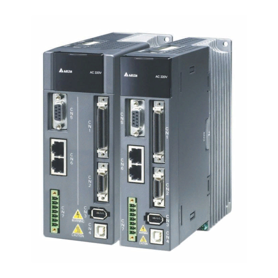
Page 9: The Interface Of Delta Ethercat Servo Drive
Run indicator (RUN) Link/Activity of EtherCAT EtherCAT output output port indicator (L/A) port (CN6) Error indicator (ERR) Figure 1 The Interface of Delta EtherCAT Servo Drive EtherCAT® is registered trademark and patented technology, licensed by Beckhoff Automation GmbH, Germany. Revision April, 2015... -
Page 10: Led Indicators
Chapter 1 CoE Drive Overview ASDA A2-E 1.3 LED Indicators Indicator Indicator pattern state Blinking 200ms 200ms Single Flash 1000ms 200ms Figure 2. RJ45 LED indicator pattern ERROR (ERR) LED The ERR LED indicator shows the error status of EtherCAT communication. - Page 11 The synchronization of Master Clock and Slave Clock is failed. SyncManager error: The data of process data is lost when receiving. PDI Watchdog The hardware failure on slave. Please contact Delta distributors for timeout: assistance. RUN LED The RUN LED indicator shows the status of EtherCAT state machine...
- Page 12 Chapter 1 CoE Drive Overview ASDA A2-E Link Activity (L/A) LED The L/A LED indicator shows the physical link status and the link activity. Indicator state Slave State No link Blinking Link and activity Link without activity No link: The link has not established yet.
-
Page 13: The Topology
1.4 The Topology The topology is defined by the host controller. Please refer to the host controller’s application manual. There are only one input port and one output port on Delta servo drive for EtherCAT communication ports. Figure 3 EtherCAT connection topology example... -
Page 14: Wiring
Chapter 1 CoE Drive Overview ASDA A2-E 1.5 Wiring I/O Signal (CN1) Connection and Connector Terminal Layout In order to have a more flexible communication with the master, 4 programmable Digital Output (DO) and 7 programmable Digital Input (DI) are provided, which are parameter P2-18~P2-21 and P2-10~P2-16 respectively. -
Page 15: Explanation Of I/O (Cn1) Connector Signal
ASDA A2-E Chapter 1 Coe Drive Overview 1.5.1 Explanation of I/O (CN1) Connector Signal The following details the signals listed in previous section. General Signals Wiring Method Signal Name Pin No Function (Refer to 3.4.3) Position pulse C13/C14 Encoder signal output A, B, Z (Line Driver output) -
Page 16: Cn2 Connector
Chapter 1 CoE Drive Overview ASDA A2-E 1.5.2 CN2 Connector CN2 Connector (male) CN2 Connector (female) Rear view Quick Connector Military Connector HOUSING: AMP (1-172161-9) 3106A-20-29S Drive Connector Motor Connector Military Quick Terminal Pin No Function and Description Color Symbol... -
Page 17: Cn5 Connector (Full-Closed Loop)
ASDA A2-E Chapter 1 Coe Drive Overview 1.5.3 CN5 Connector (Full-closed Loop) Connect linear scale or encoder (A, B, Z format) to the servo and form a full-closed loop. In position mode, the pulse command issued by the controller is based on the control loop of the external linear scale. -
Page 18: Cn6 Ethercat Terminal
Chapter 1 CoE Drive Overview ASDA A2-E 1.5.4 CN6 EtherCAT Terminal CN5 Connector (female) Pin No Signal Name Terminal Symbol Function and Description TX + TX + Transmit + TX - TX - Transmit - RX + RX + Receive +... -
Page 19: Cn7 Extension Di
ASDA A2-E Chapter 1 Coe Drive Overview 1.5.5 CN7 Extension DI CN7 Connector (male) Pin No Signal Name Terminal Symbol Function and Description VDD (24V) power is the same as COM+ the voltage of Pin11 in CN1 24V power Extension DI9... -
Page 20: Cn-Sto
Chapter 1 CoE Drive Overview ASDA A2-E 1.5.6 CN-STO CN-STO Connector (male) Pin No Signal Name Terminal Symbol Function and Description VDD24V VDD (24V) power is the same COM+ as the voltage of Pin11 in CN1 power STO_A STO_A STO input pin A+... -
Page 21: Sto With Safety Relay
ASDA A2-E Chapter 1 Coe Drive Overview 1.5.7 STO with Safety Relay COM+ ESTOP STO_A 24V DC / STO_A Safety Relay STO_B / STO_B FDBK_A FDBK_B COM- 1.5.8 STO Disable COM+ STO_A / STO_A STO_B / STO_B FDBK_A FDBK_B COM-... -
Page 22: Dimension
Chapter 1 CoE Drive Overview ASDA A2-E 1.6 Dimension 1.6.1 220V Series 100W/200W/400W Weight 1.5(3.3) 750W/1kW/1.5kW Weight 2.0(4.4) 1-15 Revision April, 2015... - Page 23 ASDA A2-E Chapter 1 Coe Drive Overview 2kW/3kW < 0.7 Weight 2.89(6.36) 14.5 TERMINIAL 1-16 Revision April, 2015...
-
Page 24: Series
Chapter 1 CoE Drive Overview ASDA A2-E 1.6.2 400V Series 400W/750W/1kW/1.5kW Weight 2.0(4.4) 12.5 2kW/3kW/4.5kW/5.5kW 123.5 205.5 70.2 Weight 4.6(10.1) 1-17 Revision April, 2015... - Page 25 ASDA A2-E Chapter 1 Coe Drive Overview 7.5kW 119.5 70.2 205.5 Weight 4.6(10.1) PE TERMINAL NOTE 1. Dimensions are in millimeters (inches); Weights are in kilograms (kg) and pounds (lbs). 2. Dimensions and weights of the servo drive may be revised without prior notice.
-
Page 26: Chapter 2 System Setup
Chapter 2 System Setup 2.1 Parameter Settings of EtherCAT Mode 1. Set parameter P1-01 to 0x0C for EtherCAT communication and CANopen as the application layer. 2. Restart the system of servo drive. Address:0102H P1-01● Control Mode and Output Direction 0103H Interface:... - Page 27 ASDA A2-E Chapter 2 System Setup PR: Position control mode. The command is from the internal signal. Execution of 64 positions is via DI.POS0 ~ POS5. A variety of homing control is also provided. S: Speed control mode. The command is from the external signal or internal signal. Execution of the command selection is via DI.SPD0 and DI.SPD1.
-
Page 28: Twincat Setup
A lot of software can be applied to configure EtherCAT system. The following procedures are the example of TwinCAT of Beckhoff. Please install the software properly before you start to configure the system. Copy Delta XML description to the folder the TwinCAT installed (usually C:\TwinCAT\Io\EtherCAT). Restart the TwinCAT. - Page 29 ASDA A2-E Chapter 2 System Setup Figure 5 Select the correct Adapter from the devices (NICs) installed in the computer for EtherCAT communication and click “Install”. Figure 6 Revision April, 2015...
- Page 30 Chapter 2 System Setup ASDA A2-E Open a new project from the drop down menu File → new. Right click I/O Devices and select Scan Devices or Press <F5> to scan the devices. Click OK in the pop-up dialog window to confirm the information.
- Page 31 Figure 11 Click No and TwinCAT will be switched to Config mode. Figure 12 TwincAT is in Config Mode. In the left panel, it shows Device (EtherCAT) and you can find ASDA A2-E CoE Drive. Figure 13 Revision April, 2015...
- Page 32 Chapter 2 System Setup ASDA A2-E Select the Drive (ASDA A2-E) and in Online tab you can check if the device’s EtherCAT state machine (ESM) is in PREOP state. Figure 14 13. Double click on Drive (ASDA A2-E CoE Drive) and it will show: 2nd TxPDO –...
- Page 33 ASDA A2-E Chapter 2 System Setup 14. Set the communication cycle* and the default value is 2ms. Select NC-Task 1 SAF in the left window, and set Cycle ticks as communication cycle (The minimum value is 1ms) in the right window.
- Page 34 Chapter 2 System Setup ASDA A2-E 16. Switch TwinCAT to Run Mode. to generate Mappings → press to check confiugration → and Press press to activate configuration. TwinCAT will be switched to Run Mode and then click OK in pop-up dialog.
- Page 35 ASDA A2-E Chapter 2 System Setup 18. In Online tab, there are two different speed levels of jogging buttons for forward and backward movement which can test the system. During the operation, please Be Ensured that the movement would not damage your system and endanger the personnel safety.
-
Page 36: Synchronization Modes Setting
2.3 Synchronization Modes Setting 2.3.1 Two Synchronization Modes of Delta Servo ASDA A2-E supports two synchronization modes, Free Run mode and DC- Synchronous mode. Please note that the asynchronous Free Run mode is still under the definition of “Synchronization Modes” within EtherCAT specification guide. -
Page 37: Select The Synchronization Mode
Chapter 2 System Setup 2.3.2 Select the Synchronization Mode 1. Select Drive (ASDA A2-E CoE Drive) in the left window. 2. The DC tab in the right window, users can select DC-Synchronous or Free Run as the Operation Mode. This is for selecting synchronous or asynchronous mode. - Page 38 Chapter 2 System Setup ASDA A2-E The unit of cycle for SYNC0 cycle time is 1ms. 1ms (PDO cycle time = 1ms) 2ms (PDO cycle time = 2ms) SYNC0 cycle time supported 3ms (PDO cycle time = 3ms) … * SYNC0 cycle time is used to define PDO cycle time.
-
Page 39: Pdo Mapping
0x1A00 to 0x1A03 for TxPDOs in Object Dictionary. 2.4.1 Default PDO Mappings The following tables are the default PDO mappings of ASDA A2-E CoE Drive for cyclic data exchange and are also defined in EtherCAT Slave Information file (XML file). -
Page 40: Re-Define A Pdo Mapping
Chapter 2 System Setup ASDA A2-E 4 PDO Mapping RxPDO Control Word Target Torque (0x1603) (0x6040) (0x6071) TxPDO Status Word Actual Position Actual Torque (0x1A03) (0x6041) (0x6064) (0x6077) 2.4.2 Re-define a PDO Mapping Setup procedure 1. Set 【RxPDO Assignment:0x1C12:0/ TxPDO Assignment: 0x1C13:0】to 0x0 for disabling the PDO assignment. -
Page 41: Using Twincat
Shift and F4 to set/reset TwinCAT to Config Mode (Click OK in pop-up dialog). 2. Select Drive (ASDA A2-E CoE Drive) in the left window. In Process Data field, you can change PDO Assignment for another PDO mapping. 3. Right click the PDO Content Window, and find the PDO mapping that you desire to set, and then you can configure (Insert/Delete/Edit/Move Up/Move Down) the PDO mapping content. - Page 42 Chapter 2 System Setup ASDA A2-E 4. After changing the PDO Assignment, press or F4 to reload I/O devices. (Click No in pop-up dialog and stay in Config Mode.) 2-17 Revision April, 2015...
- Page 43 ASDA A2-E Chapter 2 System Setup (This page is intentionally left blank.) 2-18 Revision April, 2015...
- Page 44 Chapter 3 EtherCAT Communication States ASDA A2-E supports four EtherCAT communication states which are shown as below: Init (Initialization) Pre-Operational Safe-Operational Operational Init (IP) (PI) Pre-operational (SI) (OI) (PS) (SP) (OP) Safe-operational (SO) (OS) Operational Figure 29 The EtherCAT State machine EtherCAT host controller can switch the states.
-
Page 45: Chapter 3 Ethercat Communication States
Chapter 3 EtherCAT Communication States ASDA A2-E Except SDO, for accessing Mailbox, the PDO (Process Data Object) Safe-Operational can only be applied for Process Data Input (TxPDO) at this stage. The full function of SDO and PDO (TxPDO and RxPDO) are available Operational now. -
Page 46: Chapter 4 Ethercat Troubleshooting
Chapter 4 EtherCAT Troubleshooting Q: Why my TwinCAT cannot find EtherCAT Device from all installed NIC (Network Interface Card) and only shows RT-Ethernet devices? 1. Please refer to TwinCAT setup procedure and make sure NIC is installed properly. 2. Check if the cable is correctly connected and L/A LED is lit. Q: The dialog shows “Unknown device type found”... - Page 47 3. Download and click OK in pop-up dialog. Figure 32 Q: ASDA A2-E servo drive shows AL185 This alarm message occurs because of the disconnection of EtherCAT cable between the host and the slave. Please check the wiring. After checking the connection of the cable, it is necessary to re-servo on the drive or set OD 0x6040 to 0x86 for fault reset.
- Page 48 Working under Operational state and losing three consecutive PDOs will lead to this alarm. 1. A mechanism inside Delta Servo Drive can be used to monitor the error when receiving PDO by setting P0-02 to 121. If the number keeps increasing, it can be interpreted as the exaggerated jitter of PDO or server interference on the communication cable.
- Page 49 ASDA A2-E Chapter 4 EtherCAT Troubleshooting (This page is intentionally left blank.) Revision April, 2015...
-
Page 50: Chapter 5 Canopen Operation Mode
Chapter 5 CANopen Operation Mode 5.1 Profile Position Mode 5.1.1 Description Servo drive (hereinafter referred to as “Drive”) receives position command from the host (external) controller (hereinafter referred to as “Host”) and then controls servo motor to reach the target position. Pulse of User-defined Unit Definition: Pulse of User Unit (PUU): No. -
Page 51: Advanced Setting Procedures
Chapter 5 CANopen Operation Mode ASDA A2-E 5.1.3 Advanced Setting Procedures 1. Host could obtain more information about profile position mode. Read 【Position demand value:6062 】to obtain the internal position command. (unit: PUU) Read 【Position actual value*:6063 】to obtain the actual position value. (unit: increments) 2. -
Page 52: Associated Object List
ASDA A2-E Chapter 5 CANopen Operation Mode accepted position range position position window position window position reached position not reached position not reached target position Position reached 5.1.4 Associated Object List Index Name Type Attr. 6040 Controlword UNSIGNED16 6041 Statusword... -
Page 53: Interpolation Position Mode
Chapter 5 CANopen Operation Mode ASDA A2-E 5.2 Interpolation Position Mode 5.2.1 Description The Host sends PDO periodically. With each PDO, the Host sends the next reference Xi, differece△X and controlword to the drive. While the next SYNC0 is receiving, the drive interpolates from ... -
Page 54: Operation Procedures
ASDA A2-E Chapter 5 CANopen Operation Mode 5.2.2 Operation Procedures 1. Set 【Mode of operations:6060 】to interpolation position mode(0x07). 2. Set 【Interpolation sub mode select:60C0 】to Interpolation mode. If 60C0 is [0], the Host does not send [60C1 Sub-2]. It could save calculating time of the host and the Drive could also work. -
Page 55: Cyclic Synchronous Position Mode
Chapter 5 CANopen Operation Mode ASDA A2-E 5.3 Cyclic Synchronous Position Mode 5.3.1 Description The Host plans the path in Cyclic Synchronous Position mode and sends PDO periodically. With each PDO, the Host sends the target position and controlword to the drive. -
Page 56: Associated Object List
ASDA A2-E Chapter 5 CANopen Operation Mode 3. Drive PDO Rx: 607A for Target Pos Cmd (32-bit). 6040 Sub-0 for ControlWord. 5.3.4 Associated Object List Index Name Type Attr. 6040 Controlword UNSIGNED16 6041 Statusword UNSIGNED16 6060 Modes of operation... -
Page 57: Homing Mode
Chapter 5 CANopen Operation Mode ASDA A2-E 5.4 Homing Mode 5.4.1 Description This mode could help the drive to find the home position. Users can specify the speed, acceleration and method of homing. 5.4.2 Operation Procedures 1. Set【Mode of operations:6060h】to the homing mode(0x06). -
Page 58: Associated Object List
ASDA A2-E Chapter 5 CANopen Operation Mode 5.4.3 Associated Object List Index Name Type Attr. 6040h Controlword UNSIGNED16 6041h Statusword UNSIGNED16 6060h Modes of operation INTEGER8 6061h Modes of operation display INTEGER8 607Ch Home offset INTEGER32 6093h Position factor UNSIGNED32... -
Page 59: Profile Velocity Mode
Chapter 5 CANopen Operation Mode ASDA A2-E 5.5 Profile Velocity Mode 5.5.1 Description The drive could receive velocity command and plan acceleration and deceleration. 5.5.2 Operation Procedures 1. Set【Mode of operations:6060h】to profile velocity mode(0x03). 2. Set【Controlword:6040h】as (0x06 0x07 0x0F) to Servo ON the drive and enable the motor. -
Page 60: Advanced Setting Procedures
ASDA A2-E Chapter 5 CANopen Operation Mode 5.5.3 Advanced Setting Procedures 1. Host could obtain the information of velocity mode. 】to inquire the internal velocity command. Read【Velocity demand value:606B (unit: 0.1rpm) 】to obtain the actual velocity value. (unit: ... -
Page 61: Cyclic Synchronous Velocity Mode
Chapter 5 CANopen Operation Mode ASDA A2-E 5.6 Cyclic Synchronous Velocity Mode 5.6.1 Description The Host plans the path in Cyclic Synchronous Velocity mode. In this mode, the Host sends PDO periodically including target position and controlword to drive. In addition, velocity offset and torque offset can be used as the velocity and torque feedforwad. -
Page 62: Associated Object List
ASDA A2-E Chapter 5 CANopen Operation Mode 3. Drive PDO Rx: 60F F for Target Velocity Cmd (32-bit) 6040 Sub-0 for ControlWord 5.6.4 Associated Object List Index Name Type Attr. 6040 Controlword UNSIGNED16 6041 Statusword UNSIGNED16 6060 Modes of operation... -
Page 63: Profile Torque Mode
Chapter 5 CANopen Operation Mode ASDA A2-E 5.7 Profile Torque Mode 5.7.1 Description The drive could receive torque command and plan profile torque slope. 5.7.2 Operation Procedures 1. Set 【Mode of operations:6060h】to profile torque mode(4). 2. Set 【Controlword:6040h】as (0x6 0x7 0x0F) to Servo ON the drive and enable the motor. -
Page 64: Associated Object List
ASDA A2-E Chapter 5 CANopen Operation Mode Read 【Current actual value:6078 】to obtain the instantaneous current in servo motor. (unit: one rated torque in a thousand) 5.7.4 Associated Object List Index Name Type Attr. 6040 Controlword UNSIGNED16 6041 Statusword... -
Page 65: Cyclic Synchronous Torque Mode
Chapter 5 CANopen Operation Mode ASDA A2-E 5.8 Cyclic Synchronous Torque Mode 5.8.1 Description The Host plans the path in Cyclic Synchronous Torque mode. In this mode, the Host sends PDO periodically including target position and controlword to drive. In addition, velocity offset and torque offset can be used as the velocity and torque feedforwad. -
Page 66: Associated Object List
ASDA A2-E Chapter 5 CANopen Operation Mode 5.8.4 Associated Object List Index Name Type Attr. 6040 Controlword UNSIGNED16 6041 Statusword UNSIGNED16 6060 Modes of operation INTEGER8 6061 Modes of operation display INTEGER8 6071 Target torque INTEGER16 60B2 Torque offset INTEGER16... -
Page 67: Limit Position Handling Procedure
Chapter 5 CANopen Operation Mode ASDA A2-E 5.9 Limit Position Handling Procedure 5.9.1 Description Drive will switch to Quick-Stop status while traveling to the position of positive or negative limit sensors, and it can be handled by the following procedures. -
Page 68: Touch Probe Function
ASDA A2-E Chapter 5 CANopen Operation Mode 5.10 Touch Probe Function 5.10.1 Description Touch Probe function can be enabled by the DI on CN7 or the encoder; among that, the feedback position can be latched as positive or negative edge with DI13 on CN7. -
Page 69: Touch Probe Status
Chapter 5 CANopen Operation Mode ASDA A2-E Trigger with zero impulse signal Reserved Switch off sampling at positive edge of touch probe 2 Enable sampling at positive edge of touch probe 2 Switch off sampling at negative edge of touch... -
Page 70: Associated Object List
ASDA A2-E Chapter 5 CANopen Operation Mode Touch probe 2 has no negative edge value stored Touch probe 2 has negative edge value stored 11 ~ 13 Reserved Trigger with touch probe 2 input Trigger with zero impulse signal Toggle with every update of Touch probe 2 value Stored 5.10.4 Associated Object List... - Page 71 Chapter 5 CANopen Operation Mode ASDA A2-E (This page is intentionally left blank.) 5-22 Revision April, 2015...
-
Page 72: Chapter 6 Object Dictionary Entries
Chapter 6 Object Dictionary Entries 6.1 Specifications for Objects 6.1.1 Object Type Object Name Comments A single value such as an UNSIGNED8, Boolean, float, INTEGER16 etc. ARRAY A multiple data field object where each data field is a sample variable of the SAME basic data type e.g. -
Page 73: Overview Of Object Group 1000
Chapter 6 Object Dictionary Entries ASDA A2-E 6.2 Overview of Object Group 1000 Index Object Type Name Data Type Access 1000 device type UNSIGNED32 1001 error register UNSIGNED8 1600 RECORD Receive PDO mapping UNSIGNED32 1A00 RECORD Transmit PDO mapping UNSIGNED32 ※... -
Page 74: Overview Of Object Group 6000
ASDA A2-E Chapter 6 Object Dictionary Entries 6.3 Overview of Object Group 6000 Object Index Name Data Type Access Mappable Type 603F Error Code UNSIGNED16 6040 Controlword UNSIGNED16 6041 Statusword UNSIGNED16 605B Shutdown option code INTEGER16 605E Fault reaction option code... - Page 75 Chapter 6 Object Dictionary Entries ASDA A2-E Object Index Name Data Type Access Mappable Type 607C Home Offset INTEGER32 607D ARRAY Software position limit INTEGER32 607E Polarity UNSIGNED8 607F Max profile velocity UNSIGNED32 6080 Max motor speed UNSIGNED32 6081 Profile velocity...
- Page 76 ASDA A2-E Chapter 6 Object Dictionary Entries Object Index Name Data Type Access Mappable Type 60F2 Positioning option code UNSIGNED16 60F4 Following error actual value INTEGER32 60FC Position demand value INTEGER32 60FD Digital inputs UNSIGNED32 60FF Target velocity INTEGER32 6502...
-
Page 77: Details Of Objects
Chapter 6 Object Dictionary Entries ASDA A2-E 6.4 Details of Objects Object 1000 : Device Type INDEX 1000 Name device type Object Code Data Type UNSIGNED32 Access PDO Mapping Value Range UNSIGNED32 Default Value 04020192 : A2 Series Object 1001... - Page 78 ASDA A2-E Chapter 6 Object Dictionary Entries PDO Mapping Value Range 0: deactivated 1~8: activated Default Value Sub-Index Description PDO mapping for the nth application object to be mapped Data Type UNSIGNED32 Access PDO Mapping Value Range UNSIGNED32 Default Value...
- Page 79 Chapter 6 Object Dictionary Entries ASDA A2-E Access PDO Mapping Value Range 0: deactivated 1~8: activated Default Value Sub-Index Description PDO mapping for the nth application object to be mapped Data Type UNSIGNED32 Access PDO Mapping Value Range UNSIGNED32 Default Value...
- Page 80 ASDA A2-E Chapter 6 Object Dictionary Entries Value Range 1600 to 1603 Default Value 1601 Object 1C13 : TxPDO assign INDEX 1C13 Name TxPDO assign Object Code RECORD Data Type PDO Mapping assign Access PDO Mapping Sub-Index Description Number of assigned PDO mapping...
- Page 81 Chapter 6 Object Dictionary Entries ASDA A2-E Default Value Object 6040 : Controlword INDEX 6040 Name Controlword Object Code Data Type UNSIGNED16 Access PDO Mapping Value Range UNSIGNED16 Default Value P1-01 = 0x0C, Default is 0x0004 ControlWord (6040h) State Machine...
- Page 82 ASDA A2-E Chapter 6 Object Dictionary Entries Bit Definition 15~9 Quick Switch Operation mode Enable Enable Halt Fault reset Stop specific operation voltage (B-contact) Note: The user needs to set 6040h to 0x0006->0x0007->0x000F for Servo On step by step. Operation mode...
- Page 83 Chapter 6 Object Dictionary Entries ASDA A2-E Object 6041 : Statusword INDEX 6041 Name Statusword Object Code Data Type UNSIGNED16 Access PDO Mapping Value Range UNSIGNED16 Default Value Data Description Bit Definition Ready to switch on Switch on Operation enabled (status of servo on)
- Page 84 ASDA A2-E Chapter 6 Object Dictionary Entries Object 605B : Shutdown option code INDEX 605B Name Shutdown option code Object Code Data Type INTEGER16 Access PDO Mapping Value Range INTEGER16 Default Value Comment 0:Disable drive function -1:Dynamic break enable Object 605E...
- Page 85 Chapter 6 Object Dictionary Entries ASDA A2-E 4: Profile torque mode 6: Homing mode 7: Interpolated position mode 8: Cyclic synchronous position mode 9: Cyclic synchronous velocity mode 10: Cyclic synchronous torque mode Object 6061 : Modes of operation display...
- Page 86 ASDA A2-E Chapter 6 Object Dictionary Entries Default Value Comment Unit: increments Object 6064 : Position actual value INDEX 6064 Name Position actual value Object Code Data Type INTEGER32 Access PDO Mapping Value Range INTEGER32 Default Value Comment Unit: PUU...
- Page 87 Chapter 6 Object Dictionary Entries ASDA A2-E Object 6068 : Position window time INDEX 6068 Name Position window time Object Code Data Type UNSIGNED16 Access PDO Mapping Value Range UNSIGNED16 Default Value Comment Unit: millisecond Object 606B : Velocity demand value...
- Page 88 ASDA A2-E Chapter 6 Object Dictionary Entries Object 606D : Velocity window INDEX 606D Name Velocity window Object Code Data Type INTEGER16 Access PDO Mapping Value Range 0~3000 Default Value Comment Unit: 0.1rpm Object 606E : Velocity window time INDEX...
- Page 89 Chapter 6 Object Dictionary Entries ASDA A2-E Object 6071 : Target torque INDEX 6071 Name Target torque Object Code Data Type INTEGER16 Access PDO Mapping Value Range -3000~3000 Default Value Comment Unit: one rated torque in a thousand Object 6072...
- Page 90 ASDA A2-E Chapter 6 Object Dictionary Entries Object 6075 : Motor rated current INDEX 6075 Name Motor rated current Object Code Data Type UNSIGNED32 Access PDO Mapping Value Range UNSIGNED32 Comment Unit: milliamp Object 6076 : Motor rated torque INDEX...
- Page 91 Chapter 6 Object Dictionary Entries ASDA A2-E PDO Mapping Value Range INTEGER16 Comment Unit: one rated current in a thousand Object 607A : Target position INDEX 607A Name Target position Object Code Data Type INTEGER32 Access PDO Mapping Value Range...
- Page 92 ASDA A2-E Chapter 6 Object Dictionary Entries Object 607D : Software position limit INDEX 607D Name Software position limit Object Code ARRAY Data Type INTEGER32 Access PDO Mapping Sub-Index Description Number of entries Data Type UNSIGNED8 Access PDO Mapping Value Range...
- Page 93 Chapter 6 Object Dictionary Entries ASDA A2-E Object 607F : Max profile velocity INDEX 607F Name Max profile velocity Object Code Data Type UNSIGNED32 Access PDO Mapping Value Range UNSIGNED32 Default Value P1-55(rpm) * 10 Comment Unit:0.1rpm Object 6080 : Max motor speed...
- Page 94 ASDA A2-E Chapter 6 Object Dictionary Entries Object 6083 : Profile acceleration INDEX 6083h Name Profile acceleration Object Code Data Type UNSIGNED32 Access PDO Mapping Value Range 1~UNSIGNED32 Default Value Comment For Profile position mode 6060h=1 & Profile velocity mode 6060h = 3...
- Page 95 Chapter 6 Object Dictionary Entries ASDA A2-E Object 6086 : Motion profile type INDEX 6086 Name Motion profile type Object Code Data Type INTEGER16 Access PDO Mapping Value Range INTEGER16 Default Value Object 6087 : Torque slope INDEX 6087 Name...
- Page 96 ASDA A2-E Chapter 6 Object Dictionary Entries PDO Mapping Value Range Default Value Sub-Index Description Numerator Data Type UNSIGNED32 Access PDO Mapping Default Value Comment Same as P1-44 Sub-Index Description Feed_constant Data Type UNSIGNED32 Access PDO Mapping Default Value Comment...
- Page 97 Chapter 6 Object Dictionary Entries ASDA A2-E Index Pulse Positive Limit Switch Method2:Homing on positive limit switch and index pulse Index Pulse Home Switch Method 3 and 4:Homing on positive home switch and index pulse 6-26 Revision April, 2015...
- Page 98 ASDA A2-E Chapter 6 Object Dictionary Entries Index Pulse Home Switch Method 5 and 6:Homing on negative home switch and index pulse Index Pulse Home Switch Positive Limit Switch Index Pulse Home Switch Negative Limit Switch Method 7 to 14:Homing on home switch and index pulse...
- Page 99 Chapter 6 Object Dictionary Entries ASDA A2-E Method 15 and 16:Reserved (no picture) Home Switch Method 17 to 30:Homing without an index pulse Method 31 and 32:Reserved (no picture) Index Pulse Method 33 to 34:Homing on index pulse Method 35:Homing on current position (no picture)
- Page 100 ASDA A2-E Chapter 6 Object Dictionary Entries Default Value Sub-Index Description Speed during search for switch Data Type UNSIGNED32 Access PDO Mapping Value Range 1~2000rpm Default Value Comment Unit:0.1rpm Sub-Index Description Speed during search for zero Data Type UNSIGNED32 Access...
- Page 101 Chapter 6 Object Dictionary Entries ASDA A2-E Object 60B0 : Position offset INDEX 60B0 Name Position offset Object Code Data Type INTEGER32 Access PDO Mapping Value Range INTEGER32 Default Value Comment Unit: PUU Object 60B1 : Velocity offset INDEX 60B1...
- Page 102 ASDA A2-E Chapter 6 Object Dictionary Entries Object 60B8 : Touch probe function INDEX 60B8 Name Touch probe function Object Code Data Type UNSIGNED16 Access PDO Mapping Value Range UNSIGNED16 Default Value Comment Object 60B9 : Touch probe status INDEX...
- Page 103 Chapter 6 Object Dictionary Entries ASDA A2-E Object 60BB : Touch probe pos1 neg value INDEX 60BB Name Touch probe pos1 neg value Object Code Data Type INTEGER32 Access PDO Mapping Value Range INTEGER32 Default Value Comment Unit: PUU Object 60BC...
- Page 104 INTEGER16 Default Value Comment 0: manufacturer specific (Linear interpolation -- no need the Pos Difference [OD- 60C1sub2]) -1: manufacturer specific ( Delta definition -- need pos difference [OD-60C1sub2]) Object 60C1 : Interpolation data record INDEX 60C1 Name Interpolation data record...
- Page 105 Chapter 6 Object Dictionary Entries ASDA A2-E Access PDO Mapping Value Range INTEGER32 Default Value Comment Unit: 32-bit CMD_PUU Sub-Index Description Velocity – Pos_Cmd difference Data Type INTEGER16 Access PDO Mapping Value Range INTEGER16 Default Value Comment △X = (X –...
- Page 106 ASDA A2-E Chapter 6 Object Dictionary Entries PDO Mapping Value Range UNSIGNED8 Default Value Sub-Index Description Interpolation time index Data Type INTEGER8 Access PDO Mapping Value Range -128~63 Default Value Object 60C5 : Max acceleration INDEX 60C5 Name Max acceleration...
- Page 107 Chapter 6 Object Dictionary Entries ASDA A2-E Object 60F2 : Positioning option code INDEX 60F2 Name Positioning option code Object Code Data Type UNSIGNED16 Access PDO Mapping Value Range UNSIGNED16 Default Value Object 60F4 : Following error actual value INDEX...
- Page 108 ASDA A2-E Chapter 6 Object Dictionary Entries Object 60FD : Digital inputs INDEX 60FD Name Digital inputs Object Code Data Type UNSIGNED32 Access PDO Mapping Value Range UNSIGNED32 Default Value Object 60FF : Target velocity INDEX 60FF Name Target velocity...
- Page 109 Chapter 6 Object Dictionary Entries ASDA A2-E Object 2xxx : Manufacturer parameter INDEX 2xxx Name Manufacturer parameter Object Code Data Type INTEGER16/INTEGER32 Access PDO Mapping Value Range NTEGER16/INTEGER32 Default Value Object 2xxx is defined to parameter. If users desire to use CANopen protocol for simulate Keypad press, they could read and write Keypad parameters via SDO protocol.
- Page 110 ASDA A2-E Chapter 6 Object Dictionary Entries : Electronic Gear 【P1-44】 Example 2: Object 212C INDEX 212C Name Electronic Gear Object Code Data Type INTEGER32 Access PDO Mapping Value Range INTEGER32 6-39 Revision April, 2015...
- Page 111 Chapter 6 Object Dictionary Entries ASDA A2-E (This page is intentionally left blank.) 6-40 Revision April, 2015...
- Page 112 Chapter 7 Safety Function (Safe Torque Off, STO) 7.1 Description of Terminal Block CN-STO Connector (male) Terminal Pin No Function and Description Symbol COM+ VDD (24V) power is identical to pin 5 of CN1 STO_A STO input pin A+ /STO_A STO input pin A- STO_B STO input pin B+...
- Page 113 ASDA A2-E Chapter 7 Safety Function (Safe Torque Off, STO) STO with safety relay: COM+ ESTOP STO_A 24V DC / STO_A Safety Relay STO_B / STO_B FDBK_A FDBK_B COM- STO Disable: COM+ STO_A / STO_A STO_B / STO_B FDBK_A FDBK_B...
- Page 114 Chapter 7 Safety Function (Safe Torque Off, STO) ASDA A2-E 7.1.1 Functional Safety Standard and Certificates Pleasee refer to Chapter 9. 7.2 STO Safety Function Fault Rate of Safety Function Item Definition Standard Features Channel 1: 80.08% Safe Failure Fraction IEC61508 Channel 2: 68.91%...
- Page 115 ASDA A2-E Chapter 7 Safety Function (Safe Torque Off, STO) (1) Status Description of STO Alarm: See the figure below. When the motor runs properly (SERVO ON), if STO_A and STO_B signal (which is also called safety signal) is lost for 10 ms at the same time, AL500 occurs.
- Page 116 Chapter 7 Safety Function (Safe Torque Off, STO) ASDA A2-E 7.3 Related Parameter Descriptions of STO Function Through the setting of P2-93, users can determine FDBK status and if FDBK will latch when STO alarm occurs. Please refer to the following figure for the setting of P2-93:...
- Page 117 ASDA A2-E Chapter 7 Safety Function (Safe Torque Off, STO) 2. After the FDBK status restores, alarms can be cleared by normal corrective actions. In this case, AL500 can be cleared by DI: Alm Reset. Example of No Latch: If Logic C P2-93 = XX12 is set, the FDBK status will be close when the safety signal is lost and AL005 occurs.
- Page 118 Chapter 7 Safety Function (Safe Torque Off, STO) ASDA A2-E AL500: STO Function is enabled Causes Checking Method Corrective Actions Safety function (STO) is Safety function (STO) is enabled. DI.ARST or write 0 into P0-01 or enabled Please check the causes.
- Page 119 ASDA A2-E Chapter 7 Safety Function (Safe Torque Off, STO) (This page is intentionally left blank.) Revision April, 2015...
- Page 120 Chapter 8 Alarm List EtherCAT Communication Fault Messages Emergency Object Byte Emergency Error Error Content Panel Alarm Code Code register Fault Messages (If ALARM code is not showed here, please refer to the User Manual) Display Fault Name Fault Description Clearing Method Communication AL185...
- Page 121 ASDA A2-E Chapter 8 Alarm List CANopen PDO The specified object in the message is object is write- AL127 6040h fault reset write-protected (cannot be changed) when protected when Servo On. Servo On. Error occurs when An error occurs when loading the default reading CANopen settings from EEPROM at start-up.
- Page 122 Chapter 8 Alarm List ASDA A2-E SYNC period error Object 0x1006 data error. SYNC period AL3E5 6040h fault reset (Servo Off) 1006h value is invalid. 6040h fault reset The safety function (STO) is enabled. Safe torque off AL500 STO_A and STO_B change state (Servo Off) simultaneously.
- Page 123 ASDA A2-E Chapter 8 Alarm List Error Code Table 32bit-ErrorCode Display Description (16bit-ErrorCode + 16bit-Additional Info) AL001 Overcurrent 2310-0001 AL002 Overvoltage 3110-0002 AL003 Undervoltage 3120-0003 AL004 Motor error 7122-0004 AL005 Regeneration error 3210-0005 AL006 Overload 3230-0006 AL007 Overspeed 8400-0007 AL008...
- Page 124 Chapter 8 Alarm List ASDA A2-E AL030 Motor protection error 7121-0030 AL031 U,V,W wiring error 3300-0031 AL040 Full-closed loop excessive deviation 8610-0040 AL099 DSP firmware upgrade 5500-0099h AL201 CANopen Data Initial Error 6310-0201 AL283 Forward software limit 5444-0283 AL285 Reverse software limit...
- Page 125 ASDA A2-E Chapter 8 Alarm List AL3E4 CANopen IP command failed (Servo Off) 6200-03E4 AL3E5 SYNC period error (Servo Off) 6200-03E5 AL500 Safe torque off (Servo Off) 9000-0500 AL501 STO_A lost (Servo Off) 9000-0501 AL502 STO_B lost (Servo Off) 9000-0502...
- Page 126 Chapter 8 Alarm List ASDA A2-E SDO Error Message Abort Codes Abort Code Description 05040001 Client/server command specifier not valid or unknown 06010002 Attempt to write a read-only object 06020000 Object does not exist in the object dictionary 06040041 Object cannot be mapped to PDO...
- Page 127 ASDA A2-E Chapter 8 Alarm List (This page is intentionally left blank.) Revision April, 2015...
- Page 128 Chapter 9 Reference 1. CANopen Application Layer and Communication Profile, CiA Draft Standard 301, Version 4.02, Date: 13 February 2002 2. CANopen Device Profile Drives and Motion Control, CiA Draft Standard Proposal 402, Version 2.0, Date: 26 July 2002 Revision April, 2015...
- Page 129 EC Type-Examination Certificate Reg.-No.: 01/205/5429.00/15 Product tested Safety Function “Safe Torque Certificate Delta Electronics, Inc. Off” (STO) holder 18 Xinglong Road Taoyuan County Taoyuan City 33068 Taiwan, R.O.C. Type designation within the drive series VFD-C, VFD-CP, VFD-CT, VFD-CH, VFD-HH, DPD, VFD-ED-S and ASD-A2.