Sign In
Upload
Manuals
Brands
Xerox Manuals
Printer
DocuPrint N3225
Xerox DocuPrint N3225 Manuals
Manuals and User Guides for Xerox DocuPrint N3225. We have
6
Xerox DocuPrint N3225 manuals available for free PDF download: Service Manual, System Administrator Manual, User Manual, Product Reference Manual, Brochure, Supplementary Manual
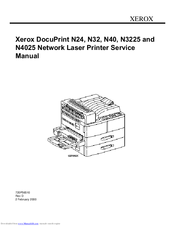
Xerox DocuPrint N3225 Service Manual (1032 pages)
Network Laser Printer
Brand:
Xerox
| Category:
Printer
| Size: 6.94 MB
Table of Contents
Introduction
6
Table of Contents
6
Organization
7
Printer Specifications
7
Revision Control List
8
Service Call Procedures
15
Call Flow Diagram
16
Initial Actions
17
Corrective Actions
17
Final Actions
18
Section 2 Printer Specifications
19
Printer Specifications
19
Electrical Specifications
21
Laser
21
Power On/Off
21
Power Saver
21
Power Sources and Consumption
21
Mechanical Specifications
22
Standard Configuration
23
Physical Location
24
Consumables
24
Status Display/Controls
24
Functional Specifications
25
General Information
25
Printing Speed for First Sheet out
25
Continuous Printing Speed (CPS) after First Sheet out
26
CPS after First Sheet out (N24)
26
CPS after First Sheet out (N32/N3225)
26
CPS after First Sheet out (N40/N4025)
27
Continuous Printing Speed (CPS) after First Sheet out
28
CPS after First Sheet out (N24)
28
CPS after First Sheet out (N40/N4025)
29
Environment
30
Safety Standards
30
Options
31
Printer Options
31
Paper Specifications
32
Special Media Used with N24/N32/N40/N3225/N
32
Approved Media Certified on the
33
Printer Family
33
Paper Tray Capacity
35
Multisheet Bypass Feeder [MBF] (Standard)
35
Trays 1 and 2 (Standard)
35
Envelope Feeder (Option)
36
High Capacity Feeder [HCF] (Option)
36
Paper Limitations
37
Paper Output Devices & Support Paper Specifications
38
Face down bin (Standard)
38
Offset Unit (Standard)
38
Duplex Module (Option)
39
Face up bin (Standard)
39
Mailbox (Option)
39
Finisher (Option)
39
Operating Language and Emulation
39
Communication Interfaces
40
Print Alignment Specification
40
Section 3 Parts Lists
41
Parts Lists
41
PL 1.1 Top Cover Assembly
44
PL 1.2 Front Cover
46
PL 1.3 Rear, Left, and Right Covers
48
PL 2.1 Tray Unit (1 of 2)
50
PL 2.2 Tray Unit (2 of 2)
52
PL 3.1 Tray Interface - Tray 1
54
PL 3.2 Paper Pick up - Tray 1
56
PL 3.3 Retard and Take Away - Tray 1
58
PL 3.4 Tray Interface - Tray 2
60
PL 3.5 Paper Pick up - Tray 2
62
PL 3.6 Retard and Take Away - Tray 2
64
PL 3.7 Feed Drive Transmission
66
PL 4.1 Multi-Sheet Bypass Feeder (MBF) / Duplex Support
68
PL 4.2 Multi-Sheet Bypass Feeder Assembly
70
PL 4.3 MBF Upper Feeder Assembly
72
PL 4.4 MBF Tray Assembly
74
PL 5.1 Tray 1 Frame and Left Cover
76
PL 5.2 Tray 2 Frame and Left Cover
78
PL 6.1 Registration
80
PL 6.2 Left Upper Cover Assembly
82
PL 6.3 Transport Chute Assembly
84
PL 7.1 Laser Assembly
86
PL 7.2 Xerography and Development
88
PL 8.1 Fuser Assembly
90
PL 9.1 Exit Lower Chute
92
PL 9.2 Offset Roller
94
PL 9.3 Exit Upper Chute Assembly
96
PL 9.4 Exit Drive Assembly
98
PL 10.1 Main Drive Assembly
100
PL 10.2 Fuser Drive Assembly
102
PL 11.1 Power Inlet and LVPS
104
PL 11.2 HVPS and Printer Engine Controller PWB
106
PL 11.3 System Controller Assembly
108
PL 12.1 Part Number Locator Listing
110
Section 4 Repair Procedures
115
Repair Procedures
115
Overview
118
REP 4.1 Covers
119
REP 4.1.1 Fuser Full Cover
119
REP 4.1.2 Top Cover Assembly
121
REP 4.1.3 Upper Rear Cover Assembly
123
REP 4.1.4 Lower Rear Cover
124
REP 4.1.5 Right Cover
125
REP 4.1.6 Left Upper Cover Assembly
126
REP 4.1.7 Control Panel
128
REP 4.2 Tray
129
REP 4.2.1 Tray 1 Lift up Motor
129
REP 4.2.2 Tray 2 Lift up Motor
130
REP 4.2.3 Tray 1 Feed Clutch
131
REP 4.2.4 Tray 2 Feed Clutch
132
REP 4.2.5 Tray 1 & 2 Feed Roll, Nudger Roll, and Retard Roll
133
REP 4.2.6 Tray 1 Take Away Roll and Retard Assembly
135
REP 4.2.7 Tray 2 Take Away Roll and Retard Assembly
145
REP 4.2.8 Tray 1 & 2 Lift up Sensor
148
REP 4.2.9 Tray 1 & 2 no Paper Sensor
149
REP 4.2.10 Tray 1 & 2 Size Switch Assembly
150
REP 4.2.11 Tray 1 Feeder Assembly
151
REP 4.2.12 Tray 2 Feeder Assembly
153
REP 4.3 Multisheet Bypass Feeder (MBF) Assembly
155
REP 4.3.1 MBF Assembly
155
REP 4.3.2 MBF Tray Assembly
156
REP 4.3.3 MBF Feed Roll
158
REP 4.3.4 MBF Nudger Roll
160
REP 4.3.5 MBF Pad
162
REP 4.3.6 MBF no Paper Sensor Assembly
164
REP 4.3.7 MBF Feed Clutch
166
REP 4.4 Registration
169
REP 4.4.1 Registration Clutch
169
REP 4.4.2 Registration Sensor
170
REP 4.4.3 Registration Roller Assembly
171
REP 4.5 Xerographics
173
REP 4.5.1 EP Cartridge
173
REP 4.5.2 BTR (Bias Transfer Roll)
175
REP 4.5.3 Charge Bias Assembly
176
REP 4.6 Laser
178
REP 4.6.1 Laser Assembly
178
REP 4.7 Fuser Assembly
180
REP 4.7.1 Fuser Assembly
180
REP 4.7.2 Fuser Drive Assembly
182
REP 4.7.3 Fuser Exit Sensor
184
REP 4.8 Offset / Exit Assembly
185
REP 4.8.1 Offset / Exit Assembly
185
REP 4.8.2 Exit Drive Assembly
187
REP 4.8.3 Face up Exit Sensor
188
REP 4.8.4 Exit Gate Solenoid
189
REP 4.8.5 Stack Full Sensor
190
REP 4.8.6 Offset Motor
191
REP 4.9 Main Drive
192
REP 4.9.1 Main Drive Assembly
192
REP 4.10 Electronics
196
REP 4.10.1 Main Switch
196
REP 4.10.2 LVPS Assembly
197
REP 4.10.3 AC Driver PWB
199
REP 4.10.4 HVPS Assembly
201
REP 4.10.5 Upper Left Cover Interlock Switch Assembly
203
REP 4.10.6 Printer Engine Controller PWB
205
REP 4.10.7 System Controller PWB
207
REP 4.10.8 System Controller PWB Cover
208
REP 4.10.9 System Controller Interface PWB
209
REP 4.10.10 Toner Sensor
211
REP 4.10.11 EP Cartridge Interlock Switch
213
REP 4.10.12 Noise Filter PWB
214
ADJ 4.1 Overall Lead Edge Registration - Simplex
215
ADJ 4.2 Individual Lead Edge Registration - Simplex
216
ADJ 4.3 Overall Lead Edge Registration - Duplex
218
ADJ 4.4 Overall Side Edge Registration - Simplex
220
ADJ 4.5 Individual Side Edge Registration - Simplex
222
ADJ 4.6 Overall Side Edge Registration - Duplex
224
ADJ 4.7 Individual Side Edge Registration - Duplex
226
Section 5 General Procedures
229
General Procedures
229
Precautions
233
General Safety Precautions
233
Service Precautions
233
ESD Precautions
234
Laser Safety
234
Printer Control Panel
235
Key Panel
235
Led Description
235
Printer Modes (Overview)
238
On Line
238
Power Saver
238
Diagnostics
239
Menu
239
Diagnostics Mode
240
Diagnostic Mode Routines and Subroutines
240
Control Panel Functions
240
Entering Diagnostics
241
How to Enter Diagnostic Mode
241
Running a Printer Engine Controller Test Print
242
Running a Service Output Test
243
Running a Service Sensor (H/L) Input Test
247
Running a Service Sensor (A/D) Input Test
252
Adjustment Procedures
255
Menu Mode - Version 1.7X and below
261
Menu Tree
261
Accessing a Major Menu
263
Job Menu
264
Running a Configuration Sheet
264
Test Menu
264
Running a Demo Page
265
Running a Disk Directory
265
Running a Menu Map
265
Running a Test Print
265
Ethernet Menu
266
Novell Menu
266
Parallel Menu
267
System Menu
268
PCL Menu
270
Postscript Menu
270
Tray Menu
271
Password Menu
272
Reset Menu
272
Token Ring Menu
273
Serial Menu
274
Menu Mode - Version 1.8X
275
Menu Tree
275
Accessing a Major Menu
277
Job Menu
278
Print Menu
278
Running a Configuration Sheet
278
Running a Disk Directory
279
Running a Menu Map
279
Running a PCL Demo
279
Running a Test Print
279
Ethernet Menu
280
Novell Menu
280
Parallel Menu
282
System Menu
282
PCL Menu
284
Tray Menu
285
Token Ring Menu
286
Password Menu
287
Reset Menu
287
Serial Menu
288
Menu Mode - Version 2.0X
289
Menu Tree
289
Accessing a Major Menu
291
Password Menu
292
The Following Tables List All the Possible Menu Paths for each Major Menu.job Menu
292
Tray Menu
293
PCL Menu
295
System Menu
296
Parallel Menu
298
Serial Menu
298
Ethernet Menu
299
USB Menu
299
Token Ring Menu
301
Novell Menu
302
Print Menu
303
Running a Configuration Sheet
303
Running a Disk Directory
304
Running a Menu Map
304
Running a PCL Demo
304
Running a Test Print
304
Reset Menu
305
Space Requirements
306
Tools and Supplies
307
Tools
307
Supplies
307
Product Codes
308
Printers Product Codes
308
Options Product Codes
310
Maintenance Reset Procedure
311
Maintenance Kit Counter Reset Procedure
311
System Boot Code / Software Download Procedures
312
System Boot Code Download Procedure
312
System Software Download Procedure
313
Tag Matrix
314
Technical Bulletins
324
Section 6 Wiring Data
331
Wiring Data
331
Master Connection and Wiring Diagram
333
Plug / Jack Locator
335
Laser Assembly Area
335
Multisheet Bypass Feeder Area
336
Offset / Exit Area
337
Printer Engine Controller PWB Area
338
Low Voltage Power Supply
340
System Controller Interface PWB
341
AC Driver PWB and Noise Filter
342
Wiring Harnesses
343
AC Input
343
AC Driver PWB / Fuser
344
Low Voltage Power Supply
345
Control Panel
345
System Controller Interface PWB
346
Laser Assembly
347
Toner Sensor / EP Cartridge
347
High Voltage Power Supply (HVPS)
348
Main Motor and Fuser Fan
348
EP Cartridge and Upper Left Cover Interlock
349
Tray 1 Lift up Motor and Take Away Roll Sensor
349
Tray 2 Sensors, Lift up Motor, and Feed Clutch
350
Multisheet Bypass Feeder
351
Tray 1 Sensors
352
Tray 1 Clutches
352
Offset / Exit Assembly
353
Mailbox
354
Finisher
354
Section 7 Repair Analysis Procedures
355
Repair Analysis Procedures
355
Using Raps
357
RAP 7.1 Entry Level
360
RAP 7.2 Paper Jam/Clear Area a Entry
362
RAP 7.3 Clear Area a / Reset Tray 1 (C1-3)
363
RAP 7.4 Jam Area B / Reset Tray 2 (C2-2)
364
RAP 7.5 Paper Jam / Clear Area a (C2-3)
365
RAP 7.6 Jam Area A, B / Reset Tray 2 (C8-2)
366
RAP 7.7 Clear Area a / Reset Env/Bypass (C9-3)
367
RAP 7.8 Paper Jam / Clear Area a (E1-1, E1-2, E1-3, E1-6)
369
RAP 7.9 Paper Jam / Clear Area a (E3-1)
371
RAP 7.10 Paper Jam / Close Area a (E4-1, E4-3, E4-5, E4-6)
372
RAP 7.11 Close Door a (E5-1)
373
RAP 7.12 Close Door B (E5-2)
374
RAP 7.13 Tray 1 Problem (H1-1)
375
RAP 7.14 Tray 2 Problem (H1-2)
376
RAP 7.15 Duplex Unit Fail / Service Required (H2-7)
377
RAP 7.16 Replace Toner Cartridge (J1-2/J6-1)
378
RAP 7.17 Toner Cartridge / OEM ID Mismatch (J8-1)
379
RAP 7.18 CRUM Failure (J8-3/J8-4)
380
RAP 7.19 Motor Failure (U1-1)
381
RAP 7.20 Fan Failure (U1-3)
383
RAP 7.21 Laser Failure (U3-2, U3-3, U3-4, & U3-5)
384
RAP 7.22 Fuser Failure (U4-1, U4-2, & U4-3)
385
RAP 7.23 Fuser Fan Fail (U4-9)
386
RAP 7.24 MCU Failure (U6-1)
387
RAP 7.25 IOT MEM Failure (U6-2)
388
RAP 7.26 IOT NVM Fail (U6-3, U6-4)
389
RAP 7.27 Inoperative Printer
390
RAP 7.28 Erratic Operation
391
RAP 7.29 Replace Toner Cartridge (J1-2)
393
RAP 7.30 Inoperative Interlock Switch
394
RAP 7.31 Inoperative Offset
395
RAP 7.32 Electrical Noise
396
RAP 7.33 Image Quality Problems
398
Other Print Defects
408
RAP 7.34 Light (Undertoned) Prints
409
RAP 7.35 Blank Prints
410
RAP 7.36 Black Prints
411
RAP 7.37 Vertical Band Deletions
412
RAP 7.38 Horizontal Band Deletions
414
RAP 7.39 Vertical Streaks
415
RAP 7.40 Horizontal Streaks
416
RAP 7.41 Spot Deletions
417
RAP 7.42 Spots
418
RAP 7.43 Residual Image or Ghosting
419
RAP 7.44 Background
420
RAP 7.45 Skewed Image
421
RAP 7.46 Damaged Prints
422
RAP 7.47 Unfused Image or Image Easily Rubbed off
423
RAP 7.48 Image Not Registered Correctly
424
RAP 7.49 Memory Mismatch
425
RAP 7.50 Error Codes
427
Rap 7.50.1 0101 - Simm1/Dimm1
429
Rap 7.50.2 0102 - Simm2/Dimm2
430
Rap 7.50.3 0103 - Simm3/Dimm3
431
Rap 7.50.4 0104 - Simm4
432
Rap 7.50.5 0105 - Simm5
433
RAP 7.51 Printer Hangs with "Processing
434
RAP 7.52 "IM****" Message Faults
435
RAP 7.53 "OU***" Message Fault
436
Section 8 Options
439
Options
439
Duplex Module
451
Duplex Module Specifications
451
GEN 8.1.1.1 General Specifications
451
GEN 8.1.1.2 Available Duplex Printing Modes
451
GEN 8.1.1.3 Continuous Printing Speed
452
GEN 8.1.1.4 Duplex Module Recommended Paper Sizes
452
GEN 8.1.1.5 Duplex Space Requirements
453
Duplex Module Parts List
454
PL 8.1.2.1 Cover and Duplex Assembly
454
PL 8.1.2.2 Drives
456
PL 8.1.2.3 Upper Chute
458
PL 8.1.2.4 Paper Transport
460
PL 8.1.2.5 Inner Chute
462
Repair Procedures
465
REP 8.1.3.1 Duplex Module Assembly
465
REP 8.1.3.2 Duplex Cover
466
REP 8.1.3.3 Duplex Rear Cover
467
Rep 8.1.3.4 Duplex Front Cover
468
REP 8.1.3.5 Duplex PWB and Bracket
469
REP 8.1.3.6 Duplex Wait Clutch
470
REP 8.1.3.7 Duplex Drive Assembly
471
REP 8.1.3.8 Duplex Exit Sensor
472
REP 8.1.3.9 Duplex Exit Gate Solenoid
473
REP 8.1.3.10 Exit Roll
475
REP 8.1.3.11 Duplex Wait Sensor
477
REP 8.1.3.12 Duplex Interlock Switch
479
REP 8.1.3.13 Exit Roll Belt
480
Running Duplex Module Diagnostics
483
Wiring Data
485
WIR 8.1.5.1 Master Connection and Wiring Diagrams
485
WIR 8.1.5.2 Plug / Jack Locator
486
Duplex Module Principles of Operation
487
Duplex Module Control
487
Mechanical Drive
488
Duplex Module Paper Path
489
Repair Analysis Procedures
493
RAP 8.1.7.1 Error Code "Paper Jam Clear Duplex Unit" and "Paper Jam / Clear Area a
493
RAP 8.1.7.2 Error Code "Close Duplex Unit
495
RAP 8.1.7.3 Error Code "Paper Jam/Clear Area a
496
RAP 8.1.7.4 Error Code "Paper Jam/Clear Duplx Unit
498
RAP 8.1.7.5 Duplex Unit Fail / Service Required
499
Mailbox
501
Mailbox Specifications
501
GEN 8.2.1.1 General Specifications
501
GEN 8.2.1.2 Available Mailbox Modes
501
GEN 8.2.1.3 Printing Speeds While Using the Mailbox
502
Gen 8.2.1.4 Mailbox Recommended Paper Sizes
502
GEN 8.2.1.5 Components that Need Periodic Replacement
503
GEN 8.2.1.6 Mailbox Space Requirements
503
Mailbox Parts List
504
PL 8.2.2.1 Console Bracket Frame and Rack
504
PL 8.2.2.2 Cover and Frame
506
PL 8.2.2.3 Actuator Cover and Left Chute
508
PL 8.2.2.4 bin 1 Assembly
510
PL 8.2.2.5 bin Assembly
512
PL 8.2.2.6 Solenoid and Sensor
514
PL 8.2.2.7 Control PWB and Drive Motor
516
PL 8.2.2.8 Desktop Bracket Assembly
518
Repair Procedures
521
REP 8.2.3.1 Mailbox Left Cover Assembly
521
REP 8.2.3.2 Mailbox Front Cover
522
REP 8.2.3.3 Mailbox Rear Cover
523
REP 8.2.3.4 Mailbox Top Cover
524
REP 8.2.3.5 Actuator (ACT) Cover Assembly
525
REP 8.2.3.6 bin 1 Jam Sensor
526
REP 8.2.3.7 bin 1 Assembly
527
REP 8.2.3.8 Mailbox Drive Belt
529
REP 8.2.3.9 Bins 2 through 10
531
REP 8.2.3.10 Gate Solenoids
533
REP 8.2.3.11 Mailbox Exit Roll
535
REP 8.2.3.12 in Gate Solenoid
537
REP 8.2.3.13 Vertical LED / Sensor
539
Rep 8.2.3.14 Mailbox Control Pwb
541
REP 8.2.3.15 Mailbox Drive Motor
543
REP 8.2.3.16 Mailbox in Sensor
545
Running Mailbox Diagnostics
547
Wiring Data
549
WIR 8.2.5.1 Master Connection and Wiring Diagrams
549
WIR 8.2.5.2 Plug / Jack Locator
552
Mailbox Principles of Operation
555
Mailbox Control
555
Mechanical Drive
557
Mailbox Paper Path
558
Repair Analysis Procedures
563
RAP 8.2.7.1 Error Code "Paper Jam Clear Area D
563
RAP 8.2.7.2 Mailbox Failure Service Required
566
Envelope Feeder
567
Envelope Feeder Specifications
567
GEN 8.3.1.1 General Specifications
567
GEN 8.3.1.2 Recommended Envelope Sizes
567
GEN 8.3.1.3 Components that Need Periodic Replacement
567
Envelope Feeder Parts List
568
PL 8.3.2.1 Covers
568
PL 8.3.2.2 Drives
570
PL 8.3.2.3 Feed
572
Repair Procedures
575
REP 8.3.3.1 Envelope Feeder Bottom Cover
575
REP 8.3.3.2 Envelope Feeder Top Cover
576
REP 8.3.3.3 Envelope Feeder Front Cover
577
REP 8.3.3.4 Envelope Feeder Rear Cover
578
REP 8.3.3.5 Envelope Feeder Center Bracket Assembly
579
REP 8.3.3.6 Envelope Feeder Motor
580
REP 8.3.3.7 Envelope Feeder PWB
581
REP 8.3.3.8 Envelope Feeder Belt
582
REP 8.3.3.9 Envelope Feeder Retard Roll Assembly
584
Running Envelope Feeder Diagnostics
587
Wiring Data
589
WIR 8.3.5.1 Master Connection and Wiring Diagrams
589
WIR 8.3.5.2 Plug / Jack Locator
590
Envelope Feeder Principles of Operation
591
Envelope Feeder Power
591
Envelope Feeder Control
592
Mechanical Drive
593
The Envelope Feeder Paper Path
594
Repair Analysis Procedures
595
RAP 8.3.7.1 Error Code "Clear Area a / Reset ENV/PASS
595
RAP 8.3.7.2 Error Code "Paper Jam / Clear Area a
597
RAP 8.3.7.3 Error Code "Install MBF/ENV
599
High Capacity Feeder
601
High Capacity Feeder Specifications
601
GEN 8.4.1.1 General Specifications
601
GEN 8.4.1.2 High Capacity Feeder Space Requirements
601
High Capacity Feeder Parts List
602
PL 8.4.2.1 Cover and Frame
602
PL 8.4.2.2 Drive, HCF PWB, and Harness
604
PL 8.4.2.3 Tray Interface (1 of 2)
606
PL 8.4.2.4 Tray Interface (2 of 2)
608
PL 8.4.2.5 Paper Pick up - Tray 3
610
PL 8.4.2.6 Retard and Take Away Roll - Tray 3
612
PL 8.4.2.7 Paper Pick up - Tray 4
614
PL 8.4.2.8 Retard and Take Away Roll - Tray 4
616
PL 8.4.2.9 Paper Pick up - Tray 5
618
PL 8.4.2.10 Retard and Take Away Drive - Tray 5
620
PL 8.4.2.11 Left Cover Assembly
622
PL 8.4.2.12 Tray 4
624
PL 8.4.2.13 Tray 5
626
PL 8.4.2.14 Tray 5 - Paper Feed
628
Repair Procedures
631
REP 8.4.3.1 HCF Rear Cover
631
REP 8.4.3.2 HCF Left Cover
632
REP 8.4.3.3 HCF Feed Motor
633
REP 8.4.3.4 HCF Drive Belt
635
Rep 8.4.3.5 Hcf Pwb
637
REP 8.4.3.6 Lift up Motor
638
REP 8.4.3.7 Tray 3 Paper Size Sensor PWB
639
REP 8.4.3.8 Tray 4 or Tray 5 Paper Size Sensor Pwbs
640
REP 8.4.3.9 Trays 3, 4, and 5 Feed Clutches
641
REP 8.4.3.10 Trays 3, 4, and 5 Paper Level Sensors
642
REP 8.4.3.12 Tray 3 Feeder Assembly
645
REP 8.4.3.13 Tray 3 Take Away Roll and Retard Assembly
647
REP 8.4.3.14 Left Cover Assembly
649
REP 8.4.3.15 Tray 4 Removal
650
REP 8.4.3.16 Tray 4 Bottom Plate Lift Wires
651
REP 8.4.3.17 Tray 4 Retard Assembly
653
REP 8.4.3.18 HCF Drive Roll Assembly
655
REP 8.4.3.19 Tray 4 and 5 Feeder Assembly
657
REP 8.4.3.20 Tray 5 Removal
659
REP 8.4.3.21 Tray 5 Bottom Plate Lift Wire
660
REP 8.4.3.22 Tray 5 Retard Assembly
662
Running HCF Diagnostics
665
Wiring Data
667
WIR 8.4.5.1 Connection and Wiring Diagrams
667
WIR 8.4.5.2 Plug / Jack Locator
670
HCF Principles of Operation
673
High Capacity Feeder Power
673
HCF Control
674
Mechanical Drive
675
The HCF Paper Path
681
Repair Analysis Procedures
687
RAP 8.4.7.1 Error Code "Clear Areas B,C Reset Trays 2,3
687
RAP 8.4.7.2 Error Code "Paper Jam Clear Area B
688
RAP 8.4.7.3 Error Code "Paper Jam Clear Area C
689
RAP 8.4.7.4 Error Code "Paper Jam Clear Area a
690
RAP 8.4.7.5 Error Code "Clear Area C Reset Tray 5
691
RAP 8.4.7.6 Error Code "Paper Jam/Clear Areas B,C
692
RAP 8.4.7.7 Error Code "Close Door C
693
RAP 8.4.7.8 Error Code "Tray 3 Problem Service Required
694
RAP 8.4.7.9 Error Code "Tray 4 Problem Service Required
695
RAP 8.4.7.10 Error Code "Tray 5 Problem Service Required
696
RAP 8.4.7.11 Inoperative HCF (HFC Not Detected on Configuration Sheet)
697
RAP 8.4.7.12 "OU***" Message Fault (Trays 3 - 5 Only)
698
Finisher
699
Finisher Specifications
699
GEN 8.5.1.1 General Specifications
699
GEN 8.5.1.2 Stapler Specifications
699
GEN 8.5.1.3 Compiler Specifications
699
GEN 8.5.1.4 Finisher Specifications
700
GEN 8.5.1.5 Offset Specifications
700
GEN 8.5.1.6 Finisher Recommended Paper Sizes
700
GEN 8.5.1.7 Finisher Space Requirements
701
Finisher Parts List
702
PL 8.5.2.1 Front and Left Covers
702
PL 8.5.2.2 Rear Covers
704
PL 8.5.2.3 Rack
706
PL 8.5.2.4 Rails and Bins
708
PL 8.5.2.5 Bottom bin
710
PL 8.5.2.6 Bottom bin Frame
712
PL 8.5.2.7 Middle bin
714
PL 8.5.2.8 Middle bin Frame
716
PL 8.5.2.9 Top bin
718
PL 8.5.2.10 Top bin Frame
720
PL 8.5.2.11 bin Eject
722
PL 8.5.2.12 Exit
724
PL 8.5.2.13 Offset and Eject
726
PL 8.5.2.14 Stapler
728
PL 8.5.2.15 Transport
730
PL 8.5.2.16 Front Frame
732
PL 8.5.2.17 Rear Frame 1
734
Pl 8.5.2.18 Rear Frame
736
Pl 8.5.2.19 Rear Frame
738
PL 8.5.2.20 Electrical Module
740
PL 8.5.2.21 Harness
742
PL 8.5.2.22 Docking Assembly
744
PL 8.5.2.23 Transport Frame, Rear
746
PL 8.5.2.24 Transport Frame
748
Repair Procedures
751
REP 8.5.3.1 Finisher
752
REP 8.5.3.2 Stapler Door Cover
754
REP 8.5.3.3 Stapler Door Inner Cover Assembly
755
REP 8.5.3.4 Lower Front Cover
756
REP 8.5.3.5 Upper Rear Cover
757
REP 8.5.3.6 Lower Left Cover
758
REP 8.5.3.7 Eject Cover
759
REP 8.5.3.8 Harness Cover
760
REP 8.5.3.9 Add Cover
761
REP 8.5.3.10 Finisher PWB Cover
762
REP 8.5.3.11 Transport Assembly
764
REP 8.5.3.12 Upper Left Cover
766
REP 8.5.3.13 Lower Limit Switch
767
REP 8.5.3.14 Upper Limit Switch
768
REP 8.5.3.15 Interlock Sensor and Actuator
770
REP 8.5.3.16 bin ID Sensor
772
REP 8.5.3.17 Elevator Motor
774
REP 8.5.3.18 Bottom bin Assembly
776
REP 8.5.3.19 Bottom bin Rear Cover
778
REP 8.5.3.20 Bottom bin Half and Full Sensors
780
REP 8.5.3.21 Bottom bin Lower & Upper Limit Sensors
782
REP 8.5.3.22 Bottom bin Paper Sensor
784
REP 8.5.3.23 Bottom bin Safety Sensor
785
REP 8.5.3.24 Bottom bin Motor
786
REP 8.5.3.25 Bottom bin Front Cover
787
REP 8.5.3.26 Bottom bin Drive Belts
788
REP 8.5.3.27 Bottom bin
790
REP 8.5.3.28 Middle bin Assembly
792
REP 8.5.3.29 Middle bin Rear Cover
794
REP 8.5.3.30 Middle bin Half and Full Sensors
796
REP 8.5.3.31 Middle bin Lower & Upper Limit Sensors
798
REP 8.5.3.32 Middle bin Paper Sensor
800
REP 8.5.3.33 Middle bin Safety Switch
801
REP 8.5.3.34 Middle bin Motor
802
REP 8.5.3.35 Middle bin Front Cover
803
REP 8.5.3.36 Middle bin Drive Belts
804
REP 8.5.3.37 Middle bin
806
REP 8.5.3.38 Top bin Assembly
808
REP 8.5.3.39 Top bin Rear Cover
810
REP 8.5.3.40 Top bin Half and Full Sensors
812
REP 8.5.3.41 Top bin Lower & Upper Limit Sensors
814
REP 8.5.3.42 Top bin Paper Sensor
816
REP 8.5.3.43 Top bin Front Cover
817
REP 8.5.3.44 Top bin Safety Switch
818
REP 8.5.3.45 Top bin Motor
819
REP 8.5.3.46 Top bin Drive Belts
820
REP 8.5.3.47 Top bin
822
REP 8.5.3.48 Right Rack Cover Assembly
824
REP 8.5.3.49 Tamper Motor
826
REP 8.5.3.50 Tamper Home Sensor
828
REP 8.5.3.51 Compiler Paper Sensor
830
REP 8.5.3.52 End Wall Open Sensor
832
REP 8.5.3.53 Tamper Motor Drive Belt
834
REP 8.5.3.54 Unload While Run Switch
836
REP 8.5.3.55 Compiler bin Solenoid Assembly
837
REP 8.5.3.56 End Wall Motor
838
REP 8.5.3.57 Eject Clamp Sensor
840
REP 8.5.3.58 Offset Home Sensor
842
REP 8.5.3.59 Eject Bracket Assembly
844
REP 8.5.3.60 Set Clamp Motor and Drive Belt
846
REP 8.5.3.61 Eject Shaft Assemblies
848
REP 8.5.3.62 Eject Chute Assembly
850
REP 8.5.3.63 Eject Pinch Roll Shaft Assembly
852
REP 8.5.3.64 Upper Exit Chute Assembly
854
REP 8.5.3.65 Exit Shaft Assembly
856
REP 8.5.3.66 Paddle Shaft Assembly
858
REP 8.5.3.67 Paddle Drive Belt
860
REP 8.5.3.68 Stack Height Sensor
862
REP 8.5.3.69 Stapler Assembly
863
REP 8.5.3.70 Stapler Position Sensors
864
REP 8.5.3.71 Stapler Rail Belt
866
REP 8.5.3.72 Top Cover Assembly
868
REP 8.5.3.73 Compiler bin Exit Sensor
869
REP 8.5.3.74 Transport Motor
870
REP 8.5.3.75 Top & Front Cover Interlock Switches
871
REP 8.5.3.76 Transport Motor Drive Belt
872
REP 8.5.3.77 Upper Transport Chute Assembly
874
REP 8.5.3.78 Compiler Cover & Safety Interlock Switches
876
REP 8.5.3.79 Set Clamp Home Sensor
878
REP 8.5.3.80 Stapler Transport Motor
879
REP 8.5.3.81 Eject Motor
880
REP 8.5.3.82 Eject Clamp Offset Motor
882
REP 8.5.3.83 Finisher PWB Assembly
884
REP 8.5.3.84 Low Voltage Power Supply
886
REP 8.5.3.85 in Gate Support Assembly
888
REP 8.5.3.86 in Gate Actuator
889
REP 8.5.3.87 in Gate Interlock Switch
890
REP 8.5.3.88 Roller Unit
891
REP 8.5.3.89 Transport Assembly Drive Belt
892
REP 8.5.3.90 in Gate Solenoid Assembly
894
REP 8.5.3.91 Transport Cover Assembly
896
REP 8.5.3.92 Transport Interlock Sensor
897
REP 8.5.3.93 Transport Roll
898
REP 8.5.3.94 Transport Entrance Sensor
900
REP 8.5.3.95 Face down bin Full Sensor
901
REP 8.5.3.96 Transport Exit Sensor
902
ADJ 8.5.3.1 Finisher Leveling Procedure
903
Running Finisher Diagnostics
904
WIR 8.5.5.1 Connection and Wiring Diagrams
905
Wiring Data
905
WIR 8.5.5.2 Plug / Jack Locator
917
Finisher Power
935
Finisher Principles of Operation
935
Finisher Control
936
Finisher Components
954
Mechanical Drive
960
Transport Motor
960
Offset Motor
966
RAP 8.5.7.1 Error Code "Paper Jam Clear Area E
973
Repair Analysis Procedures
973
RAP 8.5.7.2 Error Code "Paper Jam Clear Area F
975
RAP 8.5.7.3 Error Code "Paper Jam Clear Area G, H
977
RAP 8.5.7.4 Error Code "Paper Jam Clear Area H
979
RAP 8.5.7.5 Error Code "Close Cover E
980
RAP 8.5.7.6 Error Code "Close Door F
981
RAP 8.5.7.7 Error Code "Close Stapler Door
982
RAP 8.5.7.8 Error Code "Close Cover G
983
RAP 8.5.7.9 Error Code "Clear Area H
984
RAP 8.5.7.10 Error Code "Close Cover H
985
RAP 8.5.7.11 Error Code "Slide in Finisher
986
RAP 8.5.7.12 Error Code "Finisher Fail Power Off/On
987
RAP 8.5.7.13 Error Code "Fin Fail H5-81 Power Off/On
989
RAP 8.5.7.14 Error Code "Fin Fail H5-82 Power Off/On
990
RAP 8.5.7.15 Error Code "Fin Fail H5-83 Power Off/On
991
RAP 8.5.7.16 Error Code "Fin Fail H5-84 Power Off/On
992
RAP 8.5.7.17 Error Code "Fin Fail H5-85 Power Off/On
993
RAP 8.5.7.18 Error Code "Fin Fail H5-86 Power Off/On
994
RAP 8.5.7.19 Error Code "Staple Fail H5-91 Power Off/On
995
RAP 8.5.7.20 Error Code "Stapler Fail H5-92 Power Off/On
996
RAP 8.5.7.21 Error Code "Stapler Fail H5-93 Power Off/On
997
RAP 8.5.7.22 Error Code "Staple Fail H5-94 Power Off/On
998
RAP 8.5.7.23 Error Code "Stapler Fail H5-95 Power Off/On
999
RAP 8.5.7.24 Error Code "Stapler Fail H5-96 Power Off/On
1000
RAP 8.5.7.25 Error Code "Stapler Fail H5-97 Power Off/On
1001
RAP 8.5.7.26 Inoperative Finisher
1002
RAP 8.5.7.27 Printer Does Not See the Finisher
1004
RAP 8.5.7.28 Loss of +5.0 VDC
1005
RAP 8.5.7.29 Loss of +24.0 VDC
1006
RAP 8.5.7.30 Error Code "Clear Underneath Finisher Bins" or "Clear Underneath Finisher Elevatr
1007
ACOM MICR Enhancement Printer Supplemental Manual
1009
ACOM MICR Printer Specifications
1009
GEN 8.6.1.1 Model Types
1009
ACOM Parts List
1010
Repair Procedures
1011
ACOM MICR Unique Wiring Data
1013
WIR 8.6.4.1 Plug / Jack Locator
1013
WIR 8.6.4.2 ACOM Wiring Change Diagrams
1014
WIR 8.6.4.2.2 Model 2 Laser Assembly Wiring
1015
ACOM MICR Enhanced User's Guide
1017
Introduction
1017
Technical Support
1017
Printer Installation
1018
Model 1 - Dedicated MICR Printer
1019
Model 2 - Dual Mode Micr/Non-MICR Printer
1019
Operating Instructions
1019
MICR Keylock- MODEL 2 Only
1021
Installation
1022
PCMCIA Cards
1022
Secure-A-Font Module
1022
Unpacking
1022
ACOM MICR Guide
1023
ACOM Printer Models
1023
Introduction
1023
Fuser Temperature Adjustment
1024
Magnetic MICR Toner Sensor
1024
MICR Enhancements
1024
Magnetic Non-MICR Toner Sensor
1027
MICR Mode Keylock
1027
Secure-A-Font Module
1028
Repair Analysis Procedures
1029
Laser Failure (U3-2, U3-3, U3-4, & U3-5)
1029
Advertisement
Xerox DocuPrint N3225 System Administrator Manual (325 pages)
Network Laser Printers
Brand:
Xerox
| Category:
Printer
| Size: 6.14 MB
Table of Contents
Table of Contents
3
Chapter 1 Configuring the Printer
9
Using the Control Panel
11
The Display
12
The Indicator Lights
13
The Keys
14
Navigating the Menu System
16
Menu Indicators
17
Setting a Menu Option
18
Control Panel Locks
20
Using the Menu System
21
Job Menu
23
Password Menu
25
Tray Menu
28
Envelope Size
29
Envelope Type
29
Mbf Type
30
Tray 1 Type
31
Tray 2 Type
31
Tray 3 Type
32
Tray 4 Type
32
Tray Sequence
34
Custom Size
35
PCL Menu
36
System Menu
42
Paper Type
45
Draft Mode
48
Output Offset
50
Staple Mode
51
Parallel Menu
55
Serial Menu
59
USB Menu
63
Ethernet Menu
66
Token Ring Menu
80
Novell Menu
96
Print Menu
104
Reset Menu
109
Automatic Tray Switching
114
Tray Sequence Default
116
Paper Handling Exception Conditions
117
Tray Sequence Rules
119
Tray Sequence Examples
121
Paper Size/Type Mismatch
122
Offsetting Output
123
Using Custom Paper Sizes
125
Using the 10-Bin Mailbox/Collator
128
Mailbox Sorter Modes
128
Printing to the Mailbox/Collator
128
Duplex (Two-Sided) Printing
129
Print Orientation and Control Panel Settings
130
Using the Finisher
131
Features
131
Output Destination
133
Bin Capacity
135
Stapling Positions
136
Job Offsetting
141
Output Timeout
142
Paper Output Exception Conditions
143
Chapter 2 Managing Printer Usage
145
Using Centreware DP
146
Centreware Internet Services
148
Setup
148
PCL Emulation Printer Driver
149
Postscript Printer Drivers
150
Driver Features
151
Base Printer Fonts
153
Postscript Fonts
154
Chapter 3 Using the Hard Disk Drive and Flash Memory
155
Hard Drive and Flash Memory Considerations
156
Disk Initialization
156
Flash Initialization
156
Downloading Fonts, Forms and Macros
157
Font Download Utility
157
PCL 5E Driver
158
FSDOWNLOAD Command
159
FSDELETE Command
162
Using the Hard Disk Drive for Secure and Proof Jobs
163
Creating Secure Jobs
163
Creating Proof Jobs
165
Printing or Deleting Secure or Proof Jobs
167
Chapter 4 Maintaining the Printer
169
Replacing the Laser Print Cartridge
170
Standard Configuration
171
Duplex Configuration
174
Installing the Maintenance Kit
177
Replacing the Maintenance Kit
178
Adding Staples to the Finisher
187
Cleaning the Printer
189
Exterior Cleaning
190
Interior Cleaning
191
Chapter 5 Troubleshooting
193
Printer Operation Problems
194
Control Panel Messages
197
Memory Board (DIMM) Locations
221
Diagnostic LED Flash Sequences
222
Paper Jams
224
What Causes a Paper Jam
224
Clearing Paper Jams
224
Clearing Area a (Without Duplex Module)
225
Clearing Area a (with Duplex Module)
227
Clearing Area B
229
Clearing Area C
229
Clearing Area D
230
Clearing Area E
231
Clearing Area F
231
Clearing Area G
232
Clearing Area H
232
Clearing Tray 5
233
Clearing the Duplex Module
234
Print Quality Problems
235
Precautions
245
2,500 Sheet Feeder
246
Installing
246
Xerox DocuPrint N3225 User Manual (169 pages)
Network Laser Printers
Brand:
Xerox
| Category:
Printer
| Size: 2.58 MB
Table of Contents
Table of Contents
3
Safety Notes
7
Note, Caution and Warning Symbols
8
Electrical Safety
9
Maintenance Safety
10
Operational Safety
11
Chapter 1 Getting to Know Your Printer
13
Introduction
15
Printer Features
16
Paper Handling
16
Output Options
17
Automatic Tray Sequencing
18
Connectivity
19
Page Description Languages
20
Edge to Edge Printing
20
Automatic Language Sensing and Switching
20
Resolution
21
Fonts
21
Automatic Font/Macro Saving
21
Print Speed
22
Memory Expansion
22
Hard Disk Drive Option
23
Secure Printing
23
Proof Printing
23
Send Once, RIP Once, Print Many
24
Power Saver
25
Printer Generated Reports
26
Printer Components
27
Printing a Configuration Sheet
30
Printer Documentation
31
Printed Documentation
31
Product CD
32
Printer Management Software CD
32
Chapter 2 Loading Print Media
33
Selecting Print Media
34
Storing Paper
39
Loading Paper
40
Trays 1, 2, and 3 (if Installed)
41
Trays 4 and 5 in the 2,500 Sheet Feeder
46
Sheet Bypass Feeder
49
100 Envelope Feeder
55
Automatic Tray Switching
56
Paper Size/Type Mismatch
57
Duplex (Two-Sided) Printing
58
Printing
59
Introduction
60
Using the Printer Drivers
61
Installing the Printer Drivers
62
Configuring the Printer Drivers
62
Using the Driver's Features
63
Using the Control Panel
67
The Display
68
The Indicator Lights
69
The Keys
70
Menu Options
72
Printing a Password Job
86
Deleting a Password Job
87
Generating a Printer Report
88
Using the 10-Bin Mailbox/Collator
89
Duplex Printing
90
Using the Finisher
92
Features
92
Output Destination
93
Bin Capacity
95
Stapling Positions
96
Paper Output Exception Conditions
101
Chapter 3: Printing
101
Chapter 4 Maintaining the Printer
103
Regular Printer Maintenance
104
Cleaning the Printer
104
Replacing the Laser Print Cartridge
105
Standard Configuration
106
Duplex Configuration
109
Replacing the Maintenance Kit
112
Adding Staples to the Finisher
113
Troubleshooting
115
Chapter 5 Troubleshooting
115
Before You Begin Troubleshooting
117
Hardware
118
Software
118
Trays and Covers
118
Consumables
118
Error Messages
119
Paper Jams
120
What Causes a Paper Jam
120
Clearing Paper Jams
120
Clearing Area a (Without Duplex Module)
128
Clearing Area a (with Duplex Module)
130
Clearing Area B
132
Clearing Area C
132
Clearing Area D
133
Clearing Area E
134
Clearing Area F
134
Clearing Area G
135
Clearing Area H
135
Clearing Tray 5
136
Clearing the Duplex Module
138
Solving Printing Problems
140
Solving Print Quality Problems
144
Additional Sources of Troubleshooting Assistance
152
Advertisement
Xerox DocuPrint N3225 Product Reference Manual (116 pages)
Network Printers
Brand:
Xerox
| Category:
Printer
| Size: 3 MB
Table of Contents
Table of Contents
3
Printers Positioning Guide
4
Paper Size and Weight Capabilities
5
Phaser Color Printers
7
Phaser 850
7
Key Selling Points
8
Target Markets
8
Competitive Comparisons
10
Upgrade Kits
12
Supplies and Accessories
13
Phaser 750
16
Color Quality
19
Network Features
19
Other Features
19
Paper Handling
19
Phaser 780
25
Laser Printer
36
Docuprint N Series Printers
40
N2125
40
N2025
47
N2825
54
N3225
61
N4025
68
Color Printer Supplies
73
Made for each Other
73
Solid Ink
73
Target Market
73
Phaser 840
74
Phaser 380
76
Color Laser
79
Dye-Sublimation
85
Thermal Wax
88
Black-And-White Supplies
89
Compatibles
95
Services
98
Other Products Page
103
General Info
107
Reseller Support Information
107
Networking and Software
108
Color Matching
113
Selling Tools
114
Customer Information
115
Xerox DocuPrint N3225 Brochure (2 pages)
Network Laser Printer
Brand:
Xerox
| Category:
Printer
| Size: 0.38 MB
Xerox DocuPrint N3225 Supplementary Manual (2 pages)
Supplies/Options
Brand:
Xerox
| Category:
Printer
| Size: 0.02 MB
Advertisement
Related Products
Xerox DocuPrint N32
Xerox DocuPrint NC20
Xerox DocuPrint N17
Xerox DocuPrint N4025
Xerox N2125B - DocuPrint B/W Laser Printer
Xerox N2125A/DT - DocuPrint B/W Laser Printer
Xerox N2125N - DocuPrint B/W Laser Printer
Xerox N4525FN - DocuPrint B/W Laser Printer
XEROX Nuvera 100 roduction Systems
Xerox Nuvera 100 MX
Xerox Categories
Printer
All in One Printer
Copier
Printer Accessories
Scanner
More Xerox Manuals
Login
Sign In
OR
Sign in with Facebook
Sign in with Google
Upload manual
Upload from disk
Upload from URL