Table of Contents
Advertisement
Quick Links
Advertisement
Table of Contents
Troubleshooting

Related Manuals for HBM Genesis GEN5i


Summary of Contents for HBM Genesis GEN5i
- Page 1 User Manual English Portable, Integrated Data Acquisition System GEN5i...
- Page 2 GEN5i Document version 4.0 - January 2014 References made to the Perception software are for version 6.40 or higher For HBM's Terms and Conditions visit www.hbm.com/terms HBM GmbH Im Tiefen See 45 64293 Darmstadt Germany Tel: +49 6151 80 30 Fax: +49 6151 8039100 Email: info@hbm.com...
- Page 3 For information about LICENSE AGREEMENT AND WARRANTY refer to www.hbm.com/terms. Trademarks and patents ® StatStream is a registered trademark of HBM in the European Union and a trademark in other countries. ® StatStream is patented in the US, Patent No. 7,868,886; patent pending in other countries.
- Page 4 I2679-4.0 en...
-
Page 5: Table Of Contents
GEN5i Table of Contents Page About this manual Symbols used in this manual Manual conventions Safety Messages Introduction FCC and general Grounding Instrument symbols Protection and isolation 2.5.1 Measurement categories Categories according to IEC 61010-2-030:2010 2.5.2 Protection 2.5.3 Overvoltage/current protection 2.5.4 Isolation Environment... - Page 6 GEN5i Connecting power Fuse requirements and protection Fuse replacement Introduction Introducing the GEN5i Mainframe overview Hardware 6.3.1 Backplane 6.3.2 Interface/Controller module 6.3.3 Input cards 6.3.4 Master/Slave Card 6.3.5 Thermal protection Module and card slot placement Acquisition 6.5.1 StatStream® Signal Conditioning Data Storage PC Section Disk option...
- Page 7 GEN5i Handle 7.5.1 Turning handle Feet 7.6.1 Turning feet out 7.6.2 Turning feet in Getting Started Front panel control Getting started Network interfacing Wireless network Acquisition and Storage Introduction Acquisition Storage 9.3.1 More on sweeps Pre-trigger sweeps 9.3.2 More on continuous data storage Time base 9.4.1 Real-time sampling and time base...
- Page 8 GEN5i 10.4.4 Interval timer Interval timer - Less Interval timer - More Interval timer - Between Interval timer - NotBetween 10.4.5 Event counter 10.5 Recorder and system trigger 10.6 Channel alarm Interface/Controller Module 11.1 Introduction 11.2 Interface/Controller Module 2 (IM2) 11.2.1 IM2 - Communication and Control Using the 1 Gbit Option Connections...
- Page 9 GEN5i 11.5.2 Option - Optical 1 Gbit Ethernet interface Cable selection and lengths: 11.5.3 Option - 10 Gbit Ethernet interface Connections and using the 10 Gbit Option Front panel layout 10 Gbit Ethernet Option accessories Cable selection and lengths: 10 Gbit Ethernet Card in GENDAQ series networks Connecting the 10 Gbit Ethernet Option to a PC Network Interface selection in Perception Important note Windows®...
- Page 10 GEN5i LED indicators 11.7.2 Installation Installing and removing the Master/Slave card 11.7.3 Connecting the Master/Slave card 11.7.4 Example of a Master/Slave configuration 11.7.5 Setting the Master/Slave operating modes 11.7.6 Setting the Master/Slave trigger 11.7.7 Setting the synchronization source (Sync source) 11.7.8 Verification procedure Hardware set-up...
- Page 11 GEN5i 12.6.6 Various bridge configurations 12.6.7 Bridge connector reference card 12.6.8 Configuring and using the bridge amplifier Bridge completion Bridge completion - full (4/4) bridge Bridge completion - half (1/2 or 2/4) bridge Bridge completion - quarter (1/4) bridge Excitation Shunt verification - setup Shunt verification - procedure Bridge balance...
- Page 12 Passive differential voltage probes D.2.5 Active differential voltage probes D.2.6 Reference tables Amplifiers and probes match overview table Amplifier/probe matrix HBM/LDS part number reference table Probe accessories General on probes 1X Probes 10X Probes D.5.1 Probes and differential measurements Shunt measurements...
- Page 13 GEN5i Rack Mount Instructions Mount GEN5i in a 19-inch rack Application Specific Usage Rotational External Clock G.1.1 GEN DAQ settings explained G.1.2 Memory and Time base Mainframe Recorder/Time base groups External Clock Divider G.1.3 Calculating sample limits for external time base use Calculation example G.1.4 Perception Display settings explained...
-
Page 14: About This Manual
GEN5i 1 About this manual Symbols used in this manual The following symbols are used throughout this manual to indicate warnings and cautions. WARNING Indicates a potentially hazardous situation which, if not avoided, could result in death or serious injury. WARNING Indicates an electrical shock hazard which, if not avoided, could result in death or serious injury. -
Page 15: Manual Conventions
GEN5i Manual conventions When the wording “Click Start ...” is used, this refers to the Windows Start button. Compared to Windows XP, in Windows Vista and Windows 7 the Start Menu has undergone some significant changes. The taskbar icon is no longer labeled "Start"... -
Page 16: Safety Messages
GEN5i 2 Safety Messages Introduction IMPORTANT Read this section before you start using this product! This instrument is mains powered and protective ground connections are required (unless otherwise specified for certain parts). This manual contains information and warnings that must be observed to keep the instrument in a safe condition. - Page 17 In particular, any repair or soldering work on motherboards (replacement of components) is prohibited. When exchanging complete units, use only original parts from HBM. The unit is delivered from the factory with a fixed hardware and/or software configuration.
- Page 18 GEN5i Qualified personnel People entrusted with the installation, fitting, commissioning and operation of the product must have the appropriate qualifications. The product may only be installed and used by qualified personnel, strictly in accordance with the specifications and the safety rules and regulations. This includes people who meet at least one of the three following qualification levels: Project personnel: Have a working knowledge of the safety concepts of automation and test and measurement technology.
-
Page 19: Fcc And General
GEN5i FCC and general The first WARNING note below is required by the FCC (Federal Communications Commision) and relates only to the interference potential of this equipment. This message is a direct quotation. WARNING The equipment generates, uses, and can radiate radio frequency energy and if not installed and used in accordance with the instructions manual, may cause interference to radio communications. -
Page 20: Grounding
GEN5i Grounding The instrument must be used with a protective ground connected via the conductor of the supply cable. This is connected to the instrument before the line and neutral connections when the supply connection is made. If the final connection to the supply is made elsewhere, ensure that the ground connection is made before line and neutral. - Page 21 GEN5i WARNING If connection to a protective ground is not possible for any reason then please refer to the international safety standard EN 50191:2000 I2679-4.0 en...
-
Page 22: Instrument Symbols
GEN5i Instrument symbols On the system a variety of symbols can be found. Below is a list of symbols and their meaning. This symbol is used to denote the measurement ground connection. This point is not a protective ground. This symbol is used to denote a protective ground connection. Where caution is required, this symbol refers to the user manual for further information. -
Page 23: Protection And Isolation
GEN5i Protection and isolation 2.5.1 Measurement categories The international standards for test equipment safety are the IEC 61010-1 and the IEC 61010-2-030. IEC 61010-1 defines three overvoltage categories (CAT II, CAT III, and CAT IV) on the power supply side of an instrument. IEC 61010-2-030 defines three measurement categories (CAT II, CAT III, and CAT IV) on the measurement input side of an instrument, for measurement inputs which can be directly connected to mains. - Page 24 GEN5i Figure 2.1: Category indication according to IEC 61010-2-030:2010 Example: A measurement device is specified as 600 V CAT II, maximum input voltage 1000 V DC. - 2 - 030:2010 Table 2.1: Insulation test voltages according to IEC 61010 Nominal Voltage IEC 61010-2-030:2010 (V RMS or V DC) 5 sec.
-
Page 25: Protection
Proper use of this device depends on careful reading of all instructions and labels. If the instrument is used in a manner not specified by HBM, the protection provided by the instrument can be impaired. WARNING This instrument must not be operated in explosive atmospheres. -
Page 26: Overvoltage/Current Protection
GEN5i 2.5.3 Overvoltage/current protection All signal inputs are protected against overloads and transients. Exceeding the limits stated in the specifications, particularly when connected to potentially high-energy sources, can cause severe damage that is not covered by the manufacturer's warranty. WARNING Do not remove covers. -
Page 27: Environment
GEN5i Environment The instrument should be operated in a clean, dry environment with an ambient temperature of between 0 °C and +40 °C. The instrument is specified for use in a Pollution Degree II environment, which is normally nonconductive with temporary light condensation, but it must not be operated while condensation is present. -
Page 28: Laser Safety
GEN5i Laser Safety Some of the GEN series cards or systems use lasers. All laser products used are classified as a Class 1 laser product. It does not emit hazardous light but it is recommended to avoid direct exposure to the beam. The built-in laser complies with laser product standards set by government agencies for Class 1 laser products: In the USA, the GEN series products are certified as a Class 1 laser product... -
Page 29: Manual Handling Of Loads
GEN5i Manual handling of loads The Manual Handling of Loads Directive 90/269/EEC from the European Community lays down the minimum health and safety requirements for the manual handling of loads where there is a risk particularly of back injury. CAUTION The weight of the instrument may exceed 25 kg when fully loaded. -
Page 30: International Safety Warnings
GEN5i International safety warnings Dansk SIKKERHEDSADVARSEL Dette instrument skal anvendes med en sikkerhedsjordforbindelse, som er tilsluttet via lysnetkablets beskyttelsesjordledning eller via en sikkerhedsjordklemme, hvis instrumentet er forsynet hermed. Hvis sikkerhedsjordforbindelsen afbrydes, inden i eller uden for instrumentet, kan instrumentet udgøre en farekilde. Sikkerhedsjordforbindelsen må ikke afbrydes. - Page 31 GEN5i Nederlands VEILIGHEIDSWAARSCHUWING Dit instrument mag uitsluitend worden gebruikt als een beschermde massa (aarde) is aangesloten via de beschermde massageleider van de voedingskabel, of indien het instrument daarvan is voorzien via de veiligheids- massa-aansluiting. Als de beschermde massa, binnen of buiten het instrument, wordt onderbroken, dan kan dat hierdoor uitermate gevaarlijk worden.
- Page 32 GEN5i Suomi TURVAOHJEITA Tätä laitetta käytettäessä sen tulee olla suojamaadoitettu joko verkkojohdon suojajohtimen tai erillisen suojamaadoitusliitännän kautta, mikäli laitteeseen on sellainen asennettu. Suojamaadoituksen katkaiseminen laitteen sisä- tai ulkopuolelta tekevät siitä vaarallisen. Tahallinen katkaisu on kiellettyä. Lisäksi signaalimaa on oltava kytkettynä, jos jokin tulosignaali ylittää tehollisarvon 33 V, huippuarvon 46,7 V tai 70 V DC (IEC 61010-1:2010).
- Page 33 GEN5i Français ATTENTION - DANGER! Lorsqu'il est en fonctionnement, cet instrument doit impérativement être mis à la masse par le conducteur de terre du câble d'alimentation ou, si l'instrument en comporte une, par la borne de terre. Il peut être dangereux en cas de coupure du circuit de terre, que ce soit à...
- Page 34 GEN5i Deutsch WARNHINWEIS! Dieses Gerät muss mit einer Schutzerde betrieben werden, die über den Schutzleiter des Speisekabels oder über die Erdungsklemme des Gerätes (falls vorhanden) anzuschließen ist. Bei einer Unterbrechung der Schutzerde außerhalb oder innerhalb des Gerätes kann eine Gefahr am Gerät entstehen. Eine beabsichtigte Unterbrechung ist nicht zulässig.
- Page 35 GEN5i Italiano AVVISO DI SICUREZZA Questo strumento deve esser utilizzato con un collegamento protettivo di messa a terra tramite il filo di messa a terra del cavo di alimentazione o tramite il terminale di messa a terra in sicurezza, nel caso in cui lo strumento ne sia dotato.
- Page 36 GEN5i Norsk ADVARSEL! Dette instrument må betjenes med beskyttelsesjord tilkoblet via beskyttelsesjordlederen til tilførselskabelen eller via beskyttelsesjordklemmen, hvis instrumentet er utstyrt med en slik. Ethvert brudd i beskyttelsesjorden inni eller utenpå instrumentet kan føre til at instrumentet blir farlig. Tiltenkt brudd er tillatt.
- Page 37 GEN5i Português AVISO DE SEGURANÇA Este instrumento deve funcionar com uma terra de proteção conectada através do condutor da terra de proteção do cabo de alimentação ou, caso o instrumento esteja equipado com um, através do terminal da terra de proteção. Qualquer interrupção da terra de proteção, no interior ou no exterior do instrumento, poderá...
- Page 38 GEN5i Português (Brasil) AVISO DE SEGURANÇA Este instrumento deve ser operado com um terra de proteção conectado por meio do condutor do terra de proteção do cabo de alimentação ou, se o instrumento estiver equipado com um, por meio do terminal de aterramento de segurança.
- Page 39 GEN5i Español ADVERTENCIA SOBRE SEGURIDAD Este instrumento debe utilizarse conectado a tierra a través del conductor de puesta a tierra del cable de alimentación o de la borna de seguridad, si dicho instrumento estuviera equipado con ella. Cualquier interrupción de esta puesta a tierra, dentro o fuera del instrumento, hará...
- Page 40 GEN5i Svenska SÄKERHETSVARNING Detta instrument måste användas med jordad anslutning via strömkabelns ledare eller, om sådan finns, via en isolerad jordterminal. Avbrott i den isolerande jordningen inuti eller utanför instrumentet kan göra instrumentet farligt. Avsiktligt avbrott är förbjudet. Dessutom måste en signaljordning anslutas om någon ingångssignal överskrider 33 V RMS, 46.7 V PEAK eller 70 V DC (IEC 61010-1:2010).
- Page 41 GEN5i English SAFETY WARNING This instrument must be operated with a protective ground (earth) connected via the protective ground conductor of the supply cable or, if the instrument is fitted with one, via the protective ground terminal. Any interruption of the protective ground, inside or outside the instrument, is likely to make the instrument dangerous.
- Page 42 GEN5i 日本語 安全上の警告 本機器の操作は、電源ケーブルの保護接地線で接地(アース)を施した上で 行ってください。また、安全接地用端子が存在する場合は、これを経由して 本機器を接地してください。機器の内部または外部にある保護接地線が遮断 されると、機器が危険な状態に陥る可能性があります。故意に保護接地線を 遮断することを禁止します。また、入力信号が 33V RMS、ピーク時に 46.7V RMS、または 70V DC を超える場合は、信号接地線を接続してください(IEC 61010-1:2010) 。 カバーは取り外さないでください。 電源ヒューズが故障により飛んだ場合、機器の AC 電源スイッチが損傷する おそれがあるため、然るべき認定を受けた適任者による点検を受けてくださ い。 本機器を AC 電源から遮断するには、IEC コネクターを抜きます。本機器の AC 電源スイッチは、機能上の目的のためだけに提供しています。したがっ て、機器の主電源遮断用として意図されていないか、適応していません。 EN 50110-1 と EN 50110-2 の適用範囲に該当する測定を行う際、使用電圧が 50 V AC RMS または 120 V DC を超えるすべての基板の接続作業は、適正な 資格を持つ技術者が、または電気工学の訓練を受けた者が適正な資格を持つ...
- Page 43 GEN5i 中文 安全警告 该仪器必须通过电源电缆的保护接地线连接到保护接地(接地) ,如果该仪器已 配备了安全接地端子,则通过该端子接地。断开仪器内外的任何保护接地可能 使设备存在危险。严禁有意断开。此外,若任何输入信号高于 33 V RMS, 46.7 V 峰或 70 V DC,则必须将信号接地 (IEC 61010-1:2010)。 不要取下保护盖。 如果电源保险丝因故障而熔断,则有可能损坏仪器的交流电源开关并应由具备 资格的工程师检查。 拔下仪器上的 IEC 接头即可断开交流电源。仪器上的交流电源开关仅用于功能 性目的。而不是用于或适用于断开设备。 对于 EN 50110-1 和 EN 50110-2 中的测量,请注意:所有工作电压高于 50 V AC RMS 或 120 V DC 的板卡只能由合格的技术人员或在由受过电气工程培训 的人员在合格技术人员的监督下进行连接。...
- Page 44 GEN5i РУССКИЙ ПРЕДУПРЕЖДЕНИЕ Для эксплуатации данного прибора необходимо использовать защитное заземление, подключенное через проводник заземления кабеля питания или через терминал защитного заземления, если прибор оснащен таковым. В случае прерывания защитного заземления (внутри или снаружи прибора) прибор может стать травмоопасным. Преднамеренное прерывание...
- Page 45 GEN5i 안전 경고 안전 경고 본 장비는 반드시 보안용 접지(접지)가 전원 공급 장치 케이블의 보안용 접지 도 체를 통해 연결된 상태에서 작동해야 하며, 접지가 장착된 경우에는 보안용 접지 터미널을 통해 작동해야 합니다. 장비 내부 혹은 외부적으로 접지 방해 요인이 있는 경우 사용자에게 위험할 수 있습니다. 고의적인 방해는 금지됩니다. 또한, 입력...
-
Page 46: Operation Of Electrical Installations
GEN5i 2.10 Operation of electrical installations Working on, with, or near electrical installations imply certain dangers. These electrical installations are designed for the generation, transmission, conversion, distribution and use of electrical power. Some of these electrical installations are permanent and fixed, such as a distribution installation in a factory or office complex, others are temporary, such as on construction sites and others are mobile or capable of being moved either whilst energized or whilst not energized nor charged. -
Page 47: Normative Documents And Declarations
Even a small amount of ESD can harm circuitry, so when working with electronic devices, take measures to help protect your electronic devices, including your GEN5i data acquisition system, from ESD harm. Although HBM has built protections against ESD into its products, ESD unfortunately exists and, unless neutralized, could build up to levels that could harm your equipment. -
Page 48: Electro-Magnetic Compatibility (Emc)
GEN5i Grounding oneself by touching a metal surface that is at earth ground. For example, if the computer has a metal case and is plugged into a standard three-prong grounded outlet, touching the case should discharge the ESD on the body. Increasing the relative humidity of the environment. - Page 49 GEN5i Immunity test: All immunity tests are done with the failure criterion being a change of the instrument's control settings. Any of these tests may produce a spurious trigger. Measurements are not valid during and immediately after the immunity tests. In demanding applications, if this instrument does cause minor harmful interference to other equipment, which can be determined by turning this instrument off and on, the user is encouraged to try to reduce the interference...
-
Page 50: Environment
EU may differ from country to country, we ask that you contact your supplier as necessary. Packaging The original packaging of HBM devices is made from recyclable material and can be sent for recycling. For ecological reasons, empty packaging should not be returned to us. -
Page 51: Declaration Of Conformity
GEN5i Declaration of conformity For information about the EC Declaration refer to www.hbm.com/highspeed. I2679-4.0 en... -
Page 52: Batteries
GEN5i 4 Batteries General The GEN5i has internal batteries. Battery life time A batteries life time depends on the how they are handled. High temperature, super-fast charging and harsh discharges are conditions that harm batteries. Repeated full discharge cycles also stress the battery. Precautions and warnings when using batteries Use the battery only for its intended purpose. -
Page 53: Remove And Replace
GEN5i Remove and replace The GEN5i PC motherboard includes a removable, Lithium battery. Replace only with same or equivalent type (CR2032). The GEN5i controller/interface board includes a non-user replaceable battery please contact your local dealer for more information. WARNING Danger of explosion if battery is incorrectly replaced. I2679-4.0 en... -
Page 54: Recharge
GEN5i Recharge The GEN5i does not use rechargeable batteries. When batteries are depleted dispose of the batteries. I2679-4.0 en... -
Page 55: Dispose
GEN5i Dispose Dispose of used batteries in accordance with local chemical waste regulations only. Always recycle. Do not dispose of batteries in a fire. If you need more information about waste disposal, please contact your local authorities or the dealer from whom you purchased the product. As waste disposal regulations within the EU may differ from country to country, we ask that you contact your supplier as necessary. -
Page 56: Mains Power
GEN5i 5 Mains Power Power and frequency requirements To connect or disconnect the instrument from the AC supply, plug or unplug the IEC connector from the instrument. The instrument should be positioned to allow access to the AC connector. The front power switch on the instrument is not a disconnecting device. -
Page 57: Connecting Power
GEN5i Connecting power The power inlet and the protective ground lug are located on the rear of the GEN5i system. A main power cord according to the country is shipped with the unit. WARNING Connect a protective ground wire to prevent electric shock or damage to the GEN5i. -
Page 58: Fuse Requirements And Protection
ELECTRICAL SHOCK HAZARD! Do not remove covers. Refer servicing to qualified individuals. Proper use of this device depends on careful reading of all instructions and labels. If the instrument is used in a manner not specified by HBM, the protection provided by the instrument can be impaired. I2679-4.0 en... -
Page 59: Fuse Replacement
GEN5i Fuse replacement The GEN5i has no replaceable fuses. I2679-4.0 en... -
Page 60: Introduction
Welcome.You have made the right choice: your GEN5i Portable, Integrated Data Acquisition System is one of the most sophisticated and powerful systems in the marketplace and demonstrates the quality HBM has to offer. The GEN5i is all-in-one, future-proof, modular and easily extendable. Using the basic data acquisition building blocks –... -
Page 61: Mainframe Overview
GEN5i Mainframe overview There are five different GEN series mainframes available: Model Slots Design Comments GEN 7t Tower Best for smaller count channel applications and easy to be transported GEN 16t Rack Offers higher channel counts and be mounted in a rack or used stand alone GEN 2i Portable Replaced by GEN3i end of 2013... -
Page 62: Hardware
GEN5i Hardware The acquisition section of the GEN5i is based on the successful and proven stand-alone GEN series Data Acquisition System, available in a Tower model and a Rack model. In the GEN5i the same concepts are used. Figure 6.1: Block Diagram GEN5i Portable Integrated Data Acquisition Systems 6.3.1 Backplane... -
Page 63: Master/Slave Card
GEN5i Note Before changing or removing input cards, always check your warranty information. Changing input cards will void the tight calibration of the input card. Wider tolerance have to be considered when exchanging input cards. See individual specification of input cards used in appendix A “Specifications” on page 312. - Page 64 GEN5i Automatic user warnings are initiated using the following diagram (see Figure 6.2). Figure 6.2: Thermal protection - Automatic user warnings As soon as one of the internal thermocouples measures a temperature above +75 °C for the first time, a single user warning is initiated. As long as the highest measured temperature measured is above +70 °C and below 80 °C no additional user warnings are initiated.
-
Page 65: Module And Card Slot Placement
GEN5i Module and card slot placement Figure 6.3: GEN5i module and card section (detail) Interface/Controller module only Master Slave or acquisition slot Acquisition cards I2679-4.0 en... -
Page 66: Acquisition
GEN5i Acquisition The GEN5i is a multi-channel modular Data Acquisition System. It provides real-time data for waveform and meter displays. At a high streaming rate it allows unlimited recording duration and file size. Statistics are performed in real-time. Its extreme-performance signal conditioning includes both Bessel and Butterworth anti-alias filters to provide excellent response. - Page 67 GEN5i While recording, StatStream® pre-processes a display summary at the full resolution of your PC monitor. Even a single transient point on any channel is accurately displayed. In addition, StatStream® continuously calculates parameter values on blocks of data. You know the vital statistics at every moment, including warnings if any channel goes off scale.
-
Page 68: Signal Conditioning
GEN5i Signal Conditioning GEN5i supports common analog sensors with the highest performance signal conditioning available. All inputs are sampled simultaneously for exact time correlation, and the front-ends deliver a typical maximum static error of 0.1%. Typical inputs and sensors supported are: Voltage (single-ended and differential) Current Strain gages in any configuration... -
Page 69: Data Storage
GEN5i Data Storage In addition to mega samples of on-board RAM, you can record directly to the GEN5i hard drive, removable disk, or USB device. In addition you can archive your data on a DVD, USB stick, removable disk; or to a network server over the Gigabit Ethernet. -
Page 70: Pc Section
GEN5i PC Section The GEN5i has a built-in industrial PC. This PC provides all the standard features that you may expect at an industrial grade quality. ® Figure 6.6: Windows PC Block Diagram Features include, but are not limited to: High-Speed Multi-Core CPU ®... - Page 71 GEN5i (1) Microsoft, Encarta, MSN, and Windows are either registered trademarks or trademarks of Microsoft Corporation in the United States and/or other countries. Refer to the specification section of this manual for full details. I2679-4.0 en...
-
Page 72: Disk Option
GEN5i Disk option The GEN5i support several disk options each having a unique application benefit. (1) Speed limited by Instrument Control transfer speed; Max 50 MB/s for systems shipped before January 2012. (2) Speed limited by removable 2.5" RAID 0 hard disk. (3) Speed limited by removable 2.5"... - Page 73 GEN5i HINT/TIP Regular predictive replacement of your GEN5i disk is recommended to minimize the risk of losing data. See appendix "Preventive maintenance" on page 499 for more details. Figure 6.7: RAID 0 data storage When two hard disks are setup in a RAID 0 mode, the Windows operating system will only show one single disk.
-
Page 74: Gen5I Removable Disk
GEN5i Any (recording) file written to a disk is always stored using multiple smaller blocks of data. Each block of data is written sequentially to the windows disk. As the data is written to the RAID controller, it spreads the sequential written data blocks across the disks of the RAID array. -
Page 75: Gen5I System And Data Disk
HINT/TIP HBM supplies USB attached removable disk bays to be used with your desktop or laptop PC. When removing the removable data disks from the GEN5i it can be directly plugged into the USB disk bay and attached to any Windows based PC. -
Page 76: Gen5I Hard Disk And Solid State Disk Technology
® Older GEN5i systems have Windows Vista installed. HBM special services can work out a proposal to do a Vista to Windows 7 upgrade. As the Windows upgrade license needs to be bought in your local region no standard upgrade option is available. -
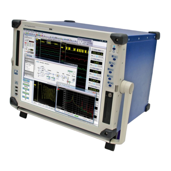
Page 77: Perception Software
Dedicated hardware support allows for live and accurate display of real-time ® data. HBM’s StatStream display technology enables even high resolution files to be viewed instantly regardless of acquisition size or network speed. I2679-4.0 en... - Page 78 GEN5i In addition the Perception software includes a variety of numerical displays and “VU-meters” with alarm levels that are configurable and scalable to suit various requirements and conditions. Perception provides the measurement functionality you need to work with ease and efficiency. The cursor measurements with horizontal, vertical and slope cursors with a swiftly updated result table allows for fast and easy access to points of interest.
- Page 79 GEN5i Advanced reporting: a DTP-alike tool for the creation of stunning reports with displays, tables, results, etc. Information: a tool to include a variety of information in your experiment. Other specialized options are available as a cost option and include Custom Software Interface programming CSI, STL formulas, BE256 / Multipro control, BE3200 Test Sequencer control, and HPHV Automated Analysis.
-
Page 80: Perception Language Setting
GEN5i 6.11 Perception language setting Various program settings are stored in the Perception Preferences. These settings include, but are not limited to, Perception language, start-up options, options for updates, video information, display settings, etc. Figure 6.10: Preferences dialog To open the Preferences dialog: Click Preferences... - Page 81 GEN5i User Interface Language options To startup Perception in a specific User Interface Language: Click Preferences... in the File menu. Select General in the tree view of the Preferences dialog. In the Language drop down list box you have the following choices: Figure 6.11: User Interface Language area (detail) default: The software detects the operating system language and uses that language (if available).
- Page 82 GEN5i B Perception Standard The standard Perception GUI. This is default on PCs and the GEN5i. C Instrument Panel The Instrument Panel GUI which is default for a GEN2i and GEN3i. Perception will start in the defined User Interface mode. I2679-4.0 en...
-
Page 83: Set Up Your Gen5I
GEN5i 7 Set up your GEN5i PC connections GEN5i has a PC motherboard inside. This PC motherboard has a lot of connections that can be used to connect other devices to the GEN5i system. Figure 7.1: PC connections (rear) PS/2 Mouse and keyboard Display connector USB connectors Audio connectors... - Page 84 GEN5i Audio connectors The onboard motherboard audio circuit implements 7.1+2 Channel High Definition Audio with UAA (Universal Audio Architec- ture). The GEN5i unit is shipped with an internal speaker (mono) only. Through the Microsoft Windows 7 operating system audio settings can be changed for 2, 4, 6 or 8 channel configuration.
-
Page 85: Pc Plug-In Cards
GEN5i PC plug-in cards The motherboard in GEN5i has 3 extension slots for plug-in cards available to the user. These slots are one 4-Lane PCI-Express 4x (in 16x connector) and two PCI (slot 1 and slot 2). Max. card length for all slots is ½ length (max. 174 mm). -
Page 86: Installing Plug-In Cards
GEN5i CAUTION HBM uses state-of-the-art electronic components in its equipment. These electronic components can be damaged by discharge of static electricity (ESD). ESD damage is quite easy to induce, often hard to detect, and always costly. Therefore we must emphasize on the importance of ESD preventions when handling a GEN5i system, its connections or a plug-in card. - Page 87 GEN5i Remove the screw holding the card retention bracket. Figure 7.4: GEN5i extension slots (top view) Retension bracket/Release screw PCI slot 1 PCI slot 2 PCIe x4 Hook-in retension bracket Lift the card retention bracket and put it aside in a secure place. If installing a new card, remove the corresponding filler bracket to create a cardslot opening.
- Page 88 GEN5i 12 Place top cover back in position. 13 Fasten all screws for the top cover (12x Phillips 1, 2x hex 2.5 mm and 2x Torx 20). 14 Connect any cables that should be attached to the card. See documentation for the card for information about the card’s cable connections.
-
Page 89: Removing And Installing Acquisiton Modules
GEN5i Removing and installing acquisiton modules CAUTION HBM uses state-of-the-art electronic components in its equipment. These electronic components can be damaged by discharge of static electricity (ESD). ESD damage is quite easy to induce, often hard to detect, and always costly. Therefore we must emphasize on the importance of ESD preventions when handling a GEN5i system, its connections or a plug-in card. -
Page 90: Installing Modules
GEN5i Loosen the small set screw on both ejectors on the module. Figure 7.5: Removing modules (Part 1) Press the inner grey button on each ejector to release the catch. Figure 7.6: Removing modules (Part 2) Press both ejectors outward to release the module. They act as levers to gently pull the module from its backplane sockets. - Page 91 GEN5i Press both ejectors inward to seat the module. They act as levers to gently pull the module into its backplane sockets. The gray button should snap to its default position and lock the ejectors. Tighten the small set screw on both ejectors on the of the card/module: Figure 7.7: Card/module ejectors with screws WARNING Screws must be locked to meet CE emissions.
-
Page 92: Protective Cover
GEN5i Protective cover The GEN5i is shipped with a protective cover protecting the sensitive LCD display from damage during transport or storage. Beside it protects the display it also can store the keyboard and mouse in the accessories box. Keyboard and mouse are shipped in an enclosed separate box during shipment from manufacturer to customer. -
Page 93: Opening Accessories Box
GEN5i Open the cover latches on both sides as shown on protective cover instructions. Figure 7.9: Open protective cover latches Remove the protective cover. 7.4.2 Opening accessories box To open accessories box: Put protective cover over flat surface with outside face up. Take protective cover left and right side and gently pull these sides outwards. -
Page 94: Closing Accessories Box
GEN5i 7.4.3 Closing accessories box To close accessories box: Put the accessories box on flat surface and put keyboard and mouse inside. Figure 7.11: Accessories box with mouse and keyboard in it Hold protective cover over the accessories box. Pick up the total and gently push accessories box inside the protective cover. -
Page 95: Handle
GEN5i Handle The handle is used to carry the GEN5i system. Only carry the instrument when the handle is in the mid-position. Figure 7.12: GEN5i with handle in the mid-position The handle can be turned to the top- or bottom side. When the handle is turned to the bottom side it can be used to slightly lift the instrument front so the display angle is towards the user. - Page 96 GEN5i Figure 7.13: Handle push buttons 3 Gently lift the instrument front and turn the handle down parallel to the front. 4 Release the handle push buttons and the handle will snap in fixed position. 5 Now GEN5i can stand on its handle. Figure 7.14: GEN5i stands on handle To turn handle: 1 Put instrument on flat surface.
- Page 97 GEN5i Figure 7.15: Handle push buttons 3 Turn the handle in position. 4 Release the handle push-in buttons and the handle will snap in one of its fixed positions (30° indexing). Figure 7.16: GEN5i multiple handle positions I2679-4.0 en...
-
Page 98: Feet
GEN5i Feet GEN5i is standing in normal operation position on 4 feet. Two positioned at the rear and two at the front of the instrument. The front feet can be used to lift the instrument front so the display angle is towards the user. The angle between display and vertical is about +12°... -
Page 99: Turning Feet In
GEN5i 7.6.2 Turning feet in To turn feet in Put instrument on flat surface. Slightly lift the instrument front. Push in the front feet by turning the feet towards the back. Gently put down GEN5i front. Figure 7.18: GEN5i stand on feet in I2679-4.0 en... -
Page 100: Getting Started
GEN5i 8 Getting Started Front panel control Standby On the GEN5i the power button is located on the front panel. When this button is pressed, the instrument state toggles between operating and standby mode. In standby mode some power will be consumed and the instrument is NOT disconnected from the AC supply. - Page 101 GEN5i Figure 8.1: Front panel control Power standby Start Stop Single Shot Pause Trigger A Power standby B Start The Start command starts acquisition of data. C Stop To stop or abort an acquisition press this button. The active data storage will be finished.
- Page 102 GEN5i E Pause This button serves two purposes: When no acquisition is active it will place the system in the pause or stand-by mode. Although the system is digitizing, no data is stored in memory or on disk. This is useful for monitoring purposes. When a continuous or sweeped acquisition is active, it will place the system in a hold mode: although the unit is digitizing, no data is stored in memory or on disk.
- Page 103 GEN5i CD/DVD device Figure 8.3: GEN5i CD/DVD reader/writer DVD slot Eject button The GEN5i has a DVD writer built in. It supports most of the available CD and DVD formats (read and write) and sizes (4.7 GB and 8.5 GB). The DVD writer can be used to install new software and/or back up your valuable data.
- Page 104 GEN5i To eject the disk press the eject button, please see callout (B) in Figure 8.3. I2679-4.0 en...
-
Page 105: Getting Started
GEN5i Getting started When GEN5i is started up for the first time, the Perception software will start and automatically connect to the integrated GEN5i data acquisition unit. Perception starts in the continuous mode and the acquisition unit will go into Pause mode: incoming signals will be monitored, but no data is stored. -
Page 106: Network Interfacing
GEN5i Network interfacing The GEN5i contains three network interfaces: two wired and one wireless. One of the wired network interfaces is used internally for the communication between the PC and the acquisition system. The other network interface can be used to connect the GEN5i integrated PC to a local network or the Internet. Click Start Select Control Panel Open Network Connections... - Page 107 GEN5i Figure 8.5: Internet Protocol property sheet You can access these settings as follows: In the Network Connections dialog right-click the icon of the network. On the context menu click Properties. In the Properties dialog click the Internet Protocol Version 4. Click Properties.
-
Page 108: Wireless Network
This disables the use a wireless network premanently. Before ordering contact HBM sales and after delivery contact HBM service to remove or electronic disable the WIFI. The adapter features full compliance with the IEEE 802.11 b/g/n wireless standard offering the best compatibility and future-proof reliability. - Page 109 GEN5i ● The network is listed To connect to a network that is listed in the Connect to a network dialog box, double-click the network name or click the network name and then click Connect. If the connection attempt is not successful, use Windows Network Diagnostics to diagnose the problem and suggest a solution.
-
Page 110: Acquisition And Storage
GEN5i 9 Acquisition and Storage Introduction Data acquisition hardware within the GEN5i is based on the concept of a recorder. A recorder consists of a number of acquisition channels that share the same basic recording parameters sample rate, sweep length and pre- and post-trigger length. -
Page 111: Acquisition
GEN5i Acquisition Since many of the features that are described here are controlled from within the Perception software, it is advised to read this section in combination with the corresponding sections in the Perception manual. The GEN5i/Perception combination provides the following acquisition controls: ●... -
Page 112: Storage
GEN5i Storage The GEN5i provides two storage paths as shown in Figure 9.1 on page 110: Store data in on-board RAM at high speed Transfer data directly at reduced speed to the controlling PC or (when installed) to a local hard disk. In addition to these storage paths the GEN5i provides two fundamental storage modes: Sweeps: data storage of predefined length. -
Page 113: More On Sweeps
GEN5i Figure 9.3: Acquisition: Run - Storage: Sweeps only The basic storage modes can be combined to create more advanced storage modes: Dual In this mode, sweeps as well as continuous data is stored. Therefore the end result is a recording that comprises the higher speed sweeps as well as the lower speed continuous data in between the sweeps. -
Page 114: Pre-Trigger Sweeps
GEN5i Figure 9.4: Ring buffer operation of memory The physical memory therefore forms a ring buffer, into which information can be continuously added (Figure 9.4). This process of filling the ring buffer memory terminates only when the recording logic indicates that the recording must be ended. - Page 115 GEN5i Figure 9.5: Ring buffer with trigger and end-of-recording Since the trigger stops the storage, all stored information is termed pre-trigger information. When storage stops because the acquired signal has met a trigger condition, only pre-trigger information is available - information recorded before the signal met the trigger condition.
-
Page 116: More On Continuous Data Storage
GEN5i The usage of a variable delay counter allows for a user-definable pre-trigger length. The length of the pre-trigger segment equals the length of the memory segment minus the delay. When the length of the delay is equal to, or exceeds, the length of the memory segment, only post-trigger information is available. - Page 117 GEN5i Circular The continuous mode is circular when storage is started and stopped manually AND the length of the buffer is defined. Operation is now equal to standard sweep storage, but on PC hard disk and not in volatile memory. In this mode the lead-out is specified which is basically the same as the post-trigger segment in a sweep recording.
-
Page 118: Time Base
GEN5i Time base The power of modern data acquisition techniques is achieved by digitizing analog information. Digitizing is the conversion of the instantaneous value of an analog signal (static or dynamic) into a numeric value. When the signal varies, sampling the instantaneous amplitude at sufficiently rapid intervals converts this signal into a series of numbers that can represent the original analog signal. -
Page 119: Time Base Settings For Fft's
GEN5i The above selection is made in the Perception software in the Settings Sheet ► Mainframe ► Internal Clock Base and is therefore mainframe-wide, i.e. the same for all recorders. A binary clock base is a useful time base settings when doing FFT’s (frequency domain analysis). -
Page 120: Additional Information
GEN5i Table 9.1: Examples of FFT Bin sizes TIME BASE FFT SIZE (SWEEP LENGTHS) MAIN = 1.024 1024 2048 4096 8192 SMP/S DIVI- FFT BIN SIZE IN HZ 1024000 1 4000 2000 1000 512000 2 2000 1000 62.5 256000 4 1000 62.5 31.25... - Page 121 GEN5i As an example assume a sweep of 8192 points (N=8192) and a sample rate of 40.96 kHz. This will yield the following: Frequency resolution Δf = (½ * 40960) / (½ * 8192) = 5 Hz Number of frequency domain points: N/2 = 4096 The minimum frequency component that can be measured is equal to the frequency resolution Δf = 5 Hz The maximum frequency component that can be measured is 40.96 kHz /...
-
Page 122: 10 Digital Trigger Modes
GEN5i 10 Digital Trigger Modes 10.1 Introduction Within the GEN5i data acquisition system, each and every channel is equipped with a trigger detector, which makes it possible to record just the phenomenon of interest, instead of having to search the full memory to find it. The trigger detector gives the system the power to capture elusive, short and unpredictable events. -
Page 123: Understanding Digital Triggering
GEN5i 10.2 Understanding digital triggering Technically speaking, there are two approaches to determine the known, pre- defined situation of the signal: analog or digital. Each channel in the GEN series system is equipped with a digital trigger detector, because it has stable vertical reference levels, because it does not encounter horizontal jitter, and because it is frequency independent. - Page 124 GEN5i As explained later in this chapter, a signal must actually cross the preset level. This is to avoid erroneous triggering on a small amount of noise on the signal. To make the trigger detector even more stable when noisy signals are used, the single-level trigger detector has been expanded with a hysteresis.
-
Page 125: Valid Trigger Conditions
GEN5i 10.2.2 Valid trigger conditions Trigger detection is based on level crossing: A signal has to cross a specified level to be considered a trigger condition. As a consequence, reaching the required level is not a valid trigger condition. Since trigger detection is digital, inter-sample analog values are omitted. - Page 126 GEN5i Figure 10.2 shows the influence of the additional hysteresis. Fundamentally all is the same as described earlier. The only difference now is that a second level (H) is used to 'arm' the level trigger detector. Otherwise stated, the trigger level has been expanded to be a trigger zone that spans multiple levels.
-
Page 127: Trigger Modes
GEN5i 10.3 Trigger modes Using the various trigger modes, your GEN5i data acquisition system is expanded to an extremely versatile transient recorder. The trigger circuits may be configured to trigger on many types of phenomena. In this section the different trigger modes and their extensions are discussed in detail. 10.3.1 Basic trigger mode The basic trigger mode can be compared with the trigger mode available when... -
Page 128: Dual Trigger Mode
GEN5i 10.3.2 Dual trigger mode In dual trigger mode two detectors are active and working in parallel: the primary level P and the secondary level S. With two levels it is possible to define a range the input signal must be within. As soon as the signal becomes larger than the upper level, or smaller than the lower level, the detector will generate a trigger. -
Page 129: Window Trigger Mode
GEN5i 10.3.3 Window trigger mode For the window trigger mode both levels are used. One of them has a dual function: arm and trigger, the other is used as a disarm level. To generate a trigger, the trigger detector must be armed. This is done by crossing the arm/ trigger level in the opposite direction. -
Page 130: Dual-Window Trigger Mode
GEN5i 10.3.4 Dual-window trigger mode The dual-window trigger mode is a more sophisticated version of the window trigger mode. Now both levels are used as an arm/trigger/disarm level. This allows the trigger detector to react on a dip in both directions. Figure 10.6: Dual-window trigger mode Trigger Diagram A shows one situation, diagram B the other situation with the same... -
Page 131: Sequential Trigger Mode
GEN5i 10.3.5 Sequential trigger mode The two level comparators are set in a sequence in this mode. One is used to arm the trigger detector while the other is used to actually generate the trigger: if the incoming signal crosses the level of the first comparator, the second is activated (armed). -
Page 132: Trigger Qualifier
GEN5i 10.3.6 Trigger qualifier The trigger detectors of a channel can also be used as a qualifier. A trigger qualifier is a situation that enables (arms) the recorder trigger features. The recorder trigger features are a combination of various channel, external, between-recorders and other trigger options. -
Page 133: Trigger Add-Ons
GEN5i 10.4 Trigger add-ons The mentioned trigger modes can be combined with a variety of extra features, allowing to trigger on almost any signal. Some of these extras are used to fine-tune the selected trigger mode, other features expand the capabilities of the basic trigger detector. The following simplified diagram is from the settings sheet and shows the building blocks that make the complete channel trigger logic. -
Page 134: Pulse Detector
GEN5i Figure 10.9: Slope trigger Trigger Original signal Differentiated signal With the slope triggering it is possible to trigger on a specific change in slope of the signal, for example on a spike on a repetitive signal: if the slope (or frequency) of the signal exceeds the specified level, a trigger will be generated. -
Page 135: Holdoff
GEN5i Figure 10.10: Pulse detector Trigger Width Figure 10.10: In diagrams A and B the pulse detection is depicted. In diagram A, when the trigger level is crossed, the signal remains above the trigger level for a time interval larger than pulse width W. In diagram B there is a situation in which the signal returns through the trigger level within pulse width W. -
Page 136: Interval Timer
GEN5i Figure 10.11: Trigger holdoff Trigger Holdoff The feature is most useful in combination with the interval timer and/or the event counter. 10.4.4 Interval timer A highly sophisticated trigger add-on is the interval timer. The interval timer is used to define a time relation between two trigger events. When the time relation is correct, a trigger is generated. -
Page 137: Interval Timer - More
GEN5i Figure 10.12: Interval timer - Less Trigger Interval The time interval is reset on the first new trigger event. This feature allows you to detect additional pulses in a standard train of pulses for example. Interval timer - More This interval timer mode is more complicated. -
Page 138: Interval Timer - Between
GEN5i This function allows you to detect a “missing” pulse in a standard pulse train for example. Interval timer - Between For the Between mode basically two timers are used: one to set the start of a time window and a second to set the width of the time window. The second trigger event must be within this time window. -
Page 139: Interval Timer - Notbetween
GEN5i The first interval timer can be compared to the trigger holdoff feature described earlier. The second interval timer defines a period in which a trigger event must occur. If not, it is not a related trigger event. Interval timer - NotBetween The inverse function of the Between mode of the interval timer is the NotBetween mode. -
Page 140: Event Counter
GEN5i 10.4.5 Event counter Sometimes it is not possible to trigger on a specified condition using a selected trigger mode alone, because several events meet the required situation. So far we have seen “filters” that can be used to narrow the range of trigger candidates, like holdoff and interval timer. -
Page 141: Recorder And System Trigger
GEN5i 10.5 Recorder and system trigger The trigger modes and features described so far are channel-based. Each analog channel within a GEN series system has a digital trigger detector. The trigger signals of all channels of a single recorder are combined through a logical OR to generate a combined trigger. - Page 142 GEN5i Internal Trigger Line 1 through 3: There are three internal trigger lines. These are used to transfer recorder triggers from one recorder to another. Each recorder can select to set its recorder trigger on one or more lines. It can also pick up a trigger from one or more lines.
-
Page 143: Channel Alarm
GEN5i 10.6 Channel alarm Each channel has the capability to generate an alarm. An alarm situation is detected with a basic dual level detector. There are two alarm modes: Basic single-level alarm. For details see "Basic trigger mode" on page 127. Dual-level alarm. -
Page 144: 11 Interface/Controller Module
In both cases please provide us with the serial number of your mainframe. You will find this number at the label on the rear side of the mainframe. -
Page 145: Interface/Controller Module 2 (Im2)
GEN5i 11.2 Interface/Controller Module 2 (IM2) Figure 11.2: Interface/Controller module IM2 Standard 1 Gbit Ethernet Interface Optical 1 Gbit Ethernet Interface Master/Slave Synchronisation External Trigger Out External Trigger In External Event Out G External Time base In Recessed Mainframe Reset Switch The CPU Reset Switch can be used to reset the controller/interface in the rare event of a system malfunction. -
Page 146: Im2 - Communication And Control
GEN5i The IM2 has a unique Communication section with 1 Standard Ethernet Interface, 1 Optical Ethernet Interface with 2 activity LEDs and a Master Slave Interface with 2 activity LEDs. The 4 I/O connectors are very similar to the IM1 connectors however the reset switch on the IM2 is above the first connector on this module. -
Page 147: Using The 1 Gbit Option Connections
GEN5i Using the 1 Gbit Option Connections LC Connection Using the SFP + Option LC optical connections that need an SFP device to enable their use with LC connected optical cable. Master Slave Synchronization = Link up/ = Receiver enable active(green) (green) On;... -
Page 148: Im2 - I/O Connectors
GEN5i Extended Synchronization: Standard synchronization and Start/Stop and Pause of a recording across multiple mainframes each controlled by a separate Perception. Stop recording is a non synchronous action. Synchronous manual trigger, user software action to trigger all mainframes synchronously. IM2 - I/O connectors 11.2.3 Figure 11.3: Interface/Controller Module IM1 - (BNC connectors) External Time base In - (EXT CLK IN) -
Page 149: Im2 - Expansion Slot
GEN5i IM2 - Expansion slot 11.2.4 Figure 11.4: Expansion slot on Interface/Controller Module IM2 Free space for option Note For more details see “Interface/Controller Module options” on page 144. I2679-4.0 en... -
Page 150: Im2 - Iscsi Based Storage
GEN5i IM2 - iSCSI based storage 11.3 What is iSCSI? iSCSI; Internet SCSI (Small Computer System Interface). SCSI is an older standard used by storage devices to communicate with PC’s to exchange the data. Specifically, iSCSI is a TCP/IP based communication protocol. -
Page 151: Introduction: Iscsi Nas With Gen Daq Network
GEN5i 11.3.1 Introduction: iSCSI NAS with GEN DAQ network By supporting the iSCSI protocol the GEN DAQ systems can directly store the recorded data on a storage device attached to your network. The basic setup will look like this: Figure 11.5: iSCSI setup with local NAS In Figure 11.5 a networked PC is attached to a GEN DAQ system to control and setup the GEN DAQ system connections. -
Page 152: Tcp/Ip Connection With An Nas
GEN5i 11.3.2 TCP/IP connection with an NAS To enable the GEN DAQ system to communicate with the storage device, several layers of communication need to be established. There are several ways to make these connections with different setups. When using a dedicated network as shown in Figure 11.5 with no other systems attached, a fixed IP address must be setup on your NAS. -
Page 153: External Storage Setup Dialog - Perception
GEN5i External Storage Setup dialog - Perception 11.3.3 To setup a NAS device in software Perception, first connect to the GEN DAQ system used for iSCSI storage, open Perception and navigate to the Settings menu and click External Storage Setup. Figure 11.6: External Storage Setup dialog GEN Data acquisition system iSCSI Host... -
Page 154: Iscsi Host
GEN5i Note Do not select the same Network Interface for both iSCSI 1 and iSCSI 2. 11.3.5 (See Figure 11.6 - B) iSCSI Host These settings are input manually and are used to locate your NAS on your network. There are two ways to find your NAS server, listed below. Select either DNS name or IP address. -
Page 155: Target Name (Iqn)
GEN5i Simplified, the NAS server looks like this: Figure 11.7: NAS server - Overview 11.3.7 (See Figure 11.6 - C1) Target Name (IQN) The target name is used in the selection process to identify the correct iSCSI LUN setup inside your NAS server. The Target Name must match the IQN Name setup in your NAS server software. -
Page 156: How To Format The Iscsi
GEN5i Password: The same password that was defined during the NAS setup process, for reference see Figure J.7 "Create a new iSCSI target dialog" on page 580. Refresh/Format the iSCSI Figure 11.8: External Storage Setup - Refresh/Format option Status message Refresh Format Click Refresh (B) to force the status message to read the most current real... -
Page 157: 11.3.10 Status Messages/ Troubleshooting
GEN5i To format the iSCSI for the first time click Format. Figure 11.9: iSCSI Format option - Warning dialog A Warning dialog (Figure 11.9) will appear asking if you’d like to format, click OK to start the procedure or Cancel to quit. Once formatted the iSCSI should be ready to use by Perception. - Page 158 GEN5i Status Meaning Check solution No iSCSI host found Connection to NAS TCP/IP host was not configured as iSCSI succeeded, Can’t find server an iSCSI on host port NAS uses a different iSCSI Port number Unknown target iSCSI protocol Check the iSCSI target connection made but name iSCSI target name not...
-
Page 159: 11.3.11 Setup An Iscsi Nas Connected Across An Ethernet Switch
GEN5i 11.3.11 Setup an iSCSI NAS connected across an Ethernet switch This is the simplest setup of a GEN DAQ system with the NAS connected through an Ethernet switch on the same network as the control PC and GEN DAQ system. This setup can be used in situations where the individual components of the system are all connected to the same network via an Ethernet switch, this allows freedom of placement of each component in the system. - Page 160 GEN5i After the GEN DAQ is configured the NAS should be configured. To configure ® the NAS, use the manufacturers guides. An example of further Synology ® configuration is given in the appendix “Setting up the iSCSI with Synology ® NAS”...
- Page 161 GEN5i GEN Data acquisition system - Network (See Figure 11.11 - A) interface: Select the Standard 1 Gbit Ethernet port that is connected to the Ethernet switch. Figure 11.12: Network interface connections/Standard 1 Gbit option (See Figure 11.11 - B) iSCSI Host DNS Name/IP Address: A DNS setting is not used in this setup.
- Page 162 GEN5i User name: Enter the details used during the setup procedure of the CHAP authentication on the NAS. If none were chosen, leave these field blank. Password: Enter the details used during the setup procedure of the CHAP authentication on the NAS. If none were chosen, leave these field blank.
-
Page 163: 11.3.12 Setup An Iscsi Nas Connected Without An Ethernet Switch
GEN5i 11.3.12 Setup an iSCSI NAS connected without an Ethernet switch This is basic setup of a GEN DAQ system with a NAS connected directly at the GEN DAQ system. A Ethernet switch is not required. All components are locally based and can be connected to one host PC. - Page 164 GEN5i Connect Equipment (See Figure 11.14) Connect the PC via an Optical Ethernet connection to the optical Ethernet connector of the GEN DAQ system. Connect the NAS to the GEN DAQ system via the Standard RJ45 connection or if the option is installed use a second optical Ethernet connection.
- Page 165 GEN5i The External Storage Setup dialog: The information in this dialog must match the information defined in the configuration of the connected NAS. Refer to the appendix “Setting up the ® iSCSI with Synology NAS” on page 574 when necessary for an example ®...
- Page 166 GEN5i If you have connected the NAS server to the Optical network connector of the GEN series mainframe then select the Optical 1 Gbit Ethernet. Figure 11.17: Network interface connections/Optical 1 Gbit option (See Figure 11.11 - B) iSCSI Host DNS name/IP address A DNS setting is not used in this setup.
-
Page 167: 11.3.13 Setup An Iscsi Nas Connected To A Corporate Network - Basic Setup
GEN5i Password: Enter the details used during the setup procedure of the CHAP authentication on the NAS. If none were chosen, leave these field blank. Click Apply when done to set the new settings and then click Close. The NAS should now be available in the setup of your GEN series mainframe. Figure 11.18: Storage location with options 11.3.13 Setup an iSCSI NAS connected to a corporate network –... - Page 168 GEN5i Figure 11.19: GEN DAQ with iSCSI NAS connected across an Ethernet switch and connected to a corporate network Connect Equipment: The Ethernet switch should be connected to the Company network. Connect the PC via a standard RJ45 Ethernet connection to the Ethernet switch.
- Page 169 GEN5i Setup in Perception: Start Perception and navigate to the Settings menu and select External Storage Setup. Please make sure you have read section Explaining the External Storage Setup Dialog (see Figure 11.20) before executing this procedure. The External Storage Setup dialog: The information in this dialog must match the information defined in the configuration of the connected NAS.
- Page 170 GEN5i Select the Standard 1 Gbit Ethernet port that is connected to the Ethernet switch. Figure 11.21: Network interface connections/Standard 1 Gbit option (See Figure 11.20 - B) iSCSI Host DNS Name/IP Address As the setup is part of a corporate network, a DNS setting should be used in this setup.
- Page 171 GEN5i Password: Enter the details used during the setup procedure of the CHAP authentication on the NAS. If none were chosen, leave these field blank. Click Apply when done to set the new settings and then click Close. The NAS should now be available in the setup of your GEN series mainframe. Figure 11.22: Storage location with options I2679-4.0 en...
-
Page 172: 11.3.14 Setup An Iscsi Nas Connected To A Corporate Network - Advanced Setup
GEN5i 11.3.14 Setup an iSCSI NAS connected to a corporate network – advanced setup This setup of a GEN DAQ system with the NAS connected through an Ethernet switch on a corporate network. Compared to the example 3 ("Setup an iSCSI NAS connected without an Ethernet switch"... - Page 173 GEN5i Connect equipment (See Figure 11.23) Connect the PC via standard RJ45 Ethernet connection to the Ethernet switch. Connect the GEN DAQ system by using both the standard RJ45 Ethernet and the 1 Gbit optical Ethernet interface to the Ethernet switch.
- Page 174 GEN5i Please make sure you have read section Explaining the External Storage Setup Dialog (see Figure 11.24) before executing this procedure. The External Storage Setup dialog: The information in this dialog must match the information defined in the configuration of the connected NAS. Refer to appendix “Setting up the ®...
- Page 175 GEN5i GEN DAQ - Network interface: (See Figure 11.24 - A) If you have connected the NAS server to the RJ45 connector of the GEN series mainframe then select the Standard 1Gbit Ethernet. Figure 11.25: Network interface connections/Standard 1 Gbit option If you have connected the NAS server to the Optical network connector of the GEN series mainframe then select the Optical 1Gbit Ethernet.
- Page 176 GEN5i Use CHAP: Select Use CHAP if CHAP password protection was selected during ® the setup of your NAS server. When using a Synology NAS, CHAP password protection can be selected. (For more information, please refer to Figure J.7 "Create a new iSCSI target dialog"...
-
Page 177: Im1 - Interface/Controller Module
GEN5i IM1 - Interface/Controller Module 1 11.4 Figure 11.28: Interface/Controller Module IM1 Recessed CPU Reset Switch Activity detected Standard 1 Gbit Ethernet Interface Link detected External Trigger Out External Trigger In G External Event Out External Time base In I2679-4.0 en... -
Page 178: Im1 - Communication And Control - Standard Ethernet Interface
GEN5i The CPU Reset Switch can be used to reset the controller/interface in the rare event of a system malfunction. To reset the unit carefully press the recessed switch with a small screwdriver or equivalent. The IM1 has a unique Communication section with 1 Standard Ethernet Interface and 4 activity LED's. -
Page 179: Im1 - Expansion Slot
GEN5i External Event Out (EV OUT) C, D External Trigger In/Out (TRG IN/TRG OUT) The controller/interface provides 4 BNC connectors with the following functions: External Time base In (TB-A IN) This input can be used to provide another time base for the ADC rather than the internal one. -
Page 180: Im2 - Interface/Controller Module Options
GEN5i IM2 - Interface/Controller Module options 11.5 Your GEN5i data acquisition system can be equipped with a variety of options. Most options are factory-installed, i.e. you must choose an option at the time of ordering or return the instrument to a qualified service point for upgrade. The IM2 Interface/Controller modules of the GEN series mainframe have one expansion slot that can be used for one of the following options: Option (for IM2) -
Page 181: Option - Optical 1 Gbit Ethernet Interface
GEN5i For specifications and ordering information see "B3723-1.0 en (GEN series GEN5i Portable Data Recorder)" on page 312. Option - Optical 1 Gbit Ethernet interface 11.5.2 The Interface/Controller Module IM2 supports an optical 1 Gbit Ethernet interface by means of a user installed SFP module. An SFP module is a small form-factor pluggable transceiver that supports direct optical network connections. -
Page 182: Cable Selection And Lengths
GEN5i Note 1310 nm Single Mode (SM) and 850 nm Multimode (MM) optical fiber transceivers use specific cables and connectors therefore please check the correct mode/specification of fiber optic cable is used. Cable selection and lengths: Cables require different properties when they exceed certain lengths based on the properties of light in an optical fiber. -
Page 183: Connections And Using The 10 Gbit Option
GEN5i Figure 11.32: 10 Gbit Ethernet card - with SFP+ module - card. Throughput speed is Note The maximum 10 Gbit throughput speed is per therefore a shared specification for both interfaces combined. It is possible that two interfaces can be used at the same time but only when one interface is used for communication and the other is used for storage. -
Page 184: Front Panel Layout
GEN5i Front panel layout The front panel of the 10 Gbit Ethernet option has the following layout: Figure 11.33: Front panel of XMC401 10 Gbit Ethernet Card CH B = NIC2 (Requires SFP+ module, not shown) ACT (green): Ethernet Activity (on when active) LNK (green): Ethernet Link (on when active) 10 Gbit (green): Ethernet Speed 10 Gigabit (always on) 1 Gbit (green): Ethernet Speed 1 Gigabit (always on) -
Page 185: Cable Selection And Lengths
GEN5i The two types of 10 Gbit SFP+ module that are used with this Ethernet card are: 10 Gbit (850 nm) - Multi mode 10 Gbit (1310 nm) - Single mode Note SFP modules rated at 1 Gbit and are not suitable for this card. Please select the SFP+ modules which are rated at 10 Gbit. -
Page 186: 10 Gbit Ethernet Card In Gendaq Series Networks
GEN5i Multi mode Cable is a type of cable that has a relatively thicker light carrying core. Light in a thicker core makes more reflections and is therefore only suited to shorter distances. The following table shows what mode of fiber is required for each distance covered. -
Page 187: Network Interface Selection In Perception
GEN5i Figure 11.36: Connect the 10 Gbit Ethernet Option to a PC 10 Gbit Ethernet card SFP+ modules A 10 Gbit PC network card without SFP+ modules inserted and Ethernet switch with an SC optical connection can be used to communicate with the 10 Gbit Ethernet card. -
Page 188: Important Note Windows® 7 - Optimum Settings
GEN5i Figure 11.37: Mainframe Network Setup Optical 10 Gbit NIC1 Optical 10 Gbit NIC2 Make this the preferred network for connection with Perception In Mainframe Network Setup you can define the IP address of each individual interface if needed. If Perception finds more than one interface for Network Selection as shown in Figure 11.37, then the interface that has a Check in the box Make this the preferred network connection with Perception will be the interface used for communication with Perception. -
Page 189: Installation Of 1 Gbit Sfp/10 Gbit Sfp+ Module
GEN5i ® Windows 7 10G network adapter settings: Interrupt moderation rate: high Receive side scaling ques: 8 Receive buffers: 2048 For more information on how to do this please see appendix “Optimal Windows settings for 10Gbit Ethernet Card” on page 566. Note The above Windows settings were tested and chosen using a specific setup of ®... - Page 190 GEN5i CAUTION HBM uses state-of-the-art electronic components in its equipment. These electronic components can be damaged by discharge of static electricity (ESD). ESD damage is quite easy to induce, often hard to detect, and always costly. Therefore we must emphasize on the importance of ESD preventions when handling a GEN5i system, its connections or a plug-in card.
-
Page 191: Installation Steps
GEN5i Installation steps First make sure the mainframe unit is switched off then locate the available SFP slot and remove the plastic plug (if inserted). Figure 11.38: Interface/Controller Module SFP location Interface/Controller Module SFP/SFP+ locations B,C Interface/Controller Module SFP+ location Remove cap* * In some cases you may have to remove a covering over the SFP slot. - Page 192 GEN5i Grasp module between fingers and thumb at the end with the small black removal-bar and Insert back end into the available SFP slot, until you hear a click. Figure 11.39: Insert device in IM2 Module Insert device Embedded software will recognize the device and connect to it automatically when the mainframe is powered on.
- Page 193 GEN5i To remove the module from the mainframe first make sure the mainframe is powered off and then grasp the small black removal-bar and pull away and out from the mainframe. The spring loaded removal-bar will release the SFP from the front panel. Figure 11.41: IM2 Module - Remove device G Remove device Then, if available replace the small plastic plug to protect the optical inlet.
-
Page 194: Optical Network (Sfp) - Trouble Shooting
GEN5i Optical Network (SFP) - Trouble shooting 11.5.5 If no connection is present on the fiber optic channel, first check the following: That the cable type matches the SFP module type (single-mode or multi-mode). For this you will need to check with the cable manufacturer specifications and the wavelength print on the label of the SFP module to compare - mode, 850 nm is multi - mode). -
Page 195: Removing Protective Cover On Gen2I And Gen5I
GEN5i 11.5.6 Removing protective cover on GEN2i and GEN5i Within the standard pack contents of this option are two protective covers for use with the GEN2i and the GEN5i. These covers are replacements for the older covers that are installed on the GEN2i and GEN5i. If using a GEN2i or GEN5i you can follow this replacement procedure. -
Page 196: Option - Irig And Irig/Gps Time Synchronization
GEN5i Removing SFP protective cover on a GEN5i To use the SFP option on a GEN5i with IM2 you need to remove the protective cover first. Note Requires screw driver Phillips #2. Figure 11.44: (GEN5i SFP cover - standard) When removed replace with the new cap to keep the socket protected. Figure 11.45: (GEN5i SFP cover - new) Option - IRIG and IRIG/GPS time synchronization 11.5.7... -
Page 197: Gps Antenna System Rules
GEN5i Figure 11.46: IRIG & IRIG/GPS board 11.5.8 GPS Antenna System Rules J1 GPS antenna connector (9-pin micro ‘DP’) J2 IRIG AM modulate Time Code In (SMB socket) J3 IRIG AM modulate Time Code Out (SMB socket) J4 IRIG DCLS time code In and Out (15-pin micro ‘DP’) SMB to BNC cable adapters included to allow standard coaxial cable connections to IRIG In and or Out SMB socket. -
Page 198: Rule 1. Antenna Placement
GEN5i Check www.symmetricom.com for option and detailed support on BC635PMC (IRIG) or BC637PMC (GPS) Rule 1. Antenna placement View of the sky Select an area where the GPS antenna will have an unobstructed view of the sky. An ideal position has no obstructions above 10 degrees above the horizon. -
Page 199: Rule 4: Interconnect Cables
GEN5i What do I need? A commonly used configuration is to place a lightning arrestor where the antenna cable enters the building (either inside or outside), because there is often a good earth ground nearby to connect to. If the cable between this lightning arrestor and the GPS receiver is longer than four meters, it is good practice to place a second lightning arrestor within four meters of the GPS receiver. -
Page 200: Im1 - Interface/Controller Module 1 Options
GEN5i IM1 - Interface/Controller Module 1 Options 11.6 Your GEN series data acquisition system can be equipped with a variety of options. Most options are factory-installed, i.e. you must choose an option at the time of ordering or return the instrument to a qualified service point for the upgrade. -
Page 201: Auto Detection
GEN5i The option provides an extra 1 Gigabit optical Ethernet link for the fastest possible communications. The use of fiber optic links in local area networks is now common place due to the inherent advantages of using fiber. High data rates can be maintained without electromagnetic or radio frequency interference (EMI/RFI). -
Page 202: Front-Panel Layout
GEN5i Front-Panel layout With the option installed the front-panel of the interface/controller module has the following layout: Figure 11.48: Front-Panel of the Interface/Controller Module ACT: Indicates channel activity LNK: Indicates Ethernet link status 100: Indicates link speed = 100 MB/s 1000: Indicates link speed = 1000 MB/s (1 GB/s) I2679-4.0 en... -
Page 203: Connection
GEN5i The following Figure 11.49 indicates the positioning of the transmit and receive plugs and orientation of the connectors and keying of the plugs. The SC-type socket is designed to support self-locking duplex SC-type male connectors. This ensures that the fiber optic plugs are securely fastened to the sockets. Figure 11.49: Receive (RX) - Transmit (TX) connector Keying Receive (RX) - Page 204 GEN5i To connect the fiber optic interface to a network, insert the SC connector on one end of the fiber optic cable into the interface, as shown in Figure 11.51. Ensure that the connector is inserted completely into the jack. Then insert the connector on the other end of the fiber optic cable into the connector on an Ethernet switch, or another computer system (as appropriate).
- Page 205 GEN5i Fiber Optic Ethernet Specifications Fiber optic Ethernet 1000 Base-SX full duplex, 1 GB/s Connectors SC-Type connectors for dual channel fiber optic data 1 Ch. in, 1 Ch. out RJ45 8 contact, female for dual channel standard copper communication Fiber optic Wavelength 850 nm Cable type Multimode Maximum cable length 500 m...
-
Page 206: Option - Scsi Interface Board
GEN5i Ordering Information Component Unit Description Order number Fiber optic Ethernet A replacement for the 1-G050-2 standard Ethernet connection, a combined fiber optical or copper Ethernet interface to a GEN7t or GEN16t mainframe. Option can only be installed at the factory. Option - SCSI interface board 11.6.2 The SCSI option provides expansion and flexibility, allowing GEN5i users to... - Page 207 GEN5i Figure 11.52: SCSI interface board SCSI Type Ultra320 SCSI 16-bit Connector Very High Density Cable Interconnect (VHDCI), 68-pin Speed To SCSI drive 8-10 MS/s (16-20 MB/s) To SCSI RAID drive 25-30 MS/s (50-60 MB/s) Max number of devices Cables Up to 12 m in length; 16 devices Cables Over 12 m in length;...
-
Page 208: Option - Irig And Irig/Gps Time Synchronization
GEN5i Ordering Information Article Description Order No. External Hard Disk Drive Needs interface option, stand 1-G005-2 alone Hard Disk Drive housing with 300 GB Hard Disk Drive; including connection cable to SCSI interface Rack Hard Disk Drive GEN series Rack mount 1-G006-2 300 GB SCSI Hard Disk Drive with housing;... -
Page 209: Gps Antenna System Rules
GEN5i 11.6.4 GPS Antenna System Rules J1 GPS antenna connector (9-pin micro ‘DP’) J2 IRIG AM modulate Time Code In (SMB socket) J3 IRIG AM modulate Time Code Out (SMB socket) J4 IRIG DCLS time code In and Out (15-pin micro ‘DP’) SMB to BNC cable adapters included to allow standard coaxial cable connections to IRIG In and or Out SMB socket. - Page 210 GEN5i Lightning considerations Locate the antenna at least 15 meters away from lightning rods, towers, or structures that attract lightning. GPS antenna damage is usually not the result of a direct lightning strike, but the effects of a lightning strike on a nearby structure.
- Page 211 GEN5i Rule 4: Interconnect cables Cable options Symmetricom’s interconnect cables are available in various lengths. For ease of pulling antenna system cable through a conduit, or if you wish to cut the cable to an exact length, you may choose to have a connector on only one end.
-
Page 212: Master/Slave Card
GEN5i 11.7 Master/Slave Card The GEN series can be operated as a fully synchronized Multi-Mainframe system with multiple mainframes using the Master/Slave card. With the Master/Slave card you can: connect one GEN series “Master” to up to eight “Slaves” fully synchronize up to nine mainframes record up to 1080 channels with 1 MS/s sampling speed each by using all slots or record up to 540 channels with 100 MS/s per channel by using all slots... -
Page 213: Master/Slave Card Operations
GEN5i In Slave mode: the top connector is configured as slave input, all other connectors are unused all received signals are transferred to a bus for internal distribution internal slave trigger signals are transferred to the outside In Stand-alone mode: Stand-alone mode is OFF: the Master/Slave card does not communicate with other Master/Slave cards. - Page 214 GEN5i Figure 11.53: Master/Slave card In Master mode, all connectors M function as master output (OUT 1 to OUT 8). In Slave mode, the top connector S functions as a slave input (IN), all other connectors are unused. ® Figure 11.54: Example of a duplex LC connector I2679-4.0 en...
-
Page 215: Led Indicators
GEN5i LED indicators On the front panel of the Master/Slave card two LEDs indicate the status of the link. icon is used to identify the signal detect function. icon is for data/synchronization identification. Figure 11.55: LED indicators icon icon The following table shows the function and possible combinations of the two LEDs. - Page 216 GEN5i In the GEN series tower model the Master/Slave card is installed on the left- hand side of the Interface/Controller module. Figure 11.56: GEN series tower model with Master/Slave card installed Master/Slave card Interface/Controller module I2679-4.0 en...
- Page 217 GEN5i In the GEN series 19” rack model the Master/Slave card is installed into Slot A on the right-hand side of the Interface/Controller module. Figure 11.57: GEN series 19” rack model with Master/Slave card installed Interface/Controller module Master/Slave card (Slot A) Note With a Master/Slave card installed the GEN series 19”...
-
Page 218: Installation
On the GEN series 19” rack model remove the acquisition card from slot A. CAUTION HBM uses state-of-the-art electronic components in its equipment. These electronic components can be damaged by a discharge of static electricity (ESD). Therefore, we must emphasize the importance of ESD preventions when removing or installing cards/modules. - Page 219 GEN5i The built-in laser complies with laser product standards set by government agencies for Class 1 laser products: In the USA, the Master/Slave card is certified as a Class 1 laser product conforming to the requirements contained in the Department of Health and Human Services (DHHS) regulation CDRH 21 CFR, Chapter I Subchapter J Part 1040.10.
- Page 220 GEN5i Slide the card into its guide rails until the ejectors contact the perforated metal strips at top and bottom. Figure 11.58: Slide in the card I2679-4.0 en...
- Page 221 GEN5i Press both ejectors inwards to seat the card. They act as levers to gently push the card into its backplane sockets. Figure 11.59: Press ejectors inwards I2679-4.0 en...
- Page 222 GEN5i Fasten the small set screw on both ejectors on the card. Figure 11.60: Ejector set screw The Master/Slave card is installed. Removing the Master/Slave card To remove the Master/Slave card: Shut down the GEN series and remove the power input cable. Loosen the small set screw on both ejectors on the card.
- Page 223 GEN5i Press the inner grey button on each ejector to release the catch. Figure 11.62: Inner gray button on ejector I2679-4.0 en...
- Page 224 GEN5i Press both ejectors outwards to release the card. They act as levers to gently pull the card from its backplane sockets. Figure 11.63: Press ejectors outwards I2679-4.0 en...
- Page 225 GEN5i Slide the card out of the GEN series unit. Figure 11.64: Remove the card I2679-4.0 en...
-
Page 226: Connecting The Master/Slave Card
GEN5i 11.7.3 Connecting the Master/Slave card With the fiber optic cable, connect the Master/Slave card labelled M, OUT of the master mainframe to the top connector labelled M/S IN of the Master/Slave card of the slave mainframes. Figure 11.65: Connecting the Master/Slave Master mainframe (M, OUT) Slave mainframe (M/S IN) Fiber optic cable... -
Page 227: Example Of A Master/Slave Configuration
GEN5i 11.7.4 Example of a Master/Slave configuration The following diagram shows an example of a Master/Slave configuration with a master driving four slave mainframes. Figure 11.66: Example of a Master/Slave configuration with four slave mainframes Master mainframe Slave mainframes Fiber optic cable Connect the Master/Slave card connector labelled M/S, OUT 1 of the master mainframe to the top connector labelled M/S IN of the Master/Slave card of the first slave mainframe. - Page 228 GEN5i Connect the Master/Slave card connector labelled M, OUT 3 of the master mainframe to the top connector labelled M/S IN of the Master/Slave card of the third slave mainframe. Connect the Master/Slave card connector labelled M, OUT 4 of the master mainframe to the top connector labelled M/S IN of the Master/Slave card of the fourth slave mainframe.
-
Page 229: Setting The Master/Slave Operating Modes
GEN5i 11.7.5 Setting the Master/Slave operating modes A Master/Slave card can be used as a master or slave. After installation of the Master/Slave card into the mainframe, set the operating modes in the Perception software. In the Perception work area: Figure 11.67: Perception work area with Master/Slave Settings tab General group... - Page 230 GEN5i To disable the Master/Slave operation and set the mainframe to Stand-alone mode: Select the mainframe that you want to use as a Stand-alone. Double-click on the Master/Slave mode cell to open it for modification. In the drop-down list that comes up, select Stand-alone. The Master/Slave operating mode of the mainframe has been set.
- Page 231 GEN5i If you have set the mainframe to Slave mode, the letter "S" appears in the GEN series front panel. Figure 11.69: Mainframe in Slave mode The installation of the Master/Slave option is completed. I2679-4.0 en...
-
Page 232: Setting The Master/Slave Trigger
GEN5i 11.7.6 Setting the Master/Slave trigger When the Master/Slave card is in use, a recorder can either put the recorder trigger on the Master/Slave trigger line and/or pick up the trigger from the Master/Slave trigger line. There are four settings that can be selected in the Perception software: Disabled No trigger transmitted to or received from other mainframes Transmit... - Page 233 GEN5i Figure 11.71: Perception work area with Master/Slave trigger Settings tab Trigger group Master/Slave trigger column To set the Master/Slave trigger in the Perception software, proceed as follows: If it is not already active, start Perception. Make sure that you are connected to the required mainframes. Use the Hardware Navigator to do this.
- Page 234 GEN5i In the drop-down list that comes up, select the setting you want to use. Figure 11.72: Master/Slave trigger list I2679-4.0 en...
-
Page 235: Setting The Synchronization Source (Sync Source)
GEN5i 11.7.7 Setting the synchronization source (Sync source) Depending on the selected synchronization source the date and time are controlled by either the PC (RTC), or an installed IRIG (IRIG) or IRIG/GPS (GPS) card. The source is selected in the Perception software. In the Perception work area: Figure 11.73: Perception work area synchronization source Settings tab... -
Page 236: Verification Procedure
GEN5i 11.7.8 Verification procedure To verify the correct operation of the Master/Slave configuration, proceed as follows: Hardware set-up Set-up two GEN series mainframes with each a Master/Slave card installed and with each at least one recorder card installed. Connect a TTL level, 1 Hertz signal to the top input of the first recorder card of the master mainframe and to the top input of the first recorder card of the slave mainframe. - Page 237 GEN5i The synchronization status will first be Synchronizing for up to three minutes before becoming Synchronized. Figure 11.74: MASTER SLAVE Synchronizing Figure 11.75: MASTER SLAVE Synchronized In the Settings sheet, go to the Trigger group in the task pane and select Channel.
-
Page 238: Making A Multi-Mainframe Recording
GEN5i 14 In the drop-down list that comes up, select Transceive for all recorders. Figure 11.77: Master/Slave trigger list 15 Set-up a display with the first channel of the first recorder card in the master mainframe and the first channel of the first recorder card in the slave mainframe. -
Page 239: 12 Input Cards
GEN5i 12 Input Cards 12.1 Available input cards - on page 244 ● Isolated 1kV For use with especially high voltage inputs, externally conditioned signals or isolated voltage probes and current clamps. The isolated balanced differential inputs allow direct connection to any voltage up to 600 VRMS on either input of each channel. - Page 240 GEN5i - on page 290 ● High Resolution IEPE and Charge Developed for versatility in the following application areas: As a differential amplifier or non-isolated entry level electrical input amplifiers. In Accelerometer mode they offer inputs for an array of IEPE based sensors.
- Page 241 GEN5i Table 12.1: Available acquisition cards with signal conditioning (Part 1) MODEL INPUT TYPE Isolation Max. SR Basic200 Single Ended 200 kS/s Basic200 XT ISO Unbalanced 200 kS/s Differential Basic1M Single Ended 1 MS/s Basic1M ISO Unbalanced 1 MS/s Differential Basic1M XT ISO Unbalanced 1 MS/s...
- Page 242 GEN5i Table 12.2: Available acquisition cards with signal conditioning (Part 2) MODEL Resolution Channels Event, T/C Memory Basic200k 16 bit 128 MB 0, 0 Basic200k XT ISO 16 bit 128 MB 0, 0 Basic1M 16 bit 256 MB 0, 0 Basic1M ISO 16 bit 512 MB...
- Page 243 GEN5i Optical Fiber Transmitter Channels Transmitter Every transmitter is a single channel unit. Every unit has an unbalanced dif- ferential input, amplifier, analog anti alias filter and ADC with an optical data and control link to the receiver card. The receiver card has the recording logic, sample rate selection and memory.
-
Page 244: Isolated 1Kv Input Cards
GEN5i 12.2 Isolated 1kV input cards 12.2.1 GN610, Isolated 1kV 2MS/s input card 6 analog channels Isolated, balanced differential inputs ± 20 mV to ± 1000 V input range 600 V RMS CAT II isolation User selectable digital Bessel, Butterworth and Elliptic filters 2 MS/s sample rate 18 bit resolution 2 GB memory... - Page 245 GEN5i For specification and ordering information, please refer to "B3618-3.0 en (GEN series GN610)" on page 356. I2679-4.0 en...
-
Page 246: Gn611, Isolated 1 Kv 200Ks/S Input Card
GEN5i 12.2.2 GN611, Isolated 1 kV 200kS/s input card 6 analog channels Isolated, balanced differential inputs ± 20 mV to ± 1000 V input range 600 V RMS CAT II isolation User selectable digital Bessel, Butterworth and Elliptic filters 200 kS/s sample rate 18 bit resolution 200 MB memory Two 4 mm banana plugs for... -
Page 247: Using The Gn610 And Gn611
Genesis High Speed equipment or alternatively the chassis of the object under test. Figure 12.1: Shielded cable (1) Use HBM 1-KAB290-xxx. These cables are designed to meet this setup. In case of high frequency disturbance where high bandwidth measurement is not required one can reduce the measurement bandwidth by using the lowpass filter of the acquisition board. - Page 248 GEN5i Make sure that measurement cables that are used for measuring high dynamic or distorting signals are not closely positioned to measurement cables used for measuring small sensitive signals. Keep all measurement cables well separated from cables connected to high switching loads or motor cables. Separate measurement equipment and cables from potentially interfering equipment like frequency inverters or wireless equipment.
- Page 249 GEN5i WARNING High Voltage and qualified personnel For measurements falling within the scope of the EN 50110-1 and EN 50110-2, please note that all boards with working voltages above 50 V AC RMS or 120 V DC may only be connected by a qualified technician or a person trained in electrical engineering and supervised by a qualified technician.
-
Page 250: Understanding The Gn610 And Gn611 Category Rating
GEN5i Figure 12.3: Safe connectors 12.2.4 Understanding the GN610 and GN611 category rating Figure 12.4: Category indication according to IEC 61010-2-030:2010 Example: A measurement device is specified as 600 V CAT II, maximum input voltage 1000 V DC. - 2 - 030:2010 Table 12.3: Insulation test voltages according to IEC 61010 Nominal Voltage IEC 61010-2-030:2010... -
Page 251: Understanding The Gn610 And Gn611 Input
GEN5i Using the above table one can deduct that this specification informs the user the device passed the insulation tests; 5 sec at 2.210 V RMS and impulse 4.000 V. The maximum operating input voltage is 1000 V DC. This device is to be used to measure CAT II circuitry up to 600 V. - Page 252 GEN5i Looking at Figure 12.5 the GN610 specifies U IN(+), U IN(-) and |Uiso| ≤ 1 kV. Using a standard passive 10:1 probe in combination with the GN610 gives the situation as shown in Figure 12.6. Figure 12.6: Isolated balanced input channel with passive probe Example1: In this setup U IN(-) is not divided, so it is required that |U IN(-)| ≤...
-
Page 253: Gn610 And Gn611 Input Overload Protection
GEN5i Assuming: U IN(-) = 10 * U diff U IN(+) = 0 V Results in: = 10 * U / 11M * 10M = 9.1 * U diff diff In case the maximum specified U of 1 kV is considered both U IN(-) and diff are way above the channels specification. -
Page 254: Thermal Monitor Of The Input Channels
GEN5i Figure 12.7: Input Overload protection - Schematic diagram Thermal monitor of the input channels Any overload condition has the same end result: extra heat generated within the channel. Not only because of the extra current through the input resistance, but also because internal amplifier sections will be driving their local output to maximum levels creating excessive heating within the amplifier. -
Page 255: Thermal Shutdown In Critical Conditions
GEN5i Every one of the automatic range changes will be identified within your measurement data. Not only will your measured input be scaled correctly with the adapted input range, but also the exact moment the automatic range change happens is identified within Perception software. As the highest selectable range is ±1 kV the ultimate protection for the system will be to disconnect the input from the external signal source. -
Page 256: Automatic Restore Of User Selected Range
GEN5i Figure 12.8: Automatic thermal overload response Automatic restore of user selected range As the GEN series system is designed to measure 24 hours a day 7 days a week, the automatic ranges switching has the negative side effect of reduced sensitivity of the amplifier. - Page 257 GEN5i In case the overload condition is permanent, the system keeps on automatic ranging to reduce the dissipated heat, then restores the user selected range with the effect of overheating again therefore restarting the automatic ranging process again. This cycle will repeat forever until the overload condition disappears.
-
Page 258: Basic Amplifier None Isolated Input Cards
GEN5i 12.3 Basic amplifier none isolated input cards 12.3.1 GN810 Basic 200K input card 8 analog channels Single ended inputs ± 1 V to ± 50 V input range User selectable digital Bessel and FIR filters 200 kS/s sample rate 16 bit resolution 128 MB memory Single metal BNC for each... -
Page 259: Gn811 Basic 1M Input Card
GEN5i 12.3.2 GN811 Basic 1M input card 8 analog channels Single ended inputs ± 1 V to ± 50 V input range User selectable digital Bessel and FIR filters 1 MS/s sample rate 16 bit resolution 256 MB memory Single metal BNC for each channel The GEN DAQ Basic 1 MS/s input card is a general purpose signal... -
Page 260: Gn812 Basic 1M Isolated Input Card
GEN5i 12.4 GN812 Basic 1M Isolated input card 8 analog channels Unbalanced differential inputs ± 1 V to ± 50 V input range 250 V DC Isolation User selectable digital Bessel and FIR filters 1 MS/s sample rate 16 bit resolution 512 MB memory Single isolated BNC for each channel... -
Page 261: Basic Extended Isolated Amplifier Card
GEN5i 12.5 Basic Extended Isolated amplifier card 12.5.1 GN813 Basic XT ISO 1 MS/s input card 8 analog channels Unbalanced differential inputs ± 2 V to ± 100 V input range 250 V DC channel to channel Isolation User selectable digital Bessel and FIR filters 1 MS/s sample rate 16 bit resolution... - Page 262 GEN5i For more information about the GN813 Basic XT ISO 1 MS/s input card, please refer to "B2635-4.0 en (GEN series GN813)" on page 444. I2679-4.0 en...
-
Page 263: Gn814 Basic Xt Iso 200K Input Card
GEN5i 12.5.2 GN814 Basic XT ISO 200K input card 8 analog channels Unbalanced differential inputs ± 2 V to ± 100 V input range 250 V DC Isolation User selectable digital Bessel and FIR filters 200 kS/s sample rate 16 bit resolution 128 MB memory Single isolated BNC for each channel... -
Page 264: Gn410 And Gn411 Bridge Input Cards
GEN5i 12.6 GN410 and GN411 Bridge input cards The GN410 and GN411 bridge input cards are suitable for strain gages, strain-gage based force, pressure or torque transducers and piezo- resistive accelerometers. The inputs can also be used as a general purpose low voltage differential amplifier with AC and DC coupling. -
Page 265: Bridge Amplifier Configuration
GEN5i 12.6.1 Bridge amplifier configuration Input diagrams and typical connection diagrams for the GN410 and GN411 bridge amplifiers are shown on this and the following pages. For the maximum versatility, the amplifiers allow a wide range of configurations. At minimum three wires are necessary for a quarter- or half-bridge sensor and four wires for a full bridge. - Page 266 GEN5i Figure 12.9: Bridge amplifier block diagram with pinning I2679-4.0 en...
-
Page 267: Input Connectors
GEN5i 12.6.2 Input connectors The LEMO 2B316 connector pin-out is compatible with the Liberty data acquisition system. The mating male connector is LEMO P/N FGG2B316CLADxx, where xx is the desired cable collet size, or similar. 12.6.3 Bridge completion Each bridge amplifier channel contains a pair of fixed 10 kΩ resistors for half- bridge completion that can be switched in under software control. -
Page 268: Shielding And Driven Guard
GEN5i Figure 12.10: Shunt calibration completion plug-in module User Quarter-Bridge Completion User Half-Bridge Completion User Shunt Cal - Bridge completion JUMPER! Remove when installing Half 12.6.5 Shielding and driven guard When long cable runs are required, the excitation leads and signal leads are generally separately twisted and shielded within the cable to minimize the cross-coupling that would otherwise occur. -
Page 269: Various Bridge Configurations
GEN5i Figure 12.11: The driven guard approach to minimize induced noise A Strain gages B Signal conductors C Outer shield Terminated near strain gages - signal source D Inner shield Driven guard at +Vcm 12.6.6 Various bridge configurations The diagrams below shows possible bridge configurations. Figure 12.12: Three-wire quarter bridge I2679-4.0 en... - Page 270 GEN5i Figure 12.13: Half bridge standard wiring Figure 12.14: Full bridge standard wiring I2679-4.0 en...
-
Page 271: Bridge Connector Reference Card
GEN5i Figure 12.15: Full bridge with remote sensing and remote calibration 12.6.7 Bridge connector reference card Make copies of this page to record and document your test setups. I2679-4.0 en... -
Page 272: Configuring And Using The Bridge Amplifier
GEN5i Figure 12.16: Reference card: LEMO FGG.2B.316 Connector, solder cup view of male connector 12.6.8 Configuring and using the bridge amplifier This section describes the procedures required when configuring and using the bridge amplifier for both the hardware as well as the software (Perception). In the Perception software a simplified block diagram is used as reference and complementary control. -
Page 273: Bridge Completion
GEN5i Figure 12.17: Perception Bridge Amplifier simplified block diagram Channel select Start Bridge Wizard Legend Bridge representation (click to toggle bridge completion) Sense on/off (S1a and S1b in Figure 12.9 on page 266) Show connector pinning on/off G Excitation type Excitation value Excitation on/off (S2a and S2b in Figure 12.9 on page 266) Bridge completion... - Page 274 GEN5i Figure 12.18: Full bridge layout To connect such a bridge you need a minimum of four wires. Refer to Figure 12.15 for connection details. When using a full bridge you need to inform the Perception software about this. To select full bridge completion in Perception To select full bridge completion proceed as follows: In Perception go to the Settings sheet.
-
Page 275: Bridge Completion - Half (1/2 Or 2/4) Bridge
GEN5i Do one of the following: In the spreadsheet style matrix in the Bridge type column select the bridge type Full. In the simplified graphical diagram click on the bridge icon (D in Figure 12.17 on page 273) until you see the full bridge representation. Bridge completion - half (1/2 or 2/4) bridge A half bridge type sensor is a sensor that has two bridge resistors on-board, completion is required. - Page 276 GEN5i You now have to provide the two additional resistors R1 and R2. To do this there are two options: Use the standard 100 kΩ resistors inside the acquisition card. Provide two resistors. In situation (1) you do not need to do anything from a hardware point of view. In situation (2) you will need to add the two resistors to the plug-in module on the locations marked HB+ and HB-.
-
Page 277: Bridge Completion - Quarter (1/4) Bridge
GEN5i Do one of the following: In the spreadsheet style matrix in the Bridge type column select the bridge type Half. In the simplified graphical diagram click on the bridge icon (D in Figure 12.17 on page 273) until you see the half bridge representation. When you select half bridge completion, switch S3 in Figure 12.9 will be closed. - Page 278 GEN5i In this situation a sensor is used with only one resistor R4. This resistor is placed between A and C. You now have to provide the three additional resistors R1, R2, and R3 for completion of the bridge. You do this by using the half-bridge completion as described in the previous section and adding an additional resistor R3 between C and D.
-
Page 279: Excitation
GEN5i Do one of the following: In the spreadsheet style matrix in the Bridge type column select the bridge type Quarter. In the simplified graphical diagram click on the bridge icon (D in Figure 12.17 on page 273) until you see the quarter bridge representation. When you select quarter bridge completion, switch S3 in Figure 12.9 on page 266 will be closed. - Page 280 GEN5i Excitation on/off: Provision for separately switching off the bridge voltage while the remainder of the measuring circuit remains operational is an important and useful feature, particularly when measuring dynamic strains. Any output observed when the bridge voltage is switched off must be due to electrical noise, as the output cannot possibly be the result of resistance changes in the measuring circuit when a bridge voltage is not present.
- Page 281 GEN5i To switch the excitation on or off do one of the following (this will open/close the switch marked S2a and S2b in Figure 12.9): In the spreadsheet style matrix double-click in the correct row(s) on the Excitation column. In the simplified graphical diagram click on the excitation switch (I in Figure 12.17 on page 273).
- Page 282 GEN5i Voltage: Voltage excitation. When you select voltage excitation a voltage is applied between the bridge connection marked A (plus) and the bridge connection marked D (minus). To set the voltage level do one of the following: In the spreadsheet style matrix in the Excitation span column enter the required voltage.
-
Page 283: Shunt Verification - Setup
GEN5i Shunt verification - setup You can use a shunt resistor to verify a bridge: when you connect a shunt resistor in parallel with resistor R4 (A-C) or R3 (C-D) of the bridge this will produce an output signal simulating strain: a deflection. With known resistor and excitation values you can calculate the theoretical deflection. - Page 284 GEN5i Select between internal or external shunt usage: in the Internal shunt column enable internal to use an internal shunt or clear the option to select an external resistor. This selection operates switch S7 in Figure 12.9. Depending on the selection: When internal is chosen select the correct value in the Shunt value column: or type the value of the CAL resistor.
-
Page 285: Shunt Verification - Procedure
GEN5i Select the bridge arm to operate switch S5 in Figure 12.9 on page 266: In the sheet use the Active gage column to select between Positive (A-C) or Negative (C-D). In the simplified block diagram click on the Remote calibration select switch (B in Figure 12.17 on page 273) to switch between the two gages. - Page 286 GEN5i Figure 12.21: Shunt Verification dialog Verify command Warning settings Legend Channel select Bridge representation Verify command G Shunt location select Channel select Shunt active gage select (S5 in Figure 12.9 on page 266) Shunt verification To do the actual shunt verification: In Perception go to the Settings sheet.
-
Page 287: Bridge Balance
GEN5i Bridge balance The bridge circuit is only in balance (has no output when the bridge voltage is applied) provided that R1 / R2 = R4 / R3. Taking into account the various resistance tolerances on the strain gage(s), resistors and leadwires, an initial unbalance is invariably present. - Page 288 GEN5i Verify command Warning settings Channel select Schematic block diagram of balance circuit To balance a bridge To balance a bridge in Perception do the following: In Perception go to the Settings sheet. In the task pane select Bridge Balance in the Sensors section. Use the Balance Enable column to enable/disable the balancing of channels.
-
Page 289: Gn440 And Gn441 Universal Amplifier Input Cards
GEN5i 12.7 GN440 and GN441 Universal amplifier input cards This unique, high-end, input card with ultra-fast amplifier serves a variety of needs; from differential and/or isolated measurements to IEPE-based vibration or shunt- based current measurements. The universal amplifier input card has four input channels, each sampling at 200 kS/s or 1 MS/s maximum with 16 bit resolution. -
Page 290: Gn412 And Gn413 High Speed - Differential Input Cards
GEN5i GN412 and GN413 High Speed - differential input cards 12.8 For ultra fast signals, the 25 MS/s and 100 MS/s high speed differential input cards are equipped with four channels sampling at incredible high speed. With selectable anti-aliasing filtering and 14-bit (100 MS/s) or 15- bit resolution (25 MS/s), these inputs turn the GEN DAQ systems into an extremely fast transient recorder. -
Page 291: High Channel Count Basic Input Cards
GEN5i 12.9 High channel count basic input cards 12.9.1 GN1610 and GN3210 IEPE and charge 250 kS/s input cards The GN1610 and GN3210 IEPE and charge 250 kS/s input cards are a no-compromise solution for high channel count data acquisition systems. - Page 292 GEN5i Figure 12.23: Pin diagram for top 16 Ch Connector (left), Bottom 16 Ch connector (right, 32 Ch Card only) Note Both positive and negative pins must be connected to avoid erroneous measurement results with noise. Note There are 3 output pins available on each connector giving 5 V at 0.3 A in total from an automatic resettable fuse.
-
Page 293: Gn1611 And Gn3211 Basic 20 Ks/S Input Cards
GEN5i 12.9.2 GN1611 and GN3211 basic 20 kS/s input cards The GN1611 and GN3211 basic 20 kS/s input cards are a no- compromise solution for high- channel-count data acquisition systems. This card brings: A cost-effective solution with 16 or 32 channels per card High precision with a 16-bit A- to-D convertor for each channel Sample rates up to 20 kS/s... - Page 294 GEN5i Figure 12.24: Pin diagram for top 16 Ch Connector (left), Bottom 16 Ch connector (right, 32 Ch Card only) Note Both positive and negative pins must be connected to avoid erroneous measurement results with noise. Note There are 3 output pins available on each connector giving 5 V at 0.3 A in total from an automatic resettable fuse.
-
Page 295: Gn401 Optical Fiber Isolated 100 Ms/S Input Card
GEN5i 12.10 GN401 Optical Fiber Isolated 100 MS/s input card 4 analog channels/receiver Digital fiber optic link 2 GB memory Calibrated isolated analog output Isolated, unbalanced differential inputs GN110 and GN111 battery powered transmitter (HV6600) GN112 and GN113 continuous power; 1.8 kV RMS CAT II isolation transmitter (MV6600) ±... -
Page 296: Binary Marker Cards
GEN5i 12.11 Binary marker cards 12.11.1 GN6470 Binary marker card The GN6470 binary marker input card is a dedicated binary input option for the GEN series instruments. It enables to record up to 64 binary input channels (marker channels) with up to 1 MS/s per channel. -
Page 297: 12.11.2 Gn4070 Binary Marker Hv Card
GEN5i 12.11.2 GN4070 Binary marker HV card The binary marker HV input board allows you to acquire 32 digital event signals (markers) as well as 8 digital event signals that are optically isolated. Although general purpose, this board is specifically suited for the medium/high voltage market. -
Page 298: 12.11.3 Connector Pinning Gn6470 And Gn4070
GEN5i 12.11.3 Connector pinning GN6470 and GN4070 The GN6470 binary marker cards come with four 26-pin connectors. The GN4070 has the top two connectors replaced with eight optical receivers and one optical transmitter. The following diagram and table provide the pinning information of each 26 pin connector. -
Page 299: 12.11.4 Gn6470 And Gn4070 Counter Mode Pinning
GEN5i PIN # EV1-16 EV17-32 EV33-48 EV49-64 Ground Ground Ground Ground Ground Ground Ground Ground Ground Ground Ground Ground Ground Ground Ground Ground + 5 V + 5 V + 5 V + 5 V + 5 V + 5 V + 5 V + 5 V (*) = Event input combined with counter/timer channel function... -
Page 300: 12.11.5 Gn6470 And Gn4070 Frequency (Rpm) Mode Pinning
GEN5i PIN # EVENT COUNTER FUNCTION Event Bit 63 Reset In the Perception software the event bits are combined within one channel and labeled as CH1_1 through CH1_64. The counter/timer channels are referred to as CH2 through CH4. Counter input The counter input is the actual signal input. The counter value will be modified on each rising edge of this signal. -
Page 301: 12.11.6 Gn6470 And Gn4070 Quadrature (Position) Mode Pinning
GEN5i Table 12.7: Counter bit connector pinning PIN # EVENT FREQ. CH. FUNCTION Event Bit 53 Counter input Event Bit 54 Direction: increment / decrement Event Bit 55 – Not used Event Bit 57 Counter input Event Bit 58 Direction: increment / decrement Event Bit 59 –... - Page 302 GEN5i Figure 12.28: Quadrature measurement pinning layout Table 12.8: Quadrature measurement bit connector pinning PIN # EVENT QUAD. CH. FUNCTION Event Bit 53 Clock input (A) Event Bit 54 Direction input (B) Event Bit 55 Reset Event Bit 57 Clock input (A) Event Bit 58 Direction input (B) Event Bit 59...
-
Page 303: 12.11.7 Gn4070 Connectors And Pinning
GEN5i Direction input (B) The direction signal determines if the counter will be incremented (direction = “0”), or decremented (direction = “1”) on each rising edge of the counter input. Reset The reset signal will reset the counter to zero. The reset enabling as well as the active level is determined under software control. - Page 304 GEN5i Figure 12.29: GN4070 Binary marker HV card (detail) Event bit 1 Event bit 2 Event bit 3 Event bit 4 Event bit 5 Event bit 6 G Event bit 7 Event bit 8 Recording Active output I2679-4.0 en...
- Page 305 GEN5i 12.12 5B Integration card What is a 5B Integration card? The Genesis data acquisition system offers a variety of standard input cards to cover the most important physical application requirements. In situations where non-standard or specific requirements are needed, for example LVDT or PT100 signals that need to be conditioned and acquired, the 5B Integration card is used.
- Page 306 GEN5i What is a 5B module? A 5B module is a single-channel fixed-range amplifier, these modules are the standard for fixed application signal conditioning in the lab and the factory floor. They offer small footprint, defined input and output connections, isolation, and good price/performance.
- Page 307 GEN5i Using the 5B Integration card with Genesis series The 5B Integration card is designed to work seamlessly with the GEN series mainframes, up to six 5B preamplifier modules can be attached to a card that supplies a range of fused supply voltages to the modules and has enough front panel space to mount the required input and output connectors.
- Page 308 From there the special card can be “customized” on site in local service department or through an outside vendor. The 5B Integration card can be ordered from HBM and the 5B modules from any of the 5B vendors. The cabling, connectors and the specific documentation have to be done by the designer.
- Page 309 GEN5i How to use the 5B based amplifier with Genesis and Perception As an example of a working 5B Integration card we will consider a card with two 5B modules mounted, one being an f to V converter and one being a TC module.
-
Page 310: 5B Integration Card Specifications
(input/ output/power) has to be implemented and additional Genesis input channels have to be used to receive the 5B modules output signal, HBM's Basic module series (GN810, GN811) are most suited for this task. - Page 311 GEN5i Ordering information Article Description Order No. GEN DAQ 5B Integration card - uses one 5B Integration card 1-G028-2 GEN DAQ slot, holds up to six 5B modules. Note 5B modules, I/O Connectors and cabling not included. Basic card required for acquisition.
-
Page 312: A Specifications
GEN5i A Specifications B3723-1.0 en (GEN series GEN5i Portable Data Recorder) PC integrated mainframe Robust and portable Five slots for acquisition cards Accepts any mix of GEN DAQ acquisition cards Up to 160 analog channels 50 MB/s continuous streaming rate 100 MB/s continuous streaming rate using SSD disk options Remote use from external PC Perception Enterprise software for advanced review and analysis... - Page 313 GEN5i Windows ® PC Block Diagram I2679-4.0 en...
- Page 314 GEN5i Windows ® Memory DDR2 RAM; 4 GB Processor Intel Core 2 Duo Desktop E6400, Conroe, 2.13 GHz, 2 MB Cache Ethernet RJ45 Ethernet connection; 1 Gbit/s Instrument Control RJ45 Ethernet connection dedicated for GEN DAQ communication only. (Access covered by protective housing).
- Page 315 HBM offers paid professional training and support programs on all API interfaces (PNRF reader, RPC and CSI). Training program will be C# based, on-site or at central HBM location. On-site training can be customer specific. Support can be the development of a full custom software application or answering questions of software engineers.
- Page 316 GEN5i Power Power Inlet 47-63 Hz, 90-264 V AC Total Power of unit (maximum) 500 VA IM2 Interface/Controller Module Recessed Mainframe Reset Switch RESET External Time base In External Event Out I/O Connectors External Trigger In External Trigger Out Instrument Control SFP Optical Network Connector/SFP Interface Recorder Communication...
- Page 317 Operating System Linux Tested using several combinations of acquisition modules. Linux GPL open source code can be downloaded from HBM website. ® Tested using Windows 7 PC using Intel i7 CPU and SSD RAID drive with write speeds exceeding 700 MB/s sustained.
- Page 318 GEN5i I/O Connectors External Time base In TTL compatible Pulse width 100 ns min. Maximum frequency 5 MHz Active edge Rising Rounding resolution 4.01 µs; 250 kS/s and 20 kS/s acquisition cards 1.01 µs; 1 MS/s and 200 kS/s acquisition cards 510 ns;...
- Page 319 Location Built-in on interface module, not removable Disk Only HBM qualified disks are supported iSCSI Storage Ethernet based SCSI connections to external disks supporting iSCSI; Supports external NAS disks (Network Attached Storage). Embedded Linux from GEN Series Interface/Controller Module directly reads and writes data to the iSCSI disk.
- Page 320 GEN5i Physical, Weight and Dimensions Weight 20 kg (44 lbs), add ≈ 1 kg (2.2 lbs) per acquisition board installed Mainframe (Maximum including cover) Dimensions Height 339 mm (13.4") Width/Width including handle 443 mm/493 mm (17.4"/19.4") Depth/Depth including handle/cover 358 mm/498 mm (14.1"/19.6") Temperature Sensors Temperature monitoring and air flow control Cooling Fans...
- Page 321 GEN5i Environmental Specifications Temperature Range Operational 0 °C to +40 °C (+32 °F to +104 °F) -25 °C to +70 °C (-13 °F to +158 °F) Non-operational (Storage) Thermal protection Automatic thermal shutdown at 85 °C (+185 °F) internal temperature User warning notifications at 75 °C (+167 °F) (Supported by Perception V6.30 or higher) Relative humidity 0 % to 80 %;...
- Page 322 GEN5i Harmonized standards for CE compliance, according to the following directives Low voltage directive (LVD): 2006/95/EC Electromagnetic compatibility directive (EMC): 2004/108/EC EN 61000-4-6 Immunity to conducted disturbances, induced by radio-frequency fields 0.15 to 80 MHz, 1000 Hz AM; 10 V RMS @ mains, 3 V RMS @ channel, both using clamp: performance criteria A Voltage dips, short interruptions and voltage variations immunity tests EN 61000-4-11 Dips: performance criteria A;...
- Page 323 GEN5i Master/Slave Card (option, to be ordered separately) Maximum number of mainframes 9; one Master controlling up to eight Slaves LED signaling Optical link synchronized, not connected, function disabled Connection topology Star connection; each Slave directly connected to Master by individual cables Cable type 850 nm Multi Mode (50/125 μm) optical cable (single 3 m (10 ft) cable included) Maximum cable length...
- Page 324 GEN5i GEN5i Rack Mount Kit (option, to be ordered separately) Figure A.4: GEN5i with installed 19-inch brackets GEN5i Rack Mount Kit Mounting GEN5i mainframe in a standard 19” rack. Does not support the mouse and keyboard delivered with the GEN5i. Requires no additional mounting materials. User installed option.
- Page 325 GEN5i Acquisition Cards Model Type Isolation Resolution Channels Max. SR Memory Event, T/C Basic200k Single Ended 200 kS/s 16 bit 128 MB 0, 0 Basic200k XT ISO Unbalanced Differential 200 kS/s 16 bit 128 MB 0, 0 Basic1M Single Ended 1 MS/s 16 bit 256 MB...
- Page 326 GEN5i Ordering Information Article Description Order No. GEN5i 1-GEN5i-2 GEN5i rugged, portable data recorder. Integrated Instrument, with five acquisitions slots, 50 MB/s streaming rate, integrated PC, ® Windows 7 Ultimate, 17 inch TFT, 1.5 TB RAID disk, Mouse, Keyboard, protective front cover with integrated mouse and keyboard storage.
- Page 327 GEN5i Windows PC Storage options, to be ordered separately Article Description Order No. Internal system Factory installed option. 1-G014-2 ® solid state disk Windows 7 64 Bit preinstalled internal system solid state disk. Replaces internal system hard disk with an internal 2.5” RAID 0 solid state disk. Unformatted capacity 600 GB.
- Page 328 GEN5i Options, to be ordered separately Article Description Order No. IRIG PMC card Factory installed option. 1-G001-1 GEN DAQ IRIG interface fits into open XMC/ PMC slot of GEN DAQ Interface/Controller module. Cannot be used in combination with 10 Gbit Ethernet XMC card.
- Page 329 GEN5i Accessories, to be ordered separately Article Description Order No. GEN5i Carrying GEN5i Soft-Sided Carrying Case. Protects the 1-G036-2 GEN5i from scratches while carrying it around. Slides around the GEN5i with access to the standard carrying handle. GEN5i 19 inch GEN5i rack mount kit (does not include mouse 1-G038-2 rack mount kit...
- Page 330 GEN5i Accessories, to be ordered separately Article Description Order No. 5B Integration GEN DAQ 5B Integration card. Uses one GEN 1-G028-2 card DAQ slot, holds up to six 5B modules. 5B modules, I/O connectors and cabling not included. Basic card required for acquisition. I2679-4.0 en...
-
Page 331: B2629-2.0 En (Gen Series Gn401)
GEN5i B2629–2.0 en (GEN series GN401) Capabilities Overview Receiver model GN401 Transmitter models GN110, GN111, GN112 and GN113 Maximum sample rate per channel 100 MS/s (ADC and DAC) GN111 and GN113 have a maximum 25 MS/s sample rate Memory per receiver 2 GB (1 GS) Analog channels 4 outputs per receiver (GN401). - Page 332 GEN5i GN401 Block diagram Figure A.5: Block Diagram GN401 with GN110, GN111, GN112 or GN113 I2679-4.0 en...
- Page 333 GEN5i Analog input GN110, GN111, GN112 and GN113 (Transmitter) Channels Connector 1; Metal BNC Input type Isolated, unbalanced differential inputs (BNC connected to isolated common) Input Coupling Coupling modes AC / DC / GND 1.6 Hz (±10 %); - 3 dB AC coupling frequency Figure A.6: Typical AC coupling response Impedance...
- Page 334 GEN5i Analog input GN110, GN111, GN112 and GN113 (Transmitter) Input overload protection Over voltage impedance change The activation of the over voltage protection system will result in a reduced input impedance. The over voltage protection will not be active as long as the input voltage is less then 200 % of the selected input range or 250 V whichever is the smallest value.
- Page 335 GEN5i Wideband Figure A.7: Typical ± 0.2 V Wideband overview and passband flatness Figure A.8: Typical ± 2 V Wideband overview and passband flatness Figure A.9: Typical ± 20 V Wideband overview and passband flatness Measured using Fluke 5700 calibrator, DC normalized I2679-4.0 en...
- Page 336 GEN5i Bessel and Bessel IIR filter Figure A.10: Digital Bessel IIR Filter When Bessel IIR filter is selected, this is always a combination of the analog Bessel anti alias filter and a digital Bessel IIR filter. 10 MHz ± 1 MHz (-3 dB) Analog anti aliasing filter bandwidth Analog anti aliasing filter characteristic 6-pole Bessel, optimal step response...
- Page 337 GEN5i Bessel and Bessel IIR filter Figure A.11: Typical ± 0.2 V Bessel 10 MHz overview and passband flatness Figure A.12: Typical ± 2 V Bessel 10 MHz overview and passband flatness Figure A.13: Typical ± 20 V Bessel 10 MHz overview and passband flatness I2679-4.0 en...
- Page 338 GEN5i Channel to Channel Phase Match Using different filter selections (Wideband/Bessel/Bessel IIR) or different filter bandwidths will lead to phase mismatches between channels. Maximum ± 10 ns Channel to Channel phase difference Fiber cable length compensation Yes, automatically when optical communication is established Fiber cable delay 5 ns/m;...
- Page 339 GEN5i Triggering Pulse detect/reject Disable/Detect/Reject selectable. Maximum pulse width 65 535 samples dY/dT conversion dY : 16 bit (0.0015 %) for both levels dT : 1 to 1023 samples. dT setting shared for both levels Analog channel trigger modes Basic POS or NEG crossing;...
- Page 340 GEN5i Acquisition Modes Continuous Direct storage to PC or mainframe controlled hard disk without file size limitations; triggered or un-triggered; for long duration recorder type applications. Aggregate sample rate limitations depending on Ethernet speed, PC used and data storage media used. Dual Combination of Multiple sweeps and Continuous;...
- Page 341 GEN5i Multiple Sweeps Exceeding sweep storage rate Trigger event markers are stored in recording, no sweep data stored. New sweep data recorded as soon as enough internal memory is available to capture a full sweep when trigger occurs. Slow Fast Sweep Maximum number of sweeps Maximum slow sample rate Fast sample rate divided by 2, or 20 MS/s per channel, whichever is the smallest sample...
- Page 342 GEN5i Dual Dual Continuous Specifications Continuous FIFO memory Used by enabled channels to optimize continuous streaming rate Maximum recording time Until storage media filled, all recorded data will be stored including sweeps, or user selected time Maximum aggregate streaming rate per Determined by mainframe, Ethernet speed, PC storage medium and other PC parameters;...
- Page 343 GEN5i Power requirement GN112 and GN113 (transmitter) 115/230 V AC @ 47 - 63 Hz (Manual voltage selector) Power supply Power consumption 12 VA maximum Power supply isolation Protective ground connected 0 V, both sides grounded Protective ground not connected 1.8 kV RMS (IEC 61010-1:2010) Requires a protected LAB environment and EN50191:2000 compliant work procedures Fuse(s)
- Page 344 GEN5i Physical, Weight and Dimensions GN112 and GN113 Figure A.15: Dimensions GN112 and GN113 transmitter I2679-4.0 en...
- Page 345 GEN5i Environmental Specifications Temperature Range GN110 and GN111: -15 °C to +50 °C (+5 °F to +122 °F) Operational GN112 and GN113: 0 °C to +40 °C (+32 °F to +104 °F) GN401: 0 °C to +40 °C (+32 °F to +104 °F) -25 °C to +70 °C (-13 °F to +158 °F) Non-operational (Storage) Thermal protection...
- Page 346 GEN5i Harmonized standards for CE compliance, according to the following directives Low voltage directive (LVD): 2006/95/EC Electromagnetic compatibility directive (EMC): 2004/108/EC EN 61000-4-6 Immunity to conducted disturbances, induced by radio-frequency fields 0.15 to 80 MHz, 1000 Hz AM; 10 V RMS @ mains, 10 V RMS @ channel, both using clamp: performance criteria A Voltage dips, short interruptions and voltage variations immunity tests EN 61000-4-11...
- Page 347 GEN5i Li-ion battery charger (option, to be ordered separately) Li-ion ten bay and two bay battery chargers Smart battery support SmBus Level 3 Maximum charge current 3 A, or limited by smart battery Battery recalibration SmBus 1.2 A @ 12 V Charge strategy Parallel for two batteries.
- Page 348 GEN5i Fiber cables (option, to be ordered separately) Heavy duty fiber optic duplex cable (1-KAB278-xxx) LC - SCRJ/IP67 Connector type Glass rating OM2; Multi Mode Core/Cladding diameter 50/125 μm Jacket size 6 mm (0.24") Jacket rating Polyuerthane, halogen free, non-corrosive Jacket coating High chemical resistance against acids/alkalis ≤...
- Page 349 GEN5i Fiber cables (option, to be ordered separately) Standard fiber optic duplex cable (1-KAB277-xxx) LC - SCRJ Connector type Glass rating OM2; Multi Mode Core/Cladding diameter 50/125 μm Jacket size 2 mm (0.08") Jacket rating Low-smoke zero-halogen ≤ 2.7 dB/km @ 850 nm Attenuation Available lengths 10, 20, 50 and 100 m (33, 66, 164 and 328 ft)
- Page 350 GEN5i Fiber cables (option, to be ordered separately) Standard fiber optic duplex patch cable (1-KAB280-xxx) LC - LC Connector type Glass rating OM3; Multi Mode Core/Cladding diameter 50/125 μm Jacket size 2 mm (0.08") Jacket rating Low-smoke zero-halogen ≤ 2.7 dB/km @ 850 nm Attenuation Available lengths 3, 10, 20 and 50 m (10, 33, 66 and 164 ft)
- Page 351 GEN5i Ordering information Article Description Order No. GN110 GN110 optical isolated transmitter HV, 100 MS/s, 1-GN110-2 1 ch Transmitter 14 bit, 25 MHz, two Li-ion batteries, SCRJ/IP67 connector. GN111 GN111 optical isolated transmitter HV, 25 MS/s, 1-GN111-2 1 ch Transmitter 15 bit, 10 MHz, two Li-ion batteries, SCRJ/IP67 connector.
- Page 352 GEN5i Accessories, to be ordered separately Article Description Order No. Li-ion SM202 Spare rechargeable Li-ion battery unit for 6600HV 1-G034-2 Battery and ISOBE5600t Li-ion SM202 Spare rechargeable Li-ion battery unit with carrier 1-G301-2 Battery with carrier for 6600HV and ISOBE5600t 2 bay Li-ion battery Li-ion two bay battery charger for 6600HV and 1-G109-2...
-
Page 353: B3248-1.0 En (Gen Series Gn412 And Gn413)
GEN5i B3248-1.0 en (GEN series GN412 and GN413) Capabilities Overview Component Value Model Fast Differential Digitizers 25 MS/s Fast Differential Digitizers 100 MS/s Sample rate 1 kS/s to 25 MS/s 1 kS/s to 100 MS/s Memory per card 64 MS (128 MB) 900 MS (1800 MB) Analog channels ADC resolution... - Page 354 GEN5i Analog to Digital Conversion Component Value Model Fast Differential Digitizers 25 MS/s Fast Differential Digitizers 100 MS/s Sample rate 25 MS/s 100 MS/s Sampling Single ADC per channel, synchronous between all channels ADC resolution 15-bit (0.003 %) 14-bit (0.006 %) Enhanced resolution for 16-bit sample rates ≤...
- Page 355 GEN5i Real-time Analysis Component Description © Each channel includes real-time extraction of Max, Min, Mean, Peak-to- Peak, and RMS values StatStream Acquisition Modes Component Description Sweeps Triggered acquisition to on-board Random Access Memory (RAM) without sample rate limitations. Continuous Direct storage to PC or mainframe hard disk without file size limitations. Triggered or not triggered. Dual Combination of sweeps and continuous mode: recorder type streaming to disk with simultaneously triggered sweeps in RAM.
-
Page 356: B3618-3.0 En (Gen Series Gn610)
GEN5i B3618-3.0 en (GEN series GN610) Capabilities Overview Model GN610 Maximum sample rate per channel 2 MS/s Memory per card 2 GB Analog channels Sample resolution 16/18 bit Digital Event/Timer/Counter support Isolation Yes; channel to channel and channel to chassis Input type Analog isolated balanced differential Real time calculations... - Page 357 GEN5i Analog Input Section Channels Connectors Fully isolated 4 mm banana plugs (Plastic), 2 per channel (red and black) Input type Analog isolated balanced differential Input coupling Coupling modes AC, DC, GND 48 Hz ± 5 Hz (-3 dB) AC coupling frequency Figure A.21: Typical AC coupling response 2 * 1 MΩ...
- Page 358 GEN5i Analog Input Section Common Mode (referred to system ground) Less than or equal to ± 5 V Larger than ± 5 V Ranges Rejection Ratio (CMRR) > 80 dB @ 80 Hz (-110 dB typical) > 60 dB @ 80 Hz (-80 dB typical) Voltage 7 V RMS 1000 V RMS...
- Page 359 GEN5i Analog to Digital Conversion Sample rate; per channel 0.1 S/s to 2 MS/s ADC resolution; one ADC per channel 18 bit ADC type Successive Approximation Register (SAR); Analog Devices AD7641BCPZ Defined by mainframe: ± 3.5 ppm ; aging after 10 years ± 10 ppm Time base accuracy Binary sample rate Supported;...
- Page 360 GEN5i Wideband When wideband is selected there is neither an analog anti alias filter, nor any digital filter in the signal path. Therefore there is no anti alias protection when wideband is selected. Wideband bandwidth Between 900 kHz and 1500 kHz (-3 dB) Passband flatness 0.1 dB;...
- Page 361 GEN5i Bessel IIR Filter Figure A.24: Digital Bessel IIR Filter When Bessel IIR filter is selected, this is always a combination of an analog Bessel anti alias filter and a digital Bessel IIR filter. 400 kHz ± 25 kHz (-3 dB) Analog anti alias filter bandwidth Analog anti alias filter characteristic 7-pole Bessel, optimal step response...
- Page 362 GEN5i Bessel IIR Filter Figure A.25: Bessel IIR 200 kHz Overview and passband flatness Measured using Fluke 5700A calibrator, DC normalized I2679-4.0 en...
- Page 363 GEN5i Butterworth IIR Filter Figure A.26: Digital Butterworth IIR Filter When Butterworth IIR filter is selected, this is always a combination of an analog Butterworth anti alias filter and a digital Butterworth IIR filter. 450 kHz ± 25 kHz (-3 dB) Analog anti alias filter bandwidth Analog anti alias filter characteristic 7-pole Butterworth, extended passband response...
- Page 364 GEN5i Butterworth IIR Filter Figure A.27: Butterworth IIR 200 kHz Overview and passband flatness Divide by 4 not possible for sample rate 2 MS/s Measured using Fluke 5700A calibrator, DC normalized I2679-4.0 en...
- Page 365 GEN5i Elliptic IIR Filter Figure A.28: Digital Elliptic IIR Filter When Elliptic IIR filter is selected, this is always a combination of an analog Butterworth anti alias filter and a digital Elliptic IIR filter. 450 kHz ± 25 kHz (-3 dB) Analog anti alias filter bandwidth Analog anti alias filter characteristic 7-pole Butterworth, extended passband response...
- Page 366 GEN5i Channel to Channel Phase Match Using different filter selections (Wideband/Bessel IIR/Butterworth IIR/etc.) or different filter bandwidths will lead to phase mismatches between channels. Wideband 100 kHz Sine 800 kHz Sine Channels on card 0.5 deg (14 ns) 3.5 deg (12 ns) GN610 Channels within mainframe 0.5 deg (14 ns) 3.5 deg (12 ns)
- Page 367 GEN5i Digital Event/Timer/Counter Digital input events 16 per card Levels TTL input levels, user programmable invert Inputs 1 pin per input, some pins are shared with Timer/Counter inputs ± 30 V DC continuously Over voltage protection Minimum pulse width 100 ns Maximum frequency 5 MHz Digital output events...
- Page 368 GEN5i Digital Event/Timer/Counter Uni- and bi-directional frequency/RPM measurement Inputs 2 pins; signal, direction Maximum input frequency 5 MHz Accuracy 0.1 % Gate measuring time 0.5 µs to 50 s; user selectable to control update rate independent of sample rate Direction input Only used when in bi-directional frequency/RPM mode Low: Positive frequency/RPM, e.g.
- Page 369 GEN5i Triggering Channel trigger/qualifier 1 fully independent per channel either trigger or qualifier 0 to full memory Pre- and post-trigger length Trigger rate 400 triggers per second Delayed trigger Maximum 1000 seconds after a trigger occurred Manual trigger (Software) Supported External Trigger In Selection per card User selectable On/Off...
- Page 370 GEN5i Alarm Output Selection per Card User selectable On/Off Alarm modes Basic or Dual Basic Above or below level check Dual (level) Outside or within bounds check Alarm levels Levels Maximum 2 level detectors Resolution 16 bit (0.0015 %); for each level Alarm output Active during valid alarm condition, output supported through mainframe 515 µs ±...
- Page 371 GEN5i Real-Time Analysis Cycle Source Determines the periodic based real time calculations Supports timer or signal level crossing based period generation Timer Time interval 1.0 ms (1 kHz) to 60 s (0.0167 Hz) Cycle detect Level crossing Monitors one analog channel using a user selectable signal level and signal hysteresis to dynamically determine the cyclic nature of the signal.
- Page 372 GEN5i Acquisition Mode Details 16 Bit resolution Single Sweep Multiple Sweeps Recording mode Slow/Fast Sweep Continuous Dual Rate Enabled Channels Enabled Channels Enabled Channels 6 Ch & 6 Ch & 6 Ch & 1 Ch 6 Ch Events 1 Ch 6 Ch Events 1 Ch...
- Page 373 GEN5i Multiple Sweeps 0 % to 100 % of selected sweep length Pre-trigger segment If trigger occurs before pre-trigger segment is recorded, pre-trigger segment is truncated to recorded data only Delayed trigger Maximum 1000 seconds after a trigger occurred. Sweep is recorded immediately after delayed trigger time with 100 % post-trigger after this time point Maximum number of sweeps 200 000 per recording...
- Page 374 GEN5i Dual Dual Sweep Specification 0 % to 100 % of selected sweep length Pre-trigger segment If trigger occurs before pre-trigger segment is recorded, pre-trigger segment is truncated to recorded data only Delayed trigger Maximum 1000 seconds after a trigger occurred. Sweep is recorded immediately after delayed trigger time with 100 % post-trigger after this time point.
- Page 375 GEN5i Environmental Specifications Temperature Range Operational 0 °C to +40 °C (+32 °F to +104 °F) -25 °C to +70 °C (-13 °F to +158 °F) Non-operational (Storage) Thermal protection Automatic thermal shutdown at 85 °C (+185 °F) internal temperature User warning notifications at 75 °C (+167 °F) (Supported by Perception V6.30 or higher) Relative humidity 0 % to 80 %;...
- Page 376 GEN5i Harmonized standards for CE compliance, according to the following directives Low voltage directive (LVD): 2006/95/EC Electromagnetic compatibility directive (EMC): 2004/108/EC EN 61000-4-6 Immunity to conducted disturbances, induced by radio-frequency fields 0.15 to 80 MHz, 1000 Hz AM; 10 V RMS @ mains, 3 V RMS @ channel, both using clamp: performance criteria A Voltage dips, short interruptions and voltage variations immunity tests EN 61000-4-11 Dips: performance criteria A;...
- Page 377 GEN5i Shielded Cable 1-KAB290-xx (option, to be ordered separately) This cable is specially designed to be used with the GN610 and GN611 boards Cable setup 2 wires with shield and isolation 3 shrouded banana plugs on each side; Red, Black and Yellow Figure A.32: Shielded cable setup Wire thickness 2 * 0.75 mm...
- Page 378 GEN5i Artificial Star Adapter (option, to be ordered separately) The artificial star adapter creates an artificial star point for measuring 3 phase signals Maximum input voltage 1000 V DC (707 V RMS) between every of the phases Inputs 3; 4 mm safety banana plugs Outputs 6;...
- Page 379 GEN5i Artificial Star Adapter (option, to be ordered separately) The artificial star adapter creates an artificial star point for measuring 3 phase signals Figure A.36: Artificial star adapter I2679-4.0 en...
- Page 380 GEN5i Ordering information Article Description Order No. 6 channel, 18 bit, 2 MS/s, ± 20 mV to ± 1000 V input range, Basic 1 kV ISO Basic 1 kV ISO 1-GN610-2 2 MS/s 2 GB RAM, 1 kV isolated balanced differential input (600 V RMS CAT II isolation), 4 mm fully isolated banana plugs.
-
Page 381: B3716-2.0 En (Gen Series Gn611)
GEN5i B3716-2.0 en (GEN series GN611) Capabilities Overview Model GN611 Maximum sample rate per channel 200 kS/s Memory per card 200 MB Analog channels Sample resolution 16/18 bit Digital Event/Timer/Counter support Isolation Yes; channel to channel and channel to chassis Input type Analog isolated balanced differential Real time calculations... - Page 382 GEN5i Analog Input Section Channels Connectors Fully isolated 4 mm banana plugs (Plastic), 2 per channel (red and black) Input type Analog isolated balanced differential Input coupling Coupling modes AC, DC, GND 48 Hz ± 5 Hz (-3 dB) AC coupling frequency Figure A.38: Typical AC coupling response 2 * 1 MΩ...
- Page 383 GEN5i Analog Input Section Common Mode (referred to system ground) Less than or equal to ± 5 V Larger than ± 5 V Ranges Rejection Ratio (CMRR) > 80 dB @ 80 Hz (-110 dB typical) > 60 dB @ 80 Hz (-80 dB typical) Voltage 7 V RMS 1000 V RMS...
- Page 384 GEN5i Analog to Digital Conversion Sample rate; per channel 0.1 S/s to 200 kS/s ADC resolution; one ADC per channel 18 bit ADC type Successive Approximation Register (SAR); Analog Devices AD7641BCPZ Defined by mainframe: ± 3.5 ppm ; aging after 10 years ± 10 ppm Time base accuracy Binary sample rate Supported;...
- Page 385 GEN5i Bessel IIR Filter Figure A.40: Digital Bessel IIR Filter When Bessel IIR filter is selected, this is always a combination of an analog Bessel anti alias filter and a digital Bessel IIR filter. 400 kHz ± 25 kHz (-3 dB) Analog anti alias filter bandwidth Analog anti alias filter characteristic 7-pole Bessel, optimal step response...
- Page 386 GEN5i Butterworth IIR Filter Figure A.42: Digital Butterworth IIR Filter When Butterworth IIR filter is selected, this is always a combination of an analog Butterworth anti alias filter and a digital Butterworth IIR filter. 450 kHz ± 25 kHz (-3 dB) Analog anti alias filter bandwidth Analog anti alias filter characteristic 7-pole Butterworth, extended passband response...
- Page 387 GEN5i Elliptic IIR Filter Figure A.44: Digital Elliptic IIR Filter When Elliptic IIR filter is selected, this is always a combination of an analog Butterworth anti alias filter and a digital Elliptic IIR filter. 450 kHz ± 25 kHz (-3 dB) Analog anti alias filter bandwidth Analog anti alias filter characteristic 7-pole Butterworth, extended passband response...
- Page 388 GEN5i Channel to Channel Phase Match Using different filter selections (Wideband/Bessel IIR/Butterworth IIR/etc.) or different filter bandwidths will lead to phase mismatches between channels. Bessel IIR, Filter frequency 20 kHz @ 200 kS/s; 10 kHz sine wave Channels on card 0.6 deg (0.17 μs) GN611 Channels within mainframe 0.6 deg (0.17 μs)
- Page 389 GEN5i Digital Event/Timer/Counter Digital input events 16 per card Levels TTL input levels, user programmable invert Inputs 1 pin per input, some pins are shared with Timer/Counter inputs ± 30 V DC continuously Over voltage protection Minimum pulse width 100 ns Maximum frequency 5 MHz Digital output events...
- Page 390 GEN5i Digital Event/Timer/Counter Uni- and bi-directional frequency/RPM measurement Inputs 2 pins; signal, direction Maximum input frequency 5 MHz Accuracy 0.1 % Gate measuring time 0.5 µs to 50 s; user selectable to control update rate independent of sample rate Direction input Only used when in bi-directional frequency/RPM mode Low: Positive frequency/RPM, e.g.
- Page 391 GEN5i Triggering Channel trigger/qualifier 1 fully independent per channel either trigger or qualifier 0 to full memory Pre- and post-trigger length Trigger rate 400 triggers per second Delayed trigger Maximum 1000 seconds after a trigger occurred Manual trigger (Software) Supported External Trigger In Selection per card User selectable On/Off...
- Page 392 GEN5i Alarm Output Selection per Card User selectable On/Off Alarm modes Basic or Dual Basic Above or below level check Dual (level) Outside or within bounds check Alarm levels Levels Maximum 2 level detectors Resolution 16 bit (0.0015 %); for each level Alarm output Active during valid alarm condition, output supported through mainframe 515 µs ±...
- Page 393 GEN5i Real-Time Analysis Cycle Source Determines the periodic based real time calculations Supports timer or signal level crossing based period generation Timer Time interval 1.0 ms (1 kHz) to 60 s (0.0167 Hz) Cycle detect Level crossing Monitors one analog channel using a user selectable signal level and signal hysteresis to dynamically determine the cyclic nature of the signal.
- Page 394 GEN5i Acquisition Mode Details 16 Bit resolution Single Sweep Multiple Sweeps Recording mode Slow/Fast Sweep Continuous Dual Rate Enabled Channels Enabled Channels Enabled Channels 6 Ch & 6 Ch & 6 Ch & 1 Ch 6 Ch Events 1 Ch 6 Ch Events 1 Ch...
- Page 395 GEN5i Multiple Sweeps 0 % to 100 % of selected sweep length Pre-trigger segment If trigger occurs before pre-trigger segment is recorded, pre-trigger segment is truncated to recorded data only Delayed trigger Maximum 1000 seconds after a trigger occurred. Sweep is recorded immediately after delayed trigger time with 100 % post-trigger after this time point Maximum number of sweeps 200 000 per recording...
- Page 396 GEN5i Dual Dual Sweep Specification 0 % to 100 % of selected sweep length Pre-trigger segment If trigger occurs before pre-trigger segment is recorded, pre-trigger segment is truncated to recorded data only Delayed trigger Maximum 1000 seconds after a trigger occurred. Sweep is recorded immediately after delayed trigger time with 100 % post-trigger after this time point.
- Page 397 GEN5i Environmental Specifications Temperature Range Operational 0 °C to +40 °C (+32 °F to +104 °F) -25 °C to +70 °C (-13 °F to +158 °F) Non-operational (Storage) Thermal protection Automatic thermal shutdown at 85 °C (+185 °F) internal temperature User warning notifications at 75 °C (+167 °F) (Supported by Perception V6.30 or higher) Relative humidity 0 % to 80 %;...
- Page 398 GEN5i Harmonized standards for CE compliance, according to the following directives Low voltage directive (LVD): 2006/95/EC Electromagnetic compatibility directive (EMC): 2004/108/EC EN 61000-4-6 Immunity to conducted disturbances, induced by radio-frequency fields 0.15 to 80 MHz, 1000 Hz AM; 10 V RMS @ mains, 3 V RMS @ channel, both using clamp: performance criteria A Voltage dips, short interruptions and voltage variations immunity tests EN 61000-4-11 Dips: performance criteria A;...
- Page 399 GEN5i Shielded Cable 1-KAB290-xx (option, to be ordered separately) This cable is specially designed to be used with the GN610 and GN611 boards Cable setup 2 wires with shield and isolation 3 shrouded banana plugs on each side; Red, Black and Yellow Figure A.48: Shielded cable setup Wire thickness 2 * 0.75 mm...
- Page 400 GEN5i Artificial Star Adapter (option, to be ordered separately) The artificial star adapter creates an artificial star point for measuring 3 phase signals Maximum input voltage 1000 V DC (707 V RMS) between every of the phases Inputs 3; 4 mm safety banana plugs Outputs 6;...
- Page 401 GEN5i Artificial Star Adapter (option, to be ordered separately) The artificial star adapter creates an artificial star point for measuring 3 phase signals Figure A.52: Artificial star adapter I2679-4.0 en...
- Page 402 GEN5i Ordering information Article Description Order No. 6 channel, 18 bit, 200 kS/s, ± 20 mV to ± 1000 V input range, Basic 1 kV ISO Basic 1 kV ISO 1-GN611-2 200 kS/s 200 MB RAM, 1 kV isolated balanced differential input (600 V RMS CAT II isolation), 4 mm fully isolated banana plugs.
-
Page 403: B2632-3.0 En (Gen Series Gn810)
GEN5i B2632-3.0 en (GEN series GN810) Capabilities Overview Model GN810 Maximum sample rate per channel 200 kS/s Memory per card 128 MB Analog channels ADC resolution 16 bit Digital event/Timer/Counter support Isolation Input type Analog single ended GEN series GN810 Block diagram Figure A.53: Block diagram GEN series GN810 Note The listed specifications are valid for cards that are calibrated, and used in the same mainframe and slots... - Page 404 GEN5i Analog Input Section Input type Analog single ended Input coupling DC, GND 1 MΩ ± 1% // 65 pF ± 10% Impedance ± 1 V, ± 2 V, ± 5.0 V, ± 10 V, ± 20 V, ± 50 V Ranges Each fixed range supports a variable gain with 1000 steps (0.1 %).
- Page 405 GEN5i Bessel IIR filter Figure A.54: Digital Bessel IIR Filter When Bessel IIR filter is selected, this is always a combination of an analog Bessel anti alias filter and a digital Bessel IIR filter. 220 kHz ± 20 kHz (-3 dB) Analog anti aliasing filter bandwidth Analog anti aliasing filter characteristic 7-pole Bessel, optimal step response...
- Page 406 GEN5i FIR (Fc @ -0.1 dB) filter Figure A.56: Digital FIR (Fc @ -0.1 dB) filter When FIR (Fc @ -0.1 dB) filter is selected, this is always a combination of an analog Butterworth anti alias filter and a digital FIR (Fc @ -0.1 dB) filter.
- Page 407 GEN5i FIR (Fc @ -3 dB) filter Figure A.58: Digital FIR (Fc @ -3 dB) filter When FIR (Fc @ -3 dB) filter is selected, this is always a combination of an analog Butterworth anti alias filter and a digital FIR (Fc @ -3 dB) filter.
- Page 408 GEN5i Channel to Channel Phase Match Using different filter selections (Bessel IIR/FIR/etc.) or different filter bandwidths will lead to phase mismatches between channels. Bessel IIR (Fc @ -3 dB), 20 kHz Filter frequency; 10 kHz sine wave Channels on card 0.4 deg (0.1 µs) GN810 Channels within mainframe 0.4 deg (0.1 µs)
- Page 409 GEN5i Triggering Channel trigger/qualifier 1 per channel; fully independent either trigger or qualifier 0 to full memory Pre- and post-trigger length Trigger rate 400 triggers per second Manual trigger (Software) Supported External Trigger In Selection per card User selectable On/Off Active edge Rising/Falling mainframe selectable, identical for all cards Minimum pulse width...
- Page 410 GEN5i Triggering Event counter Counted channel trigger events before card trigger is activated 1 to 256 trigger events Alarm Output Selection per Card User selectable On/Off Alarm modes Basic or Dual Basic Above or below level check Dual (level) Outside or within bounds check Alarm levels Levels Maximum 2 level detectors...
- Page 411 GEN5i Single Sweep 0 % to 100 % of selected sweep length Pre-trigger segment If trigger occurs before pre-trigger segment is recorded, pre-trigger segment is truncated to recorded data only Delayed trigger Maximum 1000 seconds after a trigger occurred. Sweep is recorded immediately after delayed trigger time with 100 % post-trigger after this time point Sweep stretch User selectable On/Off...
- Page 412 GEN5i Continuous Continuous modes supported Standard, Circular recording, Specified time and Stop on trigger Standard User starts and stops recording. Automatic recording stop on storage media full. Circular recording User specified recording history on storage media. All recorded data stores as quickly as possible on selected storage media.
- Page 413 GEN5i Dual Dual Sweep Specification 0 % to 100 % of selected sweep length Pre-trigger segment If trigger occurs before pre-trigger segment is recorded, pre-trigger segment is truncated to recorded data only Delayed trigger Maximum 1000 seconds after a trigger occurred. Sweep is recorded immediately after delayed trigger time with 100 % post-trigger after this time point.
- Page 414 GEN5i Environmental Specifications Temperature Range Operational 0 °C to +40 °C (+32 °F to +104 °F) -25 °C to +70 °C (-13 °F to +158 °F) Non-operational (Storage) Thermal protection Automatic thermal shutdown at 85 °C (+185 °F) internal temperature User warning notifications at 75 °C (+167 °F) (Supported by Perception V6.30 or higher) Relative humidity 0 % to 80 %;...
- Page 415 GEN5i Harmonized standards for CE compliance, according to the following directives Low voltage directive (LVD): 2006/95/EC Electromagnetic compatibility directive (EMC): 2004/108/EC EN 61000-4-6 Immunity to conducted disturbances, induced by radio-frequency fields 0.15 to 80 MHz, 1000 Hz AM; 10 V RMS @ mains, 3 V RMS @ channel, both using clamp: performance criteria A Voltage dips, short interruptions and voltage variations immunity tests EN 61000-4-11 Dips: performance criteria A;...
-
Page 416: B2640-3.0 En (Gen Series Gn811)
GEN5i B2640-3.0 en (GEN series GN811) Capabilities Overview Model GN811 Maximum sample rate per channel 1 MS/s Memory per card 256 MB Analog channels ADC resolution 16 bit Digital event/Timer/Counter support Isolation Input type Analog single ended GEN series GN811 Block diagram Figure A.60: Block diagram GEN series GN811 Note The listed specifications are valid for cards that are calibrated, and used in the same mainframe and slots... - Page 417 GEN5i Analog Input Section Channels Connectors Metal BNC, 1 per channel Input type Analog single ended Input coupling DC, GND 1 MΩ ± 1% // 65 pF ± 10% Impedance ± 1 V, ± 2 V, ± 5.0 V, ± 10 V, ± 20 V, ± 50 V Ranges Each fixed range supports a variable gain with 1000 steps (0.1 %).
- Page 418 GEN5i Amplifier Bandwidth and Filtering Using different filter selections (Wideband/Bessel IIR/FIR/etc.) or different filter bandwidths will lead to phase mismatches between channels. Wideband When wideband is selected there is neither an analog anti alias filter, nor any digital filter in the signal path.
- Page 419 GEN5i Bessel IIR filter Figure A.62: Digital Bessel IIR Filter When Bessel IIR filter is selected, this is always a combination of an analog Bessel anti alias filter and a digital Bessel IIR filter. 220 kHz ± 20 kHz (-3 dB) Analog anti aliasing filter bandwidth Analog anti aliasing filter characteristic 7-pole Bessel, optimal step response...
- Page 420 GEN5i FIR (Fc @ -0.1 dB) filter Figure A.64: Digital FIR (Fc @ -0.1 dB) filter When FIR (Fc @ -0.1 dB) filter is selected, this is always a combination of an analog Butterworth anti alias filter and a digital FIR (Fc @ -0.1 dB) filter.
- Page 421 GEN5i FIR (Fc @ -3 dB) filter Figure A.66: Digital FIR (Fc @ -3 dB) filter When FIR (Fc @ -3 dB) filter is selected, this is always a combination of an analog Butterworth anti alias filter and a digital FIR (Fc @ -3 dB) filter.
- Page 422 GEN5i Channel to Channel Phase Match Using different filter selections (Wideband/Bessel IIR/FIR/etc.) or different filter bandwidths will lead to phase mismatches between channels. Wideband 100 kHz Sine Channels on card 0.7 deg (0.02 µs) GN811 Channels within mainframe 0.7 deg (0.02 µs) Bessel IIR (Fc @ -3 dB), 100 kHz Filter frequency Channels on card 0.7 deg (0.02 µs)
- Page 423 GEN5i Triggering Channel trigger/qualifier 1 per channel; fully independent either trigger or qualifier 0 to full memory Pre- and post-trigger length Trigger rate 400 triggers per second Manual trigger (Software) Supported External Trigger In Selection per card User selectable On/Off Active edge Rising/Falling mainframe selectable, identical for all cards Minimum pulse width...
- Page 424 GEN5i Triggering Event counter Counted channel trigger events before card trigger is activated 1 to 256 trigger events Alarm Output Selection per Card User selectable On/Off Alarm modes Basic or Dual Basic Above or below level check Dual (level) Outside or within bounds check Alarm levels Levels Maximum 2 level detectors...
- Page 425 GEN5i Single Sweep 0 % to 100 % of selected sweep length Pre-trigger segment If trigger occurs before pre-trigger segment is recorded, pre-trigger segment is truncated to recorded data only Delayed trigger Maximum 1000 seconds after a trigger occurred. Sweep is recorded immediately after delayed trigger time with 100 % post-trigger after this time point Sweep stretch User selectable On/Off...
- Page 426 GEN5i Continuous Continuous modes supported Standard, Circular recording, Specified time and Stop on trigger Standard User starts and stops recording. Automatic recording stop on storage media full. Circular recording User specified recording history on storage media. All recorded data stores as quickly as possible on selected storage media.
- Page 427 GEN5i Dual Dual Sweep Specification 0 % to 100 % of selected sweep length Pre-trigger segment If trigger occurs before pre-trigger segment is recorded, pre-trigger segment is truncated to recorded data only Delayed trigger Maximum 1000 seconds after a trigger occurred. Sweep is recorded immediately after delayed trigger time with 100 % post-trigger after this time point.
- Page 428 GEN5i Environmental Specifications Temperature Range Operational 0 °C to +40 °C (+32 °F to +104 °F) -25 °C to +70 °C (-13 °F to +158 °F) Non-operational (Storage) Thermal protection Automatic thermal shutdown at 85 °C (+185 °F) internal temperature User warning notifications at 75 °C (+167 °F) (Supported by Perception V6.30 or higher) Relative humidity 0 % to 80 %;...
- Page 429 GEN5i Harmonized standards for CE compliance, according to the following directives Low voltage directive (LVD): 2006/95/EC Electromagnetic compatibility directive (EMC): 2004/108/EC EN 61000-4-6 Immunity to conducted disturbances, induced by radio-frequency fields 0.15 to 80 MHz, 1000 Hz AM; 10 V RMS @ mains, 3 V RMS @ channel, both using clamp: performance criteria A Voltage dips, short interruptions and voltage variations immunity tests EN 61000-4-11 Dips: performance criteria A;...
-
Page 430: B2634-3.0 En (Gen Series Gn812)
GEN5i B2634-3.0 en (GEN series GN812) Capabilities Overview Model GN812 Maximum sample rate per channel 1 MS/s Memory per card 512 MB Analog channels ADC resolution 16 bit Digital event/Timer/Counter support Isolation yes; channel to channel and channel to chassis Input type Analog isolated single ended, unbalanced differential An unbalanced differential input can be used to do isolated single ended and differential measurements. - Page 431 GEN5i Analog Input Section Channels Connectors Fully isolated BNC (Plastic), 1 per channel Input type Analog isolated single ended, unbalanced differential Input coupling DC, GND 1 MΩ ± 1% // 65 pF ± 10% Impedance ± 1 V, ± 2 V, ± 5.0 V, ± 10 V, ± 20 V, ± 50 V Ranges Each fixed range supports a variable gain with 1000 steps (0.1 %).
- Page 432 GEN5i Amplifier Bandwidth and Filtering Using different filter selections (Wideband/Bessel IIR/FIR/etc.) or different filter bandwidths will lead to phase mismatches between channels. Wideband When wideband is selected there is neither an analog anti alias filter, nor any digital filter in the signal path.
- Page 433 GEN5i Bessel IIR filter Figure A.70: Digital Bessel IIR Filter When Bessel IIR filter is selected, this is always a combination of an analog Bessel anti alias filter and a digital Bessel IIR filter. 220 kHz ± 20 kHz (-3 dB) Analog anti aliasing filter bandwidth Analog anti aliasing filter characteristic 7-pole Bessel, optimal step response...
- Page 434 GEN5i FIR (Fc @ -0.1 dB) filter Figure A.72: Digital FIR (Fc @ -0.1 dB) filter When FIR (Fc @ -0.1 dB) filter is selected, this is always a combination of an analog Butterworth anti alias filter and a digital FIR (Fc @ -0.1 dB) filter.
- Page 435 GEN5i FIR (Fc @ -3 dB) filter Figure A.74: Digital FIR (Fc @ -3 dB) filter When FIR (Fc @ -3 dB) filter is selected, this is always a combination of an analog Butterworth anti alias filter and a digital FIR (Fc @ -3 dB) filter.
- Page 436 GEN5i Channel to Channel Phase Match Using different filter selections (Wideband/Bessel IIR/FIR/etc.) or different filter bandwidths will lead to phase mismatches between channels. Wideband 100 kHz Sine Channels on card 0.7 deg (0.02 µs) GN812 Channels within mainframe 0.7 deg (0.02 µs) Bessel IIR (Fc @ -3 dB), 100 kHz Filter frequency Channels on card 0.7 deg (0.02 µs)
- Page 437 GEN5i Triggering Channel trigger/qualifier 1 per channel; fully independent either trigger or qualifier 0 to full memory Pre- and post-trigger length Trigger rate 400 triggers per second Manual trigger (Software) Supported External Trigger In Selection per card User selectable On/Off Active edge Rising/Falling mainframe selectable, identical for all cards Minimum pulse width...
- Page 438 GEN5i Triggering Event counter Counted channel trigger events before card trigger is activated 1 to 256 trigger events Alarm Output Selection per Card User selectable On/Off Alarm modes Basic or Dual Basic Above or below level check Dual (level) Outside or within bounds check Alarm levels Levels Maximum 2 level detectors...
- Page 439 GEN5i Single Sweep 0 % to 100 % of selected sweep length Pre-trigger segment If trigger occurs before pre-trigger segment is recorded, pre-trigger segment is truncated to recorded data only Delayed trigger Maximum 1000 seconds after a trigger occurred. Sweep is recorded immediately after delayed trigger time with 100 % post-trigger after this time point Sweep stretch User selectable On/Off...
- Page 440 GEN5i Continuous Continuous modes supported Standard, Circular recording, Specified time and Stop on trigger Standard User starts and stops recording. Automatic recording stop on storage media full. Circular recording User specified recording history on storage media. All recorded data stores as quickly as possible on selected storage media.
- Page 441 GEN5i Dual Dual Sweep Specification 0 % to 100 % of selected sweep length Pre-trigger segment If trigger occurs before pre-trigger segment is recorded, pre-trigger segment is truncated to recorded data only Delayed trigger Maximum 1000 seconds after a trigger occurred. Sweep is recorded immediately after delayed trigger time with 100 % post-trigger after this time point.
- Page 442 GEN5i Environmental Specifications Temperature Range Operational 0 °C to +40 °C (+32 °F to +104 °F) -25 °C to +70 °C (-13 °F to +158 °F) Non-operational (Storage) Thermal protection Automatic thermal shutdown at 85 °C (+185 °F) internal temperature User warning notifications at 75 °C (+167 °F) (Supported by Perception V6.30 or higher) Relative humidity 0 % to 80 %;...
- Page 443 GEN5i Harmonized standards for CE compliance, according to the following directives Low voltage directive (LVD): 2006/95/EC Electromagnetic compatibility directive (EMC): 2004/108/EC EN 61000-4-6 Immunity to conducted disturbances, induced by radio-frequency fields 0.15 to 80 MHz, 1000 Hz AM; 10 V RMS @ mains, 3 V RMS @ channel, both using clamp: performance criteria A Voltage dips, short interruptions and voltage variations immunity tests EN 61000-4-11 Dips: performance criteria A;...
-
Page 444: B2635-4.0 En (Gen Series Gn813)
GEN5i B2635-4.0 en (GEN series GN813) Capabilities Overview Model GN813 Maximum sample rate per channel 1 MS/s Memory per card 512 MB Analog channels ADC resolution 16 bit Digital event/Timer/Counter support Isolation yes; channel to channel and channel to chassis Input type Analog isolated single ended, unbalanced differential An unbalanced differential input can be used to do isolated single ended and differential measurements. - Page 445 GEN5i Analog Input Section Channels Connectors Fully isolated BNC (Plastic), 1 per channel Input type Analog isolated single ended, unbalanced differential Input coupling DC, GND 1 MΩ ± 1% // 55 pF ± 10% Impedance ± 2.0 V, ± 4.0 V, ± 10.0 V, ± 20 V, ± 40 V, ± 100 V Ranges Each fixed range supports a variable gain with 1000 steps (0.1 %).
- Page 446 GEN5i Amplifier Bandwidth and Filtering Using different filter selections (Wideband/Bessel IIR/FIR/etc.) or different filter bandwidths will lead to phase mismatches between channels. Wideband When wideband is selected there is neither an analog anti alias filter, nor any digital filter in the signal path.
- Page 447 GEN5i Bessel IIR filter Figure A.78: Digital Bessel IIR Filter When Bessel IIR filter is selected, this is always a combination of an analog Bessel anti alias filter and a digital Bessel IIR filter. 220 kHz ± 20 kHz (-3 dB) Analog anti aliasing filter bandwidth Analog anti aliasing filter characteristic 7-pole Bessel, optimal step response...
- Page 448 GEN5i FIR (Fc @ -0.1 dB) filter Figure A.80: Digital FIR (Fc @ -0.1 dB) filter When FIR (Fc @ -0.1 dB) filter is selected, this is always a combination of an analog Butterworth anti alias filter and a digital FIR (Fc @ -0.1 dB) filter.
- Page 449 GEN5i FIR (Fc @ -3 dB) filter Figure A.82: Digital FIR (Fc @ -3 dB) filter When FIR (Fc @ -3 dB) filter is selected, this is always a combination of an analog Butterworth anti alias filter and a digital FIR (Fc @ -3 dB) filter.
- Page 450 GEN5i Channel to Channel Phase Match Using different filter selections (Wideband/Bessel IIR/FIR/etc.) or different filter bandwidths will lead to phase mismatches between channels. Wideband 100 kHz Sine Channels on card 0.7 deg (0.02 µs) GN813 Channels within mainframe 0.7 deg (0.02 µs) Bessel IIR (Fc @ -3 dB), 100 kHz Filter frequency Channels on card 0.7 deg (0.02 µs)
- Page 451 GEN5i Triggering Channel trigger/qualifier 1 per channel; fully independent either trigger or qualifier 0 to full memory Pre- and post-trigger length Trigger rate 400 triggers per second Manual trigger (Software) Supported External Trigger In Selection per card User selectable On/Off Active edge Rising/Falling mainframe selectable, identical for all cards Minimum pulse width...
- Page 452 GEN5i Triggering Event counter Counted channel trigger events before card trigger is activated 1 to 256 trigger events Alarm Output Selection per Card User selectable On/Off Alarm modes Basic or Dual Basic Above or below level check Dual (level) Outside or within bounds check Alarm levels Levels Maximum 2 level detectors...
- Page 453 GEN5i Single Sweep 0 % to 100 % of selected sweep length Pre-trigger segment If trigger occurs before pre-trigger segment is recorded, pre-trigger segment is truncated to recorded data only Delayed trigger Maximum 1000 seconds after a trigger occurred. Sweep is recorded immediately after delayed trigger time with 100 % post-trigger after this time point Sweep stretch User selectable On/Off...
- Page 454 GEN5i Continuous Continuous modes supported Standard, Circular recording, Specified time and Stop on trigger Standard User starts and stops recording. Automatic recording stop on storage media full. Circular recording User specified recording history on storage media. All recorded data stores as quickly as possible on selected storage media.
- Page 455 GEN5i Dual Dual Sweep Specification 0 % to 100 % of selected sweep length Pre-trigger segment If trigger occurs before pre-trigger segment is recorded, pre-trigger segment is truncated to recorded data only Delayed trigger Maximum 1000 seconds after a trigger occurred. Sweep is recorded immediately after delayed trigger time with 100 % post-trigger after this time point.
- Page 456 GEN5i Environmental Specifications Temperature Range Operational 0 °C to +40 °C (+32 °F to +104 °F) -25 °C to +70 °C (-13 °F to +158 °F) Non-operational (Storage) Thermal protection Automatic thermal shutdown at 85 °C (+185 °F) internal temperature User warning notifications at 75 °C (+167 °F) (Supported by Perception V6.30 or higher) Relative humidity 0 % to 80 %;...
- Page 457 GEN5i Harmonized standards for CE compliance, according to the following directives Low voltage directive (LVD): 2006/95/EC Electromagnetic compatibility directive (EMC): 2004/108/EC EN 61000-4-6 Immunity to conducted disturbances, induced by radio-frequency fields 0.15 to 80 MHz, 1000 Hz AM; 10 V RMS @ mains, 3 V RMS @ channel, both using clamp: performance criteria A Voltage dips, short interruptions and voltage variations immunity tests EN 61000-4-11 Dips: performance criteria A;...
-
Page 458: B2889-5.0 En (Gen Series Gn814)
GEN5i A.10 B2889-5.0 en (GEN series GN814) Capabilities Overview Model GN814 Maximum sample rate per channel 200 kS/s Memory per card 128 MB Analog channels ADC resolution 16 bit Digital event/Timer/Counter support Isolation yes; channel to channel and channel to chassis Input type Analog isolated single ended, unbalanced differential An unbalanced differential input can be used to do isolated single ended and differential measurements. - Page 459 GEN5i Analog Input Section Channels Connectors Fully isolated BNC (Plastic), 1 per channel Input type Analog isolated single ended, unbalanced differential Input coupling DC, GND 1 MΩ ± 1% // 55 pF ± 10% Impedance ± 2.0 V, ± 4.0 V, ± 10.0 V, ± 20 V, ± 40 V, ± 100 V Ranges Each fixed range supports a variable gain with 1000 steps (0.1 %).
- Page 460 GEN5i Amplifier Bandwidth and Filtering Using different filter selections (Bessel IIR/FIR/etc.) or different filter bandwidths will lead to phase mismatches between channels. Bessel IIR (Fc @ -3 dB) When Bessel IIR filter is selected, this is always a combination of an analog Bessel anti alias filter and a digital Bessel IIR filter.
- Page 461 GEN5i Bessel IIR filter Figure A.85: Digital Bessel IIR Filter When Bessel IIR filter is selected, this is always a combination of an analog Bessel anti alias filter and a digital Bessel IIR filter. 220 kHz ± 20 kHz (-3 dB) Analog anti aliasing filter bandwidth Analog anti aliasing filter characteristic 7-pole Bessel, optimal step response...
- Page 462 GEN5i FIR (Fc @ -0.1 dB) filter Figure A.87: Digital FIR (Fc @ -0.1 dB) filter When FIR (Fc @ -0.1 dB) filter is selected, this is always a combination of an analog Butterworth anti alias filter and a digital FIR (Fc @ -0.1 dB) filter.
- Page 463 GEN5i FIR (Fc @ -3 dB) filter Figure A.89: Digital FIR (Fc @ -3 dB) filter When FIR (Fc @ -3 dB) filter is selected, this is always a combination of an analog Butterworth anti alias filter and a digital FIR (Fc @ -3 dB) filter.
- Page 464 GEN5i Channel to Channel Phase Match Using different filter selections (Bessel IIR/FIR/etc.) or different filter bandwidths will lead to phase mismatches between channels. Bessel IIR (Fc @ -3 dB), 20 kHz Filter frequency; 10 kHz sine wave Channels on card 0.4 deg (0.1 µs) GN814 Channels within mainframe 0.4 deg (0.1 µs)
- Page 465 GEN5i Triggering Channel trigger/qualifier 1 per channel; fully independent either trigger or qualifier 0 to full memory Pre- and post-trigger length Trigger rate 400 triggers per second Manual trigger (Software) Supported External Trigger In Selection per card User selectable On/Off Active edge Rising/Falling mainframe selectable, identical for all cards Minimum pulse width...
- Page 466 GEN5i Triggering Event counter Counted channel trigger events before card trigger is activated 1 to 256 trigger events Alarm Output Selection per Card User selectable On/Off Alarm modes Basic or Dual Basic Above or below level check Dual (level) Outside or within bounds check Alarm levels Levels Maximum 2 level detectors...
- Page 467 GEN5i Single Sweep 0 % to 100 % of selected sweep length Pre-trigger segment If trigger occurs before pre-trigger segment is recorded, pre-trigger segment is truncated to recorded data only Delayed trigger Maximum 1000 seconds after a trigger occurred. Sweep is recorded immediately after delayed trigger time with 100 % post-trigger after this time point Sweep stretch User selectable On/Off...
- Page 468 GEN5i Continuous Continuous modes supported Standard, Circular recording, Specified time and Stop on trigger Standard User starts and stops recording. Automatic recording stop on storage media full. Circular recording User specified recording history on storage media. All recorded data stores as quickly as possible on selected storage media.
- Page 469 GEN5i Dual Dual Sweep Specification 0 % to 100 % of selected sweep length Pre-trigger segment If trigger occurs before pre-trigger segment is recorded, pre-trigger segment is truncated to recorded data only Delayed trigger Maximum 1000 seconds after a trigger occurred. Sweep is recorded immediately after delayed trigger time with 100 % post-trigger after this time point.
- Page 470 GEN5i Environmental Specifications Temperature Range Operational 0 °C to +40 °C (+32 °F to +104 °F) -25 °C to +70 °C (-13 °F to +158 °F) Non-operational (Storage) Thermal protection Automatic thermal shutdown at 85 °C (+185 °F) internal temperature User warning notifications at 75 °C (+167 °F) (Supported by Perception V6.30 or higher) Relative humidity 0 % to 80 %;...
- Page 471 GEN5i Harmonized standards for CE compliance, according to the following directives Low voltage directive (LVD): 2006/95/EC Electromagnetic compatibility directive (EMC): 2004/108/EC EN 61000-4-6 Immunity to conducted disturbances, induced by radio-frequency fields 0.15 to 80 MHz, 1000 Hz AM; 10 V RMS @ mains, 3 V RMS @ channel, both using clamp: performance criteria A Voltage dips, short interruptions and voltage variations immunity tests EN 61000-4-11 Dips: performance criteria A;...
-
Page 472: B3244-1.0 En (Gen Series Gn410 And Gn411)
GEN5i A.11 B3244-1.0 en (GEN series GN410 and GN411) Capabilities Overview Component Value Model Bridge 200K ISO Digitizer Bridge 1M ISO Digitizer Sample rate 0.1 S/s to 200 kS/s 0.1 S/s to 1 MS/s Memory per card 64 MS (128 MB) 256 MS (512 MB) Analog channels ADC resolution... - Page 473 GEN5i General Specifications Analog Input Section Component Unit Description Value Completion resistors Half bridge Completion resistors 2x 100 kΩ (0.1%) 350 Ω Quarter bridge Shunt resistors 20 kΩ, 100 kΩ 2 pre-installed calibration resistors one user-defined, plus external, shunt to + or – excitation Sense 2 separate sense wires or internal These are metal-foil high-performance instrumentation resistors with a tolerance of 0.1% and a TCR of 0.6 ppm/˚C...
- Page 474 GEN5i Triggering Component Unit Description Value Channel trigger Fully independent, per channel 0 to full memory Pre- and post-trigger length Trigger rate 1 per 2.5 ms Up to 400 triggers per second, zero re-arm time Trigger total Total number of triggers per recording 10,000 Resolution For each level...
- Page 475 GEN5i Ordering Information Model Unit Description Order number Bridge 200k ISO 200kS, 128M 4 Channel, 200 kS/s Bridge 1-GN410-2 Card, 128 MB RAM (16 MS/ch), isolated Bridge 1M ISO XT 1MS, 512M 4 Channel, 1 MS/s Bridge 1-GN411-2 Card, 512 MB RAM (64 MS/ch), isolated Accessories Model Unit Description...
-
Page 476: B3250-1.0 En (Gen Series Gn440 And Gn441)
GEN5i A.12 B3250-1.0 en (GEN series GN440 and GN441) Capabilities Overview Component Value Model Universal 200 iso CARD Universal 1M iso CARD Sample rate (maximum) 200 kS/s 1 MS/s Memory per card 64 MS (128 MB) 256 MS (512 MB) Analog channels ADC resolution 16 bit (0.0015 %) - Page 477 GEN5i General Specifications Analog Input Section Component Unit Description Value IEPE amplifier support ± 0.2 V to ± 20 V Ranges 7 ranges from in 1, 2, 5 steps Excitation current Software selectable in 1 mA steps 1 to 15 mA Excitation accuracy Nominal 24 V...
- Page 478 GEN5i Triggering Component Unit Description Value Channel trigger Fully independent, per channel 0 to full memory Pre- and post-trigger length Trigger rate 1 per 2.5 ms Up to 400 triggers per second, zero re-arm time Trigger total Total number of triggers per recording 10,000 Resolution For each level...
-
Page 479: B3240-2.0 En (Gen Series Gn1610 And Gn3210)
GEN5i A.13 B3240-2.0 en (GEN series GN1610 and GN3210) Capabilities Overview Component Value Model GN3210 GN1610 Sample rate max 250 kS/s 250 kS/s Memory per card 1800 MB 1800 MB ADC resolution 16/24 bits 16/24 bits Analog channels Digital event channels (2)(3) Timer/Counter support Input type... - Page 480 GEN5i General Specifications Analog and Global Component Unit Description Value Sample rate High rates 10 S/s to 250 kS/s Low rates (Low rate = High rate / n, where n is an 1 S/s to 125 kS/s integer ≥ 2) Binary sample rate Supported External time base...
- Page 481 GEN5i Sigma Delta Wideband Characteristics Component Figure A.94: 10 V Differential @200 kS/s - Detail Figure A.93: 10 V Differential @200 kS/s IEPE Amplifier Component Unit Description Value ± 10 mV, ± 20 mV, ± 50 mV, Input ranges ± 100 mV, ± 200 mV, ± 500 mV, ±...
- Page 482 GEN5i Digital Functionality Only available when the mainframe provides a complementary connector Component Unit Description Value Event inputs Number of Levels User can invert value in software High (1)/Low (0) Event/Status outputs Number of Status output Acquisition status High when active Event output Trigger or Alarm;...
- Page 483 GEN5i Digital Functionality Only available when the mainframe provides a complementary connector Component Unit Description Value Status output Functionality Outputs status. One event for "Acquisition active" and one for "Trigger" or "Alarm" under user control Outputs Acquisition active Trigger/alarm Acquisition active Active high when recording.
- Page 484 GEN5i Acquisition and Storage Modes Component Unit Description Value Modes Sweeps Triggered acquisition to an on-board Random Access Memory (RAM) without sample rate limitations. Continuous Direct triggered acquisition to a PC or mainframe hard disk without file size limitations. Triggered or untriggered. Dual Combination of sweeps and continuous mode: continuous type streaming acquisition to disk with simultaneously triggered sweeps in...
- Page 485 GEN5i Figure A.95: Pin diagram for top 16 Ch Connector (left), Bottom 16 Ch connector (right, 32 Ch Card only) Note Both positive and negative pins must be connected to avoid erroneous measurement results with noise. Note There are 3 output pins available on each connector giving 5 V at 0.3 A in total from an automatic resettable fuse.
- Page 486 GEN5i Ordering Information Model Unit Description Order Number GN3210 32 Channel 250 kS/s per channel Differential 1-GN3210-2 digitizer, 1800 MB RAM per card, 16/24 bit, IEPE, TEDS and charge support GN1610 16 Channel 250 kS/s per channel Differential 1-GN1610-2 digitizer, 1800 MB RAM per card, 16/24 bit, IEPE, TEDS and charge support Figure A.96: Breakout panel and cable Accessories...
-
Page 487: B3264-2.0 En (Gen Series Gn1611 And Gn3211)
GEN5i A.14 B3264-2.0 en (GEN series GN1611 and GN3211) Capabilities Overview Component Value Model GN3211 GN1611 Sample rate max 20 kS/s 20 kS/s Memory per card 200 MB 200 MB ADC resolution Analog channels Digital event channels Timer/Counter support Input type Analog When supported by mainframe Note... - Page 488 GEN5i General Specifications Analog and Global Component Unit Description Value Digital Decimation Filters Time Domain 12-pole Bessel style IIR, sample rate divided by 10, 20, 40 and 100 40 Hz @ -3dB Minimum filter frequency Frequency Domain 12-pole Butterworth style IIR, sample rate divided by 4, 10, 20 and 40 100 Hz @ -3dB Minimum filter frequency...
- Page 489 GEN5i Triggering Component Unit Description Value Triggered acquisition Pretriggered acquisitions, with user selectable pre- and post-trigger Trigger detector 1 per channel The trigger detector flags a user-defined situation on the input signal to start an acquisition sequence (trigger) or to arm the acquisition (qualifier).
- Page 490 GEN5i Figure A.99: Pin diagram for top 16 Ch Connector (left), Bottom 16 Ch connector (right, 32 Ch Card only) Note Both positive and negative pins must be connected to avoid erroneous measurement results with noise. Note There are 3 output pins available on each connector giving 5 V at 0.3 A in total from an automatic resettable fuse.
- Page 491 GEN5i Ordering Information Model Unit Description Order Number GN3211 32 Channel 20 kS/s per channel Differential digi- 1-GN3211-2 tizer, 200 MB RAM per card, 16 bit. GN1611 16 Channel 20 kS/s per channel Differential digi- 1-GN1611-2 tizer, 200 MB RAM per card, 16 bit. Figure A.100: Breakout panel and cable Accessories Model...
-
Page 492: B3246-1.0 En (Gen Series Gn4070)
5.0 ns/m Fiber optic I/O Sockets (660 nm LED) Input: HP HFBR-2523 Output: HP HFBR-1523 Connectors Simplex latching connector HP HFBR-4503 Output drive Distance 60 m to 100 m Compatibility Fully compatible with HBM BE3200 Test Sequencer BE3200 I2679-4.0 en... - Page 493 GEN5i Digital Input Section Component Unit Description Value Figure A.102: Fiber optic cables Conditional functionality Modes Trigger, Qualifier, Alarm Trigger Modes Off, rising edge active, falling edge active Combination Logic condition: Event trigger OR any other trigger source Qualifier Modes Off, active high/low Combination Logic condition: Event qualifier AND any other...
- Page 494 GEN5i Digital Input Section Component Unit Description Value Reset to “0” Manual by user At start of recording By reset pin once after start of recording By reset pin always RPM mode Count size 64 bits Maximum frequency 10 MHz Direction External Up/down...
- Page 495 GEN5i Miscellaneous Component Unit Description Value Output power Typical @ 20 °C (ambient PCB) 5 V @ 0.5 A Typical @ 60 °C (ambient PCB) 5 V @ 0.35 A Ordering Information Model Unit Description Order number Binary Marker HV 32+8 binary channels, 1 MS/s Digital 1-GN4070-2 1 MS TTL/Fiber...
-
Page 496: B3245-1.0 En (Gen Series Gn6470)
GEN5i A.16 B3245-1.0 en (GEN series GN6470) Analog to Digital Conversion Component Unit Description Value Sample rate Maximum 1 MS/s Type TTL, active low with pull-up resistor to enable activation by relays or short-circuit to ground Digital Input Section Component Unit Description Value Connectors... - Page 497 GEN5i Digital Input Section Component Unit Description Value Sample size 64 Bits (8 Bytes) Operation modes Counter Quadrature counter Frequency Counter mode Count size 64 bits Maximum frequency 10 MHz Direction External Up/down Reset to “0” Manual by user At start of recording By reset pin once after start of recording By reset pin always Quadrature mode...
- Page 498 GEN5i Acquisition Modes Component Description Sweeps Triggered acquisition to RAM without sample rate limitations; for single or repetitive transients or intermittent phenomena. Continuous Direct storage to PC or mainframe hard disc without file size limitations; triggered or un-triggered; for long duration recorder type applications with up to 1 MS/s rate per channel;...
-
Page 499: B Maintenance
HBM recommends that every GEN5i system should be tested and if necessary, calibrated, at one year intervals or after any major event that may effect calibration. When in doubt consult the local supplier. -
Page 500: Solid State Disk Maintenance
Some drives work for a decade or longer, but every year that passes after three years increases the chances of a failure. Therefore HBM advises if the instrument uses a hard disk drive to replace it at least every two years to prevent loss of data or inactivity of the instrument. -
Page 501: Cleaning
GEN5i Cleaning To clean the instrument, disconnect all power sources and wipe the surfaces lightly with a clean, soft cloth dampened with water. The GEN5i does not require additional routine cleaning. If the cooling inlets on the side of the instrument become clogged with dust, use a small brush and/or vacuum cleaner to remove the dust. -
Page 502: C Service Information
A Return Material Authorization (RMA) number will be issued. Attach this number to the unit and/or the accompanying paperwork. During the warranty period, the customer pays for shipping to HBM. HBM will pay for the return of the equipment in the same fashion as it was received. -
Page 503: Calibration/Verification
GEN5i Calibration/verification The GEN series Data Acquisition System is factory calibrated as delivered to the customer. Swapping, replacing or removing of boards may result in minor deviations to the original calibration. The GEN series system should be tested and if necessary, calibrated, at one year intervals or after any major event that may effect calibration. -
Page 504: D Understanding Inputs And Usage Of Probes
GEN5i D Understanding Inputs and usage of Probes Overview of inputs Balanced Vs Unbalanced A balanced input describes an amplifier input stage where both input terminals exhibit the same electrical behaviour – like resistance and capacitance. Unbalanced electrical input properties are different. Symmetrical Vs Unsymmetrical Symmetrical (similar to balanced) describes the input properties;... - Page 505 GEN5i Figure D.1: Single ended or unbalanced, grounded amplifier One input is connected to ground Resistance / Capacitance from each terminal to ground is different Amplifier is typically found in oscilloscopes Also used in GEN DAQ Basic amp, Liberty 8ch DC amp Often identified by the use of a single METAL BNC connector per channel Can be used with standard passive probes (as with oscilloscopes)
- Page 506 GEN5i Figure D.2: Single ended or unbalanced, grounded amplifier with passive probe An inline resistor acts as a voltage divider with the input resistance of the amplifier The amplifier itself sees only U ; the total input range is 10 * U This can be done if the resistors (and capacitors) between probe and amp match This can be done with any oscilloscope or the GEN DAQ Basic Amp...
- Page 507 GEN5i Figure D.3: Differential or balanced, grounded amplifier Resistance / Capacitance from each terminal to ground is identical There is NO ISOLATION Used in some of the GEN DAQ acquisition cards Often identified by the use of two METAL BNC connectors per channel Can be used with matched pair of probes only Work with the same limitations as single probes but is more tricky due to the needed balance between probes...
- Page 508 GEN5i Figure D.4: Differential or balanced, grounded amplifier Resistance / Capacitance from each terminal to ground is identical There is an ISOLATED GROUND Used in GEN DAQ Universal amplifier Typically identified by using 2 or 3 (isolated) connectors per channel Note The isolated ground is not accessible in some designs Cannot be used with probes as there is no ground reference for probes to...
- Page 509 GEN5i Figure D.5: Single ended, isolated amplifier Also termed unbalanced, isolated or unbalanced differential amplifier None of the inputs are connected to ground for safety and to avoid ground loops Typically used in isolated DAQ systems Often identified by the use of a single PLASTIC (isolated) BNC connector Used in GEN DAQ ISOLATED Basic amp Can do DIFFERENTIAL MEASUREMENTS with different limitations and...
- Page 510 GEN5i Figure D.6: Single ended, isolated amplifier with passive probe Also termed unbalanced, isolated or unbalanced differential amplifier with probe Still none of the inputs are connected to ground The positive (system) input accepts ten times the input voltage of the amp The negative input has NOT CHANGED AT ALL So the measurement range is increased from + to - inputs, BUT the isolation voltage from (-) to ground remains unchanged...
- Page 511 GEN5i Figure D.7: GEN DAQ Basic ISO XT amp with HV DC probe The voltage division is done externally in the probe to maintain accuracy Input range is +/-1 kV from (+) to (-), NOT from (-) to (+) Isolation voltage is +/-250 V The negative input has NOT CHANGED AT ALL In theory, if only the (+) input would be connected to 1 kV, the (-) input would float up to 1 kV as well as there is no reference for the divider.
- Page 512 GEN5i Different amplifiers – Pros and Cons Single ended (to ground) amplifiers Cost effective and small High bandwidth Easy to use with probes Ground problems, no safety, no CMR, no CMV Single ended isolated amplifier – unbalanced differential Can do differential measurements Expensive and large Difficult to use with probes Limited CMRR, best CMV...
-
Page 513: Overview Of Probes
GEN5i Overview of probes HBM offers a variety of probes for use with the Genesis Highspeed and ISOBE5600 systems. Which probe is needed depends on the application and which instrument is being used. It is important to match the compensation of the probe to the instrument. -
Page 514: Voltage Probes For Single-Ended Amplifiers
GEN5i D.2.1 Voltage probes for single-ended amplifiers Voltage probes divide down a single-ended input signal by a specific factor. Figure D.8: Typical example of a voltage probe Voltage probes are – in theory – just passive in-line resistors in front of the positive input of a single-ended amplifier. - Page 515 GEN5i Part number Divider factor Maximum input voltage x1/x10 1X: 55 V AC rms 1-G902-2 switchable 10X: 300 V AC rms x100 1000 V AC rms 1-G903-2 x100 2 kV AC rms 1-G904-2 3 kV DC incl. AC pk x1000 20 kV DC 1-G906-2 14 kV AC rms 50/60 Hz)
-
Page 516: Voltage Probes For Isolated Amplifiers
GEN5i D.2.2 Voltage probes for ISOLATED amplifiers Voltage probes for isolated digitizers divide down an isolated input signal by a specific factor. They are designed in an “isolated way” (like plastic BNC´s to prevent users touching the connection), so they can be used in front of an isolated unbalanced amplifier. - Page 517 GEN5i Table C.3: Voltage probes for ISOLATED amplifiers overview table (Part 1) Part number Divider factor Maximum input voltage x100 3540 V CAT I 1-G057-2 1000 V CAT II 600 V CAT III (1) Suitable instruments and input amplifiers: GEN DAQ Basic Iso card GN812 GEN DAQ Basic XT cards GN813 &...
-
Page 518: Voltage Probes For Isolated Amplifiers (High Accuracy)
GEN5i D.2.3 Voltage probes for isolated amplifiers (high accuracy) Voltage probes for isolated amplifiers divide down an isolated input signal by a specific factor. They are designed in an “isolated way”, so they can be used in front of an isolated unbalanced amplifier. So they are also called “isolated voltage probes”, though they do not add isolation;... - Page 519 GEN5i These probes can only be used in front of isolated unbalanced amplifiers. So these probes overcome the problems of “standard” passive probes and offer increased input ranges AND high accuracy. Table C.5: High accuracy voltage probes for isolated amplifiers overview table (Part 1) Part number Divider factor...
-
Page 520: Passive Differential Voltage Probes
GEN5i D.2.4 Passive differential voltage probes Passive differential voltage probes are used in front of differential amplifiers and divide down a differential input signal by a specific factor. Figure D.11: Typical example of a passive differential voltage probe Passive differential voltage probes are – in theory – just a pair of “normal” voltage probes. - Page 521 GEN5i Table C.7: Passive differential voltage probes overview table (Part 1) Part number Divider factor Maximum input voltage x200 2.8 kV AC rms 1-G025-2 4 kV DC incl. AC pk One pair 400 V rms CAT I 1-G026-2 300 V rms CAT II One pair 300 V rms CAT II 1-G907-2...
-
Page 522: Active Differential Voltage Probes
GEN5i D.2.5 Active differential voltage probes Active differential probes are battery powered, differential amplifiers in front of the input amplifier. Figure D.12: Typical example of an active differential voltage probe Active differential voltage probes are independent differential amplifiers in front of the system input amplifier. -
Page 523: Reference Tables
GEN5i (1) Suitable instruments and input amplifiers: All GEN DAQ Basic cards GN810 & GN811 & GN812 & GN 814 GEN DAQ High speed cards GN412 & GN413 D.2.6 Reference tables Amplifiers and probes match overview table Amplifier type Part number Input type Input cap. - Page 524 1-G901-2, x1/x10 (7-75 pF) 1-G902-2, x1/x10 (7-75 pF) 1-G903-2, x100 (7-45 pF) 1-G904-2, x100 (10-50 pF) 1-G906-2, x1000 (10-50 pF) 1-G912-2 & 1-G913-2 & 1-G914-2 current clamps Note For Amplifiers not listed HBM currently does not offer any probes…. I2679-4.0 en...
-
Page 525: Amplifier/Probe Matrix
GEN5i Amplifier/probe matrix Probe can be used in single ended mode of the amplifier only ** Probe fits only obsolete first generation fast digitizers HBM/LDS part number reference table Type Probe factor Old LDS Part number Part number Passive voltage... -
Page 526: Probe Accessories
GEN5i Type Probe factor Old LDS Part number Part number Isolated x10, iso 1-G041-2 846-948000 Isolated, AC only x10, iso AC 1-G042-2 846-948100 Differential, match- x200 1-G025-2 869-929500 1-G026-2 Differential, match- 869-929600 Passive voltage x1/x10 1-G027-2 869-929700 Differential, match- 1-G907-2 869-925100 Active differential x20/x200... - Page 527 GEN5i Genesis Highspeed Probes MASTER list with part number and vendor list: I2679-4.0 en...
-
Page 528: General On Probes
GEN5i General on probes Due to the high capacitive load of the input of the universal amplifier, special care must be taken when selecting a probe for measurements. This section describes some related issues. A probe makes a physical and electrical connection between a test point or signal source and the instrument. -
Page 529: Probes
GEN5i 1X Probes 1X probes, also known as 1:1 (one-to-one) probes, simply connect the input of the instrument to the circuit being measured. They are designed for minimum loss and easy connection, but otherwise they are equivalent to using a cable to connect the instrument. - Page 530 GEN5i Frequency Figure D.14: Frequency response with 1X probe Example: assume a voltage source with a 1 MΩ resistance and a 1X probe with 50 pF capacitance (a 1X probe by itself has no resistance). The universal amplifier input has a 1 MΩ resistance and a 100 pF capacitance. This yields a –...
-
Page 531: Probes
GEN5i 10X Probes 10X probes (also called 10:1 probes, divider probes, or attenuating probes) have a resistor and capacitor (in parallel) inserted into the probe. Figure D.15 shows the circuit for the 10X probe connected to a high-impedance input of an instrument. -
Page 532: Probes And Differential Measurements
GEN5i IMPORTANT For a correct compensation it is necessary that both impedances have the same value, i.e. R1C1 = R2C2. In practice, this condition may not be met exactly but can be approximated. The probe’s compensation capacitor is usually made adjustable somewhere between 10 pF and 50 pF to compensate for the instrument’s input capacitance. -
Page 533: Shunt Measurements
GEN5i Shunt measurements Special care must be taken with shunt measurements. Typical shunt measurements generate signals with an amplitude of only a few volts or even mV. To prevent interference from higher voltage signals (up to 100 V) the following guidelines apply: Use only coaxial cables for all measurements. -
Page 534: E Trouble Shooting
GEN5i E Trouble Shooting Restoring the GEN5i Your GEN5i comes with a System Image Restore DVD. This DVD contains a complete software image of the system as delivered. You might need to restore the original image because Windows won’t boot, or because your system drive died, or for one of a million other possible reasons. - Page 535 GEN5i WARNING Do not turn off or reboot the system while restoring the image. After the image has been restored, remove the DVD from the drive and press any key to reboot the system. After the system has rebooted, the system will automatically continue to finalize the restore process.
- Page 536 GEN5i Regional and keyboard The regional and keyboard settings must be se- lected. Figure E.3: Regional and keyboard dialog Select the correct settings from each of the drop-down combo boxes and click Next to proceed. I2679-4.0 en...
- Page 537 GEN5i Activation In the next step, the Windows 7 product key must be entered. The product key sticker is attached to the back of the system. Figure E.4: Activation dialog Enter the key and click Next to continue. When you re-image the GEN5i, the system hard disk is erased. Therefore you need to activate the current copy of your Microsoft Windows 7 again.
- Page 538 GEN5i License In the next step, the license terms are shown. You must accept these before the system can continue. Figure E.5: License dialog I2679-4.0 en...
- Page 539 GEN5i Computer name Enter the name of the GEN5i system. Figure E.6: Computer name dialog The original system name is the serial number of the system which starts with IEX and can be found on the back of the system. I2679-4.0 en...
- Page 540 GEN5i Review The last configuration step is used to review and configure the time and date settings. Figure E.7: Time and date settings dialog Verify the date and the time and select the correct time zone from the Time zone box. Click Next to continue. WARNING Using the incorrect time zone results in incorrect date and time informa- tion in the recordings.
- Page 541 GEN5i Setup Wireless network You can now join a wireless network. Figure E.8: Select and join a network dialog Select a network and click Next to continue or click Skip to skip this pro- cedure. Ready The system is now ready to be used. Windows will start to check the computer’s performance.
-
Page 542: Language Setting Windows 7 Ultimate
GEN5i Language Setting Windows 7 Ultimate ® How to change the Windows 7 Display Language Go to Start ► Control Panel ► Clock, Language, and Region / Change the display language. Switch the display language in the Choose a display language dropdown menu. - Page 543 GEN5i Figure E.10: Installing display languages Log off for the changes to take effect (this will affect only the user profile under which you are currently logged on). Note If the required language is not listed, install the require language as described in "Install Language Pack in Windows 7 Ultimate"...
-
Page 544: Install Language Pack In Windows 7® Ultimate
GEN5i ® E.2.1 Install Language Pack in Windows 7 Ultimate ® Note Make sure the GEN5i has access to an internet connection. Windows update ® needs access to Microsoft servers to download the selected language pack. Go to Start ► All Programs ► Windows Update ► Optional Updates. Open optional updates and go to the section Windows 7 Language Packs. - Page 545 GEN5i Select the check box of the desired Language Pack and confirm with OK. ® Figure E.12: Windows 7 Language Packs Proceed with Install updates. Figure E.13: Install updates I2679-4.0 en...
- Page 546 GEN5i ® Windows 7 will download the Language Pack. Figure E.14: Downloading update Automatic install will be initiated after download. Figure E.15: Installing update I2679-4.0 en...
-
Page 547: F Rack Mount Instructions
GEN5i F Rack Mount Instructions Mount GEN5i in a 19-inch rack A 19-inch rack is a standardized (EIA 310-D, IEC 60297 and DIN 41494 SC48D) system for mounting various electronic units in a rack, 19 inches (482.6 mm) wide. Equipment designed to be placed in a rack is described as rack-mount or a rack-mounted system. - Page 548 GEN5i HINT/TIP If the handle is removed install a M4 nut on the screws to keep the handle complete. 19-inch brackets installation To install a 19-inch bracket do the following: Install both side brackets Install frontpanel bracket Figure F.2: 19-inch brackets installation I2679-4.0 en...
- Page 549 GEN5i 1 and 2 011-959500 BRKT/INT GEN 19INCH L+R 011-960800 BRKT/INT GEN BTTM RACK MOUNT Note Make sure that the unit is not positioned above equipment that pro- duces much heat. Make sure that the unit has more than 25 mm free space on the left side for air inlet.
- Page 550 GEN5i Figure F.3: GEN5i with installed 19-inch brackets I2679-4.0 en...
-
Page 551: G Application Specific Usage
GEN5i G Application Specific Usage Rotational External Clock GEN DAQ systems allow extensive setups for rotating external clock measurements. This document attempts to explain how to use the settings to get the job done. G.1.1 GEN DAQ settings explained All settings shown in this document can be found in the Perception software. In Perception activate the settings sheet as shown in Figure G.1. - Page 552 GEN5i Switch the settings sheet to show the advanced (Dark Gray) settings by using the Settings menu item Settings ► Show Settings ► Advanced (All settings) Figure G.2: Settings menu Advanced (All Settings) I2679-4.0 en...
-
Page 553: Memory And Time Base
GEN5i G.1.2 Memory and Time base Mainframe Within the settings sheet select Memory & Time base ► Mainframe. The Mainframe setting sheet should look like Figure G.3. Figure G.3: Memory and Time base Memory and time base settings Clock base Unit Unit scaling/Clock scaling Clock shift... - Page 554 GEN5i The result is shown in the read only “Scale result”: 240 mDegrees/Clock pulse Clock shift: (TDC position) This setting can be used to shift the position of the 0 degrees indication on screen automatically. If for example the TDC signal is not exactly the 0 degrees position but comes in at 36.1 degree, set the “Clock shift”...
-
Page 555: Recorder/Time Base Groups
GEN5i Recorder/Time base groups Note Perception V6.20 and earlier use recorder settings for the next setting. In later version of Perception these recorder settings have been replaced by Time base group settings. The basic behavior of the “External Clock Divider” is identical. External Clock Divider This setting can be found at the Recorder Memory &... -
Page 556: Perception Display Settings Explained
GEN5i Note One way to overcome exceeding the maximum external sample rate of the board of choice might be to use the “External Clock Divider”. The maximum external clock rate of the GEN DAQ mainframe is 2 MS/s. Using an “External Clock Divider”... - Page 557 GEN5i In the Setup of Display dialog select the Annotation & Grid tab. For external time base recordings select the X-Annotation scaling to Position. Within this mode there are three ways to show the X-axis. Figure G.5: Display Setup dialog - Annotation & Grid X-Annotation/Position check box Linear Rotational, 360 degrees per cycle...
-
Page 558: Cylinder Pressure Analysis Option Package
Calculate the mean pressure cycle of all cycles of the full recording Figure G.6: Cylinder Pressure Analysis dialog G.1.6 Cylinder Pressure Analysis customer evaluation HBM offers a 30 day evaluation version of this special software to see if this meets the requirements. I2679-4.0 en... -
Page 559: Cylinder Pressure Analysis And Tdc Settings
GEN5i Special wishes can be adapted as cost option after consulting our CSI programmer. G.1.7 Cylinder Pressure Analysis and TDC settings The Cylinder Pressure Analysis application is able to use all of the available TDC settings. When properly used during the recording process, the defined Offset, Analysis interval and Cycle size of the Cylinder pressure analysis CSI will automatically process every new recording without user interaction. -
Page 560: Dy/Dt Triggering
GEN5i dY/dT Triggering Basic setting definitions: The result of substracting two ADC values Specifies the time between the two samples substracted These two setting values are independent from each other. So the user needs to specify both explicitly for the trigger unit to do a correct job. Perception, nor the GEN series can recalculate the 2 settings to extract a useable setting. - Page 561 GEN5i Example: dY set to -4 V dT set to 2 ms Basic trigger Falling Edge Figure G.8: Example of a dY/dT triggering With the next pictures the two cursors are set to 2 ms. This means the difference between the blue and the red cursor will be the value send to the trigger unit. I2679-4.0 en...
- Page 562 GEN5i Next sample recorded (sample of blue cursors, see Figure G.9) Difference is -2.451 V dY not met, no trigger Figure G.9: Sample recording 1 Next sample recorded (sample of blue cursors, see Figure G.10) Difference now is -3.81633 V dY not met, no trigger Figure G.10: Sample recording 2 I2679-4.0 en...
- Page 563 GEN5i Next sample recorded (sample of blue cursors, see Figure G.11) Difference now is -4.49867 V dY met As previous dY was higher value, this is a falling edge: trigger Figure G.11: Sample recording 3 Note Trigger edge in this case is the edge of the differentiated signal. Not the signal itself.
-
Page 564: H Using Fiber Optic Cables
GEN5i H Using Fiber Optic Cables Calculating maximum fiber cable length Maximum optical fiber length is determined by two major factors; optical loss and bandwidth limit. These type of optical fiber performance and quality are defined in ISO standard ISO/IEC 11801. OMx/OCx = ISO/ Optical Cable loss Coupler... - Page 565 GEN5i + (c * 0.75 − − − optical 3 5 . − This formula also applies to singlemode systems If for example two couplers are used in cable, c = 2, maximum length would be = 1 km optical The second limiting factor for cable length is fiber cable bandwidth.
-
Page 566: I 10 Gb Ethernet Windows Settings
GEN5i I 10 GB Ethernet Windows settings Introduction To help achieve the highest possible speed rating for the 10 Gbit Ethernet card ® the following settings can be made to the network adaptor in Windows Windows 10G network adapter settings: Interrupt moderation rate: high Receive side scaling queues: 8 Receive buffers: 2048... - Page 567 GEN5i The following dialog will open. ® Figure I.2: Windows 7 Network and Sharing Center Change adapter settings Click Change adaptor settings I2679-4.0 en...
- Page 568 GEN5i The available adaptors in Network Connections should be shown as in the following Figure I.3. Figure I.3: Network Connections Adaptor Properties Right click the 10 Gbit Ethernet adaptor connected to the IM2 board, In the pop-up menu select Properties. I2679-4.0 en...
- Page 569 GEN5i The following properties dialog will appear. Figure I.4: Networking properties dialog Configure Click Configure… I2679-4.0 en...
- Page 570 GEN5i The Ethernet Server Adaptor properties dialog for your specific adaptor will appear. Figure I.5: Ethernet Server Adaptor properties dialog (Part 1) Advanced tab Click the Advanced tab. I2679-4.0 en...
- Page 571 GEN5i Figure I.6: Ethernet Server Adaptor properties dialog (Part 2) Settings/Performance Option Properties Scroll down in the settings menu to Performance Options and then click Properties on the right hand side. I2679-4.0 en...
- Page 572 GEN5i The Performance Options properties dialog will appear Figure I.7: Performance Options (Part 1) Settings/Interrupt Moderation Rate Value/High Select Interrupt Moderation Rate and then click High in the Value drop down selection box. Figure I.8: Performance Options (Part 2) Settings/Receive Buffers Value/2048 I2679-4.0 en...
- Page 573 GEN5i Now click Receive Buffers in the settings pane, this should be set to 2048 in the Value box. Click OK to return to the previous dialog The Ethernet Server Adaptor properties dialog appears Figure I.9: Ethernet Server Adaptor properties dialog (Part 3) Settings/Receive side scaling queues Value/8 queues In the drop down Value list select 8 queues and then click OK.
-
Page 574: J Setting Up The Iscsi With Synology Nas
GEN5i J Setting up the iSCSI with Synology NAS Introduction ® Setting up the iSCSI with Synology For further tutorials please see: www.synology.com/tutorials/tutorials.php Equipment needed: ® Synology assistant iSCSI NAS GEN DAQ system with Ethernet Make sure network is setup and connected correctly with a network connection to the NAS storage device. - Page 575 GEN5i A Log in screen may appear depending on whether or not the NAS has been setup before. You should not need to log in for the first time setting up a NAS. If you see a log in screen you need to log in with the details that were used to setup the NAS the first time it was used.
- Page 576 GEN5i When logged in and on the home screen, click the main-menu icon (A) as shown in the following Figure J.3. Figure J.3: Home screen Main-menu icon I2679-4.0 en...
- Page 577 GEN5i A quick launch window will open. Figure J.4: Quick launch window Storage Manager Click the Storage Manager icon. I2679-4.0 en...
- Page 578 GEN5i The Storage Manager dialog opens. Figure J.5: Storage Manager dialog iSCSI LUN iSCSI Target First, setup an iSCSI Target or iSCSI LUN. In Perception, this information will be used in the External Storage Setup: iSCSI Target dialog box. The same procedure can be done from the iSCSI LUN tab, Create button. If you want to create an iSCSI LUN first, please refer to Figure J.8 "Create a new iSCSI LUN target dialog"...
- Page 579 GEN5i Click the tab iSCSI Target: Figure J.6: iSCSI Target window dialog Create tab Edit tab This tab shows the available iSCSI Target disks and their details. To create a new iSCSI target, click Create. I2679-4.0 en...
- Page 580 GEN5i The following iSCSI Creation Wizard dialog will appear: Figure J.7: Create a new iSCSI target dialog Name IQN number Enable CHAP CHAP Name: CHAP Password: CHAP Confirm Password: G Enable Mutual CHAP Figure J.7 dialog asks for your IQN (B) number and a Target Name (A). CHAP (C) password protection can also be setup, this is the same password that will be used in the Perception setup dialog;...
- Page 581 GEN5i IQN: Enter the actual iSCSI IQN name here. Recommended Format: iqn.yyyy-mm.domain:device.ID This IQN name is the same name used in Perception dialog External storage setup: iSCSI Target - Target name (see Figure 11.6 "External Storage Setup dialog" on page 153 (C1) for an example). Enable CHAP If logon Password protection is needed select this check box.
- Page 582 GEN5i 10 When setting up an iSCSI target you also need to setup an iSCSI LUN as follows. Figure J.8: Create a new iSCSI LUN target dialog From the Storage Manager window select Create new iSCSI LUN when no LUNs are yet available, if LUNs are available then you may select Map existing iSCSI LUNs.
- Page 583 GEN5i 11 Create a new iSCSI LUN Figure J.9: Create a new iSCSI LUN target - Choose a LUN type dialog iSCSI LUN (Regular Files) iSCSI LUN (Block-Level) - Single LUN on RAID iSCSI (Block-Level) - Multiple LUNs on RAID Select iSCSI LUN (Block-level) - Single LUN on RAID (B) this mode copies blocks of data exactly as they are and therefore offers best performance.
- Page 584 GEN5i 12 The Create a new iSCI target - Choose disks dialog appears. Figure J.10: Create a new iSCSI LUN target - Choose disks dialog Choose the physical discs to use as a LUN target, one or many and click Next.
- Page 585 GEN5i 13 The Create a new iSCI target - Choose RAID type dialog appears. Figure J.11: Create a new iSCSI LUN target - Choose a RAID type Select the RAID configuration you require. A number of configurations are possible depending on the available setup, the user must decide what is best here.
- Page 586 GEN5i 14 The Create a new iSCI target - Perform disk check dialog appears. Figure J.12: Create a new iSCSI LUN target - Perform disk check dialog Follow the on screen dialog and select your preference. Disk checking will take a long time and depends on the size of the disk being checked.
- Page 587 GEN5i 15 The Create a new iSCI target - Confirm Settings dialog appears. Figure J.13: Create a new iSCSI LUN target - Confirm Settings dialog A summary of the information used to create the new iSCSI LUN/Target is presented, check the information is correct and then click Apply. When the dialog box closes a new iSCSI Target/LUN will appear in the ®...
-
Page 588: Kbe3200 Usb To Optical Rs232 Convertor
GEN5i K BE3200 USB to Optical RS232 Convertor Re-programming of the USB-RS232 (opt. 650nm) converter to work with BE3200 Download the „FT-Prog“ from: www.ftdichip.com/Support/Utilities.htm“ This is required to re-program the internal EEPROM in the converter to support inverted TX/RX lines (required to work with BE3200). Unzip downloaded ZIP-Archive and run „FT_Prog“... - Page 589 GEN5i In Device Tree on the left column expand the Hardware Specific node and select the Invert RS232 Signals (see Figure K.2). In the Property column select Invert TXD and Invert RXD check boxes (see Figure K.2): Figure K.2: FTDI ˗ FT Prog (Part2) RS232 Signals Invert TXD Invert RXD...
- Page 590 GEN5i Index Bridge amplifer Configuration ..........269 Acquisition ............ 66, 111 Bridge amplifier .......... 239, 264 Introduction ............ 110 Balancing ............287 Pause ............111 Completion ............ 267 Run ..............111 Completion/Full ..........273 Stop ............... 111 Completion/Half ..........275 Acquisition and Storage Completion/Jumper ........
- Page 591 GEN5i Counter ............... 297 Dual-level qualifier ..........132 Dual-window trigger ..........130 dy/dt, see Slope detector ........133 dY/dT Triggering ..........560 Data Sheet Specifications B2629–2.0 en (GEN series GN401) ....331 B2632-3.0 en (GEN series GN810) ....403 B2634-3.0 en (GEN series GN812) ....430 Electrical ...............
- Page 592 GEN5i GN611, Isolated 1 kV 200kS/s input card ..246 GN810 Basic 200K input card ....... 258 Handle ..............95 GN811 Basic 1M input card ......259 Hardware .............. 62 GN812 Basic 1M Isolated input card ..... 260 High speed digitizer ..........240 GN813 Basic XT ISO 1 MS/s input card ..
- Page 593 GEN5i Data storage ............ 69 Master/Slave Hardware ............62 Trigger transfer ..........142 Signal conditioning .......... 68 Master/Slave Card ........63, 212 StatStream ............66 Master/Slave card iSCSI Fiber optic cable connection ......226 Appendix ............574 Installation ............. 218 CHAP ............
- Page 594 Amplifiers and probes match overview table . 523 Removing ............89 General ............528 Restoring the GEN5i .......... 534 HBM/LDS part number reference table ..525 Restore the image ......... 534 Passive differential voltage probes ....520 Rotational External Clock ........551 Probe accessories .........
- Page 595 GEN5i Maintenance and cleaning ......17 Sweeps ............... 113 Qualified personnel ......... 18 Symbols ..............22 Remaining dangers ......... 17 System calibration ........89, 218 Sampling System trigger ............ 141 Time base ............118 SC connector ............204 SC-type connector ..........203 Secondary trigger level ........
- Page 596 GEN5i Network Interface selection in Perception ..187 Windows 7 - optimum settings ...... 188 Understanding inputs 5B based amplifier, how to use ......309 Balanced Vs Unbalanced ......504 5B Integration card ..........305 Different amplifiers – Pros and Cons ..... 512 5B Integration card customization ......
- Page 598 Im Tiefen See 45 64293 Darmstadt Germany Tel: +49 6151 8030 Email: info@hbm.com France HBM France SAS 46 rue du Champoreux BP76 91542 Mennecy Cedex Tél:+33 (0)1 69 90 63 70 Fax: +33 (0) 1 69 90 63 80 Email: info@fr.hbm.com...
Need help?
Do you have a question about the Genesis GEN5i and is the answer not in the manual?
Questions and answers