
Related Manuals for HBM Spider8


Summary of Contents for HBM Spider8
- Page 1 Operating Manual PC measurement electronics Spider8 Spider8-30 and Spider8-01 B0405-7.0 en...
-
Page 3: Table Of Contents
..............Survey of the Spider8 family - module types . - Page 4 ......... D-29 4.2.1 Mixed operation for device types Spider8 and Spider8-30 ....
- Page 5 Configuring the Spider8 with the setup program ........
-
Page 6: Safety Instructions
General dangers due to non-observance of the safety instructions The Spider8 corresponds to the state of the art and is safe to operate. The instrument can give rise to further dangers if it is inappropriately installed and operated by untrained personnel. - Page 7 Clean the housing with a soft, slightly damp (not wet!) cloth. Never use solvents, since they may damage the labelling on the front panel. When cleaning, please ensure that no liquid finds its way into the device or onto the contacts. Spider8...
- Page 8 Existing regulations on the subject must be observed. Reference must be made to residual dangers connected with measurement technology. If there is any risk of residual dangers when working with the Spider8, it is pointed out in this introduction by means of the following symbols: DANGER Symbol:...
- Page 9 Means that important information about the product or its handling is being given. Symbol: Meaning: CE mark The CE mark enables the manufacturer to guarantee that the product complies with the requirements of the relevant EC guidelines (see Declaration of conformity at the end of this Operating Manual). Spider8...
- Page 10 The device complies with the safety requirements of DIN EN 60364; protection class III. Ensure that with all devices connected to the Spider8 (e.g. PC, transducers, etc.) the mains voltage is separated safely from extra-low voltages (double insulation).
- Page 11 Conversions and modifications The Spider8 must not be modified from the design or safety engineering point of view without our express agreement. Any modification shall exclude all liability on our part for any damage resulting therefrom. In particular, all repairs and soldering work on motherboards are prohibited.
- Page 12 Spider8...
-
Page 13: A Introduction
Introduction Introduction Spider8... - Page 14 Introduction Spider8...
-
Page 15: Points To Note About The Spider8 Documentation
This includes such things as installing modules and loading the correct software Connecting up how to connect up the Spider8 to the power pack supplied, and to all kinds of transducers, PCs and printers Configuring the... -
Page 16: List Of Components Supplied
D 1 Spider8 (with 4 carrier-frequency channels) or 1 Spider8-30 (with 4 carrier-frequency channels) 1 Spider8-01 (with 4 DC channels) D 1 IEEE1284 cable; 1.5 m; (parallel link to PC or to next Spider8) D 1 RS-232 cable (serial link); 2 m D 1 power pack... -
Page 17: What Is Spider8
600Hz version and the DC version. If the text applies exclusively to the 600 Hz version, the name Spider8-30 is used. Spider8-01 applies to both the 600 Hz version and the 4.8 kHz version. Both these device types can be operated in a mixed system. - Page 18 8 channels - is combined in one housing. Spider8 is connected to the computer via the printer port or via an RS232 interface and is then ready for immediate use. All the required settings are made by the computer through commands - there are no potentiometers, switches, solder bridges or jumpers.
- Page 19 D The device type Spider8-30contains 4 complete digital amplifiers in 600Hz carrier-frequency technology for S/G transducers with the channel numbers 0 to 3. D The device type Spider8-01 contains 4 complete digital amplifiers for voltage and current inputs with the channel numbers 0 to 3 (basic device).
- Page 20 D The first two channels in the basic device may alternatively be used as frequency or pulse counters (only with Spider8 (TF)). All the inputs can also process 10 V signals directly instead of transducers.
-
Page 21: Survey Of The Spider8 Family - Module Types
This port also has a trigger input. D A PC or another Spider8 can be connected to the PC/MASTER socket. This enables up to eight Spider8s to be cascaded with a total of 64 channels. - Page 22 4 channels of the basic " device 4,8kHz " PC Printerport SR01 up to 4 ϑ expansion To next Spider8 or to modules 4,8kHz printer SR55 " Fig. A 1: Diagrammatic view of measurement signal processing in a Spider8 Spider8...
- Page 23 600 Hz ϑ RS-232C 4 channels of " the basic device PC Printerport SR01 up to 4 expansion To next Spider8 or modules 600Hz to printer SR30 " Fig. A 2: Diagrammatic view of measurement signal processing in a Spider8-30 Spider8...
- Page 24 Introduction A-12 RS-232C 4 channels of the basic device PC Printerport SR01 ϑ up to 4 expansion modules To next Spider8 600Hz or to printer SR30 " Fig. A 3: Diagrammatic view of measurement signal processing in a Spider8-01/30 Spider8...
- Page 25 A-13 RS-232C ϑ 4 channels of the basic device PC Printerport SR01 up to 4 expansion To next Spider8 modules 4,8 kHz or to printer SR55 " Fig. A 4: Diagrammatic view of measurement signal processing in a Spider8-01/55 Spider8...
- Page 26 Introduction A-14 Spider8...
-
Page 27: B Structure Of The Pc Measurement Electronics With Spider8
Structure of the PC measurement electronics with Spider8 ➝ Connection facilities Structure of the PC measurement electronics with Spider8 Spider8... - Page 28 Structure of the PC measurement electronics with Spider8 ➝ Connection facilities Spider8...
-
Page 29: Connection Facilities
Structure of the PC measurement electronics with Spider8 Ý Connection facilities Connection facilities Channels SPIDER8 carrier-frequency 4.8kHz For Spider8-30: SPIDER8-30 TF Ground connection 600Hz Spider8-01: DC/4.8 kHz DC/600 Hz Fig. B 1: Back side of the device The device has the following connection facilities:... -
Page 30: Power Supply/Power Pack
Structure of the PC measurement electronics with Spider8 Ý Connection facilities 1.1 Power supply/power pack An external power pack (input: 100 - 250VAC; output: 13VDC, 2mA) supplies the DC power to the Spider8. The power pack is included in the list of components supplied. 4-pin socket, mini DIN... -
Page 31: Modules (Carrier-Frequency/Dc
4.8kHz carrier-frequency amplifiers (600Hz for Spider8-30)and channels 4 to 7 are closed off with blank plates. With Spider8, channels 4 to 7 can either be fitted with 4.8kHz carrier-frequency amplifiers (SR55) or DC amplifiers (SR01); with Spider8-30 the options are 600Hz amplifiers (SR30) or DC amplifiers (SR01). -
Page 32: Interfaces
Structure of the PC measurement electronics with Spider8 Ý Interfaces Interfaces The Spider 8 is controlled through a computer. There are no control elements for manual operation. The following are available for operating via computer: serial interface RS-232-C (V.24) and... -
Page 33: Pc/Master
Structure of the PC measurement electronics with Spider8 Ý Interfaces 2.1 PC/Master Linking a Spider8 to a PC or to an upstream Spider8. Pin assignment for IEEE1284 interface: Assignment nWrite Data 1 Data 2 Data 3 Data 4 Data 5... -
Page 34: Printer/Slave
Structure of the PC measurement electronics with Spider8 Ý Interfaces 2.2 Printer/Slave Linking a Spider8 to a printer or to a downstream Spider8. Pin assignment for IEEE1284 interface: Assignment nWrite Data 1 Data 2 Data 3 Data 4 Data 5... -
Page 35: Rs-232-C
(suitable for point-to-point connections up to 20 metres) Assignment Free Free Ground Free Socket housing Protective ground The Spider8 is a Data Communications Equipment (DCE), i.e. pin 2 from PC (Master) is data input and pin 3 is data output. Spider8... - Page 36 B-10 Structure of the PC measurement electronics with Spider8 Ý Interfaces Factory settings for an RS-232-C interface: Word length: 8 bit Stop bits: Parity: even Baud rate: 9600 Baud You can actually set up the interface to suit your own requirements with the command BDR.
-
Page 37: O Socket
Structure of the PC measurement electronics for Spider8 Ý I / O socket B-11 I / O socket Eight digital inputs and eight I/Os (8-bit input / 8-bit output) are available on this socket besides control signals and status messages. The contacts are not electrically isolated. - Page 38 B-12 Structure of the PC measurement electronics for Spider8 Ý I / O socket I/O signal timing diagram Start (ext. trigger, input) (measure output) (wait for trigger, output) Time Trigger: Stop: external, internal; required command TRG command number of values reached;...
- Page 39 Structure of the PC measurement electronics for Spider8 Ý I / O socket B-13 A START signal on pin 14 of the I/O socket can start and stop a measurement run. max. +35V START (Pin 14) 470p Ground (Pins 2, 9, 7) Fig.
- Page 40 B-14 Structure of the PC measurement electronics for Spider8 Ý I / O socket Common (Pin 19) max.100mA ERR (Pin 20) MSR (Pin 8) max.50V RDY (Pin 21) Ground (Pin 7) Fig. B5: Status signal on the I/O socket Common (Pin 19) Output 0...7...
-
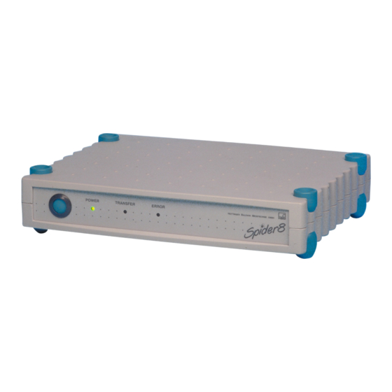
Page 41: Front Panel
Structure of the PC measurement electronics with Spider8 Ý Front panel B-15 Front panel LEDs On/off switch The three LEDs show you the operating status of the device. After switching on, the LEDs light up POWER (green) TRANSFER (yellow) ERROR (red) After a successful system start the green LED stays on. - Page 42 B-16 Structure of the PC measurement electronics for Spider8 Ý Front panel The LEDs have the following meaning: POWER The function test has been successfully completed and the Spider8 is ready for service. TRANSFER The Spider8 is sending or receiving data.
-
Page 43: C Commissioning
Commissioning Commissioning Spider8... - Page 44 Commissioning Spider8...
- Page 45 Adequate EMC protection cannot be guaranteed unless this is done. Update firmware: Existing Spider8 can be brought up to date with the Spider8 System • Connect the existing Spider8 to the COM1 or COM2 port of the PC with the serial cable.
-
Page 46: Installing Modules
Commissioning Ý Installing modules 1.1 Installing modules 1. Remove the four caps (A) from the top of the Spider8 housing Cover (prise them up with your thumb). 2. Undo the four screws (M4) with a cross-headed screwdriver. 3. Remove the cover. - Page 47 Fit the caps to the top of the housing. 8. Connect your PC to the Spider8 (see Chapter D ”Connecting a PC”). 9. Connect your transducer to the specially provided sockets on the back of the Spider8 (see Chapter D ”Connecting transducers”).
-
Page 48: Switching On Spider8
1. Connect the Spider8 to a PC (see page D-27). 2. Connect the Spider8 and the power pack provided to the mains supply. 3. Switch on the Spider8 with the POWER button on the front panel of the device. Position of On/Off switch: The Spider8 carries out a function test (all 3 LEDs light up briefly) and stores a record of the components that are present. -
Page 49: Installing Software
The main ones are described below: • When you start the installation program, you are asked to specify the drive and path for your installation. The default is c:\Spider8. Then confirm ”Install”. • If the specified directory does not exist, you are asked whether it should be created. - Page 50 ”WINSAVE” setup sub-directory. b. Installing Spider Control See Operating Manual Spider8 Control You have now taken all the necessary steps to make sure that your measurement chain (Spider8 and transducers) is ready for use. Spider8...
-
Page 51: D Connecting
Connecting Connecting Spider8... - Page 52 Connecting Spider8...
-
Page 53: Shielding Design
Shielding design Until now: In the case of shielding connections that have been customary with HBM up to now, the shielding is linked to a connector pin. This solution provides only limited EMC protection and should no longer be used. -
Page 54: Connecting A Power Pack
Connecting up Ý Connecting up a power pack Connecting a power pack Connect the power pack to the 13VDC IN socket. Spider8... -
Page 55: Connecting Transducers
Channels not used must be covered by blank plates. Channels 4 to 7: optional carrier-frequency or DC amplifier modules (SR55 , SR01, SR30 Channels 0 to 3: internal carrier-frequency modules Spider8 only for Spider8-30 only for see also table on page A-9... - Page 56 Connecting Ý Connecting transducers The following transducers can be connected to the Spider8: Transducer 4.8kHz carrier-fre- 600Hz carrier-fre- DC module quency module quency module Channel Channel Channel S/G full bridge 0...7 0...7 S/G half bridge 0...7 0...7 S/G quarter bridge 0...7...
- Page 57 Connecting Ý Connecting transducers Use the transducer cable directly for connecting or use additional KAB133A adapter cable. Connecting to a carrier-frequency module (15-pin socket, sub-D Spider8: Channels 0-3 connector Bu): (optionally 4-7) D The transducer cable is unterminated: Fit a 15-pin connector (see Fig. D 1) (Ord.
- Page 58 15-pin socket sub-D transducer connection connector Bridge excitation voltage 15-pin Measurement signal Measurement signal Spider8 Sensor circuit Sensor circuit Length of cable: 0.3m Transducer Diameter of cable: 7.5mm MS3101A 16S-1S Fig. D 2: Adapter cable with 7-pin MS-coupler socket Spider8...
- Page 59 (-) and sensor circuit (+) to bridge excitation voltage (+). A cable must only ever be extended using six-wire connection. Measurement signal (+) Bridge excitation voltage (-) Bridge excitation voltage (+) Measurement signal (-) Cable shielding Sensor circuit (+) Feedback Sensor circuit (-) bridges Spider8...
- Page 60 2. Undo the 5 screws. 3. Insert the cable ends into the terminal block. DC module with mounted 4. Secure the cable with screws. 5-pin terminal block 5. Close the plastic flap. connector 6. Mount terminal block connector on DC module in Spider8. Spider8...
-
Page 61: S/G Transducers
- Nominal sensitivity (for S/G transducers e.g. 2mV/V) - Resistance: maximum 1kΩ, minimum 120Ω Typical S/G transducers are load cells and force transducers. 15-pin socket Measurement signal Measurement signal Bridge excitation voltage Bridge excitation voltage 3’ Sensor circuit 2’ Sensor circuit Spider8... - Page 62 D-12 Connecting Ý Connecting transducers Connection to carrier-frequency module SR55, SR30 3.1.2 S/G half bridge 15-pin socket Measurement signal 15-pin socket Bridge excitation voltage Bridge excitation voltage 3’ Sensor circuit 2’ Sensor circuit Spider8...
-
Page 63: Single S/G Using Three-Wire Connection
Single S/G using three-wire connection 15-pin socket Bridge excitation voltage Active S/G 2’ 15-pin socket Sensor circuit e.g. rosette Measurement signal Free Free = compensating resistor Bridge excitation voltage Every R error also affects the S/G 3’ Sensor circuit measurement uncertainty Spider8... - Page 64 D-14 Connecting Ý Connecting transducers Connection to Spider8-30 Connection to carrier-frequency module SR30 3.1.4 Single S/G using three-wire connection 15-pin socket 15-pin socket Bridge excitation voltage 120Ω 2’ Sensor circuit (open) 350Ω Link open 700Ω Measurement signal Compensating resistor (internal): Pin3: 120Ω...
-
Page 65: Special S/G Using Three-Wire Connection (Increasing The Internal Compensating Resistance)
Connecting Ý Connecting transducers D-15 Connection to Spider8-30 Connection to carrier-frequency module SR30 3.1.5 Special S/G using three-wire connection (Increasing the internal compensating resistance) 15-pin socket 15-pin socket Bridge excitation voltage 120Ω to 2’ Sensor circuit (open) 1000Ω Link open... - Page 66 D-16 Connecting Ý Connecting transducers Connection to Spider8-30 Connection to carrier-frequency module SR30 3.1.6 Special S/G using three-wire connection (External compensating and shunt resistor) 15-pin socket 15-pin socket Bridge excitation voltage 120Ω to 2’ Sensor circuit (open) 1000Ω Measurement signal...
-
Page 67: Inductive Transducers
- Nominal sensitivity (e.g. 10mV/V) Typical inductive transducers are displacement transducers. 15-pin socket Measurement signal Measurement signal Bridge excitation voltage Bridge excitation voltage 3’ Sensor circuit 2’ Sensor circuit Inward core movement: display + outward core movement: display - Spider8... -
Page 68: Inductive Half Bridge
Inward core movement: display + outward core movement: display - Measurement signal 15-pin socket Measurement signal Bridge excitation voltage Bridge excitation voltage 3’ Sensor circuit 2’ Sensor circuit It is not permissible to connect a 3-wire cable that is longer than 3 metres. Spider8... -
Page 69: Dc Voltage Sources
Connecting Ý Connecting transducers D-19 3.3 DC voltage sources Connecting to DC module SR01 (Spider8-01) 5-pin socket mounted Ground, potential-segregated terminal connector "10V Connecting to carrier-frequency module* 15-pin socket Zero operating voltage 15-pin socket (ground) "10V * Cables Kab 133A and Kab 134A cannot be used... - Page 70 D-20 Connecting Ý Connecting transducers Connecting to DC module SR01 (Spider8-01) Transmitter with external supply voltage 5-pin socket 0 . . .+20mA mounted terminal connector Input resistance for Ground, DC power sources: potential- 5 Ω segregated Supply voltage Spider8...
-
Page 71: Dc Power Sources
Connecting Ý Connecting transducers D-21 3.4 DC power sources Connecting to DC module SR01 (Spider8-01) 5-pin socket mounted terminal connector Ground, = 5 Ω potential- segregated ±20mA; ±200mA Spider8... -
Page 72: Resistors
D-22 Connecting Ý Connecting transducers 3.5 Resistors Connecting to DC module SR01 (Spider8-01) Connecting Pt100, resistor, single S/G 5-pin socket mounted terminal connector Current feed Measurement signal + Measurement signal Ground Spider8... -
Page 73: Potentiometer
Potentiometric transducers are passive transducers. Example: potentiometric displacement transducer with a nominal displacement of 10mm. 15-pin socket 15-pin socket Measurement signal Bridge excitation voltage Bridge excitation voltage 3’ Sensor circuit 2’ Sensor circuit Programming: S/G half bridge Measuring range 500mV/V Spider8... -
Page 74: Thermocouples
Thermocouple with reference element in the DC module Thermocouples are active transducers. The benchmark measuring point is located in the transducer connector. Spider8 performs cold-spot compensation for thermocouples of the J, K, T and S type. The compensated and non-compensated measured value can be output. - Page 75 Error: 2.5°C - 5°C Thermocouple S: Resolution max.: 1°C Error: 25°C - 50°C Thermocouple with thermal reference element Reference measuring point 5-pin terminal Cu wires Extension wires Thermocouple Ground, potential- segregated Thermal reference element in iced water at 0 Spider8...
-
Page 76: Frequency Measurement / Pulse Counters
Pin10= Directional signal for metering pulse 1 backwards or metering pulse 2 input, 90 offset to metering pulse 1 Pin 9 and Pin 10: max. "20V, Switching threshold High u2.5V, Low t2V Pin 3: Clear = counter reset u850µs Spider8... -
Page 77: Connecting A Pc
D MS Windows 3.1 or MS Windows for Workgroups D CPU: 80486 D 8MB RAM D hard disk space for program installation Setup: Spider8 Control: 10MB Catman: 20MB D RS-232 port for serial connection of measuring systems D Microsoft or 100% compatible mouse... - Page 78 Parallel port (LPT1): Printer port (parallel, LPT1) D Connect an IEEE1284 cable to the PC D Connect the cable to the PC/Master socket on the Spider8 Other PCs (e.g. Mac) or if printer interface not available: COM1, COM2 serial port...
-
Page 79: Connecting Several Spider8 Devices
1. Connect an IEEE1284 cable to the PC With the first Spider8, switching on lights up the power indicator. 2. Connect the cable to the PC/Master socket on the first Spider8 With every subsequent Spider8 3. Connect the PRINTER/Slave socket on the first Spider8 to the... - Page 80 In mixed operation, the devices are connected as described on Page D-29. NOTE If you already have a Spider8(SR55 module) and want to operate it together with a Spider8-30(SR30) in mixed operation, you must also load the new Spider8-30 software on the Spider8.
-
Page 81: Connecting A Printer
1. Connect the printer cable to the PRINTER/Slave socket (25-pin) on the Spider8. 2. Connect the cable to the printer (36-pin printer socket). Follow the same procedure if using several Spider8 devices (see also Chap. 4.2). The printer cable is not included in the list of components supplied. - Page 82 D-32 Connecting Ý Connecting a printer Spider8...
-
Page 83: E Configuring The Spider8 With The Setup Program
Configuring the Spider8 with the setup program Configuring the Spider8 with the setup program Spider8... - Page 84 Configuring the Spider8 with the setup program Spider8...
-
Page 85: Setup Program
Configuring the Spider8 with the setup programÝ Setup program Setup program The setup program simplifies the way you operate the Spider8. With this program you can • configure the device, • display the current measured values and • carry out taring. - Page 86 Configuring the Spider8 with the setup programÝ Setup program Start setup*: • From the Windows interface select the symbol with a double-click. This starts the setup program. You are now in the setup dialogue. To see which settings can be displayed and changed, refer to Chapter 1.1...
-
Page 87: The First Display
Configuring the Spider8 with the setup programÝ Setup program 1.1 The first display 1. In the WINDOWs screen double-click on Spider8 Setup 2. After you have started the setup program, the following dialogue box is displayed : Enter device name... - Page 88 Parallel port Once you have chosen your settings and confirmed them with OK, (the correct interface settings for the Spider8 have already been made and do not usually need to be changed), you will again see the illustration shown on Page E-5.
- Page 89 Nibble mode: This operating mode works with any standard parallel interface. The data bytes from the Spider8 are sent sequentially as 4 bit packages (nibbles) via the status circuits. Data transfer rate: 13 000 bytes/s (6500 samples/s)
- Page 90 Configuring the Spider8 with the setup programÝ Setup program Byte mode: Transfer from the Spider8 to the PC takes place via data lines, which are switched from the normal direction (output) to input (two-way operation) in order to do this. Most modern computers allow this type of programming.
- Page 91 Configuring the Spider8 with the setup programÝ Setup program Here, the terms ”Standard”, ”Compatible”, ”AT” are used for the basic function and ”two-way” or ”PS/2” for the activation of byte mode. If ”EPP” is offered for selection, there can still be a distinction, for example in ”EPP1.7”...
- Page 92 E-10 Configuring the Spider8 with the setup programÝ Setup program You are now in the setup dialogue. All settings are entered in the setup program using the cursor (mouse pointer). Spider8...
-
Page 93: Description Of The Setup Dialogue
Configuring the Spider8 with the Setup program Ý Description of the setup dialogue E-11 1.2 Description of the setup dialogue Operation in online mode: In online mode the Spider8 is connected. You can carry out all the settings described in this chapter, such as marking channels, choosing a measuring range, taring. - Page 94 E-12 Configuring the Spider8 with the Setup program Ý Description of the setup dialogue Example: measuring range You want to change the measuring range for channel 3 to 12mV/V. 1. Click on channel 3 under the Meas. Rng. function. A pop-up list box is displayed. The currently selected setting is identified by a tick.
- Page 95 Configuring the Spider8 with the Setup program Ý Description of the setup dialogue E-13 Text box: A text box is displayed for the function Tare value. A text box consists of a rectangular area distinguished from the surrounding area by a different background colour. A text box is where you type data (maximum two lines, 20 characters) that cannot be presented for selection in list form.
- Page 96 E-14 Configuring the Spider8 with the Setup program Ý Description of the setup dialogue Option boxes: Option boxes are displayed for the functions Tare and Shunt. An option box lets you choose one of several alternative options (Yes/No). Select status: This status shows that an option is active.
- Page 97 Configuring the Spider8 with the Setup program Ý Description of the setup dialogue E-15 Buttons: A button is a rectangular graphic element with a three-dimensional appearance. A button is activated by selecting it with the mouse-button. In the case of a button, the action is not executed until you release the selection button on the mouse whilst the pointer is still on the screen button.
- Page 98 E-16 Configuring the Spider8 with the Setup program Ý Description of the setup dialogue Menu bar File Edit Device Options Help Various functions can be accessed via the menu bar (pull-down menu): File Load Setup Save Setup Save Setup As...
- Page 99 Configuring the Spider8 with the Setup program Ý Description of the setup dialogue E-17 You can save in one of two ways: Save Setup: • The current setting is stored as a file. • If the settings are being saved for the first time, you must enter a name and select the required directory.
- Page 100 E-18 Configuring the Spider8 with the Setup program Ý Description of the setup dialogue File Edit Undo All Settings Select All Channels Deselect All Channels Undo All Settings: • The changes you have made since starting the program are cancelled. The pre-existing parameters are valid once again.
- Page 101 Configuring the Spider8 with the Setup program Ý Description of the setup dialogue E-19 Channel numbering for several Spider8 units goes up in tens. Example: First Spider8: Channel 0...8 Second Spider8: Channel 10...18 File Edit Device Options Logfile On Show Logfile...
-
Page 102: Mark Channels
E-20 Configuring the Spider8 with the Setup program Ý Description of the setup dialogue 1.3 Mark channels By simultaneously marking several channels, the settings for these channels can be executed at the same time. If you set up one channel, the settings for this channel will be transferred to the other marked channels, as long as this is possible. - Page 103 Configuring the Spider8 with the Setup program Ý Description of the setup dialogue E-21 Marking non-consecutive channels You do not want to select channels en bloc. 1. Position the cursor in the ”Mark” column alongside the first channel you want to mark (e.g. channel 2). Click with the mouse to mark the channel.
-
Page 104: Channel-Specific Menus
Selection bar: The selection bar shows you the functions necessary for setting up the Spider8. Functions will be explained from left to right (each in turn shown on a grey background). In addition you need the device-specific functions for setting up (see page E-30). - Page 105 Configuring the Spider8 with the Setup program Ý Channel-specific menus E-23 Configure your individual Spider8 devices (channels) with the following functions. Mark Chan. Name Trans. Meas. Rng. Filter Tare Shunt Tare Val. Meas. Value Name: The channel name is displayed.
- Page 106 E-24 Configuring the Spider8 with the Setup program Ý Channel-specific menus Mark Chan. Name Trans. Meas. Rng. Filter Tare Shunt Tare Val. Meas. Value Transducer: Channel-dependent transducer connection Chan. Transducers that can be connected Carrier frequency Carrier module Full bridge...
- Page 107 Configuring the Spider8 with the Setup program Ý Channel-specific menus E-25 Explanation: Signal edges: If only 1 signal is measured, one signal edge is counted. Signal edges and direction: If 2 signals are measured: the first channel measures pulses (one signal edge), the second channel defines the direction (ascending or descending).
- Page 108 E-26 Configuring the Spider8 with the Setup program Ý Channel-specific menus Mark Chan. Name Trans. Meas. Rng. Filter Tare Shunt Tare Val. Meas. Value Measuring range: The available measuring ranges are displayed in accordance with the transducer selected. Transducer Meas. Rng.
- Page 109 Configuring the Spider8 with the Setup program Ý Channel-specific menus E-27 Mark Chan. Name Trans. Meas. Rng. Filter Tare Shunt Tare Val. Meas. Value Transducer Meas. Rng. Chan. 0.1V DC voltage 4...7 (SR01) 20mA DC current 4...7 (SR01) 200mA 400Ω...
- Page 110 E-28 Configuring the Spider8 with the Setup program Ý Channel-specific menus Mark Chan. Name Trans. Meas. Rng. Filter Tare Shunt Tare Val. Meas. Value Filter: You can choose between a fixed filter and a variable filter. Selectable filter types (var.): Bessel, Butterworth, Average value (see page E-32).
- Page 111 Configuring the Spider8 with the Setup program Ý Channel-specific menus E-29 Mark Chan. Name Trans. Meas. Rng. Filter Tare Shunt Tare Val. Meas. Value Tare value: You can view the current tare value or enter a required tare value. 0.00005 Mark Chan.
-
Page 112: Device-Specific Menus
E-30 Configuring the Spider8 with the Setup program Ý Device-specific menus Device-specific menus Device: Spider8 Sampling Rate Filter Type (var.) Filter Frequency Zero balance Test Device... Bessel 20Hz Zero balance: Zero balancing is carried out for all channels where ”Tare” has been selected. - Page 113 Configuring the Spider8 with the Setup program Ý Device-specific menus E-31 Test Device: • Click on the Test Device button. The device carries out a component test. The following dialogue box is then displayed: Changing from one Spider8 to the next: <<<...
- Page 114 E-32 Configuring the Spider8 with the Setup program Ý Device-specific menus Samplingrate: The amplifier modules deliver measured values with a data transfer rate of between 1 and 9600 measured values/s. Depending on the sampling rate chosen, different filter frequencies are available for selection.
- Page 115 Configuring the Spider8 with the Setup program Ý Device-specific menus E-33 Impulse response Best frequency response (Butterworth) The figure exhibits linear amplitude response which falls away steeply above the cut-off frequency. There is an overshoot of about 10%. Best course over time (Bessel) Best frequency response The figure exhibits a impulse response with very little (<1%) or no...
- Page 116 E-34 Configuring the Spider8 with the Setup program Ý Device-specific menus The following table shows the choice of filter frequencies for the Spider8 and the Spider8-30. Sampling rate as a function of cutoff frequency: see example on following page Cutoff frequency f (Hz) Ý...
- Page 117 Configuring the Spider8 with the Setup program Ý Device-specific menus E-35 If you change the sampling rate, what effects does this have on the filter frequency? 1. If possible, the filter frequency selected during set-up is used. 2. If this is not possible, the filter frequency is modified by as little as possible when compared with the frequency last used (see fields in table on previous page).
- Page 118 E-36 Configuring the Spider8 with the Setup program Ý Device-specific menus Spider8...
-
Page 119: F Specifications
Specifications Specifications Series Spider8 / SR55 Spider8-30 / SR30 Spider8-01SR01 Accuracy class Digital resolution in the case of full scale value Digit "25000 Measurement buffer Meas < 20000 Baud rate serial 600, 1200, 2400, 4800, 9600, 19200, 38400, 57600 parallel... - Page 120 2.75 / 0.05 0.05 Connections Transducer DB-15 socket DB-15 socket SUBCON 5-pin socket Digital I/O DB-25 socket RS-232 computer interface DB-9 socket Printer port DB-25 socket PC interface DB-25 socket nly for the Spider8 basic device (channels 0 to 3) Spider8...
- Page 121 230V, P nominal approx. 82 EMV requirements The following standards are satisfied: DIN EN61326 Dynamic mains undervoltages with any notch depth and any notch duration can lead to the switching off of the device, but not to its destruction. Spider8...
- Page 122 However, if you open the device up, you must be aware that the input circuit still carries over 100V DC for some time after the mains voltage is switched off. Spider8...
-
Page 123: G Keyword Index
Keyword index Keyword index Spider8... - Page 124 E-31 computer, B-6 DC module, D-10 , D-19 , D-20 , D-21 , D-22 , E-24 DC power sources, D-21 DC voltage sources, D-19 digital I/O, B-3 , E-29 digital inputs, B-11 DLL program, A-4 EMC protection, D-3 Spider8...
- Page 125 S/G full bridge, D-11 modules, C-3 S/G half bridge, D-12 carrier-frequency, DC, D-5 sampling rate, E-32 selection bar, E-22 Setup offline mode, E-11 , E-22 load, E-16 online mode, E-11 , E-22 print, E-17 save, E-16 option box, E-14 setup, E-4 Spider8...
- Page 126 SR55, B-5 , D-11 , D-12 , D-13 , D-17 , D-18 , D-23 , D-26 transducer cable, D-7 , D-10 switching on, B-15 transducer connection, D-7 trigger, B-11 tare, E-28 , E-29 taring, E-28 zero balance, E-30 terminal block connector, D-10 Spider8...
-
Page 127: H Declaration Of Conformity
Declaration of conformity Declaration of conformity Spider8... - Page 128 Declaration of conformity Spider8...
- Page 129 Declaration of conformity Spider8...
- Page 130 Declaration of conformity Spider8...
- Page 132 They are not to be understood as express warranty and do not constitute any liability Postfach 10 01 51, D-64201 Darmstadt whatsoever. Im Tiefen See 45, D-64293 Darmstadt Tel.: +49/61 51/8 03-0; Fax: +49/61 51/ 8039100 E-mail: support@hbm.com www.hbm.com B0405-7.0 en...