Table of Contents
Advertisement
Quick Links
Advertisement
Table of Contents

Subscribe to Our Youtube Channel
Related Manuals for HBM DMP41


Summary of Contents for HBM DMP41
- Page 1 Operating manual English DMP41 Digital precision measuring instrument...
- Page 2 Fax +49 6151 803-9100 info@hbm.com www.hbm.com Mat.: 7-0102.0003 DVS: A03470_07_E00_00 HBM: public 03.2020 E Hottinger Baldwin Messtechnik GmbH. Subject to modifications. All product descriptions are for general information only. They are not to be understood as a guarantee of quality or...
-
Page 3: Table Of Contents
..........DMP41 A03470_07_E00_00 HBM: public... - Page 4 ......... . DMP41 A03470_07_E00_00 HBM: public...
- Page 5 ................DMP41 A03470_07_E00_00 HBM: public...
- Page 6 DMP41 A03470_07_E00_00 HBM: public...
-
Page 7: Safety Instructions
General dangers of failing to follow the safety instructions The DMP41 is state of the art and failsafe. The DMP41 may give rise to residual dangers if it is inappropriately installed and operated by untrained personnel. - Page 8 50% at 40°C. S The DMP41 is classified in overvoltage category II, degree of pollution 2. S Install the DMP41 so that it can be disconnected from the mains at any time without difficulty. S It is safe to operate the DMP41 up to a height of 2000 m.
- Page 9 Never pull the mains plug out of its socket by the supply lead. Do not operate the DMP41 if the mains lead is damaged. If you need to re place the mains cable, order a new one with ordering number 1-KAB274-…...
- Page 10 S Emission (EME): Class B (see Note) S Immunity to interference: Industrial environment Note on emission (EME): The DMP41 is supplied ex works i.a. with a mains cable and an adapter cable (USB to RS232). These cables are fitted with ferrites to minimize emission (EME) and must not be removed.
- Page 11 Conversions and modifications The DMP41 must not be modified in terms of design or safety engineering except with our express agreement. Any modification shall exclude all liability on our part for any resultant damage.
- Page 12 The measuring circuits of the DMP41 are not assigned to any measurement category as per DIN EN 61010-2-030. Qualified personnel The DMP41 is only to be installed and used by qualified personnel strictly in accordance with the specifications and with the safety rules and regulations which follow.
-
Page 13: Symbols On The Instrument
The electrical and electronic devices that bear this symbol are subject to the European waste electrical and electronic equipment directive 2012/19/EU. The symbol indicates that the DMP41 must not be disposed of as household garbage. In accordance with national and local environmental protection... - Page 14 Symbols on the instrument DMP41 A03470_07_E00_00 HBM: public...
-
Page 15: Introduction
S The document interface description and command set, explaining programming and measurement with PC or terminal. This manual contains all the information required to operate the DMP41. Several guides are available to you: S To help you quickly find the information you require, there is a full list of contents at the front of the operating manual. - Page 16 Look upon this operating manual as part of the product and keep it so that it is accessible to all users, all of the time. If you pass the DMP41 on to a third party, always pass it on together with the requisite documentation.
-
Page 17: The Markings Used In This Document
The black triangle at the start of a paragraph marks the start of an instruc tion to be followed. A, B, C, 1, 2, 3 Blue letters and numbers are used for labeling in keys to the images. DMP41 A03470_07_E00_00 HBM: public... -
Page 18: Scope Of Supply
Digital precision measuring instrument DMP41 interface description and command set 1 system CD 1-KAB297 USB-RS232 adapter (from the new USB interface of the DMP41 to the RS232 interface previously present on the DMP40) 1-KAB2114-3 RS232 cable (null modem cable) Accessories (not included in the scope of supply) -
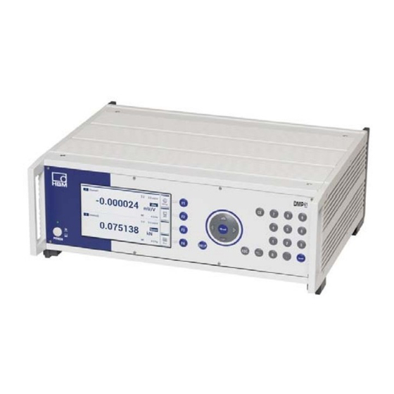
Page 19: Device Overview
Introduction Device overview Device overview The DMP41 is available in the following two enclosure versions (each with 2 or 6 amplifiers): S Desktop housing S 19” rack-mount case Desktop housing Device version Number of Temperature Power supply amplifiers channels DMP41-T2... - Page 20 Introduction Device overview 19” rack-mount case Corresponds to 3 rack units 465.5 Device version Number of Temperature Power supply amplifiers channels DMP41-E2 230 V/115 V ~ DMP41-E6 230 V/115 V ~ DMP41 A03470_07_E00_00 HBM: public...
-
Page 21: Front Of Device
Activates the settings that have been made Escape key Resets the last entry in menus or selection fields (excluding text fields) and closes the online help Help key Activates the online help for the functions currently activated On/Off switch DMP41 A03470_07_E00_00 HBM: public... -
Page 22: Back Of Device
RJ45 1-Wire® temperature sensors Housing ground Mains connection Grounding switch Ethernet network USB host (RS232 adapter, keyboard, USB flash drive, etc.) Synchronization of several DMP41s Full bridge strain gage transducer; MS cable connector, 7-pin, MS3106A 16S-P DMP41 A03470_07_E00_00 HBM: public... - Page 23 RJ45 1-Wire® temperature sensors Housing ground Mains connection Grounding switch Ethernet network USB host (RS232 adapter, keyboard, USB flash drive, etc.) Synchronization of several DMP41s Full bridge strain gage transducer; MS cable connector, 7-pin, MS3106A 16S-P DMP41 A03470_07_E00_00 HBM: public...
-
Page 24: Principle Of Operation
Principle of operation This section explains the basic working method of the DMP41. Up to six measuring points can be connected to the DMP41. Auxiliary variables such as the measuring point temperature or an external voltage can be displayed in parallel with the strain gage signal. -
Page 25: Electrical Connections
The NT040 power supply is designed for a 115/230 V connection. The power supply fan is temperature-controlled and is automatically switched on only when necessary. The DMP41 must be connected to a socket with a grounding protective conductor using the supplied mains cable. -
Page 26: Transducer Connection
Amphenol socket. Simultaneous connection of transducers in both sockets will result in incorrect measurement results. Full bridge strain gage transducer; D-sub, 15-pin, DA-15P (HBM ordering number 3-3312.0182) Full bridge stain gage transducer; MS cable connector, 7-pin, MS3106A 16S-P (HBM ordering number 1-MS3106 PEMV) DMP41 A03470_07_E00_00 HBM: public... -
Page 27: Connection Options
Electrical connections Transducer connection 4.2.1 Connection options Measured quantity Full bridge strain gage Temperature measurement (1-Wire® sensor) Important Only connect strain gage transducers in a 6-wire configuration. DMP41 A03470_07_E00_00 HBM: public... -
Page 28: Full Bridge Strain Gages
Cable color code: wh= white; bk= black; bu= blue; rd= red; ye= yellow; gn= green; gy= gray The LEDs above the connection sockets indicate the operating status of the measuring point: LED green = Measuring point active LED off = Measuring point passive LED red = Error LED orange = Transducer identification DMP41 A03470_07_E00_00 HBM: public... - Page 29 The LEDs above the connection sockets indicate the operating status of the measuring point: LED green = Measuring point active LED off = Measuring point passive LED red = Error LED orange = Transducer identification TEDS transducer identification omitted in this connector version. DMP41 A03470_07_E00_00 HBM: public...
-
Page 30: Temperature Sensors
Cable color code: wh= white; bu= blue; WARNING An electric shock can be fatal or cause serious injury ► Make sure that all the metallic surfaces to which the temperature sensor is attached (glued, clamped) are voltage-free. DMP41 A03470_07_E00_00 HBM: public... -
Page 31: Tid (Transducer Identification)
A special circuit makes it possible to use the existing wires for transferring TEDS data. This allows the same cables to be used as for transducers with out TEDS. The switch is made between a measuring mode (the lead transfers the ana DMP41 A03470_07_E00_00 HBM: public... - Page 32 Voltage supply + 16 V Voltage supply - 16 V Zero-wire: Between 2 and 2' Between B and G Cable color code: wh= white; bk= black; bu= blue; rd= red; ye= yellow; gn= green; gy= gray DMP41 A03470_07_E00_00 HBM: public...
-
Page 33: Inputs And Outputs, Remote Controls
DIGITAL IN/OUT Outputs/inputs Designation Not in use GND/IN IN 3 SYNC IN 1 GND OUT OUT 3 OUT 1 +24 V external GND/IN IN 4 IN 2 GND OUT OUT 4 OUT 2 +24 V external DMP41 A03470_07_E00_00 HBM: public... - Page 34 +24 V The voltage at the output is approx. 0.5...1 V lower than the externally con nected supply voltage. The maximum current depends on the strength of the external supply voltage, but must not exceed 0.5 A. DMP41 A03470_07_E00_00 HBM: public...
-
Page 35: Pc Connection
S PC connection via RS232 (with USB serial adapter) PC connection via Ethernet /Ethernet switch 1 . . . n PCs (Clients) USB HOST Ethernet switch or Ethernet HUB ETHERNET 1 . . . n DMP41 DMP41 A03470_07_E00_00 HBM: public... - Page 36 Electrical connections PC connection PC connection via USB serial adapter 1 PC n PCs (with n serial interfaces) (one RS232 each) USB HOST USB serial adapter 1 DMP41 1 adapter ETHERNET DMP41 A03470_07_E00_00 HBM: public...
- Page 37 Electrical connections PC connection Connection examples Connecting one DMP41. USB- RS232 adapter* HOST Ethernet Recommended connection Alternative possible connections with restrictions DMP41 A03470_07_E00_00 HBM: public...
- Page 38 Electrical connections PC connection Connecting several DMP41s (with recommended Ethernet connection) HOST SYNC.OUT Ethernet HOST Ethernet SYNC.IN 1 . . n Switch DMP41 A03470_07_E00_00 HBM: public...
-
Page 39: Synchronization
DMP41s are synchronized. This is necessary so that the generators are not mutually disruptive as the carrier frequencies of the various DMP41s are never exactly identical. This would otherwise lead to a crosstalk of the car rier frequency from one DMP41 to the measurement signal of another 1-WIRE DMP41. - Page 40 DMP41s. The status of the synchronization connection is displayed. The total length of the synchronization chain (total cable length between SYNC.OUT of the first DMP41 and SYNC.IN of the last DMP41) must be less than 100 m. SYNC.OUT device 1...
- Page 41 Electrical connections Synchronization PIN assignments of the synchronization sockets SYNC.OUT SYNC.IN Pin assignment SYNC.OUT SYNC.IN Designation Designation Start-A Start-A Start-B Start-B Ready-A Ready-A Master-A Slave-A Master-B Slave-B Ready-B Ready-B Master ID Master ID Ground Ground DMP41 A03470_07_E00_00 HBM: public...
- Page 42 Electrical connections Synchronization DMP41 A03470_07_E00_00 HBM: public...
-
Page 43: Starting Up
The DMP41 power supply is designed for a 115/230 V connection. The voltage is automatically adapted to the existing mains voltage. ► Switch the DMP41 on using the POWER button on the front of the device (the launch display appears immediately). - Page 44 Starting up Switching on Start screen on the PC Start screen on the DMP41 Information è For more information on the start screens, see Chapter 6.4.1 “The first display”, Page 56. DMP41 A03470_07_E00_00 HBM: public...
-
Page 45: Installing The Operating Software
Installing the operating software: ► Insert the supplied system CD into your PC drive. ► Double-click on the setup file. ► Select Install DMP41 Client Software in the following dialog. The DMP41 is connected to your computer. DMP41 A03470_07_E00_00 HBM: public... -
Page 46: Important Information Before Measurement
S the measuring points are unshielded and are close together. If synchronizing several DMP41s, use a standard networking cable (synchronization cable 1-KAB287-3) for connecting the SYNC sockets on è the back of the DMP41 ( also see Chapter 4.5 “Synchronization”, starting on Page 39). DMP41... - Page 47 S DMP41 without connected PC: Operate using the keys on the front panel S DMP41 with connected keyboard (via the USB port): Operate by means of this keyboard and/or the front panel keys S DMP41 with connected PC and keyboard and mouse:...
- Page 48 Activates the settings that have been made Escape key Resets the last entry in menus or selection fields (excluding text fields) and closes the online help Help key Activates the online help for the functions currently activated On/Off switch DMP41 A03470_07_E00_00 HBM: public...
- Page 49 Confirm with Operation via the front panel keyboard You can make all the settings for your DMP41 by means of the control keys on the front panel. There are two operating modes available, measuring mode (Measure) and setting mode (Settings).
- Page 50 S Configuring Channels: measuring range, filter, scaling, channel name, display accuracy, zeroing, peak values, copy, save, load S Configuring Device: password, terminal, display brightness, information, logging, factory settings, device name, date/time, update S Configuring Interfaces: Ethernet, RS232 DMP41 A03470_07_E00_00 HBM: public...
- Page 51 Operation Control elements Overview of the touchscreen user interface PC operation only Setting mode Measuring mode Quick configuration bar Operation via cursor keys, mouse, touch, back with F4 or Selected channels Act on the selected channels DMP41 A03470_07_E00_00 HBM: public...
- Page 52 Shift key for measuring mode (Measure) setting mode (Settings) Shift key for the number of displayed measurement channels (1, 2, 4, 6) Connection/disconnection of the DMP41 (PC operation only) Quick configuration bar and back (hide quick configuration bar again) Function keys F1 to F4 are effective in both measuring mode and setting mode, but have different functions.
- Page 53 The channel parameters can be selected from a pop-up menu in the functions Signal, Unit, Aux and Channel. Aux: Temperature T1 All selected channels display the temperature T1 Channel: Channel 4 All the selected channels show Channel 4 in the set properties (e.g. unit, gross, net). DMP41 A03470_07_E00_00 HBM: public...
- Page 54 Function keys in setting mode (Settings) Shift key for setting mode (Settings) / measuring mode (Measure) Enters numbers or letters in the display Saves edited settings Back to previous level F2 to F4: Display and function depend on the level DMP41 A03470_07_E00_00 HBM: public...
- Page 55 DMP41 or by using key F5 on the keyboard during PC operation. Operation via PC (with mouse and keyboard) You have connected the DMP41 to a PC. Operation via PC is equivalent in all functions to keyboard operation. Use the mouse pointer to click on menu items, drop-down texts or links.
- Page 56 Display/TouchScreen 6.4.1 The first display After the mains voltage is switched on, the DMP41 is initialized and detects the components that are present. This procedure takes approx. 45 seconds. Start screen on the PC The PC start screen shows the selectable, connected DMP41s. General information about the selected DMP41 will also be displayed.
- Page 57 Unit Measured value Shift key for measuring mode/setting mode Shift key for the number of displayed measurement channels (1, 2, 4, 6) Connection/disconnection of the DMP41 (PC operation only) To the quick configuration bar (and back) DMP41 A03470_07_E00_00 HBM: public...
- Page 58 The channel parameters can be selected from a pop-up menu in the functions Signal, Unit, Options and Channel. è Also see Chapter 6.2 “Function keys in measuring mode (Measure)”, starting on Page 52. DMP41 A03470_07_E00_00 HBM: public...
- Page 59 Zero value = 0.5 mV/V Gross Tare value = 0.25 mV/V mV/V 0.75 (relative to tare value 0.25 mV/V) The following values appear in the display for this example: Absolute 1.5 mV/V Gross 1.0 mV/V 0.75 mV/V DMP41 A03470_07_E00_00 HBM: public...
- Page 60 Operation Display/TouchScreen 6.4.3 Display in setting mode (Settings) The screens shown on the PC and the DMP41 may differ (no direct screen correlation). Function keys bar Measurement channel settings (Channel) Bridge excitation voltage and measuring range Filter Scaling Device settings (Device)
- Page 61 Example: Settings Shift key for measuring mode (Measure) → setting mode (Settings) Keys Key input via display Save Saves edited settings Back Back to previous level Entering letters or numbers. Deleting characters with the CE key. DMP41 A03470_07_E00_00 HBM: public...
- Page 62 Operation Display/TouchScreen DMP41 A03470_07_E00_00 HBM: public...
- Page 63 Basic configuration options Configuration This chapter looks at the functions and configuration options of the DMP41. The menu structures shown below will help you find the required setting menus more rapidly. We also show you at the same time the actual key sequences to follow to make the settings.
- Page 64 Configuration Basic configuration options Additional settings (if necessary) Filter View/delete peak values (Min/Max) Set display formats (Resolution and Step) Settings such as password, name and brightness can be made under Device (device settings). DMP41 A03470_07_E00_00 HBM: public...
- Page 65 è Inputs via this menu only act on the selected channels ( also see Chapter 6.1 “Control elements”, starting on Page 48). Information The inputs in setting mode do not depend on the channels marked here. DMP41 A03470_07_E00_00 HBM: public...
- Page 66 The maximum accuracy as stated in the specifications is only achieved with settings of 10 V for the excitation voltage and 2.5 mV/V for the measuring range. The bridge excitation voltage selection can restrict the choice of measuring range. DMP41 A03470_07_E00_00 HBM: public...
- Page 67 Linearization compensates for the non-linearities of the transducer. In the scaling dialog, values with up to 7 decimal places are shown accurately, with the 7th digit rounded off (example: 200 kg remain exactly 200 kg in the linearization table, not 199.999) DMP41 A03470_07_E00_00 HBM: public...
- Page 68 If values lie outside the stated scaling points, the gradient of the last two scaling points is used and extrapolated accordingly. ► Press Scaling. ► Choose a unit (A). ► Chose the values for unit and mV/V for each scaling point. ► Press Save. DMP41 A03470_07_E00_00 HBM: public...
- Page 69 S Tare value Applies the adjacent electrical value as the zero value Applies the adjacent electrical value as the tare value Applies the adjacent (scaled) physical value as the zero value Any unit (set in Scaling) DMP41 A03470_07_E00_00 HBM: public...
- Page 70 Important When zeroing the mV/V value, the user-defined unit is set in accordance with the characteristic curve (non-zero). F2 or When zeroing the user-defined unit, the mV/V is set in accordance with the characteristic curve (non-zero). DMP41 A03470_07_E00_00 HBM: public...
- Page 71 ► Press Filter. ► Select BE, 1 Hz for the individual channels (corresponds to damping of > 90 dB at 12 Hz). ► Press Save. ► Press shift key F1 to return to measuring mode (Measure). scrollin DMP41 A03470_07_E00_00 HBM: public...
- Page 72 With fast dynamic signals, you must take into account that the peak values are determined from the filtered signal. If, in the above example, the peaks of the the foundation oscillations are to be measured, the filter must be set to more than 12 Hz. DMP41 A03470_07_E00_00 HBM: public...
- Page 73 ► Press (C). The peak values are deleted. - Via a computer using the command CPV - Directly via (quick configuration bar) ► Press shift key F1 to switch to measuring mode (Measure). ► Press Clear (D). DMP41 A03470_07_E00_00 HBM: public...
- Page 74 The channel names can also be overwritten with the name of the Master channel (C). Example: Channels 2, 3, 4 and 6 are renamed as Channel1. Copies all the settings from channel 1 to channels 2, 3, 4 and 6. DMP41 A03470_07_E00_00 HBM: public...
- Page 75 ► Select the channel to be set. ► Enter the increment (Step) for the user-defined unit. ► Enter the resolution for the user-defined unit. ► Enter the increment (Step) for mV/V. ► Enter the resolution for mV/V. DMP41 A03470_07_E00_00 HBM: public...
- Page 76 ► Press F2 and assign a name to the selected parameter set (delete letters and characters with the CE key). ► Press OK. ► Press Save. Here: saves all the param eter sets of all 6 channels under the number 9. DMP41 A03470_07_E00_00 HBM: public...
- Page 77 3 (A). ► Confirm with Load (B). The channels affected by the changes are identified by a green checkmark. The channel settings saved in parameter set number 9 are written over to channel 2 only. DMP41 A03470_07_E00_00 HBM: public...
- Page 78 ► Press more..► Press TID. If there is no TID connected: No TID detected If a TID is connected: The TID number is displayed Detects whether an identification module (T-ID) for strain gages is connected. DMP41 A03470_07_E00_00 HBM: public...
- Page 79 This password protection (for working directly on the DMP41) is switched off in the factory setting. If the DMP41 is operated via a PC, it is always necessary to enter a pass word. As soon as password protection is activated, the password must be entered whenever the DMP41 is restarted.
- Page 80 Password protection OFF: ► Press Password. ► Enter the password. ► Under Ignore password, select: Yes. Important The password can be ignored when working on the DMP41. The password must never be ignored when working with a PC! DMP41 A03470_07_E00_00 HBM: public...
- Page 81 ► Enter the current password (A). ► Enter a new password (B). ► To confirm the new password, enter it for a second time (C). ► Confirm and save with Change. The password becomes visible (here: 12345) DMP41 A03470_07_E00_00 HBM: public...
- Page 82 The password is then reset to the default password "1234". è If you want to set a different password, proceed as described in Chap ter 7.3.1.2 “Change password”, Page 81. Important The password can only be reactivated on the the DMP41 (not via PC). DMP41 A03470_07_E00_00 HBM: public...
- Page 83 Configuration Device configuration in setting mode 7.3.2 Device name You can allocate a name to each DMP41 in your device network. ► Press Name. ► Press F2 and assign a name. ► Press Save. DMP41 A03470_07_E00_00 HBM: public...
- Page 84 Setting the waiting time before the display brightness is dimmed (Dim after (seconds)): If no input occurs on the DMP41 (by keyboard or touch operation) for some time, the display brightness is reduced to the set dimmed brightness after the set waiting time has elapsed (1 to 3600 seconds).
- Page 85 Configuration 7.3.4 Factory settings (Factory Set) Overview of the DMP41 factory settings and explanation of their selective resetting The channel, device and interface settings can be returned to their respective factory settings. Below is a detailed list of the settings that can be reset:...
- Page 86 Configuration 7.3.5 Synchronization status (Sync Status) You can query the synchronization status for each DMP41 in your device network. ► Press more..► Press Sync Status. The following messages may appear: Slave connected Synchronization complete Synchronizing Synchronization ongoing xx %...
-
Page 87: Device Component Information (Info)
S Operating system version S Device serial number S Number of connected clients (other DMP41s connected to a PC) This information serves to identify the DMP41 and in the event of a fault, is sent to HBM together with the log file. DMP41... -
Page 88: Date/Time
The network time is not taken over, even if connected to a PC. The clock starts working once the time has been entered and saved. Information The Date/Time is only available for operation via the DMP41 (not for operation via PC). ► Press more.. -
Page 89: Command Input Via The Keyboard (Terminal)
7.3.8 Command input via the keyboard (Terminal) It is always possible with the DMP41 to also use command shortforms when making settings and carrying out measurements. This dialog is firstly in tended for service purposes and secondly for programmers who want to test the commands to be sent by a software in interactive operation. -
Page 90: Logging
The properties of the log file can be defined for troubleshooting (e.g. com munication errors between the DMP41 and the PC). The log file is only of interest when the DMP41 is not working as expected. You can then specify which events should be recorded in the log and you can transfer the log file to a USB flash drive. -
Page 91: Certificate
► Press more..► Press Certificate. ► Insert a USB flash drive into the USB HOST socket on the back of the DMP41 device. ► Press Copy certificate to USB stick. The certificate is copied to the USB flash drive. -
Page 92: Configuring Interfaces In Setting Mode
DMP41 is switched on. Additional parameters (subnet mask, gateway address) can also be specified by the network administrator and these will then also be set. - Page 93 Configuration Configuring interfaces in setting mode Information The Ethernet function is only available for operation via the DMP41 (not for operation via PC). ► Press Ethernet. ► Select DHCP OFF or ON. OFF : You can enter values for “IP address, Network mask and Gateway”...
-
Page 94: Rs232 Interface
Configuring interfaces in setting mode 7.4.2 RS232 Interface Information The RS232 function is available for operation via the DMP41 and for operation via a PC. ► Press RS232. ► Enter the values for Baud rate, Parity and Stop bits. ► Press Save. -
Page 95: Updating The Firmware And Operating Software
► Run the Setup file on a Windows computer. The Update file will be copied to the USB flash drive. ► With the DMP41 switched off, insert the USB flash drive into the USB USB HOST HOST socket on the back of the DMP41. - Page 96 The actual update process then starts, and can last for approx. 4 minutes. The bar indicates the progress of the process. Once the update process is successfully completed, the following message appears: The following have been re-installed: S Interface S Operating system S FPGA S Firmware DMP41 A03470_07_E00_00 HBM: public...
-
Page 97: Typical Configuration Example
► Press Scaling and select the unit kg (C). ► Use the keypad to make entries in the edit fields (D): Point 1: 0.000 kg and 0.000 mV/V Point 2: 50.000 kg and 2.500 mV/V ► Press Save (diskette symbol). Range Scaling DMP41 A03470_07_E00_00 HBM: public... - Page 98 ► Press Resolution and set the display formats (e.g. Resolution 0.000; Step 1) (B). ► Press Save (diskette symbol). ► Press Zero. ► Delete Zero value and Tare value (E). ► Use shift key F1 to switch to measuring mode. DMP41 A03470_07_E00_00 HBM: public...
- Page 99 ► Press Unit and select the required unit (here: User = kg in the display) (B) ► Place the container on the scale. Measuring mode ► Press Tare to zero (C). ► Pour the bulk material into the container. The weight of the bulk material is displayed. DMP41 A03470_07_E00_00 HBM: public...
- Page 100 Configuration Typical configuration example DMP41 A03470_07_E00_00 HBM: public...
-
Page 101: Error Messages/Remedial Action
S Signal within range (Signal in the measuring range (no overflow detected)) S Excitation (excitation voltage) S TID (TID detected) S Calibration status Press the HELP key on the front of the device to call up the meanings of the channel status (error messages). DMP41 A03470_07_E00_00 HBM: public... - Page 102 A TEDS module has been detected, the module ID has been read out. The TEDS information is not yet evaluated in the current version, only the (worldwide) unique ID is read out. No TEDS module has been detected. DMP41 A03470_07_E00_00 HBM: public...
- Page 103 (Cal) for a channel. The error limit can lie outside the device tolerance. In the DMP41 specifications, all channels can be used to measure while an Autocal process is being run. Measurement is not interrupted or affected. The information table shows which channel is in a calibration cycle.
- Page 104 Error messages/remedial action DMP41 A03470_07_E00_00 HBM: public...
-
Page 105: Technical Support
Technical support Technical support Should you have any questions when working with the DMP41, you can contact HBM's technical support in the following ways: E-mail support info@hbm.com HBM on the Internet http://www.hbm.de Downloading software updates from HBM http://www.hbm.com/Software Headquarters world-wide... - Page 106 Technical support DMP41 A03470_07_E00_00 HBM: public...
-
Page 107: Keyword Index
35 Enclosure, 19 Command shortform, entry, 89 Error messages, 101 Configuration example, 97 Excitation, 66 Connecting one DMP41, 37 several DMP41s, 38 Connection examples, 37 Factory settings, 85 Connection options, 27 Filter frequency, 71 Connector sockets. See Back of device... - Page 108 NT040 power supply, 25 Ethernet, 92 RS232, 94 Online help, 55 Keypad, 21, 48, 55, 97 Password changing, 81 Linearization and scaling, 67 lost, 82 Load, 76 protecting, 79 Logging, 85, 90 Password protection, 80 Low-pass filter, 71 DMP41 A03470_07_E00_00 HBM: public...
- Page 109 Scaling and linearization, 67 USB, Serial adapter, 36 Setting mode, 50, 60 User interface, Overview, 51 Settings, 50, 54 Signal type, 59 Specifications, 105 Zero, 69 Start screen, 44, 56 Zeroing, 69 Status information, Channels, 101 DMP41 A03470_07_E00_00 HBM: public...
- Page 110 Keyword index DMP41 A03470_07_E00_00 HBM: public...
- Page 111 Keyword index DMP41 A03470_07_E00_00 HBM: public...
- Page 112 HBM Test and Measurement Tel. +49 6151 803-0 Fax +49 6151 803-9100 info@hbm.com measure and predict with confidence...
Need help?
Do you have a question about the DMP41 and is the answer not in the manual?
Questions and answers