HBM MP60 Operating Manual

HBM MP60 Operating Manual

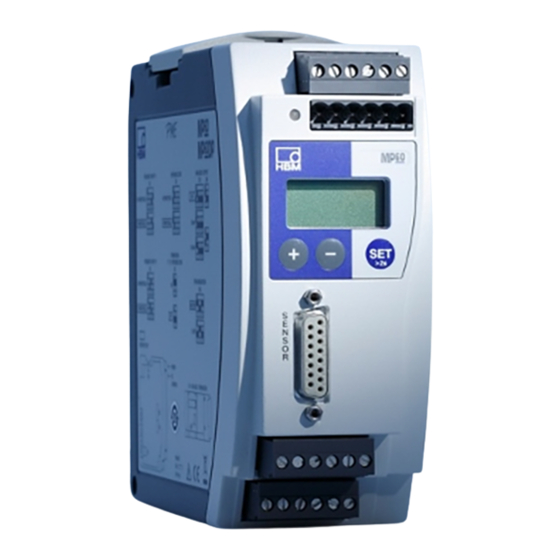
Pme industrial measurement electronics with fieldbus link

Advertisement

Operating manual
PME industrial
measurement electronics
with fieldbus link
MP60/MP07
A0616-13.4 en

Advertisement

Table of Contents
loading

Summary of Contents for HBM MP60

  • Page 1 Operating manual PME industrial measurement electronics with fieldbus link MP60/MP07 A0616-13.4 en...
  • Page 3: Table Of Contents

    4.2 Supply voltage and control inputs/outputs MP60 ....4.2.1 External supply voltage for control outputs (MP60) ..4.3 Supply voltage MP07 .
  • Page 4: Safety Instructions

    The supply connection, as well as the signal and sense leads, must be installed in such a way that electromagnetic interference does not adversely affect device functionality (HBM recommendation: ”Greenline shielding design”, downloadable from the Internet at http://www.hbm.com/Greenline). Automation equipment and devices must be covered over in such a way that adequate protection or locking against unintentional actuation is provided (such as access checks, password protection, etc.).
  • Page 5 PME-MP60/MP07 Use in accordance with the regulations The MP60 and MP07 module and their connected transducers may be used for measurement tasks only and directly related control tasks. To ensure safe operation, the transducer may only be used as specified in the operating manual.
  • Page 6 PME-MP60/MP07 Residual dangers The scope of performance and supply of the MP60 or MP07 covers only part of the measurement technology. In addition, equipment planners, installers and operators should plan, implement and respond to the safety engineering considerations of measurement technology in such a way as to minimize re- sidual dangers.
  • Page 7 Greenline shielding only (conncect the shield of the transducer cable to the plug housing). The cables of the digital inputs and outputs of the MP60/MP60DP should not be longer than 30 m or should they be routed outside the building where the system is located.
  • Page 8 Conversions and modifications HBM’s express consent is required for modifications affecting the transdu- cers’s design and safety. HBM does not take responsibility for damage resul- ting from unauthorized modifications. The product is delivered from the factory with a fixed hardware and software configuration.
  • Page 9: Introduction

    HBM T10F-SF1 and T10F-SU2 torque flanges. The MP60 module is set up and parameters assigned via the keyboard and display or with the aid of the PME Assistent. The PME Assistent gives you a simple operator interface under MS-Windows for assigning parameters to the modules (described in the ”PME Assistent”...
  • Page 10 The following HBM torque transducers may derive their excitation from an MP07 module: T10F-KF1, T30FNA, T32FNA, T34FN, T36FN The MP07 module, like the MP60, is connected to a 24 V supply voltage and delivers the following output voltages (short-circuit proof): +15 VDC, 100 mA...
  • Page 11: Selecting Amplifier Settings With Dip Switches

    PME-MP60/MP07 Selecting amplifier settings with DIP switches NOTE The adjustment/alteration of DIP switch settings must take place before mounting the PME. Various settings are defined with the aid of DIP switches. These are the settings for terminating resistance, frequency input signals, input connection...
  • Page 12 PME-MP60/MP07 Factory settings: Bottom S10, S11, S12 and circuit board: motherboard: S4, S5 and S6 Analogue output (10 V) 1 2 3 1 2 3 4 5 6 1 2 3 4 5 6 1 2 3 1 2 3 4 5 6...
  • Page 13 PME-MP60/MP07 Factory settings: Input signal asymmetric / symmetric Analogue output "10 V Frequency source F1 1 2 3 4 5 6 1 2 3 symmetric asymmetric "20 mA 1 2 3 4 5 6 1 2 3 4 5 6...
  • Page 14 PME-MP60/MP07 Synchronization Master 1 2 3 4 5 6 Slave 1 2 3 4 5 6 Fig. 2.4: Setting up the amplifier (continued) Terminating bus resistor Toggle switch for termination resistor (see page 25) Fig. 2.5: Toggle switch for termination resistor...
  • Page 15: Mounting/Dismounting The Mp60/Mp07

    PME-MP60/MP07 Mounting/dismounting the MP60/MP07 Fig. 3.1: Mounting on a support rail Fig. 3.2: Dismounting A0616-13.4 en...
  • Page 16 PME-MP60/MP07 Fig. 3.3: Fitting of a second spring fore more stable mounting of the module on the DIN rail CAUTION The support rail must be on protection circuit potential A0616-13.4 en...
  • Page 17: Connecting Several Modules

    Fig. 3.4: Connecting the flat ribbon cable Several MP60 or MP07 modules may be connected over one flat ribbon cable. This cable is used for local connection of the supply voltage and synchronization between the modules. You should not interconnect more than 8 modules with one flat ribbon cable.
  • Page 18: Connections

    Connections WARNING Please take note of the safety instructions before putting the device into operation. 4.1 Functional overview of MP60/MP07 Local linking of CAN-bus, supply voltage and synchronization between the modules Terminal plug 1: MP60 Voltage supply and CAN-bus, Synchronization...
  • Page 19: Supply Voltage And Control Inputs/Outputs Mp60

    4.2 Supply voltage and control inputs/outputs MP60 Four removable terminal plugs are provided for connection. Connect voltage supply Warning The MP60 module must be connected to an external voltage supply of 18-30 V (24 V nom. D Twist wires of the voltage supply and fit end sleeves for strands.
  • Page 20: External Supply Voltage For Control Outputs (Mp60)

    PME-MP60/MP07 4.2.1 External supply voltage for control outputs (MP60) Example: PLC connection MP60 module Relay max. 100 mA OUT3 max. 100 mA OUT1 24 V* 0 V* 0 V* Terminal plug 4 Fig. 4.2: Connection to a PLC Control inputs are provided at terminal plug 3 and control outputs at terminal plug 4, and are electrically isolated internally from the supply voltage (see also Chapter 6, ”Declaring the significant parameters”...
  • Page 21: Supply Voltage Mp07

    Fig. 4.3: Pin assignment for terminal plug 1 See Chapter 4.4 NOTE Use standard HBM cable for the transducer connection. When using other shielded, low-capacitance measuring cable, connect the trans- ducer cable shielding to the connector housing in accordance with the HBM Greenline concept (Internetdownload http://www.hbm.com/Green-...
  • Page 22: Connecting A Transducer

    Measurement signal for rotation speed, 0° , F1 (+) Measurement signal for rotation speed, 0° , F1 (-) Measurement signal for rotation speed, 90° , F2 (-) Hsng. Cable shielding Measurement signal for rotation speed, 90° , F2 (+) Transducer error Fig. 4.4: Connection for MP60 A0616-13.4 en...
  • Page 23 (5 - 30 V) peak-to-peak (90° out-of-phase for detection Transducer of direction of rotation) shaft Hsng. Cable shielding Measurement signal for rotation speed, F1 (+), 25 V (5 - 30 V) peak-to-peak Transducer error Fig. 4.5: Connection for MP60 and MP07 A0616-13.4 en...
  • Page 24 Fig. 4.6: Connection for MP60 NOTE The MP60(DP) can indicate the transducer errors generated by the tor- que sensor. But to do this, the error signal from the torque sensor must be connected across Pin 7 of the transducer plugs (15−pin sub−D plugs) on the MP60(DP).
  • Page 25: Can Interface

    The CAN-bus needs a terminating resistance of 120 Ω in the first and last bus users. A terminating impedance is integrated into the MP60 module which is activated by the S14 DIP switches (see page 14).
  • Page 26: Synchronization (Mp60)

    PME-MP60/MP07 4.6 Synchronization (MP60) Synchronization of modules guarantees the simultaneous acquisition and processing of measurement data. Slave Master 1 2 3 4 5 6 1 2 34 5 6 Fig. 4.9: Set up master/slave When synchronising several modules, one device is to be declared as the master.
  • Page 27: Setting Up And Operation (Mp60)

    PME-MP60/MP07 Setting up and operation (MP60) 5.1 Operating principles Display in measuring mode: Measured value -18.00 Status field Unit ↓ ↑ Flashes in status field, if parameter value is editable These keys are pressure-sensitive: Hold key down - values run through (the harder you press, the faster they run...
  • Page 28 PME-MP60/MP07 Measuring mode Password status active Password status inactive (factory setting): 2 secs. 2 secs. DIALOG PASSWORD Set-up mode Enter password: Password ↓ ↑ Input mode Enter required password (factory setting 0) Confirm Example: Enter numerical Select table value value...
  • Page 29 PME-MP60/MP07 During measurement you can press - view on display: 1. measured value 2. analogue output value 3. status of digital I/Os 4. the error list The symbol is displayed in the status field , this indicates an error which is described in the error list.
  • Page 30: Commissioning

    If the error message HardwOvf is displayed at this point, please refer to the Chapter called 8 ”Error messages” for further details. In addition, the yellow LED indicates that the MP60 is ready to start measuring. You will find the meanings of other LED signals in the chapter called 8 ”Error messages”.
  • Page 31: Guide To All Groups And Parameters

    5.3 Guide to all groups and parameters Groups PARAM. TRANSD.- ANALOG LIMIT VAL. PEAKVAL. PROFI- ADDITION DIALOGUE DISPLAY TRANSDUCER CONDITIoNING IN/OUT CAN-BUS CALIBRAT OUTPUT 1..4 STORE FUNCTION Password Load ? DecPoint Unit P1Meas.? >0< Set ? SourceVo Enable Enable Output1 Baudrate Address AmplType...
  • Page 32: Set Up All Parameters

    5.3.1 Set up all parameters 2sec A0616-13.4 en HBM Meas. value PassStat active Groups Transducer DISPLAY PARAM. SET PASSWORD DIALOGUE .00000 ↓ ↑ ↓ ↑ ParaS.1 ↓ ↑ _ _ _ _ Password _ _ _ _ Password ↓ ↑...
  • Page 33 Zero kNm 0.000 ↓ ↑ Bessel FiltChar Butterw l/mi ↓ ↑ NVal kHz 0.00000 Back to ↓ ↑ MAINGRP NVal kNm 0.00000 Back to ↓ ↑ Trans Err MAINGRP Back to depending on the unit selected A0616-13.4 en HBM MAINGRP...
  • Page 34 Groups A0616-13.4 en HBM Analog output PEAKVAL. CAN-BUS IN / OUT LIMIT VAL.1 LIMIT VAL.2...4 STORE LimVal1 ↓ ↑ LimVal2 LimVal3 Enable LimVal4 ↓ ↑ Output1 ↓ ↑ Enable Motion Error Accordingly Pulse Gross Output2..4 ↓ ↑ Source inactiv InputMin ↓...
  • Page 35 ↓ ↑ Slow Gross ↓ ↑ Keyboard Fast Output Medium PkValMax PkValMin PkVal PP HW-Vers Back to MAINGRP ↓ ↑ OutR. ms ↓ ↑ float PDO-Frmt int32 ↓ ↑ AutoOPER Back to MAINGRP depending on the unit selected A0616-13.4 en HBM...
  • Page 36: Example: Measuring Md And N With Torque

    PME-MP60/MP07 5.4 Example: measuring Md and N with torque transducer T10F (24 V supply) Both the T10F and the MP60 are set to symmetrical signals at the factory. Torque measurement Measurement preparation: Use the standard cable md-cab149. " Connect the 24 V external supply voltage to terminal plug 4 as well (see "...
  • Page 37 PME-MP60/MP07 The T10F is set by using sensitivity. To achieve greater accuracy, you must use the integrated shunt to calibrate the T10F. Calibration with integrated shunt: The transducer must be load−free! Group: TRANSD.-CALIBRAT P1Meas.? YES (corresponds to zero point measurement)
  • Page 38 PME-MP60/MP07 Enter T10F characteristic values: Group: TRANSDUCER Unit: U/min Input range: 1 MHz Zero index (+) Frq x 4 Direction of rotation (only possible if F1 and F2 are active) Switching threshold 2.5 V Glitch filter Zero kHz Zero U/min...
  • Page 39: Declaring The Significant Parameters

    PME-MP60/MP07 Declaring the significant parameters Group Parameters Meaning DIA− Password Specifying (changing) a password, 0000 - 9999 LOGUE (Factory preset password: 0000) PassStat Define password status: active=password must be entered; inactive=PME can be operated without a password I.ParaS to Access to group via keyboard free or locked.
  • Page 40 The direction of rotation information is analysed when F2 is activated . A negative direction of rotation as defined by HBM is shown by a - (minus) sign. Threshol Switching threshold from which the input signal is detected Suppresses interference spikes with a duration of t3.2 μs...
  • Page 41 PME-MP60/MP07 Group Parameters Meaning CONDITIO >0< kNm Enter zero value. Zeroing effects both, the gross value and NING the net value. >0< Set ? Trigger zero balance; current measurement value (physical unit) zero >0< save Each time there is a zeroing procedure the zero value is adopted into the EEPROM (service life 100.000 cycles)
  • Page 42 PME-MP60/MP07 Group Parameters Meaning ANALOG SourceVo You can choose the gross or net values, as well as the peak OUTPUT value as the source of the analogue signal. Mode Vo Use DIP switches S11 to specify the signal mode for the analogue output.
  • Page 43 PME-MP60/MP07 Group Parameters Meaning LIMIT VAL. Source You can select one of the following as the source of the limit 1...4 value signal: Gross, Net, Peak value Max/Min/Peak-to-peak SwtchDir Functions and parameters of limit values Value LVS1, ON Value Hyst...
  • Page 44 PME-MP60/MP07 Inputs /Outputs Terminal plug 3: provided here for the control of PME functions are 4 inputs. Terminal plug 4: Here you have 4 outputs available. Group Parameters Meaning IN/OUT Output Outputs 1 - 4 can be assigned the following functions for each...
  • Page 45 PME-MP60/MP07 Group Parameters Meaning IN/OUT PkMomMax ”Peak value” operating mode PkMomMin Measurement signal PkHldMax PkHldMin Trend of stored value Hold Hold Function Operating Peak value (Store1) Current value mode ”Current value” operating mode Measurement signal Hold Function Operating Current value...
  • Page 46 PME-MP60/MP07 Group Parameters Meaning ADDITION >0<Rf Referenznull FUNCTION Ein Wegaufnehmer 〈"20 mm Nennmeßweg) ist vom Fun- dament aus gemessen in einer Höhe von 1 m befestigt. Bei einem Nullsetzen wird der Analogausgang auf 0 V abgegli- chen. Der Anzeigewert wird auf >0<Ref (+1000 mm) abgeg- lichen.
  • Page 47: Can Interface Description (Mp60 Only)

    CAN interface description (MP60 only) 7.1 General The MP60 module has a built-in CAN interface, via which both measured values (data) can be transferred and parameters can be assigned to the module. You are free to select the baud rate, but the maximum is 1 MBaud.
  • Page 48: Parameter Assignment

    Á Á Á Á Á Á Á Á Á Á Á Á Á Á Á Writing a parameter: Send value (PC or PLC on MP60/MP07) Á Á Á Á Á Á Á Á Á Á Á Á Á Á Á Á Á Á Á Á Á Á Á Á...
  • Page 49 Á Á Á Á Á Á Á Á Á Á Á Á Á Á Á Response in the event of an error when reading or writing parameters: Error acknowledge (MP60/MP07 on PC or PLC) Á Á Á Á Á Á Á Á Á...
  • Page 50: Object Directory (Communications Profile Section)

    PME-MP60/MP07 7.4 Object directory (communications profile section) Communications profile section according to CAN-open (CIA-DS301) Index Sub- Name Data type Attr. Values Á Á Á Á Á Á Á Á Á Á Á Á Á Á Á Á Á Á Á...
  • Page 51 PME-MP60/MP07 Á Á Á Á Á Á Á Á Á Á Á Á Á Á Á Á Á Á Á Á Á Á Á Á Á Á Á Á Á Á Á Á Á Á Á Á Á 1801 0..2 2.
  • Page 52 PME-MP60/MP07 SDO parameter: Á Á Á Á Á Á Á Á Á Á Á Á Á Á Á Á Á Á Á Á Á Á Á Á Á Á Á Á Á Á Á Á Á Á Á Index Subindex...
  • Page 53: Emergency Objects

    PME-MP60/MP07 7.5 Emergency objects Á Á Á Á Á Á Á Á Á Á Á Á Á Á Á Á Á Á Á Á Á Á Á Á Á Á Á Á Á Á Á Á Á Á Á Á Á...
  • Page 54: Object Directory: Manufacturer-Specific Objects

    PME-MP60/MP07 7.6 Object directory: manufacturer-specific objects Parameters relating to measured values are coded with figures scaled in the appropriate range as Long (32 bit integer). The position of the decimal point is defined in the object 2120Hex. Alternatively, these quantities are also available as floating decimal point values (IEEE754-1985 32 Bit format) (see page 64).
  • Page 55 PME-MP60/MP07 Á Á Á Á Á Á Á Á Á Á Á Á Á Á Á Á Á Á Á Á Á Á Á Á Á Á Á Á Á Á Á Á Á Á Á Á Á Á Á Á...
  • Page 56 PME-MP60/MP07 Á Á Á Á Á Á Á Á Á Á Á Á Á Á Á Á Á Á Á Á Á Á Á Á Á Á Á Á Á Á Á Á Á Á Á Á Á Á Index...
  • Page 57 PME-MP60/MP07 Á Á Á Á Á Á Á Á Á Á Á Á Á Á Á Á Á Á Á Á Á Á Á Á Á Á Á Á Á Á Á Á Á Á Á Á Á Á Index...
  • Page 58 PME-MP60/MP07 Á Á Á Á Á Á Á Á Á Á Á Á Á Á Á Á Á Á Á Á Á Á Á Á Á Á Á Á Á Á Á Á Á Á Á Á Á Á Index...
  • Page 59 PME-MP60/MP07 Á Á Á Á Á Á Á Á Á Á Á Á Á Á Á Á Á Á Á Á Á Á Á Á Á Á Á Á Á Á Á Á Á Á Á Á Á Index Sub-...
  • Page 60 PME-MP60/MP07 Á Á Á Á Á Á Á Á Á Á Á Á Á Á Á Á Á Á Á Á Á Á Á Á Á Á Á Á Á Á Á Á Á Á Á Á Á Á Index...
  • Page 61 PME-MP60/MP07 Á Á Á Á Á Á Á Á Á Á Á Á Á Á Á Á Á Á Á Á Á Á Á Á Á Á Á Á Á Á Á Á Á Á Á Á Á Á Index...
  • Page 62 PME-MP60/MP07 Á Á Á Á Á Á Á Á Á Á Á Á Á Á Á Á Á Á Á Á Á Á Á Á Á Á Á Á Á Á Á Á Á Á Á Á Á Á Index...
  • Page 63 PME-MP60/MP07 Á Á Á Á Á Á Á Á Á Á Á Á Á Á Á Á Á Á Á Á Á Á Á Á Á Á Á Á Á Á Á Á Á Á Á Á Á Á Index...
  • Page 64: Manufacturer-Specific Objects In Floating Data Format

    PME-MP60/MP07 7.7 Manufacturer-specific objects in floating data format Á Á Á Á Á Á Á Á Á Á Á Á Á Á Á Á Á Á Á Á Á Á Á Á Á Á Á Á Á Á Á Á Á Á Á Á Á...
  • Page 65 PME-MP60/MP07 Á Á Á Á Á Á Á Á Á Á Á Á Á Á Á Á Á Á Á Á Á Á Á Á Á Á Á Á Á Á Á Á Á Á Á Á Á Index Sub-...
  • Page 66: Examples

    PME-MP60/MP07 7.8 Examples Example 1: Reading the net measured value as a floating value using SDO transfer from the amplifier with Module address 3. Protocol at the amplifier: Á Á Á Á Á Identifier Á Á Á Á Á Á Á Á Á...
  • Page 67: Error Messages/Operating Status (Led)

    PME-MP60/MP07 Error messages/operating status (LED) Depending on the display mode, various error messages may be displayed in place of the measured value: Signal status (mode) possible error message Grs+Ovf CntrOvfl Scal.Err - - - - - - - Grs-Ovf Init Err...
  • Page 68 40 NOTE The MP60(DP) can indicate the transducer errors generated by the tor- que sensor. But to do this, the error signal from the torque sensor must be connected across Pin 7 of the transducer plugs (15−pin sub−D plugs) on the MP60(DP).
  • Page 69 PME-MP60/MP07 Operating status: Status Meaning colour Measuring mode Bus mode Green Steady Ready to take measurements CAN Operational (PDO transfer light possible) Green Flashing Data is transferred via the interface Yellow Steady Ready to take measurements CAN-bus Pre-operational (no PDO...
  • Page 70 PME-MP60/MP07 A0616-13.4 en...
  • Page 71 PME-MP60/MP07 A0616-13.4 en...
  • Page 72: Keyword Index

    CAN interface, 25 error, 29 supply voltage, 19 error acknowledgement, 49 connecting a transducer, to an MP60, to error code, 52 an MP07, 22 error message, 30 , 67 , 68 connecting flat ribbon cable, 17 error messages, 29...
  • Page 73 PME-MP60/MP07 MP07, 10 , 17 , 18 , 48 factory settings, 12 , 13 filter, 41 object directory, 50 , 54 flat ribbon cable, 26 operating direction, 43 frequency quadrupling, 40 , 58 output characteristics, 42 function test, 30 output rate, 45...
  • Page 74 19 , 21 transducer excitation, 18 supply voltage MP07 , 21 trigger level, 58 supply voltage MP60, 19 Switch convention, 11 switching threshold, load, save, 40 value, 43 synchronisation, 18 , 26 voltage supply, 18 , 19 , 21...
  • Page 76 Hottinger Baldwin Messtechnik GmbH 7−2002.0429 Postfach 10 01 51, D-64201 Darmstadt Im Tiefen See 45, D-64293 Darmstadt Tel.: +49 6151 803-0 Fax: +49 6151 8039100 Email: support@hbm.com Internet: www.hbm.com A0616−13.4 en...

This manual is also suitable for:

Mp07

Table of Contents