HBM T40B Mounting Instructions
Combines a rotational speed measuring system and reference pulse in a single measurement flange
Hide thumbs
Also See for T40B:
- Mounting instructions (124 pages) ,
- Mounting instructions (120 pages) ,
- Mounting instructions (164 pages)
Table of Contents
Advertisement
Available languages
Available languages
Advertisement
Chapters
Table of Contents

Related Manuals for HBM T40B


Summary of Contents for HBM T40B
- Page 1 Mounting Instructions | Montageanleitung English Deutsch T40B...
- Page 2 Hottinger Baldwin Messtechnik GmbH Im Tiefen See 45 D-64239 Darmstadt Tel. +49 6151 803-0 Fax +49 6151 803-9100 Email: info@hbm.com Internet: www.hbm.com Mat.: 7-2002.3452 DVS: A3452-10.0 11.2014 E Hottinger Baldwin Messtechnik GmbH. Subject to modifications. All product descriptions are for general information only.
- Page 3 Mounting Instructions | Montageanleitung English Deutsch T40B...
-
Page 4: Table Of Contents
......Stator status, LED B (lower LED) ......A3452-10.0 T40B... - Page 5 ..... Supplementary technical information ..... . T40B A3452-10.0...
-
Page 6: Safety Instructions
The FCC identifier or the unique identifier, as appropri ate, must be displayed on the device. Model Measuring range FCC ID 50 Nm, 100 Nm, 200 Nm 500 Nm, 1 kNm T40S2TOS6 2ADAT−T40S2TOS6 12438A−T40S2TOS6 2 kNm, 3 kNm 5 kNm 10 kNm A3452-10.0 T40B... - Page 7 This device complies with part 15 of the FCC Rules. Operation is subject to the following two conditions: (1) This device may not cause harmful interference, and (2) this device must accept any interference received, including interference that may cause undesired operation. Fig. 1.2 Example of the label T40B A3452-10.0...
- Page 8 This product has not yet received IC (Industry Canada) approval. The certification process for this product is still under way. HBM currently expects that IC approval will be granted by the end of December 2014. Your local HBM contact looks forward to answer any questions you may have regarding IC approval.
- Page 9 Appropriate use The T40B torque flange is used exclusively for torque, angle of rotation and power measurement tasks within the load limits stipulated in the specifications. Any other use is not appropriate.
- Page 10 The only permitted exceptions to the above requirements are if the torque flange is already fully protected by the design of the machine or by existing safety precautions. A3452-10.0 T40B...
- Page 11 Transducers can break, particularly in the case of over loading. The breakage of a transducer can also cause damage to property or injury to persons in the vicinity of the transducer. T40B A3452-10.0...
- Page 12 You are familiar with the operation of the equipment and tech nologies described in this documentation. 3. As system startup engineers or service engineers, you have successfully completed the training to qual A3452-10.0 T40B...
- Page 13 Safety instructions ify you to repair the automation systems. You are also authorized to ground and label circuits and equipment and place them in operation in accordance with safety engineering standards. T40B A3452-10.0...
-
Page 14: Markings Used
CE mark The CE mark enables the manufacturer to guarantee that the product complies with the requirements of the rele vant EC directives (the Declaration of Conformity can be found on the HBM website at www.hbm.com under HBMdoc). Label example... - Page 15 This marking draws your attention to information about the product or about handling the product. Information Emphasis Italics are used to emphasize and highlight text and See…. references to other chapters and external documents. T40B A3452-10.0...
-
Page 16: Application
This offers a very wide range of applica tions. The T40B torque flange is reliably protected against elec tromagnetic interference. It has been tested according to harmonized European standards and/or complies with US and Canadian standards. -
Page 17: Structure And Mode Of Operation
Connector plugs for the torque and rotational speed sig nals, the voltage supply and digital output, are located on the stator. The antenna segments (the antenna ring) must be mounted concentrically around the rotor (see chapter 5). T40B A3452-10.0... - Page 18 The rotational speed sensor is mounted on the stator in Option 6 with a rotational speed measuring system. The rotational speed is measured magnetically via an AMR sensor and a magnetic ring. The magnetic ring for mea suring the rotational speed is welded to the flange. A3452-10.0 T40B...
- Page 19 (zero index) for measuring the angle of rotation. The magnet to be used for this is located on the inner surface of the flange. The sensor head for sampling the reference signal is located in the bracket above the rotational speed sensor. T40B A3452-10.0...
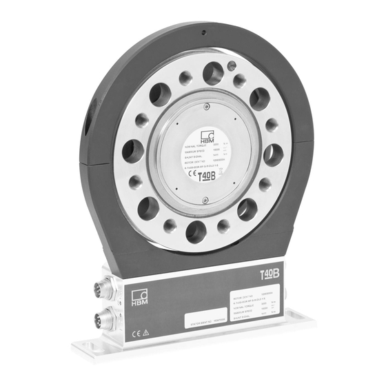
- Page 20 Sensor head for the rotational speed reference signal Connector plugs Connector Stator housing plugs Type plate Fig. 4.3 Mechanical construction with rotational speed measuring system and sensor for the reference signal (zero index), Option 7, Code S A3452-10.0 T40B...
- Page 21 Stator housing Connector plugs Fig. 4.4 Mechanical construction of Stator with mounted shielding plates without rotational speed Option 7, Code U Dismounted shielding plates Radial shielding plate Axial shielding plates Fig. 4.5 Individual shielding plates, Option 7, Code U T40B A3452-10.0...
- Page 22 The use of the shielding plates are important to ensure compliance with FCCregulations. If the shielding plates has to be removed for any purpose (e.g. in-stallation or maintenance), they must be replaced in the original posi tion be-fore the product is used. A3452-10.0 T40B...
-
Page 23: Mechanical Installation
Implement appropriate safety measures to avoid over loads and to protect against resulting dangers. S Use a threadlocker (medium strength, e.g. LOCTITE) to glue the screws into the counter thread to exclude T40B A3452-10.0... -
Page 24: Conditions On Site
(using an intermediate flange when required). Under no circumstances should the permissible limits specified for bending moments, lateral and longitudinal forces be exceeded. Due to the T40B torque flange's high torsional stiffness, dynamic shaft train changes are kept to a minimum. -
Page 25: Installation Orientation
90 kHz for Option 5, Code DU2 (Option 5, Code SU2: 10 to 15 kHz; Option HU2: 240 to 360 kHz). In conjunction with HBM amplifiers or when using the voltage output, a positive output signal (0 V to +10 V) is present. In the... -
Page 26: Installation Without Dismantling The Antenna Ring, Option 7, Code U With
Mechanical installation 5.4.1 Installation without dismantling the antenna ring, Option 7, Code U with antenna shielding cover Mounting supplied by customer 1. Install rotor 2. Install stator Support supplied by customer 3. Finish shaft train installation 4. Fit support A3452-10.0 T40B... -
Page 27: Installation With Subsequent Stator Mounting, Option 7, Code S
Mechanical installation 5.4.2 Installation with subsequent stator mounting, Option 7, Code S 1. Install rotor 2. Install shaft train Washers Fan‐type lock washers 3. Dismantle antenna segment 4. Install antenna segment Support supplied by customer 5. Fit support T40B A3452-10.0... -
Page 28: Installing The Rotor
Fig. 5.1 by using it to support tools, or knocking tools against it when tightening screws, for example. This can damage the transducer and pro duce measurement errors, or even destroy the trans ducer. A3452-10.0 T40B... - Page 29 (dependent on the connection geometry, see Tab. 5.1 on page 29). We recommend DIN EN ISO 4762 socket head cap screws, blackened, smooth‐headed, permitted size and shape variance in accordance with DIN ISO 4759, Part 1, product class A. T40B A3452-10.0...
- Page 30 Comply with the maximum thread reach as per Tab. 5.1. Otherwise significant measurement errors may result from torque shunt, or the transducer may be damaged. Measuring range Fastening screws Prescribed tightening moment Property class 10.9 10.9 10.9 10.9 10.9 10.9 12.9 A3452-10.0 T40B...
-
Page 31: Installing The Stator
Option 7, Code S. If your application does not require the stator to be dis mantled, proceed as described in points 2., 5., and 6 for Option 7, Code S. T40B A3452-10.0... - Page 32 Bolted connection of the antenna segments on the stator, Option 7, Code S Antenna segments with mounted shielding plates Stator housing Connector plugs Fig. 5.3 Mechanical construction of Stator with mounted shielding plates without rotational speed Option 7, Code U A3452-10.0 T40B...
- Page 33 Important If the shielding plates has to be removed for installation or maintenance, tighten the screws to fix the shielding plates with a tightening torque of 0.6 Nm T40B A3452-10.0...
- Page 34 Mechanical installation T40B without a rotational speed measuring system T40B with a rotational speed measuring system Sensor head for measuring rotational speed Stator housing Antenna wire lower antenna segment Fig. 5.5 Stator housing and lower antenna segment with antenna wire, Option 7, Code S 1.
- Page 35 To make this alignment easier, the antenna segment and the transmitter winding on flange B have the same width. Please comply with the permissible align ment tolerances stated in the specifications. T40B A3452-10.0...
- Page 36 (see Fig. 5.7, right). Information If the stator base is already securely installed, you must remove the upper antenna segment (see steps 1, 3 and 4). Otherwise proceed with the installation as shown in the photos. A3452-10.0 T40B...
- Page 37 (with an M5 internal thread) on the upper antenna seg ment, which can be used for a suitable clamping device (see Fig. 5.8). If this is the case, the cable plug also needs some support, as shown in the construction exam ple in Fig. 5.9. T40B A3452-10.0...
- Page 38 Mechanical installation Fig. 5.8 Construction example for supporting the antenna ring, Option 7, Code S and U Fig. 5.9 Construction example for plug clamps (for two plugs), Option 7, Code S and U A3452-10.0 T40B...
-
Page 39: Rotational Speed Measuring System, Reference Signal (Optional)
If the stator is accurately aligned for torque measure ment, the rotational speed measuring system and the sensor for the reference signal (zero index) are also cor rectly aligned. So the two Allen screws on the sensor head (Fig. 5.11) must not be loosened. T40B A3452-10.0... - Page 40 Never loosen the screws! Sensor head for measuring rotational speed Fig. 5.11 Torque transducer with sensor head for rotational speed measurement, Option 7, Code S and U A3452-10.0 T40B...
-
Page 41: Electrical Connection
S All cable connectors or swivel nuts must be fully tight ened. Important Transducer connection cables from HBM with plugs attached are identified in accordance with their intended purpose (Md or n). When cables are shortened, inserted into cable ducts or installed in control cabinets, this iden... - Page 42 With other connection tech niques, an EMCproof shield should be applied in the wire area, and this shielding should also be connected extensively (also see HBM Greenline Information, brochure i1577). Electrical and magnetic fields often induce interference voltages in the measuring circuit.
-
Page 43: Connector Pin Assignment
Note Torque flanges are only intended for operation with a DC supply voltage. They must not be connected to older HBM amplifiers with square‐wave excitation. This could destroy the connection board resistors or cause other faults in the amplifiers. T40B... - Page 44 Bridge between 4 + 9 RS-422 complementary signals; with cable lengths exceeding 10 m, we recommend using a termination resistor R = 120 ohms between the (wh) and (rd) wires. RS‐422: pin 1 corresponds to A, pin 4 corresponds to B. A3452-10.0 T40B...
- Page 45 Operating voltage zero bk/bl Shielding connected to housing ground Bridge between 4 + 9 RS-422 complementary signals; with cable lengths exceeding 10 m, we recommend using a termination resistor of R = 120 ohms. KAB163/KAB164: color code brown (bn) T40B A3452-10.0...
- Page 46 Operating voltage zero Shielding connected to housing ground Bridge between 4 + 9 RS-422 complementary signals; with cable lengths exceeding 10 m, we recommend using a termination resistor of R = 120 ohms. KAB163/KAB164: color code brown (bn) A3452-10.0 T40B...
- Page 47 Electrical connection Pin 1 Pin 6 Pin 3 Pin 7 Pin 2 Pin 4 Fig. 6.1 Rotational speed signals at plug 2 (rotational speed in the direction of the arrow) T40B A3452-10.0...
- Page 48 Electrical connection Pin 1 Pin 6 Pin 3 Pin 7 Pin 2 Pin 4 Fig. 6.2 Rotational speed signals at plug 2 (rotational speed against the direction of the arrow) A3452-10.0 T40B...
-
Page 49: Supply Voltage
Shielding connected to housing ground Assignment for plug 4 TMC - only for connection to the TIM 40/TIM-EC Torque Interface Module within HBM. Supply voltage The transducer must be operated with a separated extra‐low voltage (nominal (rated) supply voltage 18 to 30 V ). - Page 50 Connect a separated extra‐low voltage of 18 V to 30 V to pin 3 (+) and pin 2 ) of plugs 1 or 3. We recommend that you use HBM cable KAB 8/00-2/2/2 and the appropriate sockets (see Accessories).
-
Page 51: Shunt Signal
Shunt signal Shunt signal The T40B torque flange delivers an electrical shunt signal that can be activated from the amplifier in measuring chains with HBM components. The transducer generates a shunt signal of about 50% of the nominal (rated) torque; the precise value is specified on the type plate. -
Page 52: Functionality Testing
LED A, rotor status LED B, stator status Fig. 8.1 LEDs on the stator housing Important Once the supply voltage is applied, the torque transducer needs up to a further 4 seconds to be ready for opera tion. A3452-10.0 T40B... -
Page 53: Rotor Status, Led A (Upper Led)
If the LED still pulsates red, it is possible that there is a hardware defect. The measurement signals reflect the level of the fault. Pulsating means that the LED goes dark for about 20 ms every second (sign of life), making it possible to detect that the transducer is functioning. T40B A3452-10.0... -
Page 54: Stator Status, Led B (Lower Led)
(f = 0 Hz, U = defect Orange level). (permanently lit) => Correct the rotor/stator alignment. Internal stator defect, the measurement signals reflect the (permanently lit) level of the fault (f = 0 Hz, U = defect level). A3452-10.0 T40B... -
Page 55: Load-Carrying Capacity
The torque flange can be used to measure static and dynamic torque. The following apply to the measurement of dynamic torque: S The T40B calibration performed for static measurements is also valid for dynamic torque measurements. S The natural frequency f... -
Page 56: Maintenance
Maintenance Nominal (rated) torque M as a % Oscillation width Oscillation width 200% oscillation width Time t Oscillation width Fig. 9.1 Permissible dynamic loading Maintenance T40B torque flanges are maintenance‐free. A3452-10.0 T40B... -
Page 57: Waste Disposal And Environmental Protection
Packaging The original packaging of HBM devices is made from recyclable material and can be sent for recycling. Store the packaging for at least the duration of the warranty. In the case of complaints, the torque flange must be returned in the original packaging. -
Page 58: Ordering Numbers, Accessories
Code Option 7: Customized modification No customer-specific modification US and Canada version = PREFERENCE Types K-T40B - 0 0 1 R - M F - S - M - D U 2 - 0 - S A3452-10.0 T40B... - Page 59 TMC connection cable, Binder 423 - 16‐pin, free ends, 6 m 1-KAB174-6 Cable sockets 423G-7S, 7‐pin (straight) 3-3101.0247 423W-7S, 7‐pin (angular) 3-3312.0281 423G-8S, 8‐pin (straight) 3-3312.0120 423W-8S, 8‐pin (angular) 3-3312.0282 Connection cable, by the meter (min. order quantity: 10 m, price per meter) Kab8/00-2/2/2 4-3301.0071 T40B A3452-10.0...
-
Page 60: Specifications
> 20% of M and 60% of M <"0.02 > 60% of M and 100% of M <"0.03 Relative standard deviation of repeatability per DIN 1319, related to the variation of the output signal Frequency output <"0.03 Voltage output <"0.03 A3452-10.0 T40B... - Page 61 Output signal at torque = zero Frequency output 10/60/240 Voltage output Nominal (rated) output signal Frequency output with positive nominal (rated) / 90 / 360 (5 V symmetri torque with negative nominal (rated) / 30 / 120 torque (5 V symmetrical Voltage output T40B A3452-10.0...
- Page 62 < 1 mode < 4 (typ. 2) 50 μs Current consumption in startup mode Nominal (rated) power consumption < 10 Maximum cable length Shunt signal approx. 50% of M Tolerance of the shunt signal, <"0.05 related to M A3452-10.0 T40B...
- Page 63 (mechanical distance) Working distance range between 0.4 to 2.5 sensor head and magnetic ring "1.5 Max. permissible axial displacement of the rotor to the stator Hysteresis of reversal in the case of relative vibrations between rotor and stator T40B A3452-10.0...
- Page 64 (mechanical distance) Working distance range between 0.4 to 2.5 sensor head and magnetic ring "1.5 Max. permissible axial displacement of the rotor to the stator General information Emission (per FCC 47 Part 15, Subpart C) A3452-10.0 T40B...
- Page 65 Storage temperature range -40 to +85 Mechanical shock per EN 60068-2-27 Number 1000 Duration Acceleration (half sine) Vibrational stress in three directions per EN 60068-2-6 Frequency range 10 to 2000 Duration Acceleration (amplitude) Load limits Limit torque, related to M T40B A3452-10.0...
- Page 66 Undulations in connection flange area, based on ISO 7919-3 μm Normal operation (continuous + 9000 (n in rpm) (p*p) operation) μm Start and stop operation/resonance 13200 (n in rpm) (p*p) ranges (temporary) Mass moment of inertia of the rotor J A3452-10.0 T40B...
- Page 67 Signal frequency range 0.1 to 10 kHz Output signal range in which there is a repeatable correlation between torque and output signal. At nominal (rated) conditions. The data refers only to a central axial alignment. Deviations lead to a change in pulse tolerance. T40B A3452-10.0...
- Page 68 15 000 12 000 10 000 speed Nominal (rated) rotational 22 000 16 000 14 000 12 000 speed, optional Non‐linearity including hysteresis, related to the nominal (rated) sensitivity Frequency output For a max. torque in the range: A3452-10.0 T40B...
- Page 69 (rated) temperature range on the output signal, related to the actual value of the signal span "0.05 Frequency output "0.2 Voltage output on the zero signal, related to the nominal (rated) sensitivity "0.05 Frequency output "0.1 Voltage output T40B A3452-10.0...
- Page 70 (5 V symmetrical (rated) torque Voltage output with positive nominal (rated) torque with negative nominal (rated) torque Load resistance ≥ 2 Frequency output kΩ ≥ 10 Voltage output kΩ Long‐term drift over 48 h at reference temperature t"0.03 Frequency output A3452-10.0 T40B...
- Page 71 < 10 consumption Maximum cable length Shunt signal approx. 50% of M Tolerance of the shunt <"0.05 signal, related to M Nominal (rated) trigger voltage Trigger voltage limit min. >2.5 Shunt signal ON max. <0.7 Shunt signal OFF T40B A3452-10.0...
- Page 72 Max. permissible axial displacement of the rotor to the stator Hysteresis of direction of rotation reversal in the case of relative vibrations between rotor and stator <approx. 0.2 Torsional vibration of the rotor degrees <approx. 0.5 Horizontal stator vibration displacement A3452-10.0 T40B...
- Page 73 (mechanical distance) Working distance range 0.4 to 2.5 between sensor head and magnetic ring "1.5 Max. permissible axial displacement of the rotor to the stator General information Emission (per FCC PartC15, Subpart C) Emission (per EN 61326-1, Section 7) T40B A3452-10.0...
- Page 74 Storage temperature range -40 to +85 -40 to +85 Mechanical shock per EN 60068-2-27 Number 1000 Duration Acceleration (half sine) Vibrational stress in 3 direc tions per EN 60068-2-6 Frequency range 10 to 2000 Duration Acceleration (amplitude) Load limits A3452-10.0 T40B...
- Page 75 Additional max. radial < 0.02 deviation at lateral limit force Additional plumb/parallel < 0.09 < 0.18 < 0.19 < 0.14 < 0.12 deviation at limit bending moment (at j d Balance quality level per G 2.5 DIN ISO 1940 T40B A3452-10.0...
- Page 76 % of J measuring system Max. permissible static eccentricity of the rotor (radially) to the center point of the stator "2 without rotational speed measuring system Permissible axial displacement between rotor and stator "2 without rotational speed measuring system Weight A3452-10.0 T40B...
- Page 77 The influence of radial deviations, impact, defects of form, notches, marks, local residual magnetism, structural variations or material anomalies on the vibrational measurements needs to be taken into account and isolated from the actual undulation. Above the nominal (rated) temperature range: ±1.5 mm. T40B A3452-10.0...
-
Page 78: Supplementary Technical Information
10 k 0.02 0.02 To ensure that the torque flange retains its properties once it is installed, we recommend that the customer also chooses the specified form and position tolerances, sur face quality and hardness for the connections provided. A3452-10.0 T40B... - Page 79 Mounting Instructions | Montageanleitung English Deutsch T40B...
- Page 80 ......Statorstatus, LED B (untere LED) ......A3452-10.0 T40B...
- Page 81 ....... 15.1.1 T40B 50 Nm - 100 Nm, Option 7, Code S .
- Page 82 ......15.2.5 T40B 500 Nm - 1 kNm, Option 7, Code S .
-
Page 83: Sicherheitshinweise
Betriebsverhalten zur Folge haben können. Die FCC-Kennung bzw. die eindeutige Kennung muss am Gerät sichtbar sein. Modell Messbereiche FCC ID 50 Nm, 100 Nm, 200 Nm 500 Nm, 1 kNm T40S2TOS6 2ADAT−T40S2TOS6 12438A−T40S2TOS6 2 kNm, 3 kNm 5 kNm 10 kNm T40B A3452-10.0... - Page 84 This device complies with part 15 of the FCC Rules. Operation is subject to the following two conditions: (1) This device may not cause harmful interference, and (2) this device must accept any interference received, including interference that may cause undesired operation. Abb. 1.2 Beispiel eines Schildes A3452-10.0 T40B...
- Page 85 Darmstadt, 13.11.2014 Dieses Produkt hat die IC-Freigabe ((Industry Canada Approval) noch nicht erreicht. Der Zertifizierungsprozess läuft zur Zeit noch. HBM erwartet das Zertifikat bis Ende Dezember 2014. Ihr lokaler HBM-Ansprechpartner wird Ihre möglichen Fragen bezüglich der IC Zertifizierung gerne beant...
- Page 86 (2) cet appareil doit accepter toute interférence, notamment les interférences qui peuvent affecter son fonctionnement. Bestimmungsgemäße Verwendung Der Drehmoment‐Messflansch T40B ist für Dreh moment‐, Drehwinkel‐ und Leistungs‐Messaufgaben im Rahmen der durch die technischen Daten spezifizierten Belastungsgrenzen konzipiert. Jeder andere Gebrauch ist nicht bestimmungsgemäß.
- Page 87 Der Drehmoment‐Messflansch kann als Maschinen element eingesetzt werden. Bei dieser Verwendung ist zu beachten, dass der Aufnehmer zu Gunsten einer hohen Messempfindlichkeit nicht mit den im Maschinenbau übli chen Sicherheitsfaktoren konstruiert wurde. Beachten Sie hierzu den Abschnitt „Belastbarkeitsgrenzen“ und die technischen Daten. T40B A3452-10.0...
- Page 88 Betreiber der Anlage Sorge zu tragen hat. Die das Mess signal verarbeitende Elektronik ist so zu gestalten, dass bei Ausfall des Messsignals keine Folgeschäden auftre ten können. Der Leistungs‐ und Lieferumfang des Aufnehmers deckt nur einen Teilbereich der Drehmoment‐Messtechnik ab. Sicherheitstechnische Belange sind vom Anlagenplaner/ A3452-10.0 T40B...
- Page 89 Acht gelassen, kann es ferner zum Ausfall oder zu Fehlfunktionen des Aufnehmers kommen, mit der Folge, dass (durch auf den Drehmoment‐Mess flansch einwirkende oder durch diesen überwachte Dreh momente) Menschen oder Sachen zu Schaden kommen können. T40B A3452-10.0...
- Page 90 3. Sie sind Inbetriebnehmer oder für den Service einge setzt und haben eine Ausbildung absolviert, die Sie zur Reparatur der Automatisierungsanlagen befähigt. Außerdem haben Sie eine Berechtigung, Stromkreise und Geräte gemäß den Normen der Sicherheits technik in Betrieb zu nehmen, zu erden und zu kenn zeichnen. A3452-10.0 T40B...
-
Page 91: Verwendete Kennzeichnungen
(2) this device must accept any interfer ence received, including interference that Geräts. may cause undesired operation. In dieser Anleitung verwendete Kennzeichnungen Wichtige Hinweise für Ihre Sicherheit sind besonders ge kennzeichnet. Beachten Sie diese Hinweise unbedingt, um Unfälle und Sachschäden zu vermeiden. T40B A3452-10.0... - Page 92 Sie nützliche Informationen hin. Tipp Diese Kennzeichnung weist auf Informationen zum Produkt oder zur Handhabung des Produktes hin. Information Hervorhebung Kursive Schrift kennzeichnet Hervorhebungen im Siehe … Text und kennzeichnet Verweise auf Kapitel, Bilder oder externe Dokumente und Dateien. A3452-10.0 T40B...
-
Page 93: Anwendung
Drehmomente an ruhenden oder rotie renden Wellen. Der Aufnehmer ermöglicht durch seine kurze Bauweise äußerst kompakte Prüfaufbauten. Dadurch ergeben sich vielfältige Anwendungen. Der Drehmomentflansch T40B verfügt über einen zuverlässigen Schutz vor elektromagnetischen Stö rungen. Er wurde gemäß harmonisierten europäischen Normen getestet und/oder entspricht US-amerikanischen und kanadischen Normen. -
Page 94: Aufbau Und Wirkungsweise
Signalaufbereitung unterge bracht sind. Am Stator befinden sich Anschlussstecker für das Dreh moment‐ und das Drehzahlsignal, die Spannungsversor gung und den digitalen Ausgang. Die Antennensegmente (der Antennenring) müssen konzentrisch um den Rotor montiert werden (siehe Kapitel 5). A3452-10.0 T40B... - Page 95 Mechanischer Aufbau ohne Drehzahlmesssystem, Option 7, Code S Bei der Option 6 mit Drehzahlmesssystem ist auf dem Stator der Drehzahlsensor montiert. Die Drehzahl messung erfolgt magnetisch mittels AMR‐Sensor und Magnetring. Der Magnetring für die Drehzahlerfassung ist auf dem Flansch aufgeschweißt. T40B A3452-10.0...
- Page 96 Aufnehmer zusätzlich mit einem Sensorkopf für einen Referenzimpuls (Null‐Index) zur Drehwinkelmessung versehen werden. Hierbei befindet sich der dazu verwendete Magnet auf der Innenseite des Flansches. Der Sensorkopf zur Abtastung des Referenzimpulses befindet sich in dem Bügel oberhalb des Drehzahl sensors. A3452-10.0 T40B...
- Page 97 Aufbau und Wirkungsweise Rotor Antennensegmente Magnetring für Drehzahlmessung Sensorkopf für Drehzahlmessung Sensorkopf für Referenzimpuls Anschlussstecker Anschlussstecker Statorgehäuse Typenschild Abb. 4.3 Mechanischer Aufbau mit Drehzahlmesssystem und Sensor für Referenzimpuls (Null‐Index), Option 7, Code S T40B A3452-10.0...
- Page 98 Aufbau und Wirkungsweise Antennensegmente mit montierten Abschirmungsplatten Statorgehäuse Anschlüsse Abb. 4.4 Mechanischer Aufbau des Stators mit montierten Abschirmungsplatten ohne Drehzahlmesssystem, Option 7, Code U Abmontierte Abschirmungsplatten Radiale Abschirmungsplatte Axiale Abschirmungs platten Abb. 4.5 Einzelne Abschmirmungsplatten, Option 7, Code U A3452-10.0 T40B...
- Page 99 Um die Einhaltung der FCC-Vorschriften zu gewährleis ten, müssen die Abschirmungsplatten unbedingt verwendet werden. Müssen die Abschirmungsplatten zu irgendeinem Zweck entfernt werden (z. B. zur Installation oder Wartung), müssen sie in der ursprünglichen Position wieder angebracht werden, bevor das Gerät in Betrieb genommen wird. T40B A3452-10.0...
-
Page 100: Mechanischer Einbau
Bei einer Überlastung des Aufnehmers besteht die Gefahr, dass der Aufnehmer bricht. Dadurch können Gefahren für das Bedienpersonal der Anlage auftreten, in die der Aufnehmer eingebaut ist. Treffen Sie geeignete Sicherungsmaßnahmen zur Vermeidung einer Überlastung und zur Sicherung gegen sich daraus ergebende Gefahren. A3452-10.0 T40B... -
Page 101: Bedingungen Am Einbauort
S Halten Sie die Montagemaße unbedingt ein, um einen einwandfreien Betrieb zu ermöglichen. Der Drehmoment‐Messflansch T40B kann über einen entsprechenden Wellenflansch direkt montiert werden. Am Rotor ist auch die direkte Montage einer Gelenkwelle oder entsprechender Ausgleichselemente (bei Bedarf über Zwischenflansch) möglich. -
Page 102: Einbaulage
Ausgangsfrequenz bei Option 5, Code DU2 60 … 90 kHz (Option 5, Code SU2: 10 … 15 kHz; Option HU2: 240 … 360 kHz). In Verbindung mit Messverstärkern von HBM oder bei Nutzung des Spannungsausgangs steht ein po sitives Ausgangssignal (0 V … +10 V) an. Beim Dreh... -
Page 103: Antennen-Abschirmungsabdeckung
Hinweise zum Zusammenbau der Antennensegmente (siehe Kapitel 5.4.2). 5.4.1 Einbau mit nicht demontiertem Antennenring, Option 7, Code U mit Antennen-Abschirmungsabdeckung Kundenseitige Befestigung 1. Rotor montieren 2. Stator montieren Kundenseitige Abstützung 3. Wellenstrang fertigmontieren 4. Abstützung montieren T40B A3452-10.0... -
Page 104: Einbau Mit Nachträglicher Montage Des Stators, Option 7, Code S
Mechanischer Einbau 5.4.2 Einbau mit nachträglicher Montage des Stators, Option 7, Code S 1. Rotor montieren 2. Wellenstrang montieren Unterlegscheiben Fächer scheiben 3. Antennensegment demontieren 4. Antennensegment montieren Kundenseitige Abstützung 5. Abstützung montieren A3452-10.0 T40B... -
Page 105: Montage Des Rotors
Achten Sie darauf, dass während der Montage die in Abb. 5.1 markierte Messzone nicht beschädigt wird, z. B. durch Abstützen oder Anschlagen von Werkzeugen beim Anziehen der Schrauben. Dies kann den Aufnehmer beschädigen und damit zu Fehlmessungen führen oder sogar zerstören. T40B A3452-10.0... - Page 106 (siehe Abb. 5.1) sechs bzw. acht Innensechskantschrauben DIN EN ISO 4762 der Festigkeitsklasse nach Tab. 5.1 in geeigneter Länge (abhängig von der Anschlussgeometrie, siehe Tab. 5.1 auf Seite 30). Wir empfehlen Zylinderschrauben DIN EN ISO 4762, geschwärzt, glatter Kopf, zulässige Maß‐ und For A3452-10.0 T40B...
- Page 107 Vorspannverlust durch Lockern auszuschließen, falls Wechsellasten zu erwarten sind. Hinweis Halten Sie die maximale Einschraubtiefe nach Tab. 5.1 unbedingt ein. Andernfalls kann es zu erheblichen Mess fehlern durch Drehmomentnebenschluss oder zur Beschädigung des Aufnehmers kommen. T40B A3452-10.0...
- Page 108 Reibfaktoren zur Folge haben (siehe z. B. VDI 2230). Dadurch ändern sich die erforderlichen Anzugsmomente. Die erforderlichen Anzugsmomente können sich auch ändern, falls Sie Schrauben mit anderer Oberfläche oder anderer Festigkeitsklasse als in Tab. 5.1 angegeben verwenden, da dies den Reibfaktor beeinflusst. A3452-10.0 T40B...
-
Page 109: Montage Des Stators
Code U. Bohrung zur Fixierung des Antennensegment‐ Antennensegmentes, Schrauben mit Durchmesser 4,2 bzw. 5,2 mm, Unterlegscheiben (M5) abhängig von der Nennlast Fächer scheiben oben Antennensegmente unten Statorgehäuse Abb. 5.2 Verschraubung der Antennensegmente am Stator, Option 7, Code S T40B A3452-10.0... - Page 110 Mechanischer Einbau Antennensegmente mit montierten Abschirmungsplatten Statorgehäuse Anschlüsse Abb. 5.3 Mechanischer Aufbau des Stators mit montierten Abschirmungsplatten ohne Drehzahlmesssystem, Option 7, Code U Abmontierte Abschirmungsplatten Radiale Abschirmungsplatte Axiale Abschirmungsplatten Abb. 5.4 Einzelne Abschirmungsplatten, Option 7, Code U A3452-10.0 T40B...
- Page 111 Wichtig Wenn die Abschirmungsplatten zu Installations- oder Wartungszwecken entfernt werden müssen, müssen die Schrauben bei der anschließenden Montage mit einem Anzugsmoment von 0,6 Nm festgezogen werden. T40B ohne Drehzahlmesssystem T40B mit Drehzahlmesssystem Sensorkopf für Drehzahlmessung Statorgehäuse Antennendraht unteres Antennensegment Abb.
- Page 112 Wichtig Um eine einwandfreie Funktion zu gewährleisten, müssen die Fächerscheiben (A5,3‐FST DIN 6798 ZN/ verzinkt) nach dreimaligem Lösen der Antennen‐Verschraubung erneuert werden. 4. Ziehen Sie nun alle Verschraubungen der Antennen segmente mit einem Anzugsmoment von 5 N⋅m an. A3452-10.0 T40B...
- Page 113 Halten Sie den Stator leicht schräg (siehe Abb. 5.7 links), sodass sich der Bügel mit dem Sensorkopf für den Referenzimpuls (Null‐Index) zwischen den beiden Flanschen befindet. Kippen Sie nun den Stator so weit über den Rotor, bis der Antennenring den T40B A3452-10.0...
- Page 114 3 und 4). Andernfalls können Sie die Montage wie in den Bildern gezeigt vornehmen. Abb. 5.7 Ausrichten des Rotors mit dem Stator (mit Referenzimpuls‐Sensor), Option 7, Code S und U 6. Ziehen Sie jetzt die Verschraubung des Statorgehäu ses fest an. A3452-10.0 T40B...
- Page 115 Hierzu befindet sich am oberen Antennensegment eine Buchse (mit M5 Innengewinde), die zur Aufnahme einer entsprechenden Klemmeinrichtung dienen kann (siehe Abb. 5.8). Gleichzeitig ist in diesem Fall eine Abstützung der Kabel stecker erforderlich, ein Konstruktionsbeispiel zeigt Abb. 5.9. T40B A3452-10.0...
- Page 116 Mechanischer Einbau Abb. 5.8 Konstruktionsbeispiel für die Abstützung des Antennenrings, Option 7, Code S und U Abb. 5.9 Konstruktionsbeispiel für Steckerklemmen (für zwei Stecker), Option 7, Code S und U A3452-10.0 T40B...
-
Page 117: Drehzahlmesssystem, Referenzimpuls (Optional)
Ausrichtung Sensorkopf des Drehzahlmesssystems Bei exakter Ausrichtung des Stators zur Drehmoment messung ist auch das Drehzahl‐Messsystem sowie der Sensor für den Referenzimpuls (Null‐Index) richtig aus gerichtet. Die beiden Inbus‐Schrauben am Sensorkopf (Abb. 5.11) dürfen deshalb nicht gelöst werden. T40B A3452-10.0... - Page 118 Feldstärken zu rechnen ist (z.B. Wirbelstrombremse), ist durch geeignete Maßnahmen dafür zu sorgen, dass die max. magnetische Feldstärke gemäß Spezifikation nicht überschritten wird. Schrauben keinesfalls lösen! Sensorkopf für Drehzahlmessung Abb. 5.11 Drehmomentaufnehmer mit Sensorkopf zur Drehzahlmessung, Option 7, Code S und U A3452-10.0 T40B...
-
Page 119: Elektrischer Anschluss
Isolation. S Alle Kabel‐Steckverbindungen oder Überwurfmuttern müssen fest angezogen werden. Wichtig Aufnehmer‐Anschlusskabel von HBM mit montierten Steckern sind ihrem Verwendungszweck entsprechend gekennzeichnet (Md oder n). Beim Kürzen der Kabel, Einziehen in Kabelkanälen oder Verlegen in Schalt schränken kann diese Kennzeichnung verloren gehen oder verdeckt sein. - Page 120 Elektrische und magnetische Felder verursachen oft eine Einkopplung von Störspannungen in den Messkreis. Deshalb: S Verwenden Sie nur abgeschirmte, kapazitätsarme Messkabel (HBM‐Kabel erfüllen diese Bedingungen). S Verwenden Sie ausschließlich Stecker, die den EMVRichtlinien entsprechen. S Legen Sie die Messkabel nicht parallel zu Starkstrom‐...
-
Page 121: Steckerbelegung
Hinweis Die Drehmoment‐Messflansche sind nur für den Betrieb mit DC‐Versorgungsspannung vorgesehen. Sie dürfen nicht an ältere HBM‐Messverstärker mit Rechteck‐Spei sung angeschlossen werden. Hier könnte es zur Zerstö rung von Widerständen der Anschlussplatte bzw. ande ren Fehlern in den Messverstärkern kommen. - Page 122 Schirm an Gehäusemasse Brücke zwischen 4 +9 Komplementäre Signale RS‐422; ab 10 m Kabellänge empfehlen wir einen Abschlusswiderstand mit R = 120 Ohm zwischen den Adern (ws) und (rt). RS‐422: Pin 1 entspricht A, Pin 4 entspricht B. A3452-10.0 T40B...
- Page 123 5 V; um 90° phasenverschoben) Betriebsspannungsnull sw/bl Schirm an Gehäusemasse Brücke zwischen 4 + 9 Komplementäre Signale RS‐422; ab 10 m Kabellänge empfehlen wir einen Abschlusswiderstand mit R = 120 Ohm. Bei KAB163 / KAB164 Aderfarbe braun (bn) T40B A3452-10.0...
- Page 124 (Impulsfolge, 5 V; um 90° phasenverschoben) Betriebsspannungsnull Schirm an Gehäusemasse Brücke zwischen 4 + 9 Komplementäre Signale RS‐422; ab 10 m Kabellänge empfehlen wir einen Abschlusswiderstand mit R = 120 Ohm. Bei KAB163 / KAB164 Aderfarbe braun (bn) A3452-10.0 T40B...
- Page 125 Elektrischer Anschluss Pin 1 Pin 6 Pin 3 Pin 7 Pin 2 Pin 4 Abb. 6.1 Drehzahlsignale an Stecker 2 (Drehzahl in Pfeilrichtung) T40B A3452-10.0...
- Page 126 Elektrischer Anschluss Pin 1 Pin 6 Pin 3 Pin 7 Pin 2 Pin 4 Abb. 6.2 Drehzahlsignale an Stecker 2 (Drehzahl gegen Pfeilrichtung) A3452-10.0 T40B...
-
Page 127: Versorgungsspannung
Shuntsignal‐Auslösung 5 V … 30 V Shuntsignal 0 V; Draufsicht Schirm an Gehäusemasse Belegung Stecker 4 TMC - nur für HBM‐interne Verbindung zum Torque In terface Module TIM 40/TIM-EC. Versorgungsspannung Der Aufnehmer wird mit einer Schutzkleinspannung (Nenn‐Versorgungsspannung 18 … 30 V ) betrieben. - Page 128 30 V an Pin 3 (+) und Pin 2 ( ) der Stecker 1 oder 3 an. Wir empfehlen, das HBM‐Kabel KAB 8/00‐2/2/2 und ent sprechende Buchsen zu verwenden (siehe Zubehör). Das Kabel darf bei Spannungen ≥24 V bis zu 50 m, ansonsten bis zu 20 m lang sein.
-
Page 129: Shuntsignal
Shuntsignal Shuntsignal Der Drehmoment‐Messflansch T40B liefert ein elektri sches Shuntsignal, das bei Messketten mit HBM‐Kompo nenten vom Verstärker aus aktiviert werden kann. Der Aufnehmer erzeugt ein Shuntsignal von ca. 50 % des Nenndrehmoments, der genaue Wert ist auf dem Typen... - Page 130 Shuntsignal Tipp Bei HBM‐Systemlösungen kann das Shuntsignal vom Messverstärker bzw. über die Bedien‐Software ausgelöst werden. A3452-10.0 T40B...
-
Page 131: Funktionsprüfung
Durch LEDs am Stator kann die Funktion von Rotor und Stator überprüft werden. LED A Rotorstatus LED B Statorstatus Abb. 8.1 LEDs am Statorgehäuse Wichtig Der Drehmomentaufnehmer benötigt nach Anlegen der Versorgungsspannung noch bis zu 4 Sekunden, bevor er betriebsbereit ist. T40B A3452-10.0... -
Page 132: Rotorstatus, Led A (Obere Led)
Bei fehlerhafter Übertragung von y5 Messwerten in Folge bis orange. zum Ende der fehlerhaften Übertragung orange. Die Messsi Bei vielen Synchroni gnale nehmen für die Dauer des Übertragungsfehlers + ca. sationsfehlern: weitere 3,3 ms den Pegel des Fehlerzustands an. dauerhaft orange A3452-10.0 T40B... - Page 133 Pegel des Fehlerzustands an. (f = 0 Hz, U = Feh (dauerhaft leuch lerlevel). tend) => Ausrichtung Rotor-Stator korrigieren. Interner Statorfehler, die Messsignale nehmen den Pegel (dauerhaft leuch des Fehlerzustands an (f = 0 Hz, U = Fehlerlevel). tend) T40B A3452-10.0...
-
Page 134: Belastbarkeit
Der Drehmoment‐Messflansch eignet sich zum Messen statischer und dynamischer Drehmomente. Beim Messen dynamischer Drehmomente ist zu beachten: S Die für statische Messungen durchgeführte Kalibrie rung des T40B gilt auch für dynamische Drehmoment messungen. S Die Eigenfrequenz f der mechanischen Messanord... -
Page 135: Wartung
Wartung Nenndrehmoment M in % Schwingbreite Schwingbreite 200 % Schwingbreite Zeit t Schwingbreite Abb. 9.1 Zulässige dynamische Belastung Wartung Die Drehmoment‐Messflansche T40B sind wartungsfrei. T40B A3452-10.0... -
Page 136: Entsorgung Und Umweltschutz
Art von Entsorgung oder Recycling in Ihrem Land vorgeschrieben ist. Verpackungen Die Originalverpackung der HBM‐Geräte besteht aus recyclebarem Material und kann der Wiederverwertung zugeführt werden. Bewahren Sie die Verpackung jedoch mindestens für den Zeitraum der Gewährleistung auf. Bei Reklamationen muss der Drehmoment‐Messflansch in... -
Page 137: Bestellnummern, Zubehör
Magnetisches Drehzahlmesssystem (1024 Impulse/Umdreh.) und Referenzimpuls Code Option 7: Kundenspezifische Modifikation Keine kundenspezifische Modifikation US- und Canada-Version = VORZUGSTYPEN K-T40B - 0 0 1 R - M F - S - M - D U 2 - 0 - S T40B A3452-10.0... - Page 138 Anschlusskabel TMC, Binder 423 - 16‐polig, freie Enden, 6 m 1-KAB174-6 Kabelbuchsen 423G-7S, 7‐polig (gerade) 3-3101.0247 423W-7S, 7‐polig (Winkel) 3-3312.0281 423G-8S, 8‐polig (gerade) 3-3312.0120 423W-8S, 8‐polig (Winkel) 3-3312.0282 Anschlusskabel, Meterware (Mindestbestellmenge: 10 m, Preis pro Meter) Kab8/00-2/2/2 4-3301.0071 A3452-10.0 T40B...
-
Page 139: Technische Daten
Zwischen 0% v. M und 20% v. <±0,01 > 20% v. M und 60% v. M <±0,02 > 60% v. M und 100% v. M <±0,03 Rel. Standardabweichung der Wiederholbarkeit, nach DIN 1319, bezogen auf die Ausgangssignaländerung Frequenzausgang <±0,03 Spannungsausgang <±0,03 T40B A3452-10.0... - Page 140 (Spanne zwischen Drehmoment = Null und Nenndrehmoment) Frequenzausgang 10 kHz / 60 kHz / 5/30/120 240 kHz Spannungsausgang Kennwerttoleranz (Abweichung der tatsächlichen Aus gangsgröße bei M vom Nennkenn wert) Frequenzausgang ±0,1 Spannungsausgang ±0,1 Ausgangssignal bei Drehmoment = Null Frequenzausgang 10/60/240 Spannungsausgang A3452-10.0 T40B...
- Page 141 2,5 … 17,5 / 15 … 105 Frequenzausgang 60 … 420 -12 … +12 Spannungsausgang Energieversorgung 18 … 30 Nennversorgungsspannung (Schutzkleinspannung DC) Stromaufnahme im Messbetrieb < 1 Stromaufnahme im Anlaufbetrieb < 4 (typ. 2) 50 μs Nennaufnahmeleistung < 10 T40B A3452-10.0...
- Page 142 2 Rechtecksignale um ca. 90° phasenverschoben Impulse pro Umdrehung 1024 Mindestdrehzahl für ausreichende Impulsstabilität Impulstoleranz Grad <±0,05 Maximal zulässige Ausgangsfrequenz μs Gruppenlaufzeit <150 Radialer Nennabstand zwischen Sensorkopf und Magnetring (mechanischer Abstand) 0,4 … 2,5 Arbeitsbereich des Abstands zwischen Sensorkopf und Magnetring A3452-10.0 T40B...
- Page 143 5V symmetrisch (RS‐422) Impulse pro Umdrehung Mindestdrehzahl für ausreichende Impulsstabilität Impulsbreite, ca. Grad 0,088 Impulstoleranz Grad <±0,05 μs Gruppenlaufzeit <150 Axialer Nennabstand zwischen Sensorkopf und Magnetring (mechanischer Abstand) 0,4 … 2,5 Arbeitsbereich des Abstands zwischen Sensorkopf und Magnetring T40B A3452-10.0...
- Page 144 Schutzart nach EN 60 529 IP 54 ° Referenztemperatur ° +10 … +70 Nenntemperaturbereich ° -20 … +85 Gebrauchstemperaturbereich ° -40 … +85 Lagerungstemperaturbereich Mechanischer Schock nach EN 60068‐2‐27 Anzahl 1000 Dauer Beschleunigung (Halbsinus) Schwingbeanspruchung in drei Richtungen nach EN 60068‐2‐6 A3452-10.0 T40B...
- Page 145 Steifigkeit bei Biegemoment um kN⋅m/ eine radiale Achse c Grad Maximale Auslenkung bei Grenz <0,04 <0,05 längskraft Zusätzlicher max. Rundlauffehler <0,02 bei Grenzquerkraft Zusätzliche Planparallelitäts <0,06 <0,11 abweichung bei Grenzbiegemoment (bei j d Auswucht‐Gütestufe nach G 2,5 DIN ISO 1940 T40B A3452-10.0...
- Page 146 Übertragerseite (Seite des Flansches mit Außenzentrierung) ohne Drehzahlmesssystem % v. J mit magn. Drehzahlmesssystem % v. J Zulässige max. statische Exzentrizität des Rotors (radial) zum Statormittel punkt ohne Drehzahlmesssystem ±2 Zulässiger axialer Verschiebeweg zwischen Rotor und Stator ohne Drehzahlmesssystem ±2 A3452-10.0 T40B...
- Page 147 Statisch und dynamisch. Das Nenndrehmoment darf nicht überschritten werden. Beeinflussung der Schwingungsmessungen durch Rundlauffehler, Schlag, Formfehler, Kerben, Riefen, örtlichen Restmagnetismus, Gefügeunterschiede oder Werkstoffanomalien sind zu berücksichtigen und von der eigentlichen Wellenschwingung zu trennen. Oberhalb des Nenntemperaturbereiches: ±1,5 mm. T40B A3452-10.0...
-
Page 148: Nenndrehmoment 1 Kn·m Bis 10 Kn·m
Zwischen 0% v. M <±0,01 20% v. M > 20% v. M und 60% v. <±0,02 > 60% v. M und 100% v. <±0,03 Rel. Standardabweichung der Wiederholbarkeit, nach DIN 1319, bezogen auf die Ausgangssignaländerung Frequenzausgang <±0,03 Spannungsausgang <±0,03 A3452-10.0 T40B... - Page 149 (Spanne zwischen Dreh moment = Null und Nenndreh moment) Frequenzausgang 10 kHz / 5/30/120 60 kHz / 240 kHz Spannungsausgang Kennwerttoleranz ±0,1 (Abweichung der tatsächlichen ±0,1 Ausgangsgröße bei M Nennkennwert) Frequenzausgang Spannungsausgang Ausgangssignal bei Drehmoment = Null Frequenzausgang 10/60/240 Spannungsausgang T40B A3452-10.0...
- Page 150 Langzeitdrift über 48 h bei Referenztemperatur t±0,03 Frequenzausgang t±0,03 Spannungsausgang Messfrequenzbereich, -3 dB μs t400 / t220 / t150 Gruppenlaufzeit Restwelligkeit Spannungsausgang Maximaler Aussteuerbereich 2,5 … 17,5 / 15 … 105 Frequenzausgang 60 … 420 -12 … +12 Spannungsausgang A3452-10.0 T40B...
- Page 151 Kunststoffring auf abgedecktem Stahlring Magnetische Pole Maximale Lageabweichung 50 Winkelsekunden der Pole Ausgangssignal 5V symmetrisch (RS‐422); 2 Rechtecksignale um ca. 90° phasen verschoben Impulse pro Umdrehung 1024 Mindestdrehzahl für ausreichende Impulsstabilität Impulstoleranz Grad <±0,05 T40B A3452-10.0...
- Page 152 < ca. 0,5 Horizontale Schwingwege des Stators Magnetische Belastungsgrenze >100 Remanenzflussdichte >100 Koerzitivfeldstärke kA/m <0,1 Zulässige magnetische kA/m Feldstärke für Signalabweichungen ≥ Lastwiderstand kΩ Referenzimpuls‐Messsystem (0-Index) Messsystem Magnetisch, mittels Hall‐Sensor und Magnet Ausgangssignal 5V symmetrisch (RS‐422) Impulse pro Umdrehung A3452-10.0 T40B...
- Page 153 Allgemeine Angaben Emission (nach FCC 7, Teil 15, Unterabteilung C) Emission (nach EN 61326‐1, Abschnitt 7) Funkstörfeldstärke Klasse B Störfestigkeit (EN 61326‐1, Tabelle 2) Elektromagnetisches Feld (AM) Magnetisches Feld Elektrostatische Entladungen (ESD) Kontaktentladung Luftentladung Schnelle Transienten (Burst) Stoßspannungen (Surge) T40B A3452-10.0...
- Page 154 Grenzdrehmoment, bezogen auf M Bruchdrehmoment, bezogen > 400 > 320 auf M Grenzlängskraft Grenzquerkraft Grenzbiegemoment N⋅m 1200 Schwingbreite nach N⋅m 2000 4000 4800 8000 16000 DIN 50100 (Spitze/Spitze) Mechanische Werte Drehsteifigkeit c kN⋅m/rad 1165 2515 3210 5565 14335 A3452-10.0 T40B...
- Page 155 (n in min (p*p) μm Start‐ und Stoppbetrieb/Reso + 13200 ‐1 (n in min (p*p) nanzbereiche (temporär) Massenträgheitsmoment des Rotors J ohne Drehzahlmesssystem kg⋅m 0,0039 0,0128 0,0292 0,0771 mit magn. Drehzahlmess kg⋅m 0,0048 0,0145 0,0146 0,0333 0,0872 system T40B A3452-10.0...
- Page 156 % v. J mit magn. Drehzahlmesssys % v. J Zul. max. stat. Exzentrizität des Rotors (radial) zum Stator mittelpunkt ohne Drehzahlmesssystem ±2 Zulässiger axialer Verschiebeweg zwischen Rotor und Stator ohne Drehzahlmesssystem ±2 Gewicht Rotor ohne Drehzahl 10,9 messsystem A3452-10.0 T40B...
- Page 157 Statisch und dynamisch. Das Nenndrehmoment darf nicht überschritten werden. Beeinflussung der Schwingungsmessungen durch Rundlauffehler, Schlag, Formfehler, Kerben, Riefen, örtlichen Restmagnetismus, Gefügeunterschiede oder Werkstoffanomalien sind zu berücksichtigen und von der eigentlichen Wellenschwingung zu trennen. Oberhalb des Nenntemperaturbereiches: ±1,5 mm. T40B A3452-10.0...
-
Page 158: Ergänzende Technische Informationen
0,02 0,02 0,02 0,02 0,02 0,02 10 k 0,02 0,02 Um die Eigenschaften des Drehmoment‐Messflanschs im eingebauten Zustand zu erhalten, empfehlen wir die angegebenen Form‐ und Lagetoleranzen, Oberflächen güte und Härte auch für die kundenseitigen Anschlüsse zu wählen. A3452-10.0 T40B... -
Page 159: Dimensions | Abmessungen
Dimensions | Abmessungen Dimensions | Abmessungen 15.1 T40B without rotational speed measurement | T40B ohne Drehzahlmessung 15.1.1 T40B 50 Nm - 100 Nm, Option 7, Code S Dimensions in mm (1 mm = 0.03937 inches) | Abmessungen in mm 60° 30°... - Page 160 (thread reach) For axial locking Center of gravity Schwerpunkt Zur Axialsicherung Entspricht Statorring, 52,5 wie Messkörperflansch ∅154 (Einschraubtiefe) ∅114 30° ∅4,2 6x60° = ∅8,2 360° 60° Cutaway of internal centering in section A-A Ausbruch Innenzentrierung im Schnitt A-A A3452-10.0 T40B...
-
Page 161: T40B 50 Nm, 100 Nm, Option 7, Code U
Dimensions | Abmessungen 15.1.2 T40B 50 Nm, 100 Nm, Option 7, Code U Dimensions in mm (1 mm = 0.03937 inches) | Abmessungen in mm Screw head height (Shielding plates) = 2.5 mm | Schraubenkopfhöhe (Abschirmungsplatten) = 2,5 mm T40B... - Page 162 Option 7, Code S Entspricht Statorring, For axial locking wie Messkörperflansch Zur Axialsicherung siehe Option 7, Code S Center of gravity Schwerpunkt Cutaway of internal centering in section A-A Ausbruch Innenzentrierung im Schnitt A-A A3452-10.0 T40B...
-
Page 163: T40B 200 Nm, Option 7, Code S
Dimensions | Abmessungen 15.1.3 T40B 200 Nm, Option 7, Code S Dimensions in mm (1 mm = 0.03937 inches) | Abmessungen in mm 60° 30° ∅14 6x60° = 360° 60° T40B A3452-10.0... - Page 164 Zur Axialsicherung (thread reach) 52,5 ∅154 Entspricht Statorring, ∅114 wie Messkörperflansch 20,6 (Einschraubtiefe) 30° ∅4,2 ∅8,2 6x60° = 360° 60° Center of gravity Schwerpunkt Cutaway of internal centering in section A-A Ausbruch Innenzentrierung im Schnitt A-A A3452-10.0 T40B...
-
Page 165: T40B 200 Nm, Option 7, Code U
Dimensions | Abmessungen 15.1.4 T40B 200 Nm, Option 7, Code U Dimensions in mm (1 mm = 0.03937 inches) | Abmessungen in mm Screw head height (Shielding plates) = 2.5 mm | Schraubenkopfhöhe (Abschirmungsplatten) = 2,5 mm T40B A3452-10.0... - Page 166 Option 7, Code S Entspricht Statorring, For axial locking wie Messkörperflansch Zur Axialsicherung siehe Option 7, Code S External centering Außen zentrierung Center of gravity Schwerpunkt Cutaway of internal centering in section A-A Ausbruch Innenzentrierung im Schnitt A-A A3452-10.0 T40B...
-
Page 167: T40B 500 Nm - 1 Knm, Option 7, Code S
Dimensions | Abmessungen 15.1.5 T40B 500 Nm - 1 kNm, Option 7, Code S Dimensions in mm (1 mm = 0.03937 inches) | Abmessungen in mm 22,5° 8x45° = 360° ∅17 45° 45° T40B A3452-10.0... - Page 168 (thread reach) Zur Axialsicherung Entspricht Statorring, wie Mess ∅176 55,5 körperflansch ∅136 (Einschraubtiefe) 23,3 22,5° ∅4,2 8x45° = ∅10,5 360° 45° Center of gravity Schwerpunkt Cutaway of internal centering in section A-A Ausbruch Innenzentrierung im Schnitt A-A A3452-10.0 T40B...
-
Page 169: T40B 500 Nm - 1 Knm, Option 7, Code U
Dimensions | Abmessungen 15.1.6 T40B 500 Nm - 1 kNm, Option 7, Code U Dimensions in mm (1 mm = 0.03937 inches) | Abmessungen in mm Screw head height (Shielding plates) = 2.5 mm | Schraubenkopfhöhe (Abschirmungsplatten) = 2,5 mm T40B A3452-10.0... - Page 170 Option 7, Code S Entspricht Stator ring, wie Mess körperflansch For axial locking siehe Option 7, Zur Axialsicherung Code S Center of gravity Schwerpunkt Cutaway of internal centering in section A-A Ausbruch Innenzentrierung im Schnitt A-A A3452-10.0 T40B...
-
Page 171: T40B 2 Knm - 3 Knm, Option 7, Code S
Dimensions | Abmessungen 15.1.7 T40B 2 kNm - 3 kNm, Option 7, Code S Dimensions in mm (1 mm = 0.03937 inches) | Abmessungen in mm 45° 22,5° 8x45° = 360° ∅19 45° T40B A3452-10.0... - Page 172 For axial locking flange (thread reach) Zur Axialsicherung Entspricht Statorring, wie ∅210 Messkörperflansch ∅170 (Einschraubtiefe) 25,7 22,5° ∅4,2 ∅12 45° 8x45° = 360° Center of gravity Schwerpunkt Cutaway of internal centering in section A-A Ausbruch Innenzentrierung im Schnitt A-A A3452-10.0 T40B...
-
Page 173: T40B 2 Knm - 3 Knm, Option 7, Code U
Dimensions | Abmessungen 15.1.8 T40B 2 kNm - 3 kNm, Option 7, Code U Dimensions in mm (1 mm = 0.03937 inches) | Abmessungen in mm Screw head height (Shielding plates) = 2.5 mm | Schraubenkopfhöhe (Abschirmungsplatten) = 2,5 mm T40B A3452-10.0... - Page 174 Option 7, Code S Entspricht Stator ring, wie Mess körperflansch For axial locking siehe Option 7, Zur Axialsicherung Code S External centering Außen zentrierung Center of gravity Schwerpunkt Cutaway of internal centering in section A-A Ausbruch Innenzentrierung im Schnitt A-A A3452-10.0 T40B...
-
Page 175: T40B 5 Knm, Option 7, Code S
Dimensions | Abmessungen 15.1.9 T40B 5 kNm, Option 7, Code S Dimensions in mm (1 mm = 0.03937 inches) | Abmessungen in mm 45° 22,5° 8x45° = 360° ∅22 45° T40B A3452-10.0... - Page 176 (thread reach) For axial locking Zur Axialsicherung Entspricht Statorring, wie ∅239 Messkörperflansch (Einschraubtiefe) ∅199 30,5 22,5° ∅5,2 ∅14,2 45° 8x45° = 360° Center of gravity Schwerpunkt Cutaway of internal centering in section A-A Ausbruch Innenzentrierung im Schnitt A-A A3452-10.0 T40B...
-
Page 177: T40B 5 Knm, Option 7, Code U
Dimensions | Abmessungen 15.1.10T40B 5 kNm, Option 7, Code U Dimensions in mm (1 mm = 0.03937 inches) | Abmessungen in mm Screw head height (Shielding plates) = 2.5 mm | Schraubenkopfhöhe (Abschirmungsplatten) = 2,5 mm T40B A3452-10.0... - Page 178 Option 7, Code S Entspricht Statorring, wie Messkörperflansch siehe Option 7, Code S For axial locking Zur Axialsicherung External centering Außen zentrierung Center of gravity Schwerpunkt Cutaway of internal centering in section A-A Ausbruch Innenzentrierung im Schnitt A-A A3452-10.0 T40B...
-
Page 179: T40B 10 Knm, Option 7, Code S
Dimensions | Abmessungen 15.1.11T40B 10 kNm, Option 7, Code S Dimensions in mm (1 mm = 0.03937 inches) | Abmessungen in mm 45° 22,5° 8x45° = 360° ∅26 45° T40B A3452-10.0... - Page 180 For axial locking body flange (thread reach) Zur Axialsicherung Entspricht Statorring, wie ∅286 Messkörperflansch ∅246 (Einschraubtiefe) 22,5° ∅5,2 ∅17 8x45° = 360° 45° Center of gravity Schwerpunkt Cutaway of internal centering in section A-A Ausbruch Innenzentrierung im Schnitt A-A A3452-10.0 T40B...
-
Page 181: T40B 10 Knm, Option 7, Code U
Dimensions | Abmessungen 15.1.12T40B 10 kNm, Option 7, Code U Dimensions in mm (1 mm = 0.03937 inches) | Abmessungen in mm Screw head height (Shielding plates) = 2.5 mm | Schraubenkopfhöhe (Abschirmungsplatten) = 2,5 mm T40B A3452-10.0... - Page 182 Option 7, Code S Entspricht Stator ring, wie Mess körperflansch siehe Option 7, For axial locking Code S Zur Axialsicherung External centering Außen zentrierung Center of gravity Schwerpunkt Cutaway of internal centering in section A-A Ausbruch Innenzentrierung im Schnitt A-A A3452-10.0 T40B...
-
Page 183: T40B With Rot. Speed Measurement And Reference Signal | Mit Drehzahlmessung Und Referenzimpuls
15.2 T40B with rot. speed measurement and reference signal | mit Drehzahl messung und Referenzimpuls 15.2.1 T40B 50 Nm - 100 Nm, Option 7, Code S Dimensions in mm (1 mm = 0.03937 inches) | Abmessungen in mm 60° 30°... - Page 184 For axial locking body flange (thread reach) Zur Axialsicherung Center of gravity Entspricht Statorring, wie ∅154 Messkörperflansch Schwerpunkt 52,5 ∅114 (Einschraubtiefe) 30° ∅4,2 ∅8,2 6x60° = 360° 60° Cutaway of internal centering in section A-A Ausbruch Innenzentrierung im Schnitt A-A A3452-10.0 T40B...
-
Page 185: T40B 50 Knm - 100 Nm, Option 7, Code U
Dimensions | Abmessungen 15.2.2 T40B 50 kNm - 100 Nm, Option 7, Code U Dimensions in mm (1 mm = 0.03937 inches) | Abmessungen in mm Screw head height (Shielding plates) = 2.5 mm | Schraubenkopfhöhe (Abschirmungsplatten) = 2,5 mm... - Page 186 Option 7, Code S Entspricht Statorring, For axial locking wie Messkörperflansch Zur Axialsicherung siehe Option 7, Code S External centering Außen zentrierung Center of gravity Schwerpunkt Cutaway of internal centering in section A-A Ausbruch Innenzentrierung im Schnitt A-A A3452-10.0 T40B...
-
Page 187: T40B 200 Nm, Option 7, Code S
Dimensions | Abmessungen 15.2.3 T40B 200 Nm, Option 7, Code S Dimensions in mm (1 mm = 0.03937 inches) | Abmessungen in mm 60° 30° 6 x 60° = 360° ∅14 60° T40B A3452-10.0... - Page 188 For axial locking Zur Axialsicherung Center of gravity Entspricht Statorring, wie Schwerpunkt ∅154 Messkörperflansch 52,5 (Einschraubtiefe) ∅114 21,9 30° ∅8,2 ∅4,2 6 x 60° = 360° 60° Cutaway of internal centering in section A-A Ausbruch Innenzentrierung im Schnitt A-A A3452-10.0 T40B...
-
Page 189: T40B 200 Nm, Option 7, Code U
Dimensions | Abmessungen 15.2.4 T40B 200 Nm, Option 7, Code U Dimensions in mm (1 mm = 0.03937 inches) | Abmessungen in mm Screw head height (Shielding plates) = 2.5 mm | Schraubenkopfhöhe (Abschirmungsplatten) = 2,5 mm Only Option 6,... - Page 190 Option 7, Code S Entspricht Statorring, wie Messkörperflansch siehe Option 7, Code S For axial locking Zur Axialsicherung External centering Außen zentrierung Center of gravity Schwerpunkt Cutaway of internal centering in section A-A Ausbruch Innenzentrierung im Schnitt A-A A3452-10.0 T40B...
-
Page 191: T40B 500 Nm - 1 Knm, Option 7, Code S
Dimensions | Abmessungen 15.2.5 T40B 500 Nm - 1 kNm, Option 7, Code S Dimensions in mm (1 mm = 0.03937 inches) | Abmessungen in mm 45° 22,5° 8 x 45° = 360° ∅17 45° T40B A3452-10.0... - Page 192 (thread reach) Zur Axialsicherung 55,5 Entspricht Statorring, wie Messkörperflansch ∅176 (Einschraubtiefe) ∅136 25,3 22,5° 8 x 45° = ∅4,2 (1) 13 360° ∅10,5 45° Cutaway of internal centering in section A-A Ausbruch Innenzentrierung im Schnitt A-A A3452-10.0 T40B...
-
Page 193: T40B 500 Nm - 1 Knm, Option 7, Code U
Dimensions | Abmessungen 15.2.6 T40B 500 Nm - 1 kNm, Option 7, Code U Dimensions in mm (1 mm = 0.03937 inches) | Abmessungen in mm Screw head height (Shielding plates) = 2.5 mm | Schraubenkopfhöhe (Abschirmungsplatten) = 2,5 mm... - Page 194 Option 7, Code S Entspricht Statorring, wie Messkörperflansch siehe Option 7, Code S For axial locking Zur Axialsicherung Center of gravity Schwerpunkt Cutaway of internal centering in section A-A Ausbruch Innenzentrierung im Schnitt A-A A3452-10.0 T40B...
-
Page 195: T40B 2 Knm - 3 Knm, Option 7, Code S
Dimensions | Abmessungen 15.2.7 T40B 2 kNm - 3 kNm, Option 7, Code S Dimensions in mm (1 mm = 0.03937 inches) | Abmessungen in mm 45° 22,5° 8 x 45° = 360° ∅19 45° T40B A3452-10.0... - Page 196 Center of gravity For axial locking Entspricht Statorring, wie Schwerpunkt Zur Axialsicherung Messkörperflansch (Einschraubtiefe) ∅210 ∅170 26,8 22,5° 8 x 45° = ∅4,2 ∅12 360° (4) 13 45° Cutaway of internal centering in section A-A Ausbruch Innenzentrierung im Schnitt A-A A3452-10.0 T40B...
-
Page 197: T40B 2 Knm - 3 Knm, Option 7, Code U
Dimensions | Abmessungen 15.2.8 T40B 2 kNm - 3 kNm, Option 7, Code U Dimensions in mm (1 mm = 0.03937 inches) | Abmessungen in mm Screw head height (Shielding plates) = 2.5 mm | Schraubenkopfhöhe (Abschirmungsplatten) = 2,5 mm... - Page 198 Option 7, Code S Entspricht Statorring, wie Messkörperflansch siehe Option 7, Code S For axial locking Zur Axialsicherung External centering Außen zentrierung Center of gravity Schwerpunkt Cutaway of internal centering in section A-A Ausbruch Innenzentrierung im Schnitt A-A A3452-10.0 T40B...
-
Page 199: T40B 5 Knm, Option 7, Code S
Dimensions | Abmessungen 15.2.9 T40B 5 kNm, Option 7, Code S Dimensions in mm (1 mm = 0.03937 inches) | Abmessungen in mm 45° 22,5° 8 x 45° = 360° ∅22 45° T40B A3452-10.0... - Page 200 For axial locking Center of gravity Entspricht Statorring, wie Mess Schwerpunkt Zur Axialsicherung körperflansch (Einschraubtiefe) ∅239 ∅199 31,6 22,5° 8 x 45° = ∅5,2 ∅14,2 360° 45° 12,5 Cutaway of internal centering in section A-A Ausbruch Innenzentrierung im Schnitt A-A A3452-10.0 T40B...
-
Page 201: T40B 5 Knm, Option 7, Code U
15.2.10T40B 5 kNm, Option 7, Code U Dimensions in mm (1 mm = 0.03937 inches) | Abmessungen in mm Screw head height (Shielding plates) = 2.5 mm | Schraubenkopfhöhe (Abschirmungsplatten) = 2,5 mm Only Option 6, Code A Option 6, Code A T40B A3452-10.0... - Page 202 Option 7, Code S Entspricht Statorring, wie Messkörperflansch siehe Option 7, Code S For axial locking Zur Axialsicherung External centering Außen zentrierung Center of gravity Schwerpunkt Cutaway of internal centering in section A-A Ausbruch Innenzentrierung im Schnitt A-A A3452-10.0 T40B...
-
Page 203: T40B 10 Knm, Option 7, Code S
Dimensions | Abmessungen 15.2.11T40B 10 kNm, Option 7, Code S Dimensions in mm (1 mm = 0.03937 inches) | Abmessungen in mm 45° 22,5° 8 x 45° = 360° ∅26 45° T40B A3452-10.0... - Page 204 For axial locking Schwerpunkt Entspricht Statorring, wie Mess Zur Axialsicherung körperflansch (Einschraubtiefe) ∅286 ∅246 37,4 22,5° 8 x 45° = ∅5,2 360° ∅17 (11) 13 45° 21,5 Cutaway of internal centering in section A-A Ausbruch Innenzentrierung im Schnitt A-A A3452-10.0 T40B...
-
Page 205: T40B 10 Knm, Option 7, Code U
15.2.12T40B 10 kNm, Option 7, Code U Dimensions in mm (1 mm = 0.03937 inches) | Abmessungen in mm Screw head height (Shielding plates) = 2.5 mm | Schraubenkopfhöhe (Abschirmungsplatten) = 2,5 mm Only Option 6, Code A Option 6, Code A T40B A3452-10.0... - Page 206 Option 7, Code S Entspricht Stator ring, wie Mess körperflansch For axial locking siehe Option 7, Code S Zur Axialsicherung External centering Außen zentrierung Center of gravity Schwerpunkt Cutaway of internal centering in section A-A Ausbruch Innenzentrierung im Schnitt A-A A3452-10.0 T40B...
- Page 207 Dimensions | Abmessungen T40B A3452-10.0...
- Page 208 HBM Test and Measurement Tel. +49 6151 803-0 Fax +49 6151 803-9100 info@hbm.com measure and predict with confidence...
Need help?
Do you have a question about the T40B and is the answer not in the manual?
Questions and answers