Table of Contents
Advertisement
Quick Links
Advertisement
Table of Contents

Related Manuals for HBM GEN Series


Summary of Contents for HBM GEN Series
- Page 1 User Manual English Master-Slave Operation GEN DAQ Products...
- Page 2 Document version 1.0 - February 2009 References made to the Perception software are for version 6.0 or higher For HBM's Terms and Conditions visit www.hbm.com/terms HBM GmbH Im Tiefen See 45 64293 Darmstadt Germany Tel: +49 6151 80 30 Fax: +49 6151 8039100 Email: info@hbm.com...
- Page 3 LICENSE AGREEMENT AND WARRANTY For information about LICENSE AGREEMENT AND WARRANTY refer to www.hbm.com/terms. I2710-1.0 en...
- Page 4 I2710-1.0 en...
-
Page 5: Table Of Contents
Table of Contents Table of Contents Introduction GEN series Multi-Mainframe configurations..................7 1.1.1 How to use this manual......................8 Requirements............................9 1.2.1 System performance tests......................9 Getting Started Introduction............................11 2.1.1 Master/Slave option......................11 Master/Slave board......................12 Fiber-optic cable.......................12 2.1.2 Deliverables..........................13 2.1.3 Options..........................13 Master/Slave board..........................14 2.2.1 Installation..........................18 Installing and removing the Master/Slave board..............18... - Page 6 I2710-1.0 en...
-
Page 7: Introduction
Using the GEN series Master/Slave option, multiple mainframes can be interconnected to provide a synchronized multi-mainframe test system with hundreds of channels. The Master/ Slave option for the GEN series Data Acquisition System enables up to nine mainframes to be fully synchronized. -
Page 8: How To Use This Manual
1.1.1 How to use this manual This manual has been written to help you to benefit as fast as possible from the Master/Slave option and to get maximum results from its usage. Many people read their user manual only as a last resort. If you are one of those, the next paragraphs tell you where to find information when you need it. -
Page 9: Requirements
In this manual it is also assumed that you have a working knowledge of data acquisition and the Perception software. For details regarding the connection of your GEN series Data Acquisition System with your PC, please refer to the GEN series Data Acquisition System user manual. - Page 10 I2710-1.0 en...
-
Page 11: Getting Started
Setting the synchronization source 2.1.1 Master/Slave option The GEN series can be operated as a fully synchronized Multi-Mainframe system with multiple mainframes and Master/Slave option. With the Master/Slave option you can: connect one GEN series “Master” to up to eight “Slaves”... -
Page 12: Master/Slave Board
Master/Slave board The Master/Slave board synchronizes clocks, triggering and start signals between all connected mainframes. Connections are made using fiber-optic cables. The Master/Slave option allows for a Multi-Mainframe configuration to work as a single unit. Within a combination of mainframes, one mainframe is used as a master that can drive up to eight slaves. -
Page 13: Deliverables
2.1.2 Deliverables The Master/Slave option is delivered as standard with: a single Master/Slave board a fiber-optic cable (3 m) 2.1.3 Options The following fiber-optic cables are available as an option: Table 2-1: Available fiber-optic cables PART NUMBER DESCRIPTION 085-996900 CBL/3 METER FO LC-LC DUPLEX 085-997000 CBL/10 METER FO LC-LC DUPLEX 085-997100... -
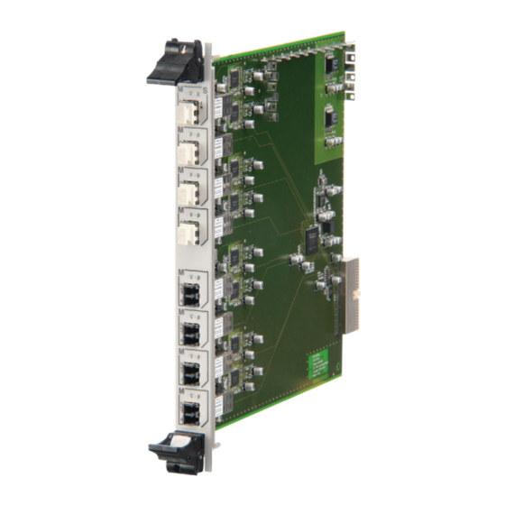
Page 14: Master/Slave Board
Master/Slave board The Master/Slave board is easily inserted into the GEN series mainframe and is automatically recognized by the Perception software. A Master/Slave board can be used as a master or slave. One board is required in the master mainframe and one board is required per slave mainframe. - Page 15 ® Figure 2-2: Example of a duplex LC connector LED indicators On the front panel of the Master/Slave board two LEDs indicate the status of the link. icon is used to identify the signal detect function. icon is for data/synchronization identification. Figure 2-3: LED indicators icon icon...
- Page 16 In the GEN series tower model the Master/Slave board is installed on the left-hand side of the system controller board. Figure 2-4: GEN series tower model with Master/Slave board installed Master/Slave board System controller board I2710-1.0 en...
- Page 17 In the GEN series 19” rack model the Master/Slave board is installed into Slot A on the right- hand side of the system controller board. Figure 2-5: GEN series 19” rack model with Master/Slave board installed System controller board Master/Slave board (Slot A) Note With a Master/Slave board installed the GEN series 19”...
-
Page 18: Installation
Installation Installing and removing the Master/Slave board The Master/Slave board is easily inserted into the GEN series mainframe and is automatically recognized by the Perception software. The board is removed and installed in the same way as all the acquisition boards. - Page 19 Installing the Master/Slave board To install the Master/Slave board proceed as follows: Shut down the GEN series and remove the power input cable. Ensure that the ejector levers are in the outermost position, tilting away from the board. Slide the board into its guide rails until the ejectors contact the perforated metal strips at top and bottom.
- Page 20 Press both ejectors inwards to seat the board. They act as levers to gently push the board into its backplane sockets. Figure 2-7: Press ejectors inwards Fasten the small set screw on both ejectors on the board. Figure 2-8: Ejector set screw The Master/Slave board is installed.
- Page 21 Removing the Master/Slave board To remove the Master/Slave board: Shut down the GEN series and remove the power input cable. Loosen the small set screw on both ejectors on the board. Figure 2-9: Ejector set screw Press the inner grey button on each ejector to release the catch.
- Page 22 Press both ejectors outwards to release the board. They act as levers to gently pull the board from its backplane sockets. Figure 2-11: Press ejectors outwards I2710-1.0 en...
- Page 23 Slide the board out of the GEN series unit. Figure 2-12: Remove the board I2710-1.0 en...
-
Page 24: Connecting The Master/Slave Board
2.2.2 Connecting the Master/Slave board With the fiber-optic cable, connect the Master/Slave board labelled M, OUT of the master mainframe to the top connector labelled M/S IN of the Master/Slave board of the slave mainframes. Figure 2-13: Connecting the Master/Slave Master mainframe (M, OUT) Slave mainframe (M/S IN) Fiber-optic cable... -
Page 25: Example Of A Master/Slave Configuration
2.2.3 Example of a Master/Slave configuration The following diagram shows an example of a Master/Slave configuration with a master driving four slave mainframes. Figure 2-14: Example of a Master/Slave configuration with four slave mainframes Master mainframe Slave mainframes Fiber-optic cable Connect the Master/Slave board connector labelled M/S, OUT 1 of the master mainframe to the top connector labelled M/S IN of the Master/Slave board of the first slave mainframe. -
Page 26: Setting The Master/Slave Operating Modes
2.2.4 Setting the Master/Slave operating modes A Master/Slave board can be used as a master or slave. After installation of the Master/Slave board into the mainframe, set the operating modes in the Perception software. In the Perception work area: Figure 2-15: Perception work area with Master/Slave Settings tab General group Master/Slave mode column... - Page 27 The Master/Slave operating mode of the mainframe has been set. If you have set the mainframe to Master mode, the letter "M" appears in the GEN series front panel. Figure 2-16: Mainframe in Master mode If you have set the mainframe to Slave mode, the letter "S" appears in the GEN series front panel.
-
Page 28: Setting The Master/Slave Trigger
2.2.5 Setting the Master/Slave trigger When the Master/Slave board is in use, a recorder can either put the recorder trigger on the Master/Slave trigger line and/or pick up the trigger from the Master/Slave trigger line. There are four settings that can be selected in the Perception software: Disabled No trigger transmitted to or received from other mainframes Transmit... - Page 29 Figure 2-19: Perception work area with Master/Slave trigger Settings tab Trigger group Master/Slave trigger column To set the Master/Slave trigger in the Perception software, proceed as follows: If it is not already active, start Perception. Make sure that you are connected to the required mainframes. Use the Hardware Navigator to do this.
-
Page 30: Setting The Synchronization Source (Sync Source)
2.2.6 Setting the synchronization source (Sync source) Depending on the selected synchronization source the date and time are controlled by either the PC (RTC), or an installed IRIG (IRIG) or IRIG/GPS (GPS) board. The source is selected in the Perception software. In the Perception work area: Figure 2-21: Perception work area synchronization source Settings tab... -
Page 31: Verification
Verification Initial check-out For an initial check-out of your Master/Slave configuration, verify as follows: Is the mainframe installed properly: fuses, power selection, power cord connected? Is the Master/Slave board installed properly? Is the fiber-optic cable between the Master/Slave boards in the mainframes connected properly? Has the Master/Slave operating mode of the mainframe been set in the Perception software? -
Page 32: Verification Procedure
3.2.1 Hardware set-up Set-up two GEN series mainframes with each a Master/Slave board installed and with each at least one recorder board installed. Connect a TTL level, 1 Hertz signal to the top input of the first recorder board of the master mainframe and to the top input of the first recorder board of the slave mainframe. - Page 33 In the Settings sheet, go to the Trigger group in the task pane and select Channel. 10 In the Trigger mode column, set all triggers to Off. Figure 3-3: Trigger mode list 11 Select the input with the connected TTL level, 1 Hertz signal on the master mainframe and set the trigger of this channel to Basic.
-
Page 34: Making A Multi-Mainframe Recording
3.2.3 Making a multi-mainframe recording Wait for the “MASTER SLAVE” status to display Synchronized before proceeding to the next step. Figure 3-5: MASTER SLAVE Synchronized Press Run in the acquisition control panel to start a recording. The signal on the master mainframe will now generate a trigger event. This trigger event will be relayed to the slave mainframe. -
Page 35: Specifications
Specifications Introduction This chapter contains information about: Master/Slave board specifications Fiber-optic cable specifications I2710-1.0 en... -
Page 36: Master/Slave Board Specifications
Master/Slave board specifications Master/Slave board Outputs 8, one master mainframe can drive up to eight slave main- frames Inputs 1, combined with master output Master/Slave configuration Star: one master mainframe can drive up to eight slave main- frames in a star configuration. No daisy-chaining Cabling Fiber-optic Connectors... -
Page 37: Fiber-Optic Cable Specifications
Fiber-optic cable specifications Fiber-optic cable Connector ® Duplex Transfer rate 2 Gbit/s Wavelength 850 nm Cable type Multimode 50/125 μm Dynamic range + 9 dB Isolation Ω/meter Cable length 10 m 20 m Maximum length 300 m using a single cable Maximum length will decrease by 100 m for each patch panel installed I2710-1.0 en... - Page 38 Index Specifications ..........36 Master/Slave configuration, example ....25 Board calibration ..........18 Master/Slave option Deliverables ...........13 Fiber-optic cable ........12, 13 Fiber-optic cable connection ......24 Calibration (system) ...........18 Master mode ..........12 Connecting Master/Slave board ......12, 13, 14 Fiber-optic cable ..........24 Master/Slave trigger ........28 Master/Slave board ........24 Operating modes ...........12 Operating modes, settings ......26...
- Page 39 Verification Initial check-out ..........31 Verification procedure ........32 Verification procedure ........32 Hardware set-up ..........32 Multi-mainframe recording ......34 Software set-up ..........32 I2710-1.0 en - Index...
- Page 42 Sales Office LDS Test and Measurement SARL 9 Avenue du Canada, Les Ulis BP 221 91942 Courtaboeuf Cedex Tel: +33 (0)1 64 86 45 45 . Email: info@hbm.com Germany Sales Office LDS Test and Measurement GmbH Carl-Zeiss-Ring 11-13 . 85737 Ismaning Tel: +49 89 92 33 33 0 .
Need help?
Do you have a question about the GEN Series and is the answer not in the manual?
Questions and answers