Sign In
Upload
Manuals
Brands
HBM Manuals
Measuring Instruments
Genesis GEN5i
HBM Genesis GEN5i Manuals
Manuals and User Guides for HBM Genesis GEN5i. We have
1
HBM Genesis GEN5i manual available for free PDF download: User Manual
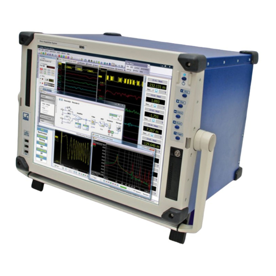
HBM Genesis GEN5i User Manual (598 pages)
Portable, Integrated Data Acquisition System
Brand:
HBM
| Category:
Measuring Instruments
| Size: 21 MB
Table of Contents
Table of Contents
5
About this Manual
14
Symbols Used in this Manual
14
Manual Conventions
15
Safety Messages
16
Introduction
16
FCC and General
19
Grounding
20
Instrument Symbols
22
Protection and Isolation
23
Measurement Categories
23
Categories According to IEC 61010-2-030:2010
23
Protection
25
Overvoltage/Current Protection
26
Isolation
26
Environment
27
Laser Safety
28
Manual Handling of Loads
29
International Safety Warnings
30
Operation of Electrical Installations
46
Normative Documents and Declarations
47
Electrical
47
Electro Static Discharge (ESD)
47
Electro-Magnetic Compatibility (EMC)
48
Environment
50
WEEE - Waste Electrical and Electronical Equipment
50
Packaging
50
Environmental Protection
50
Declaration of Conformity
51
Batteries
52
General
52
Remove and Replace
53
Recharge
54
Dispose
55
Mains Power
56
Power and Frequency Requirements
56
Connecting Power
57
Fuse Requirements and Protection
58
Fuse Replacement
59
Introduction
60
Introducing the Gen5I
60
Mainframe Overview
61
Hardware
62
Backplane
62
Interface/Controller Module
62
Input Cards
62
Master/Slave Card
63
Thermal Protection
63
Module and Card Slot Placement
65
Acquisition
66
Statstream
66
Signal Conditioning
68
Data Storage
69
PC Section
70
Disk Option
72
RAID 0 Technology
72
Gen5I Removable Disk
74
Gen5I System and Data Disk
75
Gen5I Hard Disk and Solid State Disk Technology
76
Perception Software
77
Perception Language Setting
80
Set up Your Gen5I
83
PC Connections
83
PC Plug-In Cards
85
Installing Plug-In Cards
86
Removing and Installing Acquisiton Modules
89
Removing Modules
89
Installing Modules
90
Protective Cover
92
Removing Protective Cover and Accessories Box
92
Opening Accessories Box
93
Closing Accessories Box
94
Installing Protective Cover
94
Handle
95
Turning Handle
95
Feet
98
Turning Feet out
98
Turning Feet in
99
Getting Started
100
Front Panel Control
100
Getting Started
105
Network Interfacing
106
Wireless Network
108
Acquisition and Storage
110
Introduction
110
Acquisition
111
Storage
112
More on Sweeps
113
Pre-Trigger Sweeps
114
More on Continuous Data Storage
116
Time Base
118
Real-Time Sampling and Time Base
118
Time Base Settings for Fft's
119
Additional Information
120
10 Digital Trigger Modes
122
Introduction
122
Understanding Digital Triggering
123
Digital Trigger Detector
123
Valid Trigger Conditions
125
Trigger Modes
127
Basic Trigger Mode
127
Dual Trigger Mode
128
Window Trigger Mode
129
Dual-Window Trigger Mode
130
Sequential Trigger Mode
131
Trigger Qualifier
132
Trigger Add-Ons
133
Slope Detector
133
Pulse Detector
134
Holdoff
135
Interval Timer
136
Interval Timer - Less
136
Interval Timer - more
137
Interval Timer - between
138
Interval Timer - Notbetween
139
Event Counter
140
Recorder and System Trigger
141
Channel Alarm
143
11 Interface/Controller Module
144
Introduction
144
Interface/Controller Module 2 (IM2)
145
IM2 - Communication and Control
146
Using the 1 Gbit Option Connections
147
IM2 - Master/Slave Synchronization
147
IM2 - I/O Connectors
148
IM2 - Expansion Slot
149
IM2 - Iscsi Based Storage
150
Introduction: Iscsi NAS with GEN DAQ Network
151
TCP/IP Connection with an NAS
152
External Storage Setup Dialog - Perception
153
GEN Data Acquisition System
153
Iscsi Host
154
Iscsi Target
154
Target Name (IQN)
155
What Is CHAP
155
How to Format the Iscsi
156
11.3.10 Status Messages/ Troubleshooting
157
11.3.11 Setup an Iscsi NAS Connected Across an Ethernet Switch
159
11.3.12 Setup an Iscsi NAS Connected Without an Ethernet Switch
163
11.3.13 Setup an Iscsi NAS Connected to a Corporate Network - Basic Setup
167
11.3.14 Setup an Iscsi NAS Connected to a Corporate Network - Advanced Setup
172
IM1 - Interface/Controller Module
177
IM1 - Communication and Control - Standard Ethernet Interface
178
IM1 - I/O Connectors
178
IM1 - Expansion Slot
179
IM2 - Interface/Controller Module Options
180
Option - Solid State Disk (SSD)
180
Option - Optical 1 Gbit Ethernet Interface
181
Cable Selection and Lengths
182
Option - 10 Gbit Ethernet Interface
182
Connections and Using the 10 Gbit Option
183
Front Panel Layout
184
10 Gbit Ethernet Option Accessories
184
Cable Selection and Lengths
185
10 Gbit Ethernet Card in GENDAQ Series Networks
186
Connecting the 10 Gbit Ethernet Option to a PC
186
Network Interface Selection in Perception
187
Important Note Windows® 7 - Optimum Settings
188
Installation of 1 Gbit SFP/10 Gbit SFP+ Module
189
Introduction
189
Warnings
189
Installation Steps
191
Optical Network (SFP) - Trouble Shooting
194
Removing Protective Cover on Gen2I and Gen5I
195
Option - IRIG and IRIG/GPS Time Synchronization
196
GPS Antenna System Rules
197
Rule 1. Antenna Placement
198
Rule 2. Is a GPS Line Amplifier Needed
198
Rule 3: Lightning Arrestors
198
Rule 4: Interconnect Cables
199
IM1 - Interface/Controller Module 1 Options
200
Option - Fiber Optic Ethernet Interface
200
Auto Detection
201
Front-Panel Layout
202
Connection
203
Option - SCSI Interface Board
206
Option - IRIG and IRIG/GPS Time Synchronization
208
GPS Antenna System Rules
209
Master/Slave Card
212
Master/Slave Card Operations
213
LED Indicators
215
Installation
218
Installing and Removing the Master/Slave Card
218
Connecting the Master/Slave Card
226
Example of a Master/Slave Configuration
227
Setting the Master/Slave Operating Modes
229
Setting the Master/Slave Trigger
232
Setting the Synchronization Source (Sync Source)
235
Verification Procedure
236
Hardware Set-Up
236
Software Set-Up
236
Making a Multi-Mainframe Recording
238
12 Input Cards
239
Available Input Cards
239
Isolated 1Kv Input Cards
244
GN610, Isolated 1Kv 2Ms/S Input Card
244
GN611, Isolated 1 Kv 200Ks/S Input Card
246
Using the GN610 and GN611
247
Understanding the GN610 and GN611 Category Rating
250
Understanding the GN610 and GN611 Input
251
GN610 and GN611 Input Overload Protection
253
Thermal Monitor of the Input Channels
254
Thermal Shutdown in Critical Conditions
255
Automatic Restore of User Selected Range
256
Basic Amplifier None Isolated Input Cards
258
GN810 Basic 200K Input Card
258
GN811 Basic 1M Input Card
259
GN812 Basic 1M Isolated Input Card
260
Basic Extended Isolated Amplifier Card
261
GN813 Basic XT ISO 1 Ms/S Input Card
261
GN814 Basic XT ISO 200K Input Card
263
GN410 and GN411 Bridge Input Cards
264
Bridge Amplifier Configuration
265
Input Connectors
267
Bridge Completion
267
Shunt Calibration
267
Shielding and Driven Guard
268
Various Bridge Configurations
269
Bridge Connector Reference Card
271
Configuring and Using the Bridge Amplifier
272
Bridge Completion
273
Bridge Completion - Full (4/4) Bridge
273
Bridge Completion - Half (1/2 or 2/4) Bridge
275
Bridge Completion - Quarter (1/4) Bridge
277
Excitation
279
Shunt Verification - Setup
283
Shunt Verification - Procedure
285
Bridge Balance
287
GN440 and GN441 Universal Amplifier Input Cards
289
GN412 and GN413 High Speed - Differential Input Cards
290
High Channel Count Basic Input Cards
291
GN1610 and GN3210 IEPE and Charge 250 Ks/S Input Cards
291
GN1611 and GN3211 Basic 20 Ks/S Input Cards
293
GN401 Optical Fiber Isolated 100 Ms/S Input Card
295
Binary Marker Cards
296
12.11.1 GN6470 Binary Marker Card
296
12.11.2 GN4070 Binary Marker HV Card
297
12.11.3 Connector Pinning GN6470 and GN4070
298
12.11.4 GN6470 and GN4070 Counter Mode Pinning
299
12.11.5 GN6470 and GN4070 Frequency (RPM) Mode Pinning
300
12.11.6 GN6470 and GN4070 Quadrature (Position) Mode Pinning
301
12.11.7 GN4070 Connectors and Pinning
303
5B Integration Card Specifications
310
A Specifications
312
B3723-1.0 en (GEN Series Gen5I Portable Data Recorder)
312
B2629-2.0 en (GEN Series GN401)
331
B3248-1.0 en (GEN Series GN412 and GN413)
353
B3618-3.0 en (GEN Series GN610)
356
B3716-2.0 en (GEN Series GN611)
381
B2632-3.0 en (GEN Series GN810)
403
B2640-3.0 en (GEN Series GN811)
416
B2634-3.0 en (GEN Series GN812)
430
B2635-4.0 en (GEN Series GN813)
444
B2889-5.0 en (GEN Series GN814)
458
B3244-1.0 en (GEN Series GN410 and GN411)
472
B3250-1.0 en (GEN Series GN440 and GN441)
476
B3240-2.0 en (GEN Series GN1610 and GN3210)
479
B3264-2.0 en (GEN Series GN1611 and GN3211)
487
B3246-1.0 en (GEN Series GN4070)
492
B3245-1.0 en (GEN Series GN6470)
496
B Maintenance
499
Preventive Maintenance
499
Hard Disk Maintenance
499
Solid State Disk Maintenance
500
Cleaning
501
C Service Information
502
General - Service Information
502
Calibration/Verification
503
D Understanding Inputs and Usage of Probes
504
Overview of Inputs
504
Overview of Probes
513
Voltage Probes for Single-Ended Amplifiers
514
Voltage Probes for ISOLATED Amplifiers
516
Voltage Probes for Isolated Amplifiers (High Accuracy)
518
Passive Differential Voltage Probes
520
Active Differential Voltage Probes
522
Reference Tables
523
Amplifiers and Probes Match Overview Table
523
Amplifier/Probe Matrix
525
HBM/LDS Part Number Reference Table
525
Probe Accessories
526
General on Probes
528
Probes
529
Probes
531
Probes and Differential Measurements
532
Shunt Measurements
533
E Trouble Shooting
534
Restoring the Gen5I
534
Language Setting Windows 7 Ultimate
542
Install Language Pack in Windows 7® Ultimate
544
F Rack Mount Instructions
547
Mount Gen5I in a 19-Inch Rack
547
G Application Specific Usage
551
Rotational External Clock
551
GEN DAQ Settings Explained
551
Memory and Time Base
553
Mainframe
553
Recorder/Time Base Groups
555
External Clock Divider
555
Calculating Sample Limits for External Time Base Use
555
Calculation Example
555
Perception Display Settings Explained
556
Cylinder Pressure Analysis Option Package
558
Cylinder Pressure Analysis Customer Evaluation
558
Cylinder Pressure Analysis and TDC Settings
559
Dy/Dt Triggering
560
H Using Fiber Optic Cables
564
Calculating Maximum Fiber Cable Length
564
I 10 GB Ethernet Windows Settings
566
Introduction
566
J Setting up the Iscsi with Synology NAS
574
Introduction
574
KBE3200 USB to Optical RS232 Convertor
588
Re-Programming of the USB-RS232 (Opt. 650Nm) Converter to Work with BE3200
588
Advertisement
Advertisement
Related Products
HBM Genesis series
HBM GEN series
HBM GN610
HBM GN611
HBM GEN3i
HBM GK7000
HBM GK7600
HBM Genesis ISOBE5600
HBM BU18
HBM C15
HBM Categories
Transducer
Measuring Instruments
Amplifier
Accessories
Industrial Equipment
More HBM Manuals
Login
Sign In
OR
Sign in with Facebook
Sign in with Google
Upload manual
Upload from disk
Upload from URL