Table of Contents
Advertisement
Quick Links
Advertisement
Table of Contents
Troubleshooting

Related Manuals for ABB Robotics OmniCore C90XT


Summary of Contents for ABB Robotics OmniCore C90XT
- Page 1 ROBOTICS Product manual OmniCore C90XT...
- Page 2 Trace back information: Workspace 21B version a6 Checked in 2021-05-31 Skribenta version 5.4.005...
- Page 3 Product manual OmniCore C90XT OmniCore Document ID: 3HAC073706-001 Revision: E © Copyright 2020-2021 ABB. All rights reserved. Specifications subject to change without notice.
- Page 4 The information in this manual is subject to change without notice and should not be construed as a commitment by ABB. ABB assumes no responsibility for any errors that may appear in this manual. Except as may be expressly stated anywhere in this manual, nothing herein shall be construed as any kind of guarantee or warranty by ABB for losses, damage to persons or property, fitness for a specific purpose or the like.
-
Page 5: Table Of Contents
Maintenance and repair ..................Troubleshooting ....................Decommissioning ....................Controller description OmniCore C90XT ....................Technical data for OmniCore C90XT controller ............The unit is sensitive to ESD ................. Handling of FlexPendant ..................Network security ....................Open source and 3rd party components in RobotWare .......... - Page 6 5.2.11 Replacing the drive unit ................5.2.12 Replacing the fieldbus master ..............5.2.13 Replacing the conveyor tracking module(CTM) ..........5.2.14 Replacing the air filter ................Product manual - OmniCore C90XT 3HAC073706-001 Revision: E © Copyright 2020-2021 ABB. All rights reserved.
- Page 7 Standard toolkit for controller ................Screw joints ..................... Weight specifications ..................Lifting accessories and lifting instructions .............. Spare parts Controller parts ....................FlexPendant parts ..................... Product manual - OmniCore C90XT 3HAC073706-001 Revision: E © Copyright 2020-2021 ABB. All rights reserved.
- Page 8 Table of contents Manipulator cables .................... 9.3.1 Manipulator cables .................. 9.3.2 Customer cables - CP/CS connectors (option) ..........9.3.3 Customer cables - Ethernet floor cable ............Index Product manual - OmniCore C90XT 3HAC073706-001 Revision: E © Copyright 2020-2021 ABB. All rights reserved.
-
Page 9: Overview Of This Manual
References Document name Document ID Product specification - OmniCore C line 3HAC065034-001 Circuit diagram - OmniCore C90XT 3HAC065464-009 Operating manual - RobotStudio 3HAC032104-001 Operating manual - OmniCore 3HAC065036-001 Operating manual - Integrator's guide OmniCore... - Page 10 Configuring safety stops on page 102. • Updated FlexPendant holder assembling procedure. • Updated information about safety data. • Updated images related to general stop. Product manual - OmniCore C90XT 3HAC073706-001 Revision: E © Copyright 2020-2021 ABB. All rights reserved.
-
Page 11: Product Documentation
Product documentation Categories for user documentation from ABB Robotics The user documentation from ABB Robotics is divided into a number of categories. This listing is based on the type of information in the documents, regardless of whether the products are standard or optional. - Page 12 The operating manuals describe hands-on handling of the products. The manuals are aimed at those having first-hand operational contact with the product, that is production cell operators, programmers, and troubleshooters. Product manual - OmniCore C90XT 3HAC073706-001 Revision: E © Copyright 2020-2021 ABB. All rights reserved.
-
Page 13: Safety
ABB is not liable for damages caused by the use of non-original spare parts and equipment. Product manual - OmniCore C90XT 3HAC073706-001 Revision: E © Copyright 2020-2021 ABB. All rights reserved. -
Page 14: Safety Data
Extended Safety Functions. The Extended Safety Functions is an option. Performance level for OmniCore C90XT The following performance level data is applicable for OmniCore C90XT together with all supported ABB manipulators The OmniCore C90XT provides safety with structure category 3 with performance level d according to EN ISO 13849-1. - Page 15 Tool Orientation Supervision (TOR) (category 4.29E-08 0 stop/category 1 stop) Control Error Supervision 4.29E-08 The supported manipulators are listed in Product specification - OmniCore C line. Product manual - OmniCore C90XT 3HAC073706-001 Revision: E © Copyright 2020-2021 ABB. All rights reserved.
-
Page 16: Requirements On Personnel
The plant liable must make sure that the personnel is trained on the robot, and on responding to emergency or abnormal situations. Personal protective equipment Use personal protective equipment, as stated in the instructions. Product manual - OmniCore C90XT 3HAC073706-001 Revision: E © Copyright 2020-2021 ABB. All rights reserved. -
Page 17: Safety Signals And Symbols
NOTE Signal word used to indicate important facts and conditions. Continues on next page Product manual - OmniCore C90XT 3HAC073706-001 Revision: E © Copyright 2020-2021 ABB. All rights reserved. - Page 18 1.2.1 Safety signals in the manual Continued Symbol Designation Significance Signal word used to indicate where to find additional information or how to do an operation in an easier way. Product manual - OmniCore C90XT 3HAC073706-001 Revision: E © Copyright 2020-2021 ABB. All rights reserved.
-
Page 19: Safety Symbols On Controller Labels
Symbols on safety labels Label Description Read the user manual before use. xx1400001152 The robot is delivered to start in automatic mode xx2100000104 Continues on next page Product manual - OmniCore C90XT 3HAC073706-001 Revision: E © Copyright 2020-2021 ABB. All rights reserved. - Page 20 Safety UL label (for the Functional Safety solution together with UL mark). xx1700000353 SafeMove label (for SafeMove Basic and SafeMove Pro soft- ware). xx1700000355 Rating label (example) xx1900001805 Continues on next page Product manual - OmniCore C90XT 3HAC073706-001 Revision: E © Copyright 2020-2021 ABB. All rights reserved.
- Page 21 High voltage inside the module even if the main switch is in the OFF position. xx1400001156 ESD sensitive components inside the controller. xx1400001162 Product manual - OmniCore C90XT 3HAC073706-001 Revision: E © Copyright 2020-2021 ABB. All rights reserved.
-
Page 22: Robot Stopping Functions
The default configuration is stop category 1. Note For OmniCore, a safety input that is initiated must remain active for at least 100 Continues on next page Product manual - OmniCore C90XT 3HAC073706-001 Revision: E © Copyright 2020-2021 ABB. All rights reserved. - Page 23 In RobotWare 7.0 there are two values for the safety input Emergency Stop, named Category1EES (for external emergency stop) and Category1LES (for emergency stop on FlexPendant). These are merged in RobotWare 7.1 into Category1ES. Product manual - OmniCore C90XT 3HAC073706-001 Revision: E © Copyright 2020-2021 ABB. All rights reserved.
-
Page 24: About Emergency Stops
2 Locate and reset the device or devices that initiated the emergency stop condition. 3 Press the Motors On button to recover from the emergency stop condition. Use the FlexPendant or Robot Control Mate. Product manual - OmniCore C90XT 3HAC073706-001 Revision: E © Copyright 2020-2021 ABB. All rights reserved. -
Page 25: Enabling Device And Hold-To-Run Functionality
How to use the hold-to-run function for manual full speed mode is described in the operating manual for the controller. Note The manual full speed mode is not available in all markets. Product manual - OmniCore C90XT 3HAC073706-001 Revision: E © Copyright 2020-2021 ABB. All rights reserved. -
Page 26: Robot Operating Modes
250 mm/s. This is achieved by limiting the speed to 3% of the programmed speed. Through manual control the speed can be increased up to 100% of the programmed speed. Continues on next page Product manual - OmniCore C90XT 3HAC073706-001 Revision: E © Copyright 2020-2021 ABB. All rights reserved. - Page 27 Starting and stopping program execution for program verification • Stepping program execution • Setting speed (0–100%) • Setting program pointer (to Main, to routine, to cursor, to service routine, etc. Product manual - OmniCore C90XT 3HAC073706-001 Revision: E © Copyright 2020-2021 ABB. All rights reserved.
-
Page 28: About The Automatic Mode
See the integrator's documentation for the machinery/robot system for details on which tasks are to be performed in automatic mode. Safeguard mechanisms • Protective stop through Automatic Stop, AS Product manual - OmniCore C90XT 3HAC073706-001 Revision: E © Copyright 2020-2021 ABB. All rights reserved. -
Page 29: Installation And Commissioning
When the robot is installed at a height, hanging, or other than mounted directly on the floor, there will be additional hazards. Continues on next page Product manual - OmniCore C90XT 3HAC073706-001 Revision: E © Copyright 2020-2021 ABB. All rights reserved. - Page 30 The risk assessment should also consider other hazards arising from the application, such as, but not limited to: • Water • Compressed air • Hydraulics Continues on next page Product manual - OmniCore C90XT 3HAC073706-001 Revision: E © Copyright 2020-2021 ABB. All rights reserved.
- Page 31 Before the robot system is put into operation, verify that the safety functions are working as intended and that any remaining hazards identified in the risk assessment are mitigated to an acceptable level. Product manual - OmniCore C90XT 3HAC073706-001 Revision: E © Copyright 2020-2021 ABB. All rights reserved.
-
Page 32: Operation
These must be stored out of reach and sight so that they cannot be mistaken for being in use. Product manual - OmniCore C90XT 3HAC073706-001 Revision: E © Copyright 2020-2021 ABB. All rights reserved. -
Page 33: Maintenance And Repair
See safety instructions for the batteries in Material/product safety data sheet - Battery pack (3HAC043118-001). Related information See also the safety information related to installation and operation. Product manual - OmniCore C90XT 3HAC073706-001 Revision: E © Copyright 2020-2021 ABB. All rights reserved. -
Page 34: Troubleshooting
A risk assessment must be done to address both robot and robot system specific hazards. Related information See also the safety information related to installation, operation, maintenance, and repair. Product manual - OmniCore C90XT 3HAC073706-001 Revision: E © Copyright 2020-2021 ABB. All rights reserved. -
Page 35: Decommissioning
1 Safety 1.9 Decommissioning 1.9 Decommissioning General See section Decommissioning on page 357. Product manual - OmniCore C90XT 3HAC073706-001 Revision: E © Copyright 2020-2021 ABB. All rights reserved. - Page 36 This page is intentionally left blank...
-
Page 37: Controller Description
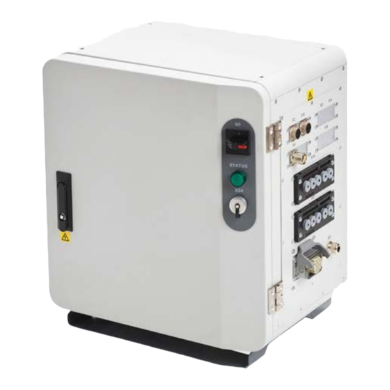
2 Controller description 2.1 OmniCore C90XT About OmniCore C90XT The OmniCore C90XT is one of OmniCore C line compact controllers. The OmniCore C90XT controller offers a compact solution suitable for most applications with room for some additional equipment inside. It is used to control an ABB manipulator used in industrial applications such as material handling and machine tending. -
Page 38: Technical Data For Omnicore C90Xt Controller
2 Controller description 2.2 Technical data for OmniCore C90XT controller 2.2 Technical data for OmniCore C90XT controller Overview of the controller The OmniCore C90XT controller has all components in one cabinet. xx1900001447 Reference OmniCore C90XT to circuit diagram Basic box... - Page 39 2 Controller description 2.2 Technical data for OmniCore C90XT controller Continued Reference OmniCore C90XT to circuit diagram Ethernet switch Option Standard fan Baseline Heat exchanger Baseline Axis computer Baseline Main computer Baseline Power supply Baseline Power supply Option ODVA power supply...
- Page 40 2 Controller description 2.2 Technical data for OmniCore C90XT controller Continued Transportation and storage conditions Parameter Value Minimum ambient temperature -25°C (-13°F) Maximum ambient temperature +55°C (+131°F) Maximum ambient temperature (less than 24 +70°C (+158°F) hrs) Maximum ambient humidity Maximum 95% at constant temperature.
- Page 41 Line fusing There is no integrated fuse inside the OmniCore C90XT controller. Add an external fuse (time-delay) or circuit breaker (class K) according to full load current, as marked on the controller nameplate. The following table shows the recommended rating for an external fuse or circuit breaker.
- Page 42 2 Controller description 2.2 Technical data for OmniCore C90XT controller Continued Wrist strap button The location of the wrist strap button is shown in the following illustration. xx1900001446 There is an additional wrist strap button on the main computer. Product manual - OmniCore C90XT 3HAC073706-001 Revision: E ©...
-
Page 43: The Unit Is Sensitive To Esd
The mat must be grounded through a current-limiting resistor. • Use a dissipative table mat. The mat should provide a controlled discharge of static voltages and must be grounded. Product manual - OmniCore C90XT 3HAC073706-001 Revision: E © Copyright 2020-2021 ABB. All rights reserved. -
Page 44: Handling Of Flexpendant
Any means of connecting the FlexPendant with other than the supplied cable and its standard connector must not render the emergency stop button inoperative. Continues on next page Product manual - OmniCore C90XT 3HAC073706-001 Revision: E © Copyright 2020-2021 ABB. All rights reserved. - Page 45 2 Controller description 2.4 Handling of FlexPendant Continued Always test the emergency stop button to make sure it works if a custom connection cable is used. Product manual - OmniCore C90XT 3HAC073706-001 Revision: E © Copyright 2020-2021 ABB. All rights reserved.
-
Page 46: Network Security
Ltd and its entities are not liable for damage and/or loss related to such security breaches, any unauthorized access, interference, intrusion, leakage and/or theft of data or information. Product manual - OmniCore C90XT 3HAC073706-001 Revision: E © Copyright 2020-2021 ABB. All rights reserved. -
Page 47: Open Source And 3Rd Party Components In Robotware
For the CTM application, a list of copyright statements and licenses is available in the file /opt/ABB.com/ctm/licenses.txt located on the CTM board and accessible via the console port or by downloading the file over SFTP. Product manual - OmniCore C90XT 3HAC073706-001 Revision: E © Copyright 2020-2021 ABB. All rights reserved. -
Page 48: Abb Ability
Rights) are exclusively owned by us. In addition, we have the right to use the data for benchmarking purposes if and to the extent it is anonymized or non-confidential. Continues on next page Product manual - OmniCore C90XT 3HAC073706-001 Revision: E © Copyright 2020-2021 ABB. All rights reserved. - Page 49 ABB Ability™ General Terms and Conditions. ABB Ability™ Terms and Conditions: https://ability.abb.com/terms Special Terms and Conditions for ABB Ability™ Connected Services: https://new.abb.com/products/robotics/service/robot-registration Product manual - OmniCore C90XT 3HAC073706-001 Revision: E © Copyright 2020-2021 ABB. All rights reserved.
- Page 50 This page is intentionally left blank...
-
Page 51: Installation And Commissioning
Note If the OmniCore C90XT is connected to power, always make sure that the robot is connected to protective earth and a residual current device (RCD) before starting any installation work. Product manual - OmniCore C90XT 3HAC073706-001 Revision: E ©... -
Page 52: Installation Activities
Install options and add-ons (optional). Installing options on page 111. Installing add-on devices on page 151. Initial test before commissioning. Initial test before commissioning on page 160. Product manual - OmniCore C90XT 3HAC073706-001 Revision: E © Copyright 2020-2021 ABB. All rights reserved. -
Page 53: Transporting And Handling
The weight of the controller module is detailed in section Weight on page ° 0 xx1900001445 Note After removing the lifting lock, tighten the plastic screws (Torque: 0.8 Nm-1 Nm) for the controller cabinet. Product manual - OmniCore C90XT 3HAC073706-001 Revision: E © Copyright 2020-2021 ABB. All rights reserved. -
Page 54: Unpacking
Operating conditions on page The controller can be taken to its installation site as described in section On-site in- stallation on page Product manual - OmniCore C90XT 3HAC073706-001 Revision: E © Copyright 2020-2021 ABB. All rights reserved. -
Page 55: Storing
3 Installation and commissioning 3.3.3 Storing 3.3.3 Storing Storing the controller For storing, see Transportation and storage conditions on page Product manual - OmniCore C90XT 3HAC073706-001 Revision: E © Copyright 2020-2021 ABB. All rights reserved. -
Page 56: On-Site Installation
The following illustration shows the dimensions between the feet of the OmniCore C90XT controller, as seen from below. Continues on next page Product manual - OmniCore C90XT 3HAC073706-001 Revision: E © Copyright 2020-2021 ABB. All rights reserved. - Page 57 According to IEC60204-1, the power-operated switch should be installed between 600 mm to 1,900 mm above the servicing level. The switch will be easily accessible. Product manual - OmniCore C90XT 3HAC073706-001 Revision: E © Copyright 2020-2021 ABB. All rights reserved.
-
Page 58: Mounting The Flexpendant Holder
The FlexPendant should always be placed in the holder when it is not used and it is not allowed to use by unauthorized person. Continues on next page Product manual - OmniCore C90XT 3HAC073706-001 Revision: E © Copyright 2020-2021 ABB. All rights reserved. - Page 59 Use this procedure to mount the bracket for the emergency stop to the FlexPendant holder. Action Note/illustration Remove the four screws. Separate the rear part from the FlexPend- ant holder. xx2000002356 Continues on next page Product manual - OmniCore C90XT 3HAC073706-001 Revision: E © Copyright 2020-2021 ABB. All rights reserved.
- Page 60 Refit the rear part and secure with the Screws: BN33 Phillips pan head tapping screws. screw ST3.5x16 (4 pcs) Tightening torque: 9.4 Nm-12.2 Nm xx2000002356 Continues on next page Product manual - OmniCore C90XT 3HAC073706-001 Revision: E © Copyright 2020-2021 ABB. All rights reserved.
- Page 61 Use this procedure to hang the FlexPendant holder on any place where can hold the bracket, like the door of the controller. The bracket is included when the FlexPendant is purchased. Continues on next page Product manual - OmniCore C90XT 3HAC073706-001 Revision: E © Copyright 2020-2021 ABB. All rights reserved.
- Page 62 Remove the four screws. Separate the rear part from the FlexPend- ant holder. xx2000002356 Clean the surface and make sure it is dry. Continues on next page Product manual - OmniCore C90XT 3HAC073706-001 Revision: E © Copyright 2020-2021 ABB. All rights reserved.
- Page 63 Note/illustration Remove the protective liner from the tape. xx2000002357 Press the holder onto the desired place. Use two M5 screws to secure the holder. xx2000002358 Product manual - OmniCore C90XT 3HAC073706-001 Revision: E © Copyright 2020-2021 ABB. All rights reserved.
-
Page 64: Electrical Connections
CAUTION Always inspect the connector for dirt or damage before connecting it to the controller. Clean or replace any damaged parts. Connectors The following details the connection interface on the OmniCore C90XT controller. xx2000000338 Description Manipulator signal connector Cable grommet assembly (option) - Page 65 3 Installation and commissioning 3.5.1 Connectors on the OmniCore C90XT controller Continued Description TPU cover FlexPendant connection (TPU connector) ETH outlet connector Motors on lamp Power inlet switch Product manual - OmniCore C90XT 3HAC073706-001 Revision: E © Copyright 2020-2021 ABB. All rights reserved.
-
Page 66: Connecting Cables To The Controller
Shielded cable with twisted pair conductors. A specific cable signals should be used for field bus connections and Ethernet, according to the standard specification of the respective bus. Continues on next page Product manual - OmniCore C90XT 3HAC073706-001 Revision: E © Copyright 2020-2021 ABB. All rights reserved. - Page 67 If the grounding points have different electric potentials - grounding both ends will create a ground loop allowing unwanted current to flow in the shield. Continues on next page Product manual - OmniCore C90XT 3HAC073706-001 Revision: E © Copyright 2020-2021 ABB. All rights reserved.
- Page 68 Shield pigtail termination, as shown below, shall be avoided. If a pigtail connection cannot be avoided, make it as short as possible. xx1700001321 Continues on next page Product manual - OmniCore C90XT 3HAC073706-001 Revision: E © Copyright 2020-2021 ABB. All rights reserved.
- Page 69 The following figure shows 2 examples on how the ground and the signal cable screens can be connected: External unit Control cabinet Example 1 Example 2 xx1200000960 Continues on next page Product manual - OmniCore C90XT 3HAC073706-001 Revision: E © Copyright 2020-2021 ABB. All rights reserved.
- Page 70 V max voltage and 125 V nominal voltage. The resistor should be 100 Ω, and the capacitor should be 1W 0.1 - 1 µF (typically 0.47 µF). Product manual - OmniCore C90XT 3HAC073706-001 Revision: E © Copyright 2020-2021 ABB. All rights reserved.
-
Page 71: Connecting The Manipulator To The Controller
Connecting the cables from the manipulator to the controller Action Connect the manipulator cable to the connector X1. Lock the connector with the lever. Secure the cables to avoid tripping or wear. Product manual - OmniCore C90XT 3HAC073706-001 Revision: E © Copyright 2020-2021 ABB. All rights reserved. -
Page 72: Fitting The Connector
This section describes how to manufacture a cable for connecting the main power to the controller. xx1900001461 Detailed view xx1900001457 Description Female insert, quick lock Angle hood M20 Cable gland M20 Sealing screw Continues on next page Product manual - OmniCore C90XT 3HAC073706-001 Revision: E © Copyright 2020-2021 ABB. All rights reserved. - Page 73 For single phase: 1 Live (L) 2 Neutral (N) 3 Not used 4 Not used 5 Not used PE, Protective Earth, grounding Continues on next page Product manual - OmniCore C90XT 3HAC073706-001 Revision: E © Copyright 2020-2021 ABB. All rights reserved.
- Page 74 Push fine stranded wires into the Han- Quick Lock contact and push the slide with a screw driver until it comes to a stop. xx1900001459 Product manual - OmniCore C90XT 3HAC073706-001 Revision: E © Copyright 2020-2021 ABB. All rights reserved.
-
Page 75: Connecting Power Supply To And Grounding The Controller
Location of power supply connection xx1900001479 Location of grounding point Note The whole cabinet ground is connected to the X0.PE point. Continues on next page Product manual - OmniCore C90XT 3HAC073706-001 Revision: E © Copyright 2020-2021 ABB. All rights reserved. - Page 76 Circuit diagram - OmniCore C90XT, 3HAC065464-009 Line fusing There is no integrated fuse in side OmniCore C90XT controller. An external fuse or circuit breaker must be added by the integrator, according to the full load current rating. See Line fusing on page Connecting the power The following procedure describes how to connect the main power to the controller.
- Page 77 Connect the main power cable to the power inlet connector X0 and lock it by pressing the hook. When you hear a clear clicking sound, it is locked. xx1900001456 Product manual - OmniCore C90XT 3HAC073706-001 Revision: E © Copyright 2020-2021 ABB. All rights reserved.
-
Page 78: Connecting And Detaching A Flexpendant
1 On the status bar, tap the QuickSet button. 2 Tap the Logout/Restart tab. 3 In the FlexPendant section, tap Detach FlexPendant. Continues on next page Product manual - OmniCore C90XT 3HAC073706-001 Revision: E © Copyright 2020-2021 ABB. All rights reserved. - Page 79 A popup window with 30 seconds countdown timer is displayed. 5 When the countdown is progressing, loosen the locking ring and detach the FlexPendant from the controller. Continues on next page Product manual - OmniCore C90XT 3HAC073706-001 Revision: E © Copyright 2020-2021 ABB. All rights reserved.
- Page 80 Plug in the connector on the controller and tighten the locking ring. xx1900000975 CAUTION Make sure that the emergency stop button is not pressed in when connecting the FlexPendant. Product manual - OmniCore C90XT 3HAC073706-001 Revision: E © Copyright 2020-2021 ABB. All rights reserved.
-
Page 81: Network Connections On Omnicore
Connections on the OmniCore controller The following figure illustrates the available Ethernet port connectors on the controller. Note For information regarding location of the Ethernet port connectors, see Connectors on the OmniCore C90XT controller on page xx1800003138 Label Description I/O + LAN + ETHERNET Port to the robot's private network. - Page 82 Note The management port shall never be used for more than one client at a time. ABB Robotics assumes no responsibility for any errors/hazards that may appear when more than one client is attached to the management port. The LAN1, LAN2 and LAN3 ports are intended for connecting robot controller internal computers or network based process equipment to the controller, for example cameras, and welding equipment.
- Page 83 Robot Controller 1 Robot Controller 2 Private Public Private Public MGMT LAN1 LAN2 LAN3 MGMT LAN1 LAN2 LAN3 Private I/O xx1800003192 Continues on next page Product manual - OmniCore C90XT 3HAC073706-001 Revision: E © Copyright 2020-2021 ABB. All rights reserved.
- Page 84 IP address: The IP address for the OmniCore controller on the EtherNet network. Subnet mask: The subnet mask. Default gateway: The default gateway. xx2000000489 Continues on next page Product manual - OmniCore C90XT 3HAC073706-001 Revision: E © Copyright 2020-2021 ABB. All rights reserved.
- Page 85 Factory Network & Industrial Network PROFINET Robot Controller 1 Robot Controller 2 Private Public Private Public MGMT LAN1 LAN2 LAN3 MGMT LAN1 LAN2 LAN3 Camera xx1900001102 Product manual - OmniCore C90XT 3HAC073706-001 Revision: E © Copyright 2020-2021 ABB. All rights reserved.
-
Page 86: Set Up The Network Connection
B must be used to avoid any overlapping. Contact your local network administrator regarding network overlapping. See the section Communication in Technical reference manual - System parameters. Continues on next page Product manual - OmniCore C90XT 3HAC073706-001 Revision: E © Copyright 2020-2021 ABB. All rights reserved. - Page 87 See the section Communication in Technical reference manual - System parameters. Note For more information about connecting the Ability port to the internet, see Application manual - Controller software OmniCore. Continues on next page Product manual - OmniCore C90XT 3HAC073706-001 Revision: E © Copyright 2020-2021 ABB. All rights reserved.
- Page 88 For more information, see Technical reference manual - System parameters. Related information See more information about network configuration in Operating manual - Integrator's guide OmniCore. Product manual - OmniCore C90XT 3HAC073706-001 Revision: E © Copyright 2020-2021 ABB. All rights reserved.
-
Page 89: Descriptions For Connectors
This will affect the protection level of the cabinet if it's not executed correctly. It is recommended to use icotek KT grommet. Continues on next page Product manual - OmniCore C90XT 3HAC073706-001 Revision: E © Copyright 2020-2021 ABB. All rights reserved. - Page 90 If the process power supply is supplied by the logical power supply connector (X19), a surge protector must be installed to protect the device. Continues on next page Product manual - OmniCore C90XT 3HAC073706-001 Revision: E © Copyright 2020-2021 ABB. All rights reserved.
- Page 91 3 Installation and commissioning 3.5.9 Descriptions for connectors Continued For connection details, see Circuit diagram - OmniCore C90XT, 3HAC065464-009 and Application manual - Scalable I/O, 3HAC070208-001. Recommended surge protector xx1800002551 The protect voltage for the surge protector should be 24 V DC.
- Page 92 This will affect the protection level of the cabinet if it's not executed correctly. It is recommended to use icotek KT grommet. Continues on next page Product manual - OmniCore C90XT 3HAC073706-001 Revision: E © Copyright 2020-2021 ABB. All rights reserved.
- Page 93 The 24 V terminal block power supply is isolated from the internal logical circuit of the controller. For connection details, see Circuit diagram - OmniCore C90XT, 3HAC065464-009. Customer cable layout It is recommended to use multicore cable for the customer connection.
- Page 94 Type Weidmüller S2L 3.50 90F S2L 3.50/16/90F 3.5SN BK BX 2*8 pins Article number 1728680000 (or equivalent) Continues on next page Product manual - OmniCore C90XT 3HAC073706-001 Revision: E © Copyright 2020-2021 ABB. All rights reserved.
- Page 95 The controller is shipped with a default configuration that the automatic stop/general stop circuit is opened and emergency stop circuit is bypassed (short-circuited). The controller CANNOT work. Continues on next page Product manual - OmniCore C90XT 3HAC073706-001 Revision: E © Copyright 2020-2021 ABB. All rights reserved.
- Page 96 K2-X4 K2-X4 24V_CH1 24V_CH1 ES1+ AS1+ ES1- AS1- 0V_CH1_CH2 0V_CH1_CH2 24V_CH2 24V_CH2 ES2+ AS2+ ES2- AS2- 0V_CH1_CH2 0V_CH1_CH2 xx1900000060 Continues on next page Product manual - OmniCore C90XT 3HAC073706-001 Revision: E © Copyright 2020-2021 ABB. All rights reserved.
- Page 97 For more connections other than those illustrated above, carefully assess the risk before use and contact your local ABB for support. Continues on next page Product manual - OmniCore C90XT 3HAC073706-001 Revision: E © Copyright 2020-2021 ABB. All rights reserved.
- Page 98 Motors on push button input interface. Note The device connected to the ESOUT pins shall fulfill the IEC 61131-2 type 1 Input. Continues on next page Product manual - OmniCore C90XT 3HAC073706-001 Revision: E © Copyright 2020-2021 ABB. All rights reserved.
- Page 99 Isola on Safety PLC ESOUT2 + Relay Relay Output for Indicator Safety Input of Next Stage ESOUT 2- Isola on xx2000001763 Continues on next page Product manual - OmniCore C90XT 3HAC073706-001 Revision: E © Copyright 2020-2021 ABB. All rights reserved.
- Page 100 24V_IO_EXT is the 24 V power supply for the customer. The characteristics are shown in the following table. Parameter Value Voltage 24V DC Voltage tolerance -3% ~ +10% Max output current Continues on next page Product manual - OmniCore C90XT 3HAC073706-001 Revision: E © Copyright 2020-2021 ABB. All rights reserved.
- Page 101 Continued Description Connection Customer optional power input (Reserved) Type Weidmüller SC 3.81 90F SC 3.81/06/90F 3.2SN BK BX 6 Pins Article number 1793370000 (or equivalent) Product manual - OmniCore C90XT 3HAC073706-001 Revision: E © Copyright 2020-2021 ABB. All rights reserved.
-
Page 102: Configuring Safety Stops
Note It is not possible to configure both automatic stop and general stop on the OmniCore C90XT without the use of a safe fieldbus. For more information about safety configurations, see Application manual - SafeMove. - Page 103 4 After the configuration is done, the safety configuration must be written to the controller and then a restart of the controller is required. See also the circuit diagram, Circuit diagram - OmniCore C90XT. Apply the configuration to the controller...
- Page 104 The general stop (GS) is not available in OmniCore prior to RobotWare 7.3. To include GS in an upgraded system, the safety configuration must be upgraded or a new safety configuration must be done. Product manual - OmniCore C90XT 3HAC073706-001 Revision: E © Copyright 2020-2021 ABB. All rights reserved.
-
Page 105: Programmable Stop Functions
The program execution can be continued directly, for example by activating a start signal. Note Only safety rated input signals are allowed to be used for safety. Continues on next page Product manual - OmniCore C90XT 3HAC073706-001 Revision: E © Copyright 2020-2021 ABB. All rights reserved. - Page 106 \Sup: the robot will continue to the ToPoint. If more than one search hit is found, an error will be repor- ted. Continues on next page Product manual - OmniCore C90XT 3HAC073706-001 Revision: E © Copyright 2020-2021 ABB. All rights reserved.
- Page 107 All results are from tests on one moving axis. All stop distances are valid for floor mounted robot, without any tilting. For detail stopping time/distance for each robot, see Product specification Robot stopping distances according to ISO 10218-1. Product manual - OmniCore C90XT 3HAC073706-001 Revision: E © Copyright 2020-2021 ABB. All rights reserved.
-
Page 108: I/O System
DeviceNet Board 3HAC043383-001 DSQC1006 Available software based fieldbuses The following software based fieldbuses are available as RobotWare options. • EtherNet/IP • PROFINET Continues on next page Product manual - OmniCore C90XT 3HAC073706-001 Revision: E © Copyright 2020-2021 ABB. All rights reserved. - Page 109 For more information on how to install and configure the fieldbuses, see the respective manual. Manual title Article number Application manual - DeviceNet Master/Slave 3HAC066562-001 Product manual - OmniCore C90XT 3HAC073706-001 Revision: E © Copyright 2020-2021 ABB. All rights reserved.
-
Page 110: Scalable I/O, Internal And External
EtherNet/IP Scanner/Adapter, more configuration possibilities are available. For more information about installing, configuring, and using the scalable I/O units, see Application manual - Scalable I/O. Product manual - OmniCore C90XT 3HAC073706-001 Revision: E © Copyright 2020-2021 ABB. All rights reserved. -
Page 111: Installing Options
The illustration shows the location of the harness double SMB in the controller. xx2000000448 Required spare parts Note The spare part numbers that are listed in the table can be out of date. See the latest spare parts of the OmniCore C90XT via myABB Business Portal, www.abb.com/myABB. Spare part Article number Note... - Page 112 Standard toolkit for controller on page 424. ESD protective wrist band Required documents Document Article number Note Circuit diagram - OmniCore C90XT 3HAC065464-009 Installing the harness double SMB Preparations Action Note/Illustration DANGER Before doing any work inside the cabinet, disconnect the mains power. For more...
- Page 113 Note/Illustration DANGER Before doing any work inside the cabinet, disconnect the mains power. For more information, see Electrical safety on page Continues on next page Product manual - OmniCore C90XT 3HAC073706-001 Revision: E © Copyright 2020-2021 ABB. All rights reserved.
- Page 114 Close the door. Closing the door on page 180. Perform the function tests to verify that the safety features work properly, see Function tests on page 171 Product manual - OmniCore C90XT 3HAC073706-001 Revision: E © Copyright 2020-2021 ABB. All rights reserved.
-
Page 115: Installing The Scalable I/O Devices
Article number Note Standard toolkit Content is defined in section Standard toolkit for controller on page 424. ESD protective wrist band Continues on next page Product manual - OmniCore C90XT 3HAC073706-001 Revision: E © Copyright 2020-2021 ABB. All rights reserved. - Page 116 3 Installation and commissioning 3.7.2 Installing the scalable I/O devices Continued Required documents Document Article number Note Circuit diagram - OmniCore C90XT 3HAC065464-009 Application manual - Scalable I/O 3HAC070208-001 Installing the scalable I/O internal base device Action Note/Illustration DANGER Before doing any work inside the cabinet, disconnect the mains power.
- Page 117 Close the door. Closing the door on page 180. Perform the function tests to verify that the safety features work properly, see Function tests on page 171. Product manual - OmniCore C90XT 3HAC073706-001 Revision: E © Copyright 2020-2021 ABB. All rights reserved.
-
Page 118: Installing The Ethernet Extension Switch
The illustration shows the location of the Ethernet extension switch in the controller. xx1900001465 Required spare parts Note The spare part numbers that are listed in the table can be out of date. See the latest spare parts of the OmniCore C90XT via myABB Business Portal, www.abb.com/myABB. Spare part Article number Note... - Page 119 3 Installation and commissioning 3.7.3 Installing the Ethernet extension switch Continued Required documents Document Article number Note Circuit diagram - OmniCore C90XT 3HAC065464-009 Installing the Ethernet extension switch Preparations Action Note/Illustration DANGER Before doing any work inside the cabinet, disconnect the mains power. For more...
- Page 120 Close the door. Closing the door on page 180. Perform the function tests to verify that the safety features work properly, see Function tests on page 171. Product manual - OmniCore C90XT 3HAC073706-001 Revision: E © Copyright 2020-2021 ABB. All rights reserved.
-
Page 121: Installing The Power Supply Optional Device
Required spare parts Note The spare part numbers that are listed in the table can be out of date. See the latest spare parts of the OmniCore C90XT via myABB Business Portal, www.abb.com/myABB. Spare part Article number Note... - Page 122 3 Installation and commissioning 3.7.4 Installing the power supply optional device Continued Required documents Document Article number Note Circuit diagram - OmniCore C90XT 3HAC065464-009 Installing the optional power supply Preparations Action Note/Illustration DANGER Before doing any work inside the cabinet, disconnect the mains power.
- Page 123 For DSQC 634: Hang the power supply to the bracket and push the lower part until you hear a clear clicking sound. xx1900001908 For DSQC 634: xx1900001950 Continues on next page Product manual - OmniCore C90XT 3HAC073706-001 Revision: E © Copyright 2020-2021 ABB. All rights reserved.
- Page 124 Close the door. Closing the door on page 180. Perform the function tests to verify that the safety features work properly, see Function tests on page 171. Product manual - OmniCore C90XT 3HAC073706-001 Revision: E © Copyright 2020-2021 ABB. All rights reserved.
-
Page 125: Installing The Fieldbus Adapter Slave Devices
Required spare parts Note The spare part numbers that are listed in the table can be out of date. See the latest spare parts of the OmniCore C90XT via myABB Business Portal, www.abb.com/myABB. Spare part Article number Note... - Page 126 3 Installation and commissioning 3.7.5 Installing the fieldbus adapter slave devices Continued Required documents Document Article number Note Circuit diagram - OmniCore C90XT 3HAC065464-009 Installing the fieldbus adapter slave variants Action Note/Illustration DANGER Before doing any work inside the cabinet, disconnect the mains power.
- Page 127 3.7.5 Installing the fieldbus adapter slave devices Continued Action Note/Illustration Perform the function tests to verify that the safety features work properly, see Function tests on page 171. Product manual - OmniCore C90XT 3HAC073706-001 Revision: E © Copyright 2020-2021 ABB. All rights reserved.
-
Page 128: Installing The Fieldbus Master
Harness DeviceNet is an option of process connector. Required spare parts Note The spare part numbers that are listed in the table can be out of date. See the latest spare parts of the OmniCore C90XT via myABB Business Portal, www.abb.com/myABB. Spare part Article number... - Page 129 K2.X17 - G2.X1, G1.X2 • K2.X6, K2.X11 - A1.X2 • K2.X7, K2.X22 - Harn. LV robot power • K2.X9 & X13 - FlexPendant Continues on next page Product manual - OmniCore C90XT 3HAC073706-001 Revision: E © Copyright 2020-2021 ABB. All rights reserved.
- Page 130 If the Ethernet extension switch is not installed, connect and discon- nect the connector A2.X4 to/from K5.1.X5. Remove the screws holding the main computer. xx1900001877 Continues on next page Product manual - OmniCore C90XT 3HAC073706-001 Revision: E © Copyright 2020-2021 ABB. All rights reserved.
- Page 131 When handling the computer outside of the controller, use the wrist strap button located on the side of the computer. xx2000000419 Continues on next page Product manual - OmniCore C90XT 3HAC073706-001 Revision: E © Copyright 2020-2021 ABB. All rights reserved.
- Page 132 When handling the computer outside of the controller, use the wrist strap button located on the side of the computer. xx2000000419 Continues on next page Product manual - OmniCore C90XT 3HAC073706-001 Revision: E © Copyright 2020-2021 ABB. All rights reserved.
- Page 133 Note The Connected Services Gateway and Ether- net extension switch are omitted on the illus- tration to make it more clear. Continues on next page Product manual - OmniCore C90XT 3HAC073706-001 Revision: E © Copyright 2020-2021 ABB. All rights reserved.
- Page 134 Note The Connected Services Gateway and Ether- net extension switch are omitted on the illus- tration to make it more clear. Continues on next page Product manual - OmniCore C90XT 3HAC073706-001 Revision: E © Copyright 2020-2021 ABB. All rights reserved.
- Page 135 The unit is sensitive to ESD. Before handling the unit read the safety inform- ation in section The unit is sensitive to ESD on page xx2000000419 Continues on next page Product manual - OmniCore C90XT 3HAC073706-001 Revision: E © Copyright 2020-2021 ABB. All rights reserved.
- Page 136 Note/Illustration DANGER Before doing any work inside the cabinet, disconnect the mains power. For more information, see Electrical safety on page Continues on next page Product manual - OmniCore C90XT 3HAC073706-001 Revision: E © Copyright 2020-2021 ABB. All rights reserved.
- Page 137 Refit the assembly onto the mounting plate. xx1900001885 xx1900001878 Continues on next page Product manual - OmniCore C90XT 3HAC073706-001 Revision: E © Copyright 2020-2021 ABB. All rights reserved.
- Page 138 K7.X2 - A2.X5 Note The connector K7.X2 is locked; grab the connector, push it in to release it and then remove the connector. Continues on next page Product manual - OmniCore C90XT 3HAC073706-001 Revision: E © Copyright 2020-2021 ABB. All rights reserved.
- Page 139 Close the door. Closing the door on page 180. Perform the function tests to verify that the safety features work properly, see Function tests on page 171. Product manual - OmniCore C90XT 3HAC073706-001 Revision: E © Copyright 2020-2021 ABB. All rights reserved.
-
Page 140: Installing The Conveyor Tracking Module
Required parts Note The spare part numbers that are listed in the table can be out of date. See the latest spare parts of the OmniCore C90XT via myABB Business Portal, www.abb.com/myABB. Spare part Article number Note... - Page 141 3 Installation and commissioning 3.7.7 Installing the conveyor tracking module Continued Required documents Document Article number Note Circuit diagram - OmniCore C90XT 3HAC065464-009 Application manual - Conveyor 3HAC066561-001 tracking Installing the conveyor tracking module Action Note/Illustration DANGER Before doing any work inside the cabinet, disconnect the mains power.
- Page 142 Function tests on page 171. For more information about the option Conveyor Tracking, see Application manual - Conveyor tracking. Product manual - OmniCore C90XT 3HAC073706-001 Revision: E © Copyright 2020-2021 ABB. All rights reserved.
-
Page 143: Installing The Cable Grommet Assembly
It is recommended to use icotek KT grommet. Required spare parts Note The spare part numbers that are listed in the table can be out of date. See the latest spare parts of the OmniCore C90XT via myABB Business Portal, www.abb.com/myABB. Spare part Article number... - Page 144 Standard toolkit for controller on page 424. ESD protective wrist band Required documents Document Article number Note Circuit diagram - OmniCore C90XT 3HAC065464-009 Installing cables with the cable grommet assembly Preparations Action Note/Illustration DANGER Before doing any work inside the cabinet, disconnect the mains power.
- Page 145 Refitting the cables to the cable grommet assembly Action Note/Illustration Insert and equip the cable to the corres- ponding KT grommet. xx1900002337 Continues on next page Product manual - OmniCore C90XT 3HAC073706-001 Revision: E © Copyright 2020-2021 ABB. All rights reserved.
- Page 146 Screws: Hex socket head cap screw M5x50 screws. 12.9 Gleitmo 603+Geomet 500 (3 pcs) Tightening torque: 2 Nm - 3 Nm. xx1900002334 Continues on next page Product manual - OmniCore C90XT 3HAC073706-001 Revision: E © Copyright 2020-2021 ABB. All rights reserved.
- Page 147 Note/Illustration DANGER Before doing any work inside the cabinet, disconnect the mains power. For more information, see Electrical safety on page Continues on next page Product manual - OmniCore C90XT 3HAC073706-001 Revision: E © Copyright 2020-2021 ABB. All rights reserved.
- Page 148 Close the door. Closing the door on page 180. Perform the function tests to verify that the safety features work properly, see Function tests on page 171. Product manual - OmniCore C90XT 3HAC073706-001 Revision: E © Copyright 2020-2021 ABB. All rights reserved.
-
Page 149: Installing The Filter
The illustration shows the location of the air filter on the controller. xx1900001473 Required spare parts Note The spare part numbers that are listed in the table can be out of date. See the latest spare parts of the OmniCore C90XT via myABB Business Portal, www.abb.com/myABB. Spare part Article number Note... - Page 150 3 Installation and commissioning 3.7.9 Installing the filter Continued Required documents Document Article number Note Circuit diagram - OmniCore C90XT 3HAC065464-009 Installing the air filter Action Note/Illustration DANGER Before doing any work inside the cabinet, disconnect the mains power. For more...
-
Page 151: Installing Add-On Devices
Connect PE19 as grounding for the extension box in any use case. Required equipment Equipment Information Standard toolkit Standard toolkit for controller on page 424. Continues on next page Product manual - OmniCore C90XT 3HAC073706-001 Revision: E © Copyright 2020-2021 ABB. All rights reserved. - Page 152 Anchor bolts: M8 X 4 or steel platform with anchor bolts. Tighten torque: 11.3 Nm-12.6 Nm Remove the four plastic screw. xx1900001450 Continues on next page Product manual - OmniCore C90XT 3HAC073706-001 Revision: E © Copyright 2020-2021 ABB. All rights reserved.
- Page 153 Lock them with screws. xx1900001452 Open the door of the extension box. Opening the door on page 180. Continues on next page Product manual - OmniCore C90XT 3HAC073706-001 Revision: E © Copyright 2020-2021 ABB. All rights reserved.
- Page 154 321 • X106 Refitting the cables to the cable grommet assembly on page 324. xx2000000446 xx2000000689 Continues on next page Product manual - OmniCore C90XT 3HAC073706-001 Revision: E © Copyright 2020-2021 ABB. All rights reserved.
- Page 155 It is the system builder's responsibly to en- sure the complacence with electrical safety, for example the Low Voltage Directive. Product manual - OmniCore C90XT 3HAC073706-001 Revision: E © Copyright 2020-2021 ABB. All rights reserved.
-
Page 156: Installing The Conveyor Tracking Module To Extension Box
Required parts Note The spare part numbers that are listed in the table can be out of date. See the latest spare parts of the OmniCore C90XT via myABB Business Portal, www.abb.com/myABB. Spare part Article number Note... - Page 157 3 Installation and commissioning 3.8.2 Installing the conveyor tracking module to extension box Continued Required documents Document Article number Note Circuit diagram - OmniCore C90XT 3HAC065464-009 Application manual - Conveyor 3HAC066561-001 tracking Installing the conveyor tracking module Action Note/Illustration DANGER Before doing any work inside the cabinet, disconnect the mains power.
- Page 158 Function tests on page 171. For more information about the option Conveyor Tracking, see Application manual - Conveyor tracking. Product manual - OmniCore C90XT 3HAC073706-001 Revision: E © Copyright 2020-2021 ABB. All rights reserved.
-
Page 159: Installing External Devices
ABB only offers the extension box as an encapsulation for customer installing external devices. It is the system builder's responsibly to ensure the complacence with electrical safety, for example the Low Voltage Directive. Low Voltage Directive Product manual - OmniCore C90XT 3HAC073706-001 Revision: E © Copyright 2020-2021 ABB. All rights reserved. -
Page 160: Initial Test Before Commissioning
Function tests When the installation is complete, perform the function tests in section Function tests on page 171 to verify that the safety features work properly. Product manual - OmniCore C90XT 3HAC073706-001 Revision: E © Copyright 2020-2021 ABB. All rights reserved. -
Page 161: Maintenance
Function test after replacement of component After replacing a component in the controller, the function tests should be performed. See Function tests on page 171. Product manual - OmniCore C90XT 3HAC073706-001 Revision: E © Copyright 2020-2021 ABB. All rights reserved. -
Page 162: Inspection Activities
4 Maintenance 4.2.1 Inspection of controller 4.2 Inspection activities 4.2.1 Inspection of controller Inspecting the OmniCore C90XT controller Action Note/illustration DANGER Before doing any work inside the cabinet, disconnect the mains power. For more information, see Electrical safety on page... -
Page 163: Cleaning Activities
Do not wring the filter to press out water. direction of filter airflow. If a fine filter us used, refit a new polymeric filter element to the filter. Continues on next page Product manual - OmniCore C90XT 3HAC073706-001 Revision: E © Copyright 2020-2021 ABB. All rights reserved. - Page 164 4 Maintenance 4.3.1 Cleaning air filter Continued Action Note/Illustration Refit the air filter. Product manual - OmniCore C90XT 3HAC073706-001 Revision: E © Copyright 2020-2021 ABB. All rights reserved.
-
Page 165: Cleaning Of The Controller Cabinet
• Never use compressed air or spray with a high pressure cleaner. • Never leave the door open when cleaning the exterior. Product manual - OmniCore C90XT 3HAC073706-001 Revision: E © Copyright 2020-2021 ABB. All rights reserved. -
Page 166: Cleaning The Flexpendant
Check that all protective covers are fitted to the device before cleaning. • Make sure that no foreign objects or liquids can penetrate into the device. Continues on next page Product manual - OmniCore C90XT 3HAC073706-001 Revision: E © Copyright 2020-2021 ABB. All rights reserved. - Page 167 Do not spray with a high pressure cleaner. • Do not clean the device, operating panel and operating elements with compressed air, solvents, scouring agent or scrubbing sponges. Product manual - OmniCore C90XT 3HAC073706-001 Revision: E © Copyright 2020-2021 ABB. All rights reserved.
-
Page 168: Changing/Replacing Activities
Note/Illustration DANGER Before doing any work inside the cabinet, disconnect the mains power. For more information, see Electrical safety on page Continues on next page Product manual - OmniCore C90XT 3HAC073706-001 Revision: E © Copyright 2020-2021 ABB. All rights reserved. - Page 169 Remove the air filter. xx1900001492 Removing the polymeric filter element Action Note/Illustration Take out the polymeric filter element from the filter. xx2000000421 Continues on next page Product manual - OmniCore C90XT 3HAC073706-001 Revision: E © Copyright 2020-2021 ABB. All rights reserved.
- Page 170 Secure it with the screws. xx1900001492 Concluding procedure Action Note/Illustration Perform the function tests to verify that the safety features work properly, see Function tests on page 171. Product manual - OmniCore C90XT 3HAC073706-001 Revision: E © Copyright 2020-2021 ABB. All rights reserved.
-
Page 171: Function Tests
Release the emergency stop button to reset the emergency stop state. Product manual - OmniCore C90XT 3HAC073706-001 Revision: E © Copyright 2020-2021 ABB. All rights reserved. -
Page 172: Function Test Of Manual, Auto, And Manual Full Speed Mode With Flexpendant
Note of the failure must be found. Manual full speed mode is not available in USA or Canada. Product manual - OmniCore C90XT 3HAC073706-001 Revision: E © Copyright 2020-2021 ABB. All rights reserved. -
Page 173: Function Test Of Three-Position Enabling Device
20224 Enabling device conflict appears in the event log, then the test has failed and the root cause of the failure must be found. Product manual - OmniCore C90XT 3HAC073706-001 Revision: E © Copyright 2020-2021 ABB. All rights reserved. -
Page 174: Function Test Of Contactors A1.Q1 And A1.Q2 Inside The Power Unit
If the event message 37101 Brake failure appears in the event log, then the test has failed and the root cause of the failure must be found. Product manual - OmniCore C90XT 3HAC073706-001 Revision: E © Copyright 2020-2021 ABB. All rights reserved. -
Page 175: Function Test Of Auto Stop
20225 Auto stop conflict appears in the event log, then the test has failed and the root cause of the failure must be found. Product manual - OmniCore C90XT 3HAC073706-001 Revision: E © Copyright 2020-2021 ABB. All rights reserved. -
Page 176: Function Test Of External Emergency Stop
Release the external emergency stop device to reset the external emergency stop state. Product manual - OmniCore C90XT 3HAC073706-001 Revision: E © Copyright 2020-2021 ABB. All rights reserved. -
Page 177: Function Test Of Estop_Status Output
Make sure that the accessory device is not in emergence stop status any more and can be reset. Product manual - OmniCore C90XT 3HAC073706-001 Revision: E © Copyright 2020-2021 ABB. All rights reserved. -
Page 178: Function Test Of Reduced Speed Control
To get accurate results, use sensors or I/O signals to measure the time. Product manual - OmniCore C90XT 3HAC073706-001 Revision: E © Copyright 2020-2021 ABB. All rights reserved. -
Page 179: Repair
LED indicators are off before replacing modules. Note When replacing a part on the OmniCore C90XT, report to your local ABB the serial number, the article number, and the revision of both the replaced unit and the replacement unit. -
Page 180: Replacement Of Controller Parts
Standard toolkit for controller on page 424. ESD protective wrist band Required documents Document Article number Note Circuit diagram - OmniCore C90XT 3HAC065464-009 Opening the door Preparations Action Info/illustration DANGER Before doing any work inside the cabinet, disconnect the mains power. For more... -
Page 181: Replacing The Axis Computer
The illustration shows the location of the axis computer in the controller. xx1900001462 Required spare parts Note The spare part numbers that are listed in the table can be out of date. See the latest spare parts of the OmniCore C90XT via myABB Business Portal, www.abb.com/myABB. Spare part Article number Note... - Page 182 K6.X11 - A1.X3 • K6.X2 - A2.X9 • K6.X1 - K2.X3. Loosen the screw and disconnect: • K6.X4, K6.X5 - SMB. Continues on next page Product manual - OmniCore C90XT 3HAC073706-001 Revision: E © Copyright 2020-2021 ABB. All rights reserved.
- Page 183 Be careful with the locking hole on the cabinet when doing assembling or disas- sembling work. xx1900001485 xx1900001486 Continues on next page Product manual - OmniCore C90XT 3HAC073706-001 Revision: E © Copyright 2020-2021 ABB. All rights reserved.
- Page 184 Note/Illustration DANGER Before doing any work inside the cabinet, disconnect the mains power. For more information, see Electrical safety on page Continues on next page Product manual - OmniCore C90XT 3HAC073706-001 Revision: E © Copyright 2020-2021 ABB. All rights reserved.
- Page 185 Screws: Torx pan head screw M4x8 (4 pcs) the screws. xx1900001486 xx1900001484 Reconnect: • K6.X11 - A1.X3 • K6.X2 - A2.X9 • K6.X1 - K2.X3 Continues on next page Product manual - OmniCore C90XT 3HAC073706-001 Revision: E © Copyright 2020-2021 ABB. All rights reserved.
- Page 186 Close the door. Closing the door on page 180. Perform the function tests to verify that the safety features work properly, see Function tests on page 171. Product manual - OmniCore C90XT 3HAC073706-001 Revision: E © Copyright 2020-2021 ABB. All rights reserved.
-
Page 187: Replacing The Fans
The illustration shows the location of the fans in the controller. xx1900001463 Required spare parts Note The spare part numbers that are listed in the table can be out of date. See the latest spare parts of the OmniCore C90XT via myABB Business Portal, www.abb.com/myABB. Spare part Article number Note... -
Page 188: Replacing The Standard Fans
ESD on page xx1900001446 Removing the standard fan Action Note/Illustration Disconnect standard fan: • G1.X2-K2.X17 Remove the fan bracket screws. xx1900001488 Continues on next page Product manual - OmniCore C90XT 3HAC073706-001 Revision: E © Copyright 2020-2021 ABB. All rights reserved. - Page 189 Remove the fan from the bracket. Be careful with the locking hole on the cabinet when doing assembling or disas- sembling work. xx1900001498 xx1900001489 Continues on next page Product manual - OmniCore C90XT 3HAC073706-001 Revision: E © Copyright 2020-2021 ABB. All rights reserved.
- Page 190 The unit is sensitive to ESD. Before handling the unit read the safety inform- ation in section The unit is sensitive to ESD on page xx1900001446 Continues on next page Product manual - OmniCore C90XT 3HAC073706-001 Revision: E © Copyright 2020-2021 ABB. All rights reserved.
- Page 191 Close the door. Closing the door on page 180. Perform the function tests to verify that the safety features work properly, see Function tests on page 171. Product manual - OmniCore C90XT 3HAC073706-001 Revision: E © Copyright 2020-2021 ABB. All rights reserved.
-
Page 192: Replacing The Heat Exchanger
The unit is sensitive to ESD on page xx1900001446 Removing the air filter Action Note/Illustration Loosen the attachment screws on the air filter. xx1900001491 Continues on next page Product manual - OmniCore C90XT 3HAC073706-001 Revision: E © Copyright 2020-2021 ABB. All rights reserved. - Page 193 Removing the heat exchanger Action Note/Illustration Disconnect heat exchanger: • G3.X1-K2.X17 Remove the screws locking the sensor and pull out the sensor. xx1900001490 Continues on next page Product manual - OmniCore C90XT 3HAC073706-001 Revision: E © Copyright 2020-2021 ABB. All rights reserved.
- Page 194 Note/Illustration DANGER Before doing any work inside the cabinet, disconnect the mains power. For more information, see Electrical safety on page Continues on next page Product manual - OmniCore C90XT 3HAC073706-001 Revision: E © Copyright 2020-2021 ABB. All rights reserved.
- Page 195 The unit is sensitive to ESD on page xx1900001446 Refit the heat exchanger into position according to the location pin. xx1900001494 Continues on next page Product manual - OmniCore C90XT 3HAC073706-001 Revision: E © Copyright 2020-2021 ABB. All rights reserved.
- Page 196 Reconnect: • G3.X1-K2.X17 Refit the sensor cable and secure with Screws: Torx pan head screw M4x8 (2 pcs) screws. xx1900001490 Continues on next page Product manual - OmniCore C90XT 3HAC073706-001 Revision: E © Copyright 2020-2021 ABB. All rights reserved.
- Page 197 Close the door. Closing the door on page 180. Perform the function tests to verify that the safety features work properly, see Function tests on page 171. Product manual - OmniCore C90XT 3HAC073706-001 Revision: E © Copyright 2020-2021 ABB. All rights reserved.
-
Page 198: Replacing The Robot Signal Exchange Proxy
Required spare parts Note The spare part numbers that are listed in the table can be out of date. See the latest spare parts of the OmniCore C90XT via myABB Business Portal, www.abb.com/myABB. Spare part Article number Note... - Page 199 Standard toolkit for controller on page 424. ESD protective wrist band Required documents Document Article number Note Circuit diagram - OmniCore C90XT 3HAC065464-009 Removing the robot signal exchange proxy Preparations Action Note/Illustration DANGER Before doing any work inside the cabinet, disconnect the mains power.
- Page 200 K2.X9 & X13 - FlexPendant (X4) Remove the mating connectors by loosening their attachment screws. xx1900002339 Pull the cable ties out from the locking holes. xx1900001495 Continues on next page Product manual - OmniCore C90XT 3HAC073706-001 Revision: E © Copyright 2020-2021 ABB. All rights reserved.
- Page 201 The unit is sensitive to ESD. Before handling the unit read the safety inform- ation in section The unit is sensitive to ESD on page xx1900001446 Continues on next page Product manual - OmniCore C90XT 3HAC073706-001 Revision: E © Copyright 2020-2021 ABB. All rights reserved.
- Page 202 Insert the cable ties into the locking holes. xx1900001495 Refit the mating connectors and secure their attachment screws. xx1900002339 Continues on next page Product manual - OmniCore C90XT 3HAC073706-001 Revision: E © Copyright 2020-2021 ABB. All rights reserved.
- Page 203 Close the door. Closing the door on page 180. Perform the function tests to verify that the safety features work properly, see Function tests on page 171. Product manual - OmniCore C90XT 3HAC073706-001 Revision: E © Copyright 2020-2021 ABB. All rights reserved.
-
Page 204: Replacing The Ethernet Switch
The illustration shows the location of the Ethernet switch in the controller. xx1900001465 Required spare parts Note The spare part numbers that are listed in the table can be out of date. See the latest spare parts of the OmniCore C90XT via myABB Business Portal, www.abb.com/myABB. Spare part Article number Note... - Page 205 5 Repair 5.2.5 Replacing the Ethernet switch Continued Required documents Document Article number Note Circuit diagram - OmniCore C90XT 3HAC065464-009 Removing the Ethernet extension switch (option) Preparations Action Note/Illustration DANGER Before doing any work inside the cabinet, disconnect the mains power. For more...
- Page 206 Note/Illustration DANGER Before doing any work inside the cabinet, disconnect the mains power. For more information, see Electrical safety on page Continues on next page Product manual - OmniCore C90XT 3HAC073706-001 Revision: E © Copyright 2020-2021 ABB. All rights reserved.
- Page 207 Close the door. Closing the door on page 180. Perform the function tests to verify that the safety features work properly, see Function tests on page 171. Product manual - OmniCore C90XT 3HAC073706-001 Revision: E © Copyright 2020-2021 ABB. All rights reserved.
-
Page 208: Replacing The Connected Services Gateway
For the 3G variant, there is a sim card is located inside the unit. xx1900001466 Required spare parts Note The spare part numbers that are listed in the table can be out of date. See the latest spare parts of the OmniCore C90XT via myABB Business Portal, www.abb.com/myABB. Spare part Article number Note... - Page 209 Standard toolkit for controller on page 424. ESD protective wrist band Required documents Document Article number Note Circuit diagram - OmniCore C90XT 3HAC065464-009 Removing the connected services gateway Preparations Action Note/Illustration DANGER Before doing any work inside the cabinet, disconnect the mains power. For more...
- Page 210 K7.X2 - A2.X5 Note The connector K7.X2 is locked; grab the connector, push it in to release it and then remove the connector. Continues on next page Product manual - OmniCore C90XT 3HAC073706-001 Revision: E © Copyright 2020-2021 ABB. All rights reserved.
- Page 211 Note/Illustration DANGER Before doing any work inside the cabinet, disconnect the mains power. For more information, see Electrical safety on page Continues on next page Product manual - OmniCore C90XT 3HAC073706-001 Revision: E © Copyright 2020-2021 ABB. All rights reserved.
- Page 212 Refitting the cable grommet assembly on page 324. Refit the cable in the cabinet according to the record during the disassembly. Continues on next page Product manual - OmniCore C90XT 3HAC073706-001 Revision: E © Copyright 2020-2021 ABB. All rights reserved.
- Page 213 Close the door. Closing the door on page 180. Perform the function tests to verify that the safety features work properly, see Function tests on page 171. Product manual - OmniCore C90XT 3HAC073706-001 Revision: E © Copyright 2020-2021 ABB. All rights reserved.
-
Page 214: Replacing The Scalable I/O Unit
The illustration shows the location of the scalable I/O in the controller. xx1900001467 Required spare parts Note The spare part numbers that are listed in the table can be out of date. See the latest spare parts of the OmniCore C90XT via myABB Business Portal, www.abb.com/myABB. Spare part Article number Note... - Page 215 5 Repair 5.2.7 Replacing the scalable I/O unit Continued Required documents Document Article number Note Circuit diagram - OmniCore C90XT 3HAC065464-009 Application manual - Scalable I/O 3HAC070208-001 Removing the digital base (option) Preparations Action Note/Illustration DANGER Before doing any work inside the cabinet, disconnect the mains power.
- Page 216 The harness connected to I/O unit by customer Push the buckle of the digital base slightly and take out the digital base. xx1900002446 xx1900002447 Continues on next page Product manual - OmniCore C90XT 3HAC073706-001 Revision: E © Copyright 2020-2021 ABB. All rights reserved.
- Page 217 The unit is sensitive to ESD on page xx1900001446 Push the digital base into the bracket until you hear a clear clicking sound. xx1900002447 Continues on next page Product manual - OmniCore C90XT 3HAC073706-001 Revision: E © Copyright 2020-2021 ABB. All rights reserved.
- Page 218 Close the door. Closing the door on page 180. Perform the function tests to verify that the safety features work properly, see Function tests on page 171. Product manual - OmniCore C90XT 3HAC073706-001 Revision: E © Copyright 2020-2021 ABB. All rights reserved.
-
Page 219: Replacing The Main Computer
The illustration shows the location of the main computer in the controller. xx1900001468 Required spare parts Note The spare part numbers that are listed in the table can be out of date. See the latest spare parts of the OmniCore C90XT via myABB Business Portal, www.abb.com/myABB. Spare part Article number Note... - Page 220 Required documents Document Article number Note Circuit diagram - OmniCore C90XT 3HAC065464-009 Note The main computer is part of an assembly group, secured on a process plate. To remove the computer, either lift out the assembly group and then remove the computer, or take out the parts on top of the computer and then the computer itself.
- Page 221 A2.X4 to/from K4.X6. If the Ethernet extension switch is not installed, connect and discon- nect the connector A2.X4 to/from K5.1.X5. Continues on next page Product manual - OmniCore C90XT 3HAC073706-001 Revision: E © Copyright 2020-2021 ABB. All rights reserved.
- Page 222 For connected services gateway wired, there is no power cable. Continues on next page Product manual - OmniCore C90XT 3HAC073706-001 Revision: E © Copyright 2020-2021 ABB. All rights reserved.
- Page 223 Pull the cable ties out from the locking holes. xx1900001879 Remove the screws and lift out the robot signal exchange proxy. xx1900001880 Continues on next page Product manual - OmniCore C90XT 3HAC073706-001 Revision: E © Copyright 2020-2021 ABB. All rights reserved.
- Page 224 Carefully pull the side of the Ethernet extension switch and rotate it tightly to take it out from the bracket. xx1900001881 xx1800000491 Continues on next page Product manual - OmniCore C90XT 3HAC073706-001 Revision: E © Copyright 2020-2021 ABB. All rights reserved.
- Page 225 Note/Illustration DANGER Before doing any work inside the cabinet, disconnect the mains power. For more information, see Electrical safety on page Continues on next page Product manual - OmniCore C90XT 3HAC073706-001 Revision: E © Copyright 2020-2021 ABB. All rights reserved.
- Page 226 TOP VIEW xx1900001884 Continues on next page Product manual - OmniCore C90XT 3HAC073706-001 Revision: E © Copyright 2020-2021 ABB. All rights reserved.
- Page 227 The unit is sensitive to ESD. Before handling the unit read the safety inform- ation in section The unit is sensitive to ESD on page xx2000000419 Continues on next page Product manual - OmniCore C90XT 3HAC073706-001 Revision: E © Copyright 2020-2021 ABB. All rights reserved.
- Page 228 Note/Illustration DANGER Before doing any work inside the cabinet, disconnect the mains power. For more information, see Electrical safety on page Continues on next page Product manual - OmniCore C90XT 3HAC073706-001 Revision: E © Copyright 2020-2021 ABB. All rights reserved.
- Page 229 Screws: Torx pan head screw M4x8 (4 pcs) secure the screws. xx1900001880 Insert the cable ties into the locking holes. xx1900001879 Continues on next page Product manual - OmniCore C90XT 3HAC073706-001 Revision: E © Copyright 2020-2021 ABB. All rights reserved.
- Page 230 When handling the computer outside of the controller, use the wrist strap button located on the side of the computer. xx1900001446 Continues on next page Product manual - OmniCore C90XT 3HAC073706-001 Revision: E © Copyright 2020-2021 ABB. All rights reserved.
- Page 231 Reconnect all the connectors on as- sembly of the robot signal exchange proxy, ethernet extension-seven port switch (option), ABB ability™ connected services, and main computer. Continues on next page Product manual - OmniCore C90XT 3HAC073706-001 Revision: E © Copyright 2020-2021 ABB. All rights reserved.
- Page 232 A2.X4 to/from K5.1.X5. For connected services gateway wired, there is no power cable. Continues on next page Product manual - OmniCore C90XT 3HAC073706-001 Revision: E © Copyright 2020-2021 ABB. All rights reserved.
- Page 233 Ethernet switch (option), connected services gateway, scalable I/O (option), and main computer. Continues on next page Product manual - OmniCore C90XT 3HAC073706-001 Revision: E © Copyright 2020-2021 ABB. All rights reserved.
- Page 234 A2.X4 to/from K5.1.X5. For Connected Services Gateway wired, there is no power cable. Continues on next page Product manual - OmniCore C90XT 3HAC073706-001 Revision: E © Copyright 2020-2021 ABB. All rights reserved.
- Page 235 Pull the cable ties out from the locking holes. xx1900001886 Remove the screws and lift out the robot signal exchange proxy. xx1900001887 Continues on next page Product manual - OmniCore C90XT 3HAC073706-001 Revision: E © Copyright 2020-2021 ABB. All rights reserved.
- Page 236 Carefully pull the side of the Ethernet extension switch and rotate it tightly to take it out from the bracket. xx1900001888 xx1800000491 Continues on next page Product manual - OmniCore C90XT 3HAC073706-001 Revision: E © Copyright 2020-2021 ABB. All rights reserved.
- Page 237 Carefully pull the side of the connected services gateway and rotate it tightly to take it out from the bracket. xx1900001890 xx1800000495 TOP VIEW Continues on next page Product manual - OmniCore C90XT 3HAC073706-001 Revision: E © Copyright 2020-2021 ABB. All rights reserved.
- Page 238 When handling the computer outside of the controller, use the wrist strap button located on the side of the computer. xx1900001893 xx1900001894 Continues on next page Product manual - OmniCore C90XT 3HAC073706-001 Revision: E © Copyright 2020-2021 ABB. All rights reserved.
- Page 239 The unit is sensitive to ESD. Before handling the unit read the safety inform- ation in section The unit is sensitive to ESD on page xx1900001446 Continues on next page Product manual - OmniCore C90XT 3HAC073706-001 Revision: E © Copyright 2020-2021 ABB. All rights reserved.
- Page 240 Fit the main computer to the mounting plate. xx1900001894 xx1900001893 Fasten the main computer with the Screws: Torx pan head screw M4x8 (2 pcs) screws. xx1900001892 Continues on next page Product manual - OmniCore C90XT 3HAC073706-001 Revision: E © Copyright 2020-2021 ABB. All rights reserved.
- Page 241 Connected Ser- vices Gateway and the upper surface of the main computer should be zero. xx1900001890 xx1800000495 TOP VIEW Continues on next page Product manual - OmniCore C90XT 3HAC073706-001 Revision: E © Copyright 2020-2021 ABB. All rights reserved.
- Page 242 The unit is sensitive to ESD. Before handling the unit read the safety inform- ation in section The unit is sensitive to ESD on page xx1900001446 Continues on next page Product manual - OmniCore C90XT 3HAC073706-001 Revision: E © Copyright 2020-2021 ABB. All rights reserved.
- Page 243 Note/Illustration DANGER Before doing any work inside the cabinet, disconnect the mains power. For more information, see Electrical safety on page Continues on next page Product manual - OmniCore C90XT 3HAC073706-001 Revision: E © Copyright 2020-2021 ABB. All rights reserved.
- Page 244 Screws: Torx pan head screw M4x8 (4 pcs) secure the screws. xx1900001887 Insert the cable ties into the locking holes. xx1900001886 Continues on next page Product manual - OmniCore C90XT 3HAC073706-001 Revision: E © Copyright 2020-2021 ABB. All rights reserved.
- Page 245 K2.X9 & X13 - FlexPendant (X4) For the Ethernet extension switch: • K2.X2 - K4.X8, A2.X1 • K4.X7 - K5.1.X5 • K4.X6 - A2.X4 Continues on next page Product manual - OmniCore C90XT 3HAC073706-001 Revision: E © Copyright 2020-2021 ABB. All rights reserved.
- Page 246 Restoring the hardware settings on page 247. Perform the function tests to verify that the safety features work properly, see Function tests on page 171. Continues on next page Product manual - OmniCore C90XT 3HAC073706-001 Revision: E © Copyright 2020-2021 ABB. All rights reserved.
- Page 247 The restoration and the manually entered serial number to of the serial number is completed. ensure that there is a match. Product manual - OmniCore C90XT 3HAC073706-001 Revision: E © Copyright 2020-2021 ABB. All rights reserved.
-
Page 248: Replacing The Power Unit
The illustration shows the location of the power unit in the controller. xx1900001469 Required spare parts Note The spare part numbers that are listed in the table can be out of date. See the latest spare parts of the OmniCore C90XT via myABB Business Portal, www.abb.com/myABB. Spare part Article number Note... - Page 249 A1.X5 - T4.X1 • A1.X12 - T4.X3 • A1.X1 - Power inlet (X0) • A1.X6 A1.X7-T2.X1 and AC Termin- al block Continues on next page Product manual - OmniCore C90XT 3HAC073706-001 Revision: E © Copyright 2020-2021 ABB. All rights reserved.
- Page 250 Note/Illustration DANGER Before doing any work inside the cabinet, disconnect the mains power. For more information, see Electrical safety on page Continues on next page Product manual - OmniCore C90XT 3HAC073706-001 Revision: E © Copyright 2020-2021 ABB. All rights reserved.
- Page 251 Push the power unit until it snaps on the Screws: Torx pan head screw M4x8 (2 pcs) mounting plate and secure the screws. xx1900001895 xx1900001896 Continues on next page Product manual - OmniCore C90XT 3HAC073706-001 Revision: E © Copyright 2020-2021 ABB. All rights reserved.
- Page 252 Close the door. Closing the door on page 180. Perform the function tests to verify that the safety features work properly, see Function tests on page 171. Product manual - OmniCore C90XT 3HAC073706-001 Revision: E © Copyright 2020-2021 ABB. All rights reserved.
-
Page 253: Replacing The Power Supply
The illustration shows the location of the power supply in the controller. xx1900001470 Required spare parts Note The spare part numbers that are listed in the table can be out of date. See the latest spare parts of the OmniCore C90XT via myABB Business Portal, www.abb.com/myABB. Spare part Article number Note... - Page 254 Standard toolkit for controller on page 424. ESD protective wrist band Required documents Document Article number Note Circuit diagram - OmniCore C90XT 3HAC065464-009 Removing the power supply baseline Preparations Action Note/Illustration DANGER Before doing any work inside the cabinet, disconnect the mains power. For more...
- Page 255 The unit is sensitive to ESD. Before handling the unit read the safety inform- ation in section The unit is sensitive to ESD on page xx1900001446 Continues on next page Product manual - OmniCore C90XT 3HAC073706-001 Revision: E © Copyright 2020-2021 ABB. All rights reserved.
- Page 256 For more information, see Electrical safety on page Open the door. Opening the door on page 180. Continues on next page Product manual - OmniCore C90XT 3HAC073706-001 Revision: E © Copyright 2020-2021 ABB. All rights reserved.
- Page 257 ESD on page xx1900001446 Removing the power supply Action Note/Illustration Remove the end clamp besides the power supply with a screwdriver. xx1900001907 Continues on next page Product manual - OmniCore C90XT 3HAC073706-001 Revision: E © Copyright 2020-2021 ABB. All rights reserved.
- Page 258 The unit is sensitive to ESD. Before handling the unit read the safety inform- ation in section The unit is sensitive to ESD on page xx1900001446 Continues on next page Product manual - OmniCore C90XT 3HAC073706-001 Revision: E © Copyright 2020-2021 ABB. All rights reserved.
- Page 259 Closing the door on page 180. Perform the function tests to verify that the safety features work properly, see Function tests on page 171. Continues on next page Product manual - OmniCore C90XT 3HAC073706-001 Revision: E © Copyright 2020-2021 ABB. All rights reserved.
- Page 260 ESD on page xx1900001446 Removing the power supply Action Note/Illustration Remove the end clamp besides the power supply with a screwdriver. xx1900002443 Continues on next page Product manual - OmniCore C90XT 3HAC073706-001 Revision: E © Copyright 2020-2021 ABB. All rights reserved.
- Page 261 The unit is sensitive to ESD. Before handling the unit read the safety inform- ation in section The unit is sensitive to ESD on page xx1900001446 Continues on next page Product manual - OmniCore C90XT 3HAC073706-001 Revision: E © Copyright 2020-2021 ABB. All rights reserved.
- Page 262 Close the door. Closing the door on page 180. Perform the function tests to verify that the safety features work properly, see Function tests on page 171. Product manual - OmniCore C90XT 3HAC073706-001 Revision: E © Copyright 2020-2021 ABB. All rights reserved.
-
Page 263: Replacing The Drive Unit
The illustration shows the location of the drive unit in the controller. xx1900001471 Required spare parts Note The spare part numbers that are listed in the table can be out of date. See the latest spare parts of the OmniCore C90XT via myABB Business Portal, www.abb.com/myABB. Spare part Article number Note... - Page 264 5 Repair 5.2.11 Replacing the drive unit Continued Required documents Document Article number Note Circuit diagram - OmniCore C90XT 3HAC065464-009 Removing the drive unit Preparations Action Note/Illustration DANGER Before doing any work inside the cabinet, disconnect the mains power. For more...
- Page 265 Cut the cable tie for the DC-bus cable and move it to the other side. xx1900001900 Cut the cable tie for the EtherCAT cable. xx1900002338 Continues on next page Product manual - OmniCore C90XT 3HAC073706-001 Revision: E © Copyright 2020-2021 ABB. All rights reserved.
- Page 266 Continued Action Note/Illustration Remove the attachment screws and pull Lengthened screwdriver the drive unit out from the two snaps. xx1900001898 xx1900001899 Continues on next page Product manual - OmniCore C90XT 3HAC073706-001 Revision: E © Copyright 2020-2021 ABB. All rights reserved.
- Page 267 The unit is sensitive to ESD. Before handling the unit read the safety inform- ation in section The unit is sensitive to ESD on page xx1900001446 Continues on next page Product manual - OmniCore C90XT 3HAC073706-001 Revision: E © Copyright 2020-2021 ABB. All rights reserved.
- Page 268 Push the drive unit into the snaps on the Screws: Torx pan head screw M4x8 (4 pcs) mounting plate and secure the screws. xx1900001898 xx1900001899 Continues on next page Product manual - OmniCore C90XT 3HAC073706-001 Revision: E © Copyright 2020-2021 ABB. All rights reserved.
- Page 269 Note/Illustration DANGER Before doing any work inside the cabinet, disconnect the mains power. For more information, see Electrical safety on page Continues on next page Product manual - OmniCore C90XT 3HAC073706-001 Revision: E © Copyright 2020-2021 ABB. All rights reserved.
- Page 270 Close the door. Closing the door on page 180. Perform the function tests to verify that the safety features work properly, see Function tests on page 171. Product manual - OmniCore C90XT 3HAC073706-001 Revision: E © Copyright 2020-2021 ABB. All rights reserved.
-
Page 271: Replacing The Fieldbus Master
The illustration shows the location of the fieldbus master in the controller. xx1800003420 Required spare parts Note The spare part numbers that are listed in the table can be out of date. See the latest spare parts of the OmniCore C90XT via myABB Business Portal, www.abb.com/myABB. Spare part Article number Note... - Page 272 Disconnect all the connectors on the as- sembly group of the robot signal ex- change proxy, Ethernet switch (option), connected services gateway, and main computer. Continues on next page Product manual - OmniCore C90XT 3HAC073706-001 Revision: E © Copyright 2020-2021 ABB. All rights reserved.
- Page 273 A2.X4 to/from K4.X6. If the Ethernet extension switch is not installed, connect and discon- nect the connector A2.X4 to/from K5.1.X5. Continues on next page Product manual - OmniCore C90XT 3HAC073706-001 Revision: E © Copyright 2020-2021 ABB. All rights reserved.
- Page 274 For connected services gateway wired, there is no power cable. Continues on next page Product manual - OmniCore C90XT 3HAC073706-001 Revision: E © Copyright 2020-2021 ABB. All rights reserved.
- Page 275 Pull the cable ties out from the locking holes. xx1900001879 Remove the screws and lift out the robot signal exchange proxy. xx1900001880 Continues on next page Product manual - OmniCore C90XT 3HAC073706-001 Revision: E © Copyright 2020-2021 ABB. All rights reserved.
- Page 276 Note The Connected Services Gateway and Ether- net extension switch are omitted on the illus- tration to make it more clear. Continues on next page Product manual - OmniCore C90XT 3HAC073706-001 Revision: E © Copyright 2020-2021 ABB. All rights reserved.
- Page 277 The unit is sensitive to ESD. Before handling the unit read the safety inform- ation in section The unit is sensitive to ESD on page xx1900001446 Continues on next page Product manual - OmniCore C90XT 3HAC073706-001 Revision: E © Copyright 2020-2021 ABB. All rights reserved.
- Page 278 Note The Connected Services Gateway and Ether- net extension switch are omitted on the illus- tration to make it more clear. Continues on next page Product manual - OmniCore C90XT 3HAC073706-001 Revision: E © Copyright 2020-2021 ABB. All rights reserved.
- Page 279 Note The Connected Services Gateway and Ether- net extension switch are omitted on the illus- tration to make it more clear. Continues on next page Product manual - OmniCore C90XT 3HAC073706-001 Revision: E © Copyright 2020-2021 ABB. All rights reserved.
- Page 280 ESD on page xx2000000419 Fit the robot signal exchange proxy and Screws: Torx pan head screw M4x8 (4 pcs) secure the screws. xx1900001880 Continues on next page Product manual - OmniCore C90XT 3HAC073706-001 Revision: E © Copyright 2020-2021 ABB. All rights reserved.
- Page 281 When handling the computer outside of the controller, use the wrist strap button located on the side of the computer. xx1900001446 Continues on next page Product manual - OmniCore C90XT 3HAC073706-001 Revision: E © Copyright 2020-2021 ABB. All rights reserved.
- Page 282 Reconnect all the connectors on as- sembly of the robot signal exchange proxy, ethernet extension-seven port switch (option), ABB ability™ connected services, and main computer. Continues on next page Product manual - OmniCore C90XT 3HAC073706-001 Revision: E © Copyright 2020-2021 ABB. All rights reserved.
- Page 283 A2.X4 to/from K5.1.X5. For connected services gateway wired, there is no power cable. Continues on next page Product manual - OmniCore C90XT 3HAC073706-001 Revision: E © Copyright 2020-2021 ABB. All rights reserved.
- Page 284 Close the door. Closing the door on page 180. Perform the function tests to verify that the safety features work properly, see Function tests on page 171. Product manual - OmniCore C90XT 3HAC073706-001 Revision: E © Copyright 2020-2021 ABB. All rights reserved.
-
Page 285: Replacing The Conveyor Tracking Module(Ctm)
The illustration shows the location of the conveyor tracking module in the controller. xx1900001472 Required spare parts Note The spare part numbers that are listed in the table can be out of date. See the latest spare parts of the OmniCore C90XT via myABB Business Portal, www.abb.com/myABB. Spare part Article number Note... - Page 286 5 Repair 5.2.13 Replacing the conveyor tracking module(CTM) Continued Required documents Document Article number Note Circuit diagram - OmniCore C90XT 3HAC065464-009 Application manual - Conveyor 3HAC066561-001 tracking Removing the conveyor tracking module (option) Preparations Action Note/Illustration DANGER Before doing any work inside the cabinet, disconnect the mains power.
- Page 287 Note/Illustration DANGER Before doing any work inside the cabinet, disconnect the mains power. For more information, see Electrical safety on page Continues on next page Product manual - OmniCore C90XT 3HAC073706-001 Revision: E © Copyright 2020-2021 ABB. All rights reserved.
- Page 288 Hang the conveyor tracking module into the bracket and push the lower of it until you hear a clear clicking sound. xx1900001913 xx1900001912 Continues on next page Product manual - OmniCore C90XT 3HAC073706-001 Revision: E © Copyright 2020-2021 ABB. All rights reserved.
- Page 289 Close the door. Closing the door on page 180. Perform the function tests to verify that the safety features work properly, see Function tests on page 171. Product manual - OmniCore C90XT 3HAC073706-001 Revision: E © Copyright 2020-2021 ABB. All rights reserved.
-
Page 290: Replacing The Air Filter
The illustration shows the location of the air filter on the controller. xx1900001473 Required spare parts Note The spare part numbers that are listed in the table can be out of date. See the latest spare parts of the OmniCore C90XT via myABB Business Portal, www.abb.com/myABB. Spare part Article number Note... - Page 291 5 Repair 5.2.14 Replacing the air filter Continued Required documents Document Article number Note Circuit diagram - OmniCore C90XT 3HAC065464-009 Removing the air filter Preparations Action Note/Illustration DANGER Before doing any work inside the cabinet, disconnect the mains power. For more...
- Page 292 Before doing any work inside the cabinet, disconnect the mains power. For more information, see Electrical safety on page Refit the air filter to the cabinet. Continues on next page Product manual - OmniCore C90XT 3HAC073706-001 Revision: E © Copyright 2020-2021 ABB. All rights reserved.
- Page 293 Secure it with the screws. xx1900001492 Concluding procedure Action Note/Illustration Perform the function tests to verify that the safety features work properly, see Function tests on page 171. Product manual - OmniCore C90XT 3HAC073706-001 Revision: E © Copyright 2020-2021 ABB. All rights reserved.
-
Page 294: Replacing Parts On The Panels
The illustration shows the location of the manipulator signal connector. xx1900001476 Required spare parts Note The spare part numbers that are listed in the table can be out of date. See the latest spare parts of the OmniCore C90XT via myABB Business Portal, www.abb.com/myABB. Spare part Article number Note... - Page 295 Standard toolkit for controller on page 424. ESD protective wrist band Required documents Document Article number Note Circuit diagram - OmniCore C90XT 3HAC065464-009 Removing the manipulator signal connector Preparations Action Note/Illustration DANGER Before doing any work inside the cabinet, disconnect the mains power. For more...
- Page 296 Note/Illustration DANGER Before doing any work inside the cabinet, disconnect the mains power. For more information, see Electrical safety on page Continues on next page Product manual - OmniCore C90XT 3HAC073706-001 Revision: E © Copyright 2020-2021 ABB. All rights reserved.
- Page 297 Close the door. Closing the door on page 180. Perform the function tests to verify that the safety features work properly, see Function tests on page 171. Product manual - OmniCore C90XT 3HAC073706-001 Revision: E © Copyright 2020-2021 ABB. All rights reserved.
-
Page 298: Replacing The Motor Connector
The illustration shows the location of the motor connector in the controller. xx1900001478 Required spare parts Note The spare part numbers that are listed in the table can be out of date. See the latest spare parts of the OmniCore C90XT via myABB Business Portal, www.abb.com/myABB. Spare part Article number Note... - Page 299 5 Repair 5.3.2 Replacing the motor connector Continued Required documents Document Article number Note Circuit diagram - OmniCore C90XT 3HAC065464-009 Continues on next page Product manual - OmniCore C90XT 3HAC073706-001 Revision: E © Copyright 2020-2021 ABB. All rights reserved.
-
Page 300: Replacing The Motor Connector
Disconnect the following connectors for the motor connector: • T4.X7, T4.X8, T4.X9 • X1 - K2.X7 & X22 • PE.5 & PE.6 Continues on next page Product manual - OmniCore C90XT 3HAC073706-001 Revision: E © Copyright 2020-2021 ABB. All rights reserved. - Page 301 Note/Illustration DANGER Before doing any work inside the cabinet, disconnect the mains power. For more information, see Electrical safety on page Continues on next page Product manual - OmniCore C90XT 3HAC073706-001 Revision: E © Copyright 2020-2021 ABB. All rights reserved.
- Page 302 Use the same position as from removing the motor connector. Concluding procedure Action Note/Illustration Close the door. Closing the door on page 180. Continues on next page Product manual - OmniCore C90XT 3HAC073706-001 Revision: E © Copyright 2020-2021 ABB. All rights reserved.
- Page 303 5.3.2.1 Replacing the motor connector Continued Action Note/Illustration Perform the function tests to verify that the safety features work properly, see Function tests on page 171. Product manual - OmniCore C90XT 3HAC073706-001 Revision: E © Copyright 2020-2021 ABB. All rights reserved.
-
Page 304: Replacing The Fieldbus Adapter Slave
The illustration shows the location of the fieldbus adapter slave in the controller. xx1900001474 Required spare parts Note The spare part numbers that are listed in the table can be out of date. See the latest spare parts of the OmniCore C90XT via myABB Business Portal, www.abb.com/myABB. Spare part Article number Note... - Page 305 Note/Illustration DANGER Before doing any work inside the cabinet, disconnect the mains power. For more information, see Electrical safety on page Continues on next page Product manual - OmniCore C90XT 3HAC073706-001 Revision: E © Copyright 2020-2021 ABB. All rights reserved.
- Page 306 The unit is sensitive to ESD. Before handling the unit read the safety inform- ation in section The unit is sensitive to ESD on page Continues on next page Product manual - OmniCore C90XT 3HAC073706-001 Revision: E © Copyright 2020-2021 ABB. All rights reserved.
- Page 307 ESD on page Insert the fieldbus adapter slave tighten the screws. xx1900001917 Close the door. Closing the door on page 180. Continues on next page Product manual - OmniCore C90XT 3HAC073706-001 Revision: E © Copyright 2020-2021 ABB. All rights reserved.
- Page 308 5.3.3 Replacing the fieldbus adapter slave Continued Action Note/Illustration Perform the function tests to verify that the safety features work properly, see Function tests on page 171 Product manual - OmniCore C90XT 3HAC073706-001 Revision: E © Copyright 2020-2021 ABB. All rights reserved.
-
Page 309: Replacing The Power Inlet
The illustration shows the location of the power inlet in the controller. xx1900001479 Required spare parts Note The spare part numbers that are listed in the table can be out of date. See the latest spare parts of the OmniCore C90XT via myABB Business Portal, www.abb.com/myABB. Spare part Article number Note... - Page 310 5 Repair 5.3.4 Replacing the power inlet Continued Required documents Document Article number Note Circuit diagram - OmniCore C90XT 3HAC065464-009 Removing the power inlet Preparations Action Note/Illustration DANGER Before doing any work inside the cabinet, disconnect the mains power. For more...
- Page 311 The unit is sensitive to ESD. Before handling the unit read the safety inform- ation in section The unit is sensitive to ESD on page xx1900001446 Continues on next page Product manual - OmniCore C90XT 3HAC073706-001 Revision: E © Copyright 2020-2021 ABB. All rights reserved.
- Page 312 Close the door. Closing the door on page 180. Perform the function tests to verify that the safety features work properly, see Function tests on page 171. Product manual - OmniCore C90XT 3HAC073706-001 Revision: E © Copyright 2020-2021 ABB. All rights reserved.
-
Page 313: Replacing The Hmi Signal (Flexpendant) Connector
The illustration shows the location of the HMI signal connector in the controller. xx1900001475 Required spare parts Note The spare part numbers that are listed in the table can be out of date. See the latest spare parts of the OmniCore C90XT via myABB Business Portal, www.abb.com/myABB. Spare part Article number Note... - Page 314 5 Repair 5.3.5 Replacing the HMI signal (FlexPendant) connector Continued Required documents Document Article number Note Circuit diagram - OmniCore C90XT 3HAC065464-009 Removing the HMI signal connector Preparations Action Note/Illustration DANGER Before doing any work inside the cabinet, disconnect the mains power. For more...
- Page 315 5 Repair 5.3.5 Replacing the HMI signal (FlexPendant) connector Continued Action Note/Illustration Remove the screws. xx1900001921 Remove the cover plate. xx1900001922 Continues on next page Product manual - OmniCore C90XT 3HAC073706-001 Revision: E © Copyright 2020-2021 ABB. All rights reserved.
- Page 316 The unit is sensitive to ESD. Before handling the unit read the safety inform- ation in section The unit is sensitive to ESD on page xx1900001446 Continues on next page Product manual - OmniCore C90XT 3HAC073706-001 Revision: E © Copyright 2020-2021 ABB. All rights reserved.
- Page 317 Use the same position as from removing the HMI signal connector. Refit the cover plate. xx1900001922 Continues on next page Product manual - OmniCore C90XT 3HAC073706-001 Revision: E © Copyright 2020-2021 ABB. All rights reserved.
- Page 318 Close the door. Closing the door on page 180. Perform the function tests to verify that the safety features work properly, see Function tests on page 171. Product manual - OmniCore C90XT 3HAC073706-001 Revision: E © Copyright 2020-2021 ABB. All rights reserved.
-
Page 319: Replacing The Cable Grommet Assembly
It is recommended to use icotek KT grommet. Required spare parts Note The spare part numbers that are listed in the table can be out of date. See the latest spare parts of the OmniCore C90XT via myABB Business Portal, www.abb.com/myABB. Spare part Article number... - Page 320 Standard toolkit for controller on page 424. ESD protective wrist band Required documents Document Article number Note Circuit diagram - OmniCore C90XT 3HAC065464-009 Removing the cable grommet assembly Preparations Action Note/Illustration DANGER Before doing any work inside the cabinet, disconnect the mains power. For more...
- Page 321 Take the cable grommet assembly out. Releasing the cables from the cable grommet assembly Action Note/Illustration Unscrew the cable entry frame from the enclosure wall. xx1900002332 Continues on next page Product manual - OmniCore C90XT 3HAC073706-001 Revision: E © Copyright 2020-2021 ABB. All rights reserved.
- Page 322 Remove the attachment screws on the frame and cover strip. xx1900002334 Remove the cover strip from the frame. xx1900002335 Continues on next page Product manual - OmniCore C90XT 3HAC073706-001 Revision: E © Copyright 2020-2021 ABB. All rights reserved.
- Page 323 Remove the grommets in the upper row first and then the second row. xx1900002336 Remove the cable from the correspond- ing KT grommet. xx1900002337 Continues on next page Product manual - OmniCore C90XT 3HAC073706-001 Revision: E © Copyright 2020-2021 ABB. All rights reserved.
- Page 324 Refit the cover strip onto the frame. xx1900002335 Continues on next page Product manual - OmniCore C90XT 3HAC073706-001 Revision: E © Copyright 2020-2021 ABB. All rights reserved.
- Page 325 12.9 Gleitmo 603+Geomet 500 (3 pcs) Tightening torque: 2 Nm - 3 Nm. xx1900002334 Route the cables through the cut-out. xx1900002333 Continues on next page Product manual - OmniCore C90XT 3HAC073706-001 Revision: E © Copyright 2020-2021 ABB. All rights reserved.
- Page 326 The unit is sensitive to ESD. Before handling the unit read the safety inform- ation in section The unit is sensitive to ESD on page xx1900001446 Continues on next page Product manual - OmniCore C90XT 3HAC073706-001 Revision: E © Copyright 2020-2021 ABB. All rights reserved.
- Page 327 Close the door. Closing the door on page 180. Perform the function tests to verify that the safety features work properly, see Function tests on page 171. Product manual - OmniCore C90XT 3HAC073706-001 Revision: E © Copyright 2020-2021 ABB. All rights reserved.
-
Page 328: Replacing The Cable Grommet Assembly
It is recommended to use icotek KT grommet. Required spare parts Note The spare part numbers that are listed in the table can be out of date. See the latest spare parts of the OmniCore C90XT via myABB Business Portal, www.abb.com/myABB. Spare part Article number... - Page 329 Standard toolkit for controller on page 424. ESD protective wrist band Required documents Document Article number Note Circuit diagram - OmniCore C90XT 3HAC065464-009 Removing the cable grommet assembly Preparations Action Note/Illustration DANGER Before doing any work inside the cabinet, disconnect the mains power. For more...
- Page 330 Take the cable grommet assembly out. Releasing the cables from the cable grommet assembly Action Note/Illustration Unscrew the cable entry frame from the enclosure wall. xx1900002332 Continues on next page Product manual - OmniCore C90XT 3HAC073706-001 Revision: E © Copyright 2020-2021 ABB. All rights reserved.
- Page 331 Remove the attachment screws on the frame and cover strip together. xx1900002334 Remove the cover strip from the frame. xx1900002335 Continues on next page Product manual - OmniCore C90XT 3HAC073706-001 Revision: E © Copyright 2020-2021 ABB. All rights reserved.
- Page 332 Remove the grommets in the upper row first and then the second row. xx1900002336 Remove the cable form the correspond- ing KT grommet. xx1900002337 Continues on next page Product manual - OmniCore C90XT 3HAC073706-001 Revision: E © Copyright 2020-2021 ABB. All rights reserved.
- Page 333 Refit the cover strip onto the frame. xx1900002335 Continues on next page Product manual - OmniCore C90XT 3HAC073706-001 Revision: E © Copyright 2020-2021 ABB. All rights reserved.
- Page 334 12.9 Gleitmo 603+Geomet 500 (3 pcs) Tightening torque: 2 Nm - 3 Nm. xx1900002334 Route the cables through the cut-out. xx1900002333 Continues on next page Product manual - OmniCore C90XT 3HAC073706-001 Revision: E © Copyright 2020-2021 ABB. All rights reserved.
- Page 335 The unit is sensitive to ESD. Before handling the unit read the safety inform- ation in section The unit is sensitive to ESD on page xx1900001446 Continues on next page Product manual - OmniCore C90XT 3HAC073706-001 Revision: E © Copyright 2020-2021 ABB. All rights reserved.
- Page 336 Close the door. Closing the door on page 180. Perform the function tests to verify that the safety features work properly, see Function tests on page 171. Product manual - OmniCore C90XT 3HAC073706-001 Revision: E © Copyright 2020-2021 ABB. All rights reserved.
-
Page 337: Replacing The Harness Eth Outlet With Cable
The illustration shows the location of the harness ETH outlet with cable. xx1900001482 Required spare parts Note The spare part numbers that are listed in the table can be out of date. See the latest spare parts of the OmniCore C90XT via myABB Business Portal, www.abb.com/myABB. Spare part Article number Note... - Page 338 5 Repair 5.3.8 Replacing the harness ETH outlet with cable Continued Required documents Document Article number Note Circuit diagram - OmniCore C90XT 3HAC065464-009 Removing the harness ETH outlet with cable Preparations Action Note/Illustration DANGER Before doing any work inside the cabinet, disconnect the mains power.
- Page 339 5.3.8 Replacing the harness ETH outlet with cable Continued Removing the harness ETH outlet with cable Action Note/Illustration Remove the screws. xx1900001921 Remove the cover plate. xx1900001922 Continues on next page Product manual - OmniCore C90XT 3HAC073706-001 Revision: E © Copyright 2020-2021 ABB. All rights reserved.
- Page 340 The unit is sensitive to ESD on page Insert the harness ETH outlet with cable into the cover from inner side of the cabinet. Continues on next page Product manual - OmniCore C90XT 3HAC073706-001 Revision: E © Copyright 2020-2021 ABB. All rights reserved.
- Page 341 Use the same position as from removing the harness ETH outlet with cable. Refit the cover plate. xx1900001922 Continues on next page Product manual - OmniCore C90XT 3HAC073706-001 Revision: E © Copyright 2020-2021 ABB. All rights reserved.
- Page 342 Close the door. Closing the door on page 180. Perform the function tests to verify that the safety features work properly, see Function tests on page 171. Product manual - OmniCore C90XT 3HAC073706-001 Revision: E © Copyright 2020-2021 ABB. All rights reserved.
-
Page 343: Replacing The Led Indicator
The illustration shows the location of the LED indicator. xx1900001483 Required spare parts Note The spare part numbers that are listed in the table can be out of date. See the latest spare parts of the OmniCore C90XT via myABB Business Portal, www.abb.com/myABB. Spare part Article number Note... - Page 344 5 Repair 5.3.9 Replacing the LED indicator Continued Required documents Document Article number Note Circuit diagram - OmniCore C90XT 3HAC065464-009 Removing the LED indicator Preparations Action Note/Illustration DANGER Before doing any work inside the cabinet, disconnect the mains power. For more...
- Page 345 5.3.9 Replacing the LED indicator Continued Removing the LED indicator Action Note/Illustration Remove the screws. xx1900001921 Remove the cover plate. xx1900001922 Continues on next page Product manual - OmniCore C90XT 3HAC073706-001 Revision: E © Copyright 2020-2021 ABB. All rights reserved.
- Page 346 Insert the LED indicator into the cover from outer side of the door and the screw from inner side and screw them up. Continues on next page Product manual - OmniCore C90XT 3HAC073706-001 Revision: E © Copyright 2020-2021 ABB. All rights reserved.
- Page 347 Insert the terminals (X1 & X2) of cables into the lamp and secure with the screws. xx1900001926 Refit the cover plate. xx1900001922 Continues on next page Product manual - OmniCore C90XT 3HAC073706-001 Revision: E © Copyright 2020-2021 ABB. All rights reserved.
- Page 348 Close the door. Closing the door on page 180. Perform the function tests to verify that the safety features work properly, see Function tests on page 171. Product manual - OmniCore C90XT 3HAC073706-001 Revision: E © Copyright 2020-2021 ABB. All rights reserved.
-
Page 349: Replacing Parts On The Flexpendant
Power cable Required spare parts Note The spare part numbers that are listed in the table can be out of date. See the latest spare parts of the OmniCore C90XT via myABB Business Portal, www.abb.com/myABB. Spare part Article number Note... - Page 350 Equipment Article number Note ESD protective wrist band Required documents Document Article number Note Circuit diagram - OmniCore C90XT 3HAC065464-009 Removing the power cable and power cable cover Action Note/Illustration ELECTROSTATIC DISCHARGE (ESD) The unit is sensitive to ESD. Before...
- Page 351 The unit is sensitive to ESD. Before handling the unit read the safety inform- ation in section The unit is sensitive to ESD on page Continues on next page Product manual - OmniCore C90XT 3HAC073706-001 Revision: E © Copyright 2020-2021 ABB. All rights reserved.
- Page 352 Screws: Torx pan head screw M4x8 (3 pcs) the screws. xx1800001196 Perform the function tests to verify that the safety features work properly, see Function tests on page 171. Product manual - OmniCore C90XT 3HAC073706-001 Revision: E © Copyright 2020-2021 ABB. All rights reserved.
-
Page 353: Replacing The Joystick Protection
The illustration shows the location of the joystick protection on the FlexPendant. xx1800001197 Required spare parts Note The spare part numbers that are listed in the table can be out of date. See the latest spare parts of the OmniCore C90XT via myABB Business Portal, www.abb.com/myABB. Spare part Article number Note... - Page 354 The unit is sensitive to ESD. Before handling the unit read the safety inform- ation in section The unit is sensitive to ESD on page Continues on next page Product manual - OmniCore C90XT 3HAC073706-001 Revision: E © Copyright 2020-2021 ABB. All rights reserved.
- Page 355 5.4.2 Replacing the joystick protection Continued Action Note/Illustration Refit the joystick protection. xx1800001200 Secure the screws. xx1800001206 Countersunk head screw: ST2.9 X 10 (6 pcs) Product manual - OmniCore C90XT 3HAC073706-001 Revision: E © Copyright 2020-2021 ABB. All rights reserved.
-
Page 356: Replacing The Fasten Strip
The illustration shows the location of the fasten strip on the FlexPendant. xx1900000771 Required spare parts Note The spare part numbers that are listed in the table can be out of date. See the latest spare parts of the OmniCore C90XT via myABB Business Portal, www.abb.com/myABB. Spare part Article number Note... -
Page 357: Decommissioning
To remove all data from the OmniCore controller, use the Delete user data function (part of Delete RobotWare system function) in RobotWare. See Operating manual - Integrator's guide OmniCore. Product manual - OmniCore C90XT 3HAC073706-001 Revision: E © Copyright 2020-2021 ABB. All rights reserved. -
Page 358: Environmental Information
Cabinet structure, plates, screws, etc. The product does not contain silicone by design but there might be a minimal risk of contamination during production. Continues on next page Product manual - OmniCore C90XT 3HAC073706-001 Revision: E © Copyright 2020-2021 ABB. All rights reserved. - Page 359 China RoHS symbol The following symbol shows the information to hazardous substances and the environmental protection use period of OmniCore C90XT according to "Management Methods for the Restriction of the Use of Hazardous Substances in Electrical and Electronic Products (SJ/T 11364-2014) ".
- Page 360 This page is intentionally left blank...
-
Page 361: Troubleshooting
Check: been installed • the configuration files • connectors • options and their configuration • changes in the robot working area/movements. Continues on next page Product manual - OmniCore C90XT 3HAC073706-001 Revision: E © Copyright 2020-2021 ABB. All rights reserved. - Page 362 The robot has recently Check: been moved from one site • connections to another (an already • software versions working robot) Product manual - OmniCore C90XT 3HAC073706-001 Revision: E © Copyright 2020-2021 ABB. All rights reserved.
-
Page 363: Troubleshooting Fault Symptoms
Controller fails to start on page 380 • Reflashing firmware failure on page 381 • Inconsistent path accuracy on page 382 Continues on next page Product manual - OmniCore C90XT 3HAC073706-001 Revision: E © Copyright 2020-2021 ABB. All rights reserved. -
Page 364: No Leds Are Lit On The Controller
Power inlet Main switch Power unit Power AC input proxy supply 24V HMI 24V HMI FlexPendant connection 24V SYS DRV xx2000000443 Continues on next page Product manual - OmniCore C90XT 3HAC073706-001 Revision: E © Copyright 2020-2021 ABB. All rights reserved. - Page 365 Check Q0 power out Replace Q0 Abnormal Troubleshoot Check T2.X1 power unit Troubleshoot power supply Not lit Check LED status Problem solved xx2000000444 Continues on next page Product manual - OmniCore C90XT 3HAC073706-001 Revision: E © Copyright 2020-2021 ABB. All rights reserved.
- Page 366 See Troubleshooting the power unit on page 388. • If normal, troubleshoot the power supply unit. SeeTroubleshooting the power supply on page 407. Product manual - OmniCore C90XT 3HAC073706-001 Revision: E © Copyright 2020-2021 ABB. All rights reserved.
-
Page 367: Start-Up Failure
Required test equipment Equipment needed for troubleshooting: Equipment Note Multimeter Insulating gloves Circuit diagram - OmniCore C90XT 3HAC065464-009 Preparations Action Make sure that the controller is switched on. Wait 30 s - 1 min to enable start-up sequence. Check the FlexPendant for errors and warnings. - Page 368 Look at the LED MS. LED MS should be green. • If not, see Troubleshooting the robot signal exchange proxy on page 414. Continues on next page Product manual - OmniCore C90XT 3HAC073706-001 Revision: E © Copyright 2020-2021 ABB. All rights reserved.
- Page 369 For more details about the LEDs, STAT. Troubleshooting the main computer on page 404. If the problem remains, contact ABB. For more details, see Circuit diagram - OmniCore C90XT. Product manual - OmniCore C90XT 3HAC073706-001 Revision: E © Copyright 2020-2021 ABB. All rights reserved.
-
Page 370: System Update Failure
C Perform a complete re-installation of the RobotWare System using RobotWare Installation Utilities and then reloading the previous backup. See Operating manual - Integrator's guide OmniCore. Product manual - OmniCore C90XT 3HAC073706-001 Revision: E © Copyright 2020-2021 ABB. All rights reserved. -
Page 371: Problem Releasing The Robot Brakes
Required test equipment Equipment needed for troubleshooting: Equipment Note Multimeter Insulating gloves Circuit diagram - OmniCore C90XT 3HAC065464-009 Preparations Action Make sure that the controller is switched on. Wait 30 s - 1 min to enable start-up sequence. Check the FlexPendant for errors and warnings. - Page 372 Test the brake Brake is ok Not ok Test the brake release Contact ABB Brake release is ok Problem solved xx1800001836 Continues on next page Product manual - OmniCore C90XT 3HAC073706-001 Revision: E © Copyright 2020-2021 ABB. All rights reserved.
- Page 373 • If it is ok, go to the next • K2.X6 - A1.X2 step. Continues on next page Product manual - OmniCore C90XT 3HAC073706-001 Revision: E © Copyright 2020-2021 ABB. All rights reserved.
- Page 374 Check that the brake release function is ok. For more details on how to release the brakes, see the robot's product manual. • If it is not ok, contact your local ABB. Product manual - OmniCore C90XT 3HAC073706-001 Revision: E © Copyright 2020-2021 ABB. All rights reserved.
-
Page 375: Problem Starting Or Connecting The Flexpendant
Required test equipment Equipment needed for troubleshooting: Equipment Note Multimeter Insulating gloves Circuit diagram - OmniCore C90XT 3HAC065464-009 Preparations Action Make sure that the controller is switched on. Wait 30 s - 1 min to enable start-up sequence. Check the FlexPendant for errors and warnings. - Page 376 ES & EN & MON & 24V HMI control & feedback A2.K3 HMI connection FlexPendant Ethernet Ethernet Main computer A2 24V PC xx1800001830 Continues on next page Product manual - OmniCore C90XT 3HAC073706-001 Revision: E © Copyright 2020-2021 ABB. All rights reserved.
- Page 377 Action Note Try resetting the FlexPendant using the reset See Operating manual - OmniCore. button located next to the USB port. Continues on next page Product manual - OmniCore C90XT 3HAC073706-001 Revision: E © Copyright 2020-2021 ABB. All rights reserved.
- Page 378 Check that the FlexPendant works normally. If it is not ok, contact your local ABB. This is detailed in section Troubleshooting the FlexPendant on page 385. Product manual - OmniCore C90XT 3HAC073706-001 Revision: E © Copyright 2020-2021 ABB. All rights reserved.
-
Page 379: Problem Using The Joystick
If the joystick is still not working, then port on the back of the FlexPendant. replace the FlexPendant. Note The reset button only resets the FlexPendant, not the system on the controller. Product manual - OmniCore C90XT 3HAC073706-001 Revision: E © Copyright 2020-2021 ABB. All rights reserved. -
Page 380: Controller Fails To Start
See also Troubleshooting the main computer on page 404. How to install systems is described in Operating manual - Integrator's guide OmniCore. Product manual - OmniCore C90XT 3HAC073706-001 Revision: E © Copyright 2020-2021 ABB. All rights reserved. -
Page 381: Reflashing Firmware Failure
If the problem remains, contact your local ABB for information about which firmware version is compatible with your hardware. Product manual - OmniCore C90XT 3HAC073706-001 Revision: E © Copyright 2020-2021 ABB. All rights reserved. -
Page 382: Inconsistent Path Accuracy
Replace the faulty parallel bar as specified (applies to robots fitted with parallel bars in the product manual for the robot. only). Continues on next page Product manual - OmniCore C90XT 3HAC073706-001 Revision: E © Copyright 2020-2021 ABB. All rights reserved. - Page 383 371. If applicable: Check the setting for the The swivel has an in-built resistance that swivel. needs to be set in the system parameters. Product manual - OmniCore C90XT 3HAC073706-001 Revision: E © Copyright 2020-2021 ABB. All rights reserved.
-
Page 384: Troubleshooting Units
Troubleshooting the power supply on page 407 Fieldbus adapter slave Troubleshooting the fieldbus adapter slave on page 412 Robot signal exchange proxy Troubleshooting the robot signal exchange proxy on page 414 Product manual - OmniCore C90XT 3HAC073706-001 Revision: E © Copyright 2020-2021 ABB. All rights reserved. -
Page 385: Troubleshooting The Flexpendant
Check the 24 V power supply. Read the error event log message and follow any instructions of references. For more information on the FlexPendant, see Operating manual - OmniCore. Product manual - OmniCore C90XT 3HAC073706-001 Revision: E © Copyright 2020-2021 ABB. All rights reserved. -
Page 386: Troubleshooting The Drive Unit
The illustration below shows the indication LEDs on the drive unit. OmniCore C90XT xx1800000575 Ethernet LEDs (yellow) Ethernet LEDs (green) Status LED Continues on next page Product manual - OmniCore C90XT 3HAC073706-001 Revision: E © Copyright 2020-2021 ABB. All rights reserved. - Page 387 No color: Power to the drive unit is missing. • Red, steady: Internal error. • Red, flashing: Firmware error or self-test failure. • Green, flashing: Communication error to another module. Product manual - OmniCore C90XT 3HAC073706-001 Revision: E © Copyright 2020-2021 ABB. All rights reserved.
-
Page 388: Troubleshooting The Power Unit
The illustration below shows the LEDs on the power unit. OmniCore C90XT xx1800000576 Ethernet LEDs (yellow) Ethernet LEDs (green) Status LED Continues on next page Product manual - OmniCore C90XT 3HAC073706-001 Revision: E © Copyright 2020-2021 ABB. All rights reserved. - Page 389 Required test equipment Equipment needed for troubleshooting: Equipment Note Multimeter Insulating gloves Circuit diagram - OmniCore C90XT 3HAC065464-009 Preparations Action Check the FlexPendant for errors and warnings. Power the controller off. Wait one minute, power the controller on. Wait 30-60 seconds after power-on.
- Page 390 Normal Connection ok Troubleshoot robot Troubleshoot no Power unit is ok signal exchange proxy LEDs are lit xx1800002357 Continues on next page Product manual - OmniCore C90XT 3HAC073706-001 Revision: E © Copyright 2020-2021 ABB. All rights reserved.
- Page 391 Troubleshooting the robot signal exchange proxy on page 414. • If the output voltage is abnormal, pro- ceed with step 6. xx1900000043 Continues on next page Product manual - OmniCore C90XT 3HAC073706-001 Revision: E © Copyright 2020-2021 ABB. All rights reserved.
- Page 392 How to replace the unit is detailed in Replacing place it and verify that the fault has the power unit on page 248. been fixed. Product manual - OmniCore C90XT 3HAC073706-001 Revision: E © Copyright 2020-2021 ABB. All rights reserved.
-
Page 393: Troubleshooting Fieldbuses And I/O
Information about how to troubleshoot the fieldbuses and I/O units can be found in the manual for the respective fieldbus or I/O unit. See References on page Product manual - OmniCore C90XT 3HAC073706-001 Revision: E © Copyright 2020-2021 ABB. All rights reserved. -
Page 394: Troubleshooting The Connected Services Gateway
7.3.6 Troubleshooting the connected services gateway Location The illustration shows the location of the connected services gateway in the controller. xx1900001466 Continues on next page Product manual - OmniCore C90XT 3HAC073706-001 Revision: E © Copyright 2020-2021 ABB. All rights reserved. - Page 395 Wi-Fi connection. Orange: • ON, flashing: Wi-Fi transceiver on, searching network. • ON, solid: Wi-Fi transceiver on and connected to network. Continues on next page Product manual - OmniCore C90XT 3HAC073706-001 Revision: E © Copyright 2020-2021 ABB. All rights reserved.
- Page 396 Power the controller off. Wait one minute, power the controller on. Wait 30-60 seconds after power-on. Make sure that the control system power is in run-time mode. Continues on next page Product manual - OmniCore C90XT 3HAC073706-001 Revision: E © Copyright 2020-2021 ABB. All rights reserved.
- Page 397 Check connector X3 Troubleshoot Not ok Check antenna, connectivity of 3G/sim sim card etc. card/WiFi, antenna Replace the Connected Services Gateway xx1900000139 Continues on next page Product manual - OmniCore C90XT 3HAC073706-001 Revision: E © Copyright 2020-2021 ABB. All rights reserved.
- Page 398 7. • If there is a problem with the con- nection, repair the connection and go back to step 5. Continues on next page Product manual - OmniCore C90XT 3HAC073706-001 Revision: E © Copyright 2020-2021 ABB. All rights reserved.
- Page 399 How to replace the unit is described in be faulty, replace it and verify that the Replacing the connected services gate- problem is resolved. way on page 208. Product manual - OmniCore C90XT 3HAC073706-001 Revision: E © Copyright 2020-2021 ABB. All rights reserved.
-
Page 400: Troubleshooting The Ethernet Switch
7.3.7 Troubleshooting the Ethernet switch 7.3.7 Troubleshooting the Ethernet switch Location The illustration shows the location of the Ethernet switch in the controller. xx1900001465 Continues on next page Product manual - OmniCore C90XT 3HAC073706-001 Revision: E © Copyright 2020-2021 ABB. All rights reserved. - Page 401 On:100/1000 Mbps data rate is selected. Yellow: • Flashing: The Ethernet is active on link. • Solid: A LAN link is established. • Off: A LAN link is not established. Product manual - OmniCore C90XT 3HAC073706-001 Revision: E © Copyright 2020-2021 ABB. All rights reserved.
-
Page 402: Troubleshooting The Axis Computer
LEDs The illustration below shows the LEDs on the axis computer. xx1800000581 Ethernet LED (yellow) Ethernet LED (green) Status LED Continues on next page Product manual - OmniCore C90XT 3HAC073706-001 Revision: E © Copyright 2020-2021 ABB. All rights reserved. - Page 403 Flashing: The two units are communicating on the Ethernet chan- nel. • Solid: A LAN link is established. • Off: A LAN link is not established. Product manual - OmniCore C90XT 3HAC073706-001 Revision: E © Copyright 2020-2021 ABB. All rights reserved.
-
Page 404: Troubleshooting The Main Computer
The illustration shows the location of the main computer in the controller. xx1900001468 LEDs The illustration below shows the LEDs on the main computer: xx1800000585 Power status LED Continues on next page Product manual - OmniCore C90XT 3HAC073706-001 Revision: E © Copyright 2020-2021 ABB. All rights reserved. - Page 405 For information about the LEDs on the AnybusCC slave fieldbus adapter and the PCIExpress master/slave fieldbus board, see the corresponding fieldbus manual. Continues on next page Product manual - OmniCore C90XT 3HAC073706-001 Revision: E © Copyright 2020-2021 ABB. All rights reserved.
- Page 406 Re-install RobotWare, if possible. The main computer may be faulty, Replacing the main computer on page 219. replace it and verify that the fault has been fixed. Product manual - OmniCore C90XT 3HAC073706-001 Revision: E © Copyright 2020-2021 ABB. All rights reserved.
-
Page 407: Troubleshooting The Power Supply
The illustration below shows the location of the system power supply in the controller. xx2000000431 LEDs The illustration below shows the LEDs on the power supply. xx1800000582 Continues on next page Product manual - OmniCore C90XT 3HAC073706-001 Revision: E © Copyright 2020-2021 ABB. All rights reserved. - Page 408 Required test equipment Equipment needed for troubleshooting. Equipment Note Multimeter Insulating gloves Circuit diagram - OmniCore C90XT 3HAC065464-009 Preparations Action Check the FlexPendant for errors and warnings. Power the controller off. Wait one minute, power the controller on. Wait 30-60 seconds after power-on.
- Page 409 • Off: either the power supply is faulty or it does not have sufficient input voltage. Proceed with step 2. Continues on next page Product manual - OmniCore C90XT 3HAC073706-001 Revision: E © Copyright 2020-2021 ABB. All rights reserved.
- Page 410 If the input voltage is faulty, correct it. Verify that the fault has been fixed and restart this guide if necessary. Continues on next page Product manual - OmniCore C90XT 3HAC073706-001 Revision: E © Copyright 2020-2021 ABB. All rights reserved.
- Page 411 The power supply may be faulty, Replacing the power supply on page 253. replace it and verify that the fault has been fixed. Product manual - OmniCore C90XT 3HAC073706-001 Revision: E © Copyright 2020-2021 ABB. All rights reserved.
-
Page 412: Troubleshooting The Fieldbus Adapter Slave
No color: Input voltage is outside of the specified voltage limits. • Green, solid: Input voltage is within the specified limit. Continues on next page Product manual - OmniCore C90XT 3HAC073706-001 Revision: E © Copyright 2020-2021 ABB. All rights reserved. - Page 413 Red, solid: Internal error. • Red, flashing continuously: Firmware error or self-test failure. • Green, flashing continuously: Communication error to another module. Check the messages on the FlexPendant. Product manual - OmniCore C90XT 3HAC073706-001 Revision: E © Copyright 2020-2021 ABB. All rights reserved.
-
Page 414: Troubleshooting The Robot Signal Exchange Proxy
7.3.12 Troubleshooting the robot signal exchange proxy Location The illustration below shows the location of the robot signal exchange proxy in the controller. xx1900001464 Continues on next page Product manual - OmniCore C90XT 3HAC073706-001 Revision: E © Copyright 2020-2021 ABB. All rights reserved. - Page 415 • White, solid: Motors_ON function is on. • White, flashing: safety loop is open, for example after an emer- gency stop. Continues on next page Product manual - OmniCore C90XT 3HAC073706-001 Revision: E © Copyright 2020-2021 ABB. All rights reserved.
- Page 416 Required test equipment Equipment needed for troubleshooting. Equipment Note Multimeter Insulating gloves Circuit diagram - OmniCore C90XT 3HAC065464-009 Preparations Action Check the FlexPendant for errors and warnings. Power the controller off. Wait one minute, power the controller on. Wait 30-60 seconds after power-on.
- Page 417 OFF, either the robot signal exchange proxy is faulty or it does not have sufficient input voltage. Proceed with step 2. Continues on next page Product manual - OmniCore C90XT 3HAC073706-001 Revision: E © Copyright 2020-2021 ABB. All rights reserved.
- Page 418 If the AC OK signal is 24 V, see Troubleshooting the power unit on page 388. • If the AC OK signal is 0 V, proceed with step Continues on next page Product manual - OmniCore C90XT 3HAC073706-001 Revision: E © Copyright 2020-2021 ABB. All rights reserved.
- Page 419 How to replace the unit is detailed in Replacing the proxy may be faulty, replace robot signal exchange proxy on page 198. it and verify that the fault has been fixed. Product manual - OmniCore C90XT 3HAC073706-001 Revision: E © Copyright 2020-2021 ABB. All rights reserved.
- Page 420 This page is intentionally left blank...
-
Page 421: Reference Information
8.1 Introduction 8 Reference information 8.1 Introduction General This chapter includes general information, complementing the more specific information in the different procedures in the manual. Product manual - OmniCore C90XT 3HAC073706-001 Revision: E © Copyright 2020-2021 ABB. All rights reserved. -
Page 422: Applicable Standards
Degrees of protection provided by enclosures (IP code) Only valid for arc welding robots. Replaces IEC 61000-6-4 for arc welding robots. Only robots with protection Clean Room. Product manual - OmniCore C90XT 3HAC073706-001 Revision: E © Copyright 2020-2021 ABB. All rights reserved. -
Page 423: Unit Conversion
1 kg 2.21 lb. Weight 0.035 ounces Pressure 1 bar 100 kPa 14.5 psi Force 0.225 lbf Moment 1 Nm 0.738 lbf-ft Volume 0.264 US gal Product manual - OmniCore C90XT 3HAC073706-001 Revision: E © Copyright 2020-2021 ABB. All rights reserved. -
Page 424: Standard Toolkit For Controller
Phillips-1 Box spanner 8 mm Toolkit recommended for troubleshooting Tool Note Normal shop tools Contents as specified above. Multimeter Camera To document problems or procedures Product manual - OmniCore C90XT 3HAC073706-001 Revision: E © Copyright 2020-2021 ABB. All rights reserved. -
Page 425: Screw Joints
The table below specifies the recommended standard tightening torque for oil-lubricated screws with slotted or cross-recess heads. Dimension Tightening torque (Nm) Class 4.8, oil-lubricated M2.5 0.25 Product manual - OmniCore C90XT 3HAC073706-001 Revision: E © Copyright 2020-2021 ABB. All rights reserved. -
Page 426: Weight Specifications
Below is an example of how a weight specification is presented: CAUTION The transformer weighs 55 kg! All lifting equipment used must be sized accordingly! Product manual - OmniCore C90XT 3HAC073706-001 Revision: E © Copyright 2020-2021 ABB. All rights reserved. -
Page 427: Lifting Accessories And Lifting Instructions
This implies that the instructions delivered with the lifting accessories should be stored for later reference. Product manual - OmniCore C90XT 3HAC073706-001 Revision: E © Copyright 2020-2021 ABB. All rights reserved. - Page 428 This page is intentionally left blank...
-
Page 429: Spare Parts
To replace the L2 parts require specialized training and might need special tools. Only ABB field service personnel or qualified personnel trained by ABB can replace L2 parts. Continues on next page Product manual - OmniCore C90XT 3HAC073706-001 Revision: E © Copyright 2020-2021 ABB. All rights reserved. -
Page 430: Controller Parts
Removed parts and spare parts must not be disassembled or opened. Drive units xx1900001930 Spare part num- Description Type Spare part level 3HAC063913-001 Drive DSQC3041 Power units xx1900001931 Continues on next page Product manual - OmniCore C90XT 3HAC073706-001 Revision: E © Copyright 2020-2021 ABB. All rights reserved. - Page 431 Harness ETH outlet with cable Manipulator signal connectors (SMB) xx1900001942 Spare part num- Description Type Spare part level 3HAC069674-001 Harness Single SMB connection Continues on next page Product manual - OmniCore C90XT 3HAC073706-001 Revision: E © Copyright 2020-2021 ABB. All rights reserved.
- Page 432 Harness Double SMB connection (option) Harness TPU connection xx1900001943 Spare part num- Description Type Spare part level 3HAC069673-001 Harness TPU connection Continues on next page Product manual - OmniCore C90XT 3HAC073706-001 Revision: E © Copyright 2020-2021 ABB. All rights reserved.
- Page 433 9.1 Controller parts Continued Blind plate xx2000000453 Spare part num- Description Type Spare part level 3HAC069953-001 Blind plate Harness motors power xx1900001944 Continues on next page Product manual - OmniCore C90XT 3HAC073706-001 Revision: E © Copyright 2020-2021 ABB. All rights reserved.
- Page 434 Analog add-on [3034-2] (Add-on) DSQC1032 3HAC060925-001 Connectors I/O Analog (Add-on) 3HAC058666-001 Relay add-on [3035-2] (Add-on) DSQC1033 3HAC060926-001 Connectors I/O Relay (Add-on) Continues on next page Product manual - OmniCore C90XT 3HAC073706-001 Revision: E © Copyright 2020-2021 ABB. All rights reserved.
- Page 435 CTM-01 xx1900001938 Spare part num- Description Type Spare part level 3HNA027579-001 Conveyor tracking module [3103-1] DSQC2000 3HNA029345-001 CONNECTOR KIT - DSQC2000 Continues on next page Product manual - OmniCore C90XT 3HAC073706-001 Revision: E © Copyright 2020-2021 ABB. All rights reserved.
- Page 436 Magnetic roof antenna, 3G (baseline) 3HAC060962-001 Connected Services-WiFi [3013-2] (option) 3HAC059424-001 Magnetic roof antenna, WiFi (option) 3HAC061701-001 Connected Services-Wired [3013-1] DSQC1041 (option) Continues on next page Product manual - OmniCore C90XT 3HAC073706-001 Revision: E © Copyright 2020-2021 ABB. All rights reserved.
- Page 437 Integr Vision camera med. Res DSQC1020 3HAC053954-001 Integr Vision camera high res DSQC1021 3HAC051753-003 Integr Vision power cable 3HAC051736-003 Integr Vision ethernet cable Continues on next page Product manual - OmniCore C90XT 3HAC073706-001 Revision: E © Copyright 2020-2021 ABB. All rights reserved.
- Page 438 Heat exchanger 3HAC059214-001 Standard fan Axis computer xx1900001927 Spare part num- Description Type Spare part level 3HAC029157-001 Axis Computer DSQC 668 Continues on next page Product manual - OmniCore C90XT 3HAC073706-001 Revision: E © Copyright 2020-2021 ABB. All rights reserved.
- Page 439 Spare part level 3HAC071301-001 Power supply DSQC3035 3HAC14178-1 DSQC 609 power supply DSQC 609 3HAC13398-2 DSQC 634 power supply DSQC 634 Continues on next page Product manual - OmniCore C90XT 3HAC073706-001 Revision: E © Copyright 2020-2021 ABB. All rights reserved.
- Page 440 Spare part num- Description Type Spare part level 3HAC062390-001 Fieldbus slot cover (baseline) 3HAC045973-001 DeviceNet Slave Fieldbus adaptor DSQC1004 [3030-1] (option) Continues on next page Product manual - OmniCore C90XT 3HAC073706-001 Revision: E © Copyright 2020-2021 ABB. All rights reserved.
- Page 441 Continued Process, fieldbus and I/O connectors xx1900001481 xx1900001928 Spare part num- Description Type Spare part level 3HAC066396-001 Cable grommet asm (option) Continues on next page Product manual - OmniCore C90XT 3HAC073706-001 Revision: E © Copyright 2020-2021 ABB. All rights reserved.
- Page 442 Spare part num- Description Type Spare part level 3HAC068416-001 Air filter-Fine filter 3HAC068543-001 Air filter (Polymeric) 3HAC068415-001 Air filter-coarse filter Continues on next page Product manual - OmniCore C90XT 3HAC073706-001 Revision: E © Copyright 2020-2021 ABB. All rights reserved.
- Page 443 Cable grommet asm xx1900001480 xx1900001947 Spare part num- Description Type Spare part level 3HAC069954-001 Blind plate (baseline) 3HAC066396-001 Cable grommet asm Continues on next page Product manual - OmniCore C90XT 3HAC073706-001 Revision: E © Copyright 2020-2021 ABB. All rights reserved.
- Page 444 Connector AC power inlet Robot signal exchange proxy xx1900001936 Spare part num- Description Type Spare part level 3HAC064662-001 Signal exchange DSQC3037 Continues on next page Product manual - OmniCore C90XT 3HAC073706-001 Revision: E © Copyright 2020-2021 ABB. All rights reserved.
- Page 445 End clamp xx2000000529 xx1900001940 Spare part num- Description Type Spare part level 3HAB7983-1 End clamp Continues on next page Product manual - OmniCore C90XT 3HAC073706-001 Revision: E © Copyright 2020-2021 ABB. All rights reserved.
- Page 446 Harness AC_OK signal Harness A1.X13 - K2.X10 3HAC066521-001 Harness Temp Sensor Harness K2.X21 - TempSensor 3HAC066522-001 Harness 24_SYS_DRV Harness K2.X4 - A1.X9 Continues on next page Product manual - OmniCore C90XT 3HAC073706-001 Revision: E © Copyright 2020-2021 ABB. All rights reserved.
- Page 447 Spare part num- Description Type Spare part level 3HAC064091-001 Harness 24_PC Harness K2.X2 - K4.X8, A2.X1 3HAC059273-001 Harness dual channel safety Harness K2.X12 - K3.X6, K3.X7 Product manual - OmniCore C90XT 3HAC073706-001 Revision: E © Copyright 2020-2021 ABB. All rights reserved.
-
Page 448: Flexpendant Parts
FlexPendant power cable 30 m 3HAC065419-001 Fasten strip 3HAC068915-001 FlexPendant extension cable, 15 m 3HAC068915-002 FlexPendant extension cable, 22 m 3HAC068915-005 FlexPendant extension cable, 30 m Product manual - OmniCore C90XT 3HAC073706-001 Revision: E © Copyright 2020-2021 ABB. All rights reserved. -
Page 449: Manipulator Cables
Signal cable level Signal cable, shielded: 3 m 3HAC067446-001 Signal cable, shielded: 7 m 3HAC067446-002 Signal cable, shielded: 15 m 3HAC067446-003 Signal cable, shielded: 30 m 3HAC067446-004 Product manual - OmniCore C90XT 3HAC073706-001 Revision: E © Copyright 2020-2021 ABB. All rights reserved. -
Page 450: Customer Cables - Cp/Cs Connectors (Option)
9.3.2 Customer cables - CP/CS connectors (option) CP/CS cables, IRB 1100, 1300, 910INV CP/CS cable length Article number CP/CS cable level 3HAC067449-001 3HAC067449-002 15 m 3HAC067449-003 Product manual - OmniCore C90XT 3HAC073706-001 Revision: E © Copyright 2020-2021 ABB. All rights reserved. -
Page 451: Customer Cables - Ethernet Floor Cable
One end is RJ45, one end is X-code. Ethernet floor cable length Article number Ethernet floor cable level Eth.RJ45_X floor cable, 7 m 3HAC067447-002 Eth.RJ45_X floor cable, 15 m 3HAC067447-003 Product manual - OmniCore C90XT 3HAC073706-001 Revision: E © Copyright 2020-2021 ABB. All rights reserved. - Page 452 This page is intentionally left blank...
-
Page 453: Index
187 FlexPendant connector, 143, 149, 290, 313, 319, 328 copper FlexPendant holder, 58 disposal, 358 FlexPendant joystick not working, 379 FlexPendant not responding, 375 Product manual - OmniCore C90XT 3HAC073706-001 Revision: E © Copyright 2020-2021 ABB. All rights reserved. - Page 454 371 Lithium product standards, 422 disposal, 358 protection classes, 40 lock and tag, 30 protection type, 40 protective equipment, 16 protective stop Product manual - OmniCore C90XT 3HAC073706-001 Revision: E © Copyright 2020-2021 ABB. All rights reserved.
- Page 455 WAN port, 86 safety standards, 422 weight, 39 safety stops wrist strap, 42 configuring, 102 scalable I/O, 110 connectors, 90 X45 IP20, 93 installing, 115 Product manual - OmniCore C90XT 3HAC073706-001 Revision: E © Copyright 2020-2021 ABB. All rights reserved.
- Page 458 ABB AB Robotics & Discrete Automation S-721 68 VÄSTERÅS, Sweden Telephone +46 (0) 21 344 400 ABB AS Robotics & Discrete Automation Nordlysvegen 7, N-4340 BRYNE, Norway Box 265, N-4349 BRYNE, Norway Telephone: +47 22 87 2000 ABB Engineering (Shanghai) Ltd. Robotics &...
Need help?
Do you have a question about the OmniCore C90XT and is the answer not in the manual?
Questions and answers