Rotax 915 i A series Maintenance Manual
Hide thumbs
Also See for 915 i A series:
- Maintenance manual (160 pages) ,
- Operator's manual (141 pages) ,
- Service instruction (23 pages)
Table of Contents
Advertisement
Quick Links
Download this manual
See also:
Operator's Manual
Advertisement
Chapters
Table of Contents

Related Manuals for Rotax 915 i A series


Summary of Contents for Rotax 915 i A series
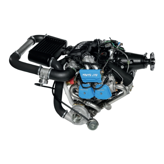
- Page 1 AIRCRAFT ENGINES Maintenance Manual (HeAvy MAintenAnce) for rotAx® engine tyPe 915 i A SerieS ref. no.: MMH-915 i A | part no.: 898861 picture: rotAx® 915 i A with options...
- Page 2 GmbH & CO KG, Austria, acc, BGBI 1984 no. 448, and shall not, without prior written permission of BRP-Rotax GmbH & Co KG, be disclosed in whole or in part to third parties. This legend shall be included on any reproduction of these data, in whole or in part. The Manual must remain with the engine/aircraft in case of sale.
- Page 3 76–70–00 – Sensors and actuators Chapter 78–00–00 – Exhaust system Chapter 78–10–00 – Exhaust Chapter 78–20–00 – Turbocharger Chapter 79–00–00 – Lubrication system Chapter 80–00–00 – Electric starter Effectivity: 915 i A Series Content Edition 0/Rev. 0 Page 1 August 01 2018...
- Page 4 BRP-Rotax MAINTENANCE MANUAL HEAVY NOTES Notes Effectivity: 915 i A Series Edition 0/Rev. 0 Page 2 August 01 2018...
- Page 5 ROTAX® authorized Aircraft Engines Distributors or their independent Service Center. BRP-Rotax wishes you much pleasure and satisfaction flying your aircraft powered by this ROTAX®-aircraft engine. The structure of the Manual follows whenever it is possible the structure of the ATA (Air Transport Association) standards.
- Page 6 BRP-Rotax MAINTENANCE MANUAL HEAVY NOTES Notes Effectivity: 915 i A Series Edition 0/Rev. 0 Page 2 August 01 2018...
- Page 7 August 01 2018 August 01 2018 August 01 2018 August 01 2018 August 01 2018 August 01 2018 24-20-00 August 01 2018 August 01 2018 August 01 2018 Effectivity: 915 i A Series Edition 0/Rev. 0 Page 1 August 01 2018...
- Page 8 August 01 2018 August 01 2018 August 01 2018 August 01 2018 August 01 2018 August 01 2018 August 01 2018 August 01 2018 August 01 2018 Effectivity: 915 i A Series Edition 0/Rev. 0 Page 2 August 01 2018...
- Page 9 August 01 2018 August 01 2018 August 01 2018 August 01 2018 August 01 2018 August 01 2018 August 01 2018 August 01 2018 August 01 2018 Effectivity: 915 i A Series Edition 0/Rev. 0 Page 3 August 01 2018...
- Page 10 August 01 2018 August 01 2018 August 01 2018 August 01 2018 August 01 2018 August 01 2018 August 01 2018 August 01 2018 August 01 2018 Effectivity: 915 i A Series Edition 0/Rev. 0 Page 4 August 01 2018...
- Page 11 August 01 2018 August 01 2018 August 01 2018 August 01 2018 August 01 2018 August 01 2018 August 01 2018 August 01 2018 August 01 2018 Effectivity: 915 i A Series Edition 0/Rev. 0 Page 5 August 01 2018...
- Page 12 August 01 2018 August 01 2018 August 01 2018 August 01 2018 August 01 2018 August 01 2018 August 01 2018 August 01 2018 August 01 2018 Effectivity: 915 i A Series Edition 0/Rev. 0 Page 6 August 01 2018...
- Page 13 August 01 2018 August 01 2018 August 01 2018 August 01 2018 August 01 2018 76-50-00 August 01 2018 August 01 2018 August 01 2018 August 01 2018 Effectivity: 915 i A Series Edition 0/Rev. 0 Page 7 August 01 2018...
- Page 14 August 01 2018 78-00-00 August 01 2018 August 01 2018 August 01 2018 August 01 2018 August 01 2018 August 01 2018 August 01 2018 August 01 2018 Effectivity: 915 i A Series Edition 0/Rev. 0 Page 8 August 01 2018...
- Page 15 August 01 2018 August 01 2018 August 01 2018 August 01 2018 August 01 2018 August 01 2018 August 01 2018 August 01 2018 August 01 2018 Effectivity: 915 i A Series Edition 0/Rev. 0 Page 9 August 01 2018...
- Page 16 BRP-Rotax MAINTENANCE MANUAL HEAVY NOTES Notes Effectivity: 915 i A Series Edition 0/Rev. 0 Page 10 August 01 2018...
- Page 17 August 01 2018 DOA* 74-20-00 August 01 2018 DOA* 75-00-00 August 01 2018 DOA* 76-00-00 August 01 2018 DOA* 76-10-00 August 01 2018 DOA* 76-20-00 August 01 2018 DOA* Effectivity: 915 i A Series Edition 0/Rev. 0 Page 1 August 01 2018...
- Page 18 August 01 2018 DOA* 78-00-00 August 01 2018 DOA* 78-10-00 August 01 2018 DOA* 78-20-00 August 01 2018 DOA* 79-00-00 August 01 2018 DOA* 80-00-00 August 01 2018 DOA* Effectivity: 915 i A Series Edition 0/Rev. 0 Page 2 August 01 2018...
- Page 19 MAINTENANCE MANUAL HEAVY Summary of amendments Summary of the relevant amendments in this context, but without any claim to completeness. Current Chapter Page Date of Comment change Effectivity: 915 i A Series Edition 0/Rev. 0 Page 3 August 01 2018...
- Page 20 BRP-Rotax MAINTENANCE MANUAL HEAVY NOTES Notes Effectivity: 915 i A Series Edition 0/Rev. 0 Page 4 August 01 2018...
-
Page 21: Table Of Contents
Use for intended purpose ........................16 Inspection of parts and report of findings....................17 Classification of parts for maintenance/repair..................19 Maintenance ............................22 Fastener information..........................23 LOCTITE Application procedure ......................24 Lubricant ...............................29 Tools ..............................33 Effectivity: 915 i A Series 00–00–00 Edition 0/Rev. 0 Page 1 August 01 2018... -
Page 22: General
ROTAX® authorized Aircraft Engines distributor or their independent Service Center. ROTAX Distributors For ROTAX® Authorized Distributors for aircraft engines see latest Operators Manual or the official website www.FLYROTAX.com. Engine serial number When making inquiries or ordering parts, always indicate the engine serial number. Due to continuous product improvement, engines of the same engine type might require different support and spare parts. -
Page 23: Type Description
Approved to ASTM F2339. Configuration Propeller shaft with flange for constant speed propeller and drive for hydraulic governor for constant speed propeller. Additional Standard version designation Effectivity: 915 i A Series 00–00–00 Edition 0/Rev. 0 Page 3 August 01 2018... -
Page 24: Abbreviations And Terms
Controller Area Network Coil 1–4 Ignition coils 1–4 CPS 1+2 Crankshaft Position Sensor 1+2 Constant Speed Actuator Cooling Temperature Sensor clockwise counter-clockwise CGSB Canadian General Standards Board 00–00–00 Effectivity: 915 i A Series Edition 0/Rev. 0 Page 4 August 01 2018... - Page 25 MAPS 1 & 2 Manifold Air Pressure Sensor 1 & 2 MATS 1 & 2 Manifold Air Temperature Sensor 1 & 2 Motor Octane Number Magneto Side Effectivity: 915 i A Series 00–00–00 Edition 0/Rev. 0 Page 5 August 01 2018...
- Page 26 Production Organisation Approval PTFE Polytetrafluoroethylene (Teflon) Power Take Off Rev. Revision ROTAX® is a trademark of BRP-Rotax GmbH & Co KG Research Octane Number RON 424 ROTAX® Norm 424 s.v. still valid (only Illustrated Parts Catalog) Serial Number Society of Automotive Engineers...
- Page 27 Time Since New TSNP Time Since New Part Time Since Overhaul Volt Visual Flight Rules List of Effective Pages Maintenance Manual XXXX shows the serial component number Effectivity: 915 i A Series 00–00–00 Edition 0/Rev. 0 Page 7 August 01 2018...
-
Page 28: Conversion Table
1 bar = 100 000 Pa / 1000 hPa / 100 kPa 14 —> 2.1 1 bar = 14.503 lbf/in² (psi) 16 —> 1.3 1 in Hg = 33.8638 hPa 18 —>0.8 20—> 0.52 00–00–00 Effectivity: 915 i A Series Edition 0/Rev. 0 Page 8 August 01 2018... -
Page 29: Safety Notice
The information and descriptions of components and systems contained in this Manual are correct at the time of publication. BRP-Rotax maintains a policy of continuous im- provement of its products without imposing upon itself any obligation to retrofit products previously manufactured. -
Page 30: Safety Information
• Due to the varying designs, equipment and types of aircraft, BRP-Rotax grants no war- ranty on the suitability of its engines use on any particular aircraft. Further, BRP-Rotax... - Page 31 • Improper engine installation, use of unsuitable piping for fuel, cooling and lubrication system and use of unsuitable wiring for electric and engine management system re- leases the engine manufacturer from any liability Effectivity: 915 i A Series 00–00–00 Edition 0/Rev. 0...
-
Page 32: Instruction
Spare parts must meet the requirements defined by the engine manufacturer.This can only be guaranteed when using GENUINE-ROTAX®-spare parts and/or accessories (see IPC). Spare parts are available at ROTAX® Authorized Distributors and their inde- pendent Service Centers. Any warranty by BRP-Rotax will become void if spare parts and/ or accessories other than GENUINE-ROTAX®-spare parts and/or accessories are... -
Page 33: Maintenance Concept
"Line Maintenance". NOTE This Manual can only be used in combination with Maintenance Manual I (Line Maintenance), as it builds upon it. Effectivity: 915 i A Series 00–00–00 Edition 0/Rev. 0 Page 13... -
Page 34: Technical Documentation
BRP-Rotax MAINTENANCE MANUAL HEAVY TECHNICAL DOCUMENTATION These documents form the instructions ensuring continued airworthiness of ROTAX® air- craft engines. The information contained herein is based on data and experience that are considered ap- plicable for authorized mechanics (iRMT, see Maintenance Manual Line) under normal conditions for engine removal and installation. - Page 35 Installation drawings Installation drawings and a DMU-model for (virtual) installation analysis are available from the ROTAX® Authorized Distributors or their independent Service Centers on special re- quest and relevant non disclosure and copyright regulations. The illustrations in this Manual show a possible installation variant including non certified parts.
-
Page 36: Use For Intended Purpose
Flying components can cause serious injuries. Never run an engine without propeller. The engine ROTAX® 915 iSc is intended for use in certified aircraft. In case of doubt the regulations of the national authorities or the respective sportive federations have to be observed. -
Page 37: Inspection Of Parts And Report Of Findings
• The maximum limits for wear are divided into the columns maximum wear 100 % (2) and 50 % wear (3) • The first line (4) gives the maximum permissible value in [mm], the second line (5) in [inches] Effectivity: 915 i A Series 00–00–00 Edition 0/Rev. 0 Page 17... - Page 38 Where measurement values are taken in hundredths of a millimeter or more precisely, the temperature of the part must be 20 to 25 °C (68 to 77 °F). 00–00–00 Effectivity: 915 i A Series Edition 0/Rev. 0 Page 18 August 01 2018...
-
Page 39: Classification Of Parts For Maintenance/Repair
• The classification is carried out as per following table: TSN [h] max. permissible wear Time Since New for repair [%] from TBO 1200 h – 915 i Series 1000 Effectivity: 915 i A Series 00–00–00 Edition 0/Rev. 0 Page 19 August 01 2018... - Page 40 New dimension (max) Wear limit New dimension tolerance Wear tolerance Actual dimension ATTENTION New dimension (max.) B is always the dimension which is closest to wear limit C. 00–00–00 Effectivity: 915 i A Series Edition 0/Rev. 0 Page 20 August 01 2018...
- Page 41 28.10 mm (1.1062 in.) Actual dimension 28.07 mm (1.1051 in.) Actual wear 57.1% This part must be replaced because it is excessively worn for only 300 hours of operation. Effectivity: 915 i A Series 00–00–00 Edition 0/Rev. 0 Page 21 August 01 2018...
-
Page 42: Maintenance
Some parts must be torqued according to a specific sequence and torque pattern as detailed in the installation procedure. 00–00–00 Effectivity: 915 i A Series Edition 0/Rev. 0 Page 22 August 01 2018... -
Page 43: Fastener Information
Allow the solvent time to act, then wipe off or blow out with shop air. Solvent uti- lization is to ensure proper adhesion of the product used for locking the fastener. Figure 1.4: Fastener Information Effectivity: 915 i A Series 00–00–00 Edition 0/Rev. 0... -
Page 44: Loctite Application Procedure
Choose proper strength LOCTITE thread locker. Fit bolt in the hole. Apply a few drops of thread locker at proposed tightened nut engagement area. Position nut and tighten as required. 00–00–00 Effectivity: 915 i A Series Edition 0/Rev. 0 Page 24 August 01 2018... - Page 45 Choose proper strength LOCTITE thread locker. Apply several drops along the threaded hole and at the bottom of the hole. Apply several drops on bolt threads. Tighten as required. Effectivity: 915 i A Series 00–00–00 Edition 0/Rev. 0 Page 25...
- Page 46 Apply several drops of proper strength LOCTITE on stud threads. Install stud. Install cover, part, etc. Apply a few drops of proper strength LOCTITE on uncovered stud threads. Install and tighten retaining nut(s) as required. 00–00–00 Effectivity: 915 i A Series Edition 0/Rev. 0 Page 26 August 01 2018...
- Page 47 Avoid touching metal with tip of flask. NOTE For preventive maintenance on existing equipment, retighten nuts and apply prop- er strength LOCTITE on bolt/nut contact surfaces. Effectivity: 915 i A Series 00–00–00 Edition 0/Rev. 0 Page 27 August 01 2018...
- Page 48 Avoid touching metal with tip of flask. NOTE If it is difficult to readjust, heat screw with a soldering iron (232 °C) (450 °F). 00–00–00 Effectivity: 915 i A Series Edition 0/Rev. 0 Page 28 August 01 2018...
-
Page 49: Lubricant
LUBRICANT Consumable materials ATTENTION Use only the specified or technically equivalent materials from BRP-Rotax for all maintenance work. When handling chemicals, comply with all the customary reg- ulations and specifications of the producer, including the expiry date and instruc- tions of use. - Page 50 Part no. Description, application Qty. 898570 Screw securing paint 20 ml Seals screws 899789 LOCTITE 603 10 ml Oil tolerant retaining compound, heavy-duty Figure 1.10: Lubricant tools 00–00–00 Effectivity: 915 i A Series Edition 0/Rev. 0 Page 30 August 01 2018...
- Page 51 (CASTROL ZA 30 or OMV - SOFT SOL). When using solvents, ob- serve the safety regulations for persons and the environment. Effectivity: 915 i A Series 00–00–00 Edition 0/Rev. 0 Page 31 August 01 2018...
- Page 52 These deposits are then involved in a chemical reaction (especially of the sulfur and lead content of AVGAS) with the valve material. This effect may cause hot-gas corrosion on the affected parts. 00–00–00 Effectivity: 915 i A Series Edition 0/Rev. 0 Page 32 August 01 2018...
-
Page 53: Tools
• Electronic, 3 1/2 digit indication • Current range 10 A • Direct voltage range 200 V minimum • Resistance range 200 Ω to 2 MΩ • Acoustic continuity tester Effectivity: 915 i A Series 00–00–00 Edition 0/Rev. 0 Page 33 August 01 2018... - Page 54 BRP-Rotax MAINTENANCE MANUAL HEAVY NOTES Notes Effectivity: 915 i A Series Edition 0/Rev. 0 Page 34 August 01 2018...
- Page 55 Controller connector — assembly ......................18 Crankshaft position sensor assy. (CPS_1/CPS_2) — installation.............19 Installation.............................20 Fly wheel assy. — Installation .......................20 Ignition housing assy. — installation......................20 Finishing work .............................23 Effectivity: 915 i A Series 24–20–00 Edition 0/Rev. 0 Page 1 August 01 2018...
- Page 56 BRP-Rotax MAINTENANCE MANUAL HEAVY Figure 2.1: Location on the engine 24–20–00 Effectivity: 915 i A Series Edition 0/Rev. 0 Page 2 August 01 2018...
-
Page 57: Special Tools
BRP-Rotax MAINTENANCE MANUAL HEAVY SPECIAL TOOLS Description Part number Puller assy. 876010 Insertion jig 876020 Protection mushroom 877419 Figure 2.2: Special Tools Effectivity: 915 i A Series 24–20–00 Edition 0/Rev. 0 Page 3 August 01 2018... -
Page 58: Service Products
Part number LOCTITE 243 897651 LOCTITE 648 899788 LOCTITE 603 899789 LOCTITE 5910 899791 n. a. LOCTITE 7063 n. a. Engine oil n. a. Abrasive pad 24–20–00 Effectivity: 915 i A Series Edition 0/Rev. 0 Page 4 August 01 2018... - Page 59 BRP-Rotax MAINTENANCE MANUAL HEAVY Figure 2.3: Service Products Effectivity: 915 i A Series 24–20–00 Edition 0/Rev. 0 Page 5 August 01 2018...
-
Page 60: System Description
BRP-Rotax MAINTENANCE MANUAL HEAVY SYSTEM DESCRIPTION BEFORE THE INTERNAL GENERATOR IS REMOVED The ROTAX® engine type 915 i A Series has an electronically controlled double-ignition system with ATTENTION an integrated generator. If these checks are omitted, it may be neces-... -
Page 61: Removal
Use appropriate protective coverings to prevent the ingress of foreign bodies into connected lines and connections. Drain coolant. See Maintenance Manual Line for the engine type 915 i A Series. Figure 2.4 • Remove adjacent assemblies (electric starter, water pump). - Page 62 The ignition housing has one dowel pin. Step Procedure Loosen 5 Allen screws M6x30 and 2 Allen screws M6x50 with washer 6.4. Disconnect OPS pressure sensor. 24–20–00 Effectivity: 915 i A Series Edition 0/Rev. 0 Page 8 August 01 2018...
-
Page 63: Fly Wheel Assy. Removal
BRP-Rotax MAINTENANCE MANUAL HEAVY FLY WHEEL ASSY. REMOVAL Preparation Fix the crankshaft. See Maintenance Manual Line for the en- gine type 915 i A Series. Step Procedure Loosen 6 Allen screws M6x12. Remove the fly wheel. NOTE Figure 2.9 The location of the fly wheel does not have to be Puller assy. - Page 64 Bend back the retaining tab and at the disk springs and distance sleeve. same time carefully pull on the cable until the terminal is detached. Remove the adjustment screw and lead through seal. 24–20–00 Effectivity: 915 i A Series Edition 0/Rev. 0 Page 10 August 01 2018...
- Page 65 Stator assy. Figure 2.17: TYPICAL Step Procedure Push the grommet in and pull the cable Disk springs (6 pcs.) Distance sleeve out. Washer 5.1/15.5/2.5 Lock nut M5 Effectivity: 915 i A Series 24–20–00 Edition 0/Rev. 0 Page 11 August 01 2018...
-
Page 66: Crankshaft Position Sensor Assy. (Cps_1, Cps_2) - Removal
CRANKSHAFT POSITION SENSOR ASSY. (CPS_1, CPS_2) — REMOVAL To remove the crankshaft position sensor see Chap- ter 76-70-00 section Crankshaft position sensor assy. (CPS_1, CPS_2) — removal. 24–20–00 Effectivity: 915 i A Series Edition 0/Rev. 0 Page 12 August 01 2018... -
Page 67: Inspection
If the bearing bushing is worn, the entire ignition housing must be replaced. Effectivity: 915 i A Series 24–20–00 Edition 0/Rev. 0 Page 13... -
Page 68: Stator Assy. - Inspection
CRANKSHAFT POSITION SENSOR (CPS_1/CPS_2) — INSPECTION To inspect the crankshaft position sensor see Chap- ter 76-70-00 section Crankshaft position sensor (CPS_1/CPS_2) — inspection. 24–20–00 Effectivity: 915 i A Series Edition 0/Rev. 0 Page 14 August 01 2018... -
Page 69: Wear Limits
0.0020 in. 0.0047 in. 0.0033 in. current Crankshaft end CS05 27.970 mm 28.000 mm 27.930 mm 27.950 mm replaced 1.1012 in. 1.103 in. 1.0996 in. 1.1004 in. Effectivity: 915 i A Series 24–20–00 Edition 0/Rev. 0 Page 15 August 01 2018... -
Page 70: Assembly
Using a soft-faced hammer, tap the oil Figure 2.27 seal with the insertion jig to press it in to the ignition housing. Washer (Shim) Oil seal 24–20–00 Effectivity: 915 i A Series Edition 0/Rev. 0 Page 16 August 01 2018... -
Page 71: Stator Assy. - Installation
Separation paper between the two generator coils Allen screw M5x30 Washer A 5.5 Figure 2.31 Step Procedure Adjustment screw Rubber grommet Install the distance sleeve, disk springs M4x8 and washer. Effectivity: 915 i A Series 24–20–00 Edition 0/Rev. 0 Page 17 August 01 2018... -
Page 72: Controller Connector - Assembly
NOTE See also relevant Illustrated Parts Catalog Cables of generator B are thicker than cables of for the 915 i A Series engine type. generator A. Cables of generator B are yellow.. 24–20–00 Effectivity: 915 i A Series Edition 0/Rev. -
Page 73: Crankshaft Position Sensor Assy. (Cps_1/Cps_2) - Installation
The bends of the cable clamps must be installed in a diametrically opposed manner (back to back). Step Procedure Adjust cables. Tighten Allen screw M6x20. Tightening torque 10 Nm (89 in. lb.). Effectivity: 915 i A Series 24–20–00 Edition 0/Rev. 0 Page 19 August 01 2018... -
Page 74: Installation
IGNITION HOUSING ASSY. — INSTALLATION Figure 2.39 Ignition housing screw diagram Preparation Bearing bushing Oil seal • Check whether dowel pin has been inserted O-ring 5x2 Crankshaft stub 24–20–00 Effectivity: 915 i A Series Edition 0/Rev. 0 Page 20 August 01 2018... - Page 75 Make sure screw of puller assy. is rotated inwards so the ignition cover is not pulled towards the engine. Step Procedure Install ignition housing on the crankcase with puller assy. part no. 876010. Effectivity: 915 i A Series 24–20–00 Edition 0/Rev. 0 Page 21 August 01 2018...
- Page 76 Fasten hex. screws M5x45. Tightening The engine is not leakproof if this screw is not torque 5 Nm (44 in. lb.) seated with LOCTITE 243. 24–20–00 Effectivity: 915 i A Series Edition 0/Rev. 0 Page 22 August 01 2018...
-
Page 77: Finishing Work
• Install airbox on ignition housing. Chapter 73-00-00 section Fuel system. Release crankshaft. See Maintenance Manual Line for the en- gine type 915 i A Series. • Install CPS sensors. Chapter 76-70-00 section Sensors and actuators. Figure 2.45 Hex. screw M5x45 Hex. - Page 78 BRP-Rotax MAINTENANCE MANUAL HEAVY NOTES Notes Effectivity: 915 i A Series Edition 0/Rev. 0 Page 24 August 01 2018...
- Page 79 Ball bearing — installation ........................13 Needle bearing and oil inlet — installation .....................14 Governor drive — installation .......................14 Governor flange — installation......................14 Governor installation..........................16 Finishing work .............................16 Effectivity: 915 i A Series 61–20–00 Edition 0/Rev. 0 Page 1 August 01 2018...
- Page 80 BRP-Rotax MAINTENANCE MANUAL HEAVY Figure 3.1: Location on the engine 61–20–00 Effectivity: 915 i A Series Edition 0/Rev. 0 Page 2 August 01 2018...
-
Page 81: Special Tools
SPECIAL TOOLS Description Part number Puller 876489 Insertion jig assy. 276332 Retaining device 242661 Ring spanner a/f 10/13 876470 Press-in mushroom 877595 Press-in mushroom 877597 Figure 3.2 Effectivity: 915 i A Series 61–20–00 Edition 0/Rev. 0 Page 3 August 01 2018... -
Page 82: Service Products
BRP-Rotax MAINTENANCE MANUAL HEAVY SERVICE PRODUCTS Description Part number LOCTITE 243 897651 LOCTITE 648 899788 n.a. Engine oil 61–20–00 Effectivity: 915 i A Series Edition 0/Rev. 0 Page 4 August 01 2018... - Page 83 BRP-Rotax MAINTENANCE MANUAL HEAVY Figure 3.3: Hydraulic governor Effectivity: 915 i A Series 61–20–00 Edition 0/Rev. 0 Page 5 August 01 2018...
-
Page 84: System Description
MAINTENANCE As well as the maintenance and special checks, see Maintenance Manual Line for the engine type 915 i A Series. 61–20–00 Effectivity: 915 i A Series Edition 0/Rev. 0 Page 6... -
Page 85: Removal
Oil pump housing 10 Turbo pressure oil line Figure 3.5 Allen screws M6x16 Allen screws M6x20 Governor flange O-ring 7x2-N O-ring 32x4-N Spacer 25/31.95/13 Effectivity: 915 i A Series 61–20–00 Edition 0/Rev. 0 Page 7 August 01 2018... -
Page 86: Governor Drive - Removal
Figure 3.6 Retaining tool part no. Drive sleeve 242661 and 876470 Vacuum pump gear Allen screw M8x16 Figure 3.8 Insertion jig part no. Needle bearing 276332 61–20–00 Effectivity: 915 i A Series Edition 0/Rev. 0 Page 8 August 01 2018... -
Page 87: Needle Bearing And Oil Inlet Flange- Removal
BRP-Rotax MAINTENANCE MANUAL HEAVY NEEDLE BEARING AND OIL INLET FLANGE— REMOVAL Chapter 72-10-00 section Propeller gearbox. Effectivity: 915 i A Series 61–20–00 Edition 0/Rev. 0 Page 9 August 01 2018... -
Page 88: Inspection
Procedure General visual inspection. See Maintenance Manual Line for the en- Check the gear-tooth system of the drive gine type 915 i A Series. gear and vacuum pump gear. • Clean all parts carefully. ATTENTION The M8 fastening screw for the vacuum pump... -
Page 89: Finishing Work
BRP-Rotax MAINTENANCE MANUAL HEAVY Figure 3.11: Typical Governor flange FINISHING WORK • Install the propeller gearbox, see Chapter 72-10- 00 section Propeller gearbox. Effectivity: 915 i A Series 61–20–00 Edition 0/Rev. 0 Page 11 August 01 2018... -
Page 90: Wear Limits
BRP-Rotax MAINTENANCE MANUAL HEAVY WEAR LIMITS Figure 3.12: Intermediate shaft, Torsion shaft For detailed information and measurements see Chapter 72-10-00 section Wear Limits 61–20–00 Effectivity: 915 i A Series Edition 0/Rev. 0 Page 12 August 01 2018... -
Page 91: Installation
877597 on the needle sleeve and fix it with the hex. nut. Figure 3.14 Puller part no. 876489 Hex. screw Washer Hex. nut Press-in mushroom Ball bearing part no. 877595 Effectivity: 915 i A Series 61–20–00 Edition 0/Rev. 0 Page 13 August 01 2018... -
Page 92: Needle Bearing And Oil Inlet - Installation
242661. Secure Allen screw M8x16 with LOCTITE 648 and tighten it. Tightening torque 25 Nm (18 ft.lb). 61–20–00 Effectivity: 915 i A Series Edition 0/Rev. 0 Page 14 August 01 2018... - Page 93 Tightening torque 12 Nm (106 in.lb). Fasten the governor pressure oil line with the cable clamp using the hex. screw M8x25 and LOCTITE 243. Tightening torque 15 Nm (133 in.lb.). Effectivity: 915 i A Series 61–20–00 Edition 0/Rev. 0 Page 15 August 01 2018...
-
Page 94: Governor Installation
The plug screws usually remain installed. If necessary, a manometer can be con- nected to check the governor pressure. Secure the 2 plug screw M8x1 with LOC- TITE 243. 61–20–00 Effectivity: 915 i A Series Edition 0/Rev. 0 Page 16 August 01 2018... - Page 95 Engine suspension frame........................25 Removal of the engine suspension frame ....................25 Inspection .............................27 Engine suspension frame check ......................27 Installation.............................28 Installation of the engine suspension frame ...................28 Finishing work .............................28 Effectivity: 915 i A Series 71–00–00 Edition 0/Rev. 0 Page 1 August 01 2018...
- Page 96 BRP-Rotax MAINTENANCE MANUAL HEAVY Figure 4.1: Power plant 71–00–00 Effectivity: 915 i A Series Edition 0/Rev. 0 Page 2 August 01 2018...
-
Page 97: Special Tools
SPECIAL TOOLS Description Part number Engine lifting kit assy. 876040 Trestle support 877930 Trestle adapter assy. 876050 Socket driver hex. 8 ball head 876240 Figure 4.2 Effectivity: 915 i A Series 71–00–00 Edition 0/Rev. 0 Page 3 August 01 2018... -
Page 98: Installation Checklist
See also Chapter 71–00–00 section Power plant.. Protective coverings removed. Fuel filters/prefilters on the aircraft frame side cleaned. All fuel tanks and fuel lines cleaned. 71–00–00 Effectivity: 915 i A Series Edition 0/Rev. 0 Page 4 August 01 2018... - Page 99 Engine test run/functional test. See relevant Maintenance Manual Line Chapter 12–20–00. General notes/remars: (Please fill in using block capitals!) (Please fill in using block capitals!) Location:_______________________________Date: ___________________________ Signature: _________________________ Effectivity: 915 i A Series 71–00–00 Edition 0/Rev. 0 Page 5 August 01 2018...
-
Page 100: General Note
• Replace or function test injectors at authorized engine overhaul shop. The manufacturer BRP-Rotax guarantees satisfac- tory corrosion protection of the 915 i A Series aircraft NOTE engines for at least 12 months from the BRP-Rotax If there is any corrosion of the components, the delivery date. -
Page 101: Treating Rust And Surface Damage
• Propeller shaft — To prevent surface rust, the flange should be lightly greased, see Chapter 72- 00-00. • For the electric system, see Chapter 74-00-00. Effectivity: 915 i A Series 71–00–00 Edition 0/Rev. 0 Page 7 August 01 2018... -
Page 102: System Description
BRP-Rotax MAINTENANCE MANUAL HEAVY SYSTEM DESCRIPTION DESCRIPTION OF DESIGN A ROTAX® 915 i A Series engine consists basically of several main components and add-on assemblies, which are described in more detail in the Operators Manual (chap- ter 1). 71–00–00 Effectivity: 915 i A Series Edition 0/Rev. -
Page 103: Technical Data
Detailed technical data relevant for operation is listed in the Operators Manual and must be observed. OPERATING LIMITS See the current 915 i A Series Operators Manual, “Operating instructions”. OPERATING FLUIDS/CAPACITIES See the current 915 i A Series Operators Manual, “Operating media”. - Page 104 Oil pressure See latest Operators Manual of the respective 915 i A Series engine type. Oil delivery rate 1) Main oil pump: approx. 9 l/min. at 5500 rpm 2) Suction pump circuit: approx 1.3 l/min.
-
Page 105: Serial And Part No
Figure 4.3: e.g. serial number PART NO. The part number consists of a simple six-digit num- ber block. This number block is a consecutive number. Figure 4.4: e.g. part no. Effectivity: 915 i A Series 71–00–00 Edition 0/Rev. 0 Page 11 August 01 2018... -
Page 106: Engine Components, Engine Views, Cylinder Designation And Definition Of Main Axes
Allow ± 1 mm on all stated dimensions as manufacturing tolerance x, y, z Coordinate system axes Cyl. 1 Cylinder 1 Cyl. 2 Cylinder 2 Cyl. 3 Cylinder 3 Cyl. 4 Cylinder 4 71–00–00 Effectivity: 915 i A Series Edition 0/Rev. 0 Page 12 August 01 2018... - Page 107 Propeller gearbox Connection for oil return line Attachment points (for engine handling) Connection for oil return line Center of gravity (Z) Reference coordinate system (X, Y, Z) Effectivity: 915 i A Series 71–00–00 Edition 0/Rev. 0 Page 13 August 01 2018...
- Page 108 Figure 4.6: front view Oil pump Oil filter Exhaust flange Muffler assy. Fuel line assy. Crankshaft locking screw position Wastegate controller Connection for Turbo oil return Wastegate shaft 71–00–00 Effectivity: 915 i A Series Edition 0/Rev. 0 Page 14 August 01 2018...
- Page 109 Expansion tank assy. Fuel rail (right, left) POP Off valve Inter cooler Connection for fuel feed line Attachment points (for engine transport) Connection for fuel return line Effectivity: 915 i A Series 71–00–00 Edition 0/Rev. 0 Page 15 August 01 2018...
- Page 110 BRP-Rotax MAINTENANCE MANUAL HEAVY Figure 4.8 Ignition housing Electric starter Water pump housing Engine suspension frame (ring mount) Turbocharger assy. Solenoid valve (PCV) Fuel pressure regulator 71–00–00 Effectivity: 915 i A Series Edition 0/Rev. 0 Page 16 August 01 2018...
-
Page 111: Maintenance
BRP-Rotax MAINTENANCE MANUAL HEAVY MAINTENANCE For maintenance and special checks, see Maintenance Manual Line for the engine type 915 i A Series. Effectivity: 915 i A Series 71–00–00 Edition 0/Rev. 0 Page 17 August 01 2018... -
Page 112: Power Plant
Remove the spinner and propeller. See Remove sensors according to the aircraft also Chapter 61-00-00. manufacturer's instructions. Disconnect sensors according to the air- craft manufacturer’s instructions. 71–00–00 Effectivity: 915 i A Series Edition 0/Rev. 0 Page 18 August 01 2018... - Page 113 Push in the tab on the top of the connec- tor and at the same time pull the connec- tor out of the connection socket. Effectivity: 915 i A Series 71–00–00 Edition 0/Rev. 0 Page 19 August 01 2018...
- Page 114 Press the clamp down until it latches. NOTE Loosen the connector cap nut coun- ter-clockwise. Pull the connectors in the two grooves out of the connector socket. 71–00–00 Effectivity: 915 i A Series Edition 0/Rev. 0 Page 20 August 01 2018...
-
Page 115: Removal Of The Power Plant From The Aircraft
Danger of injury due to falling parts!When the engine is removed there is a risk of injury due to the engine or its assemblies falling! Use ROTAX lift set, no other lifting points allowed. Note center of gravity! Do not walk under the lifted engine!Wear protective footwear! Figure 4.16... - Page 116 Completely loosen the screw connections between the engine suspension and the fire wall. Lift the engine out of the aircraft, clean it and prepare it. 71–00–00 Effectivity: 915 i A Series Edition 0/Rev. 0 Page 22 August 01 2018...
-
Page 117: Installation
Preparation cording to the tightening torque values of the aircraft manufacturer. • Secure the aircraft appropriately Remove the lifting gear. • Complete the installation checklist Effectivity: 915 i A Series 71–00–00 Edition 0/Rev. 0 Page 23 August 01 2018... -
Page 118: Connecting The Supply Lines To The Aircraft
Connecting electrical connectors, fuel lines, oil hoses, water hoses between the engine and the aircraft. The supply lines are connected and disconnected the same way. See Chapter 71–00–00 section Removal. 71–00–00 Effectivity: 915 i A Series Edition 0/Rev. 0 Page 24 August 01 2018... -
Page 119: Engine Suspension Frame
ATTENTION On the left-hand side (cylinders 2/4), thrust washers can be installed for tension-free as- sembly. Use as required. Do not lose them! Effectivity: 915 i A Series 71–00–00 Edition 0/Rev. 0 Page 25 August 01 2018... - Page 120 EGT temperature sensor on cylinder 4! Figure 4.24 Figure 4.22 Engine suspension Allen screw M10x110 frame Engine suspension Allen screw M10x50 frame Temperature sensor EGT temperature (coolant) sensor 71–00–00 Effectivity: 915 i A Series Edition 0/Rev. 0 Page 26 August 01 2018...
-
Page 121: Inspection
Figure 4.25 Engine suspension Allen screw M10x110 frame Lock washer A10 Allen screw M10x35 Thrust washer 10.1/20/ Allen screw M10x50 Spacer Washer 10.5 Effectivity: 915 i A Series 71–00–00 Edition 0/Rev. 0 Page 27 August 01 2018... -
Page 122: Installation
(44 ft. lb.), all of them must be secured with LOCTITE 243. FINISHING WORK • Install the water pump. See Chapter 75–00–00. • Install the coolant hoses. See Chapter 75–00–00. 71–00–00 Effectivity: 915 i A Series Edition 0/Rev. 0 Page 28 August 01 2018... - Page 123 Chapter: 72–00–00 ENGINE TOPICS IN THIS CHAPTER System description ..........................3 Safety instruction...........................3 This section describes the maintenance of the ROTAX® 915 i A Series engine. The description is divided into subsections and explanations of system functions. Subject Section Engine Chapter 72-00-00...
- Page 124 BRP-Rotax MAINTENANCE MANUAL HEAVY Figure 5.1: Engine 72–00–00 Effectivity: 915 i A Series Edition 0/Rev. 0 Page 2 August 01 2018...
- Page 125 BRP-Rotax MAINTENANCE MANUAL HEAVY SYSTEM DESCRIPTION The 915 i A Series engine is a 4-cylinder, four-stroke, horizontally opposed engine with manifold injection. This engine has liquid cooled cylinder heads and ram air cooled cylinders; this engine also has a fully...
- Page 126 BRP-Rotax MAINTENANCE MANUAL HEAVY NOTES Notes Effectivity: 915 i A Series Edition 0/Rev. 0 Page 4 August 01 2018...
- Page 127 Assembly of the overload clutch assy....................35 Assembly of the damper clutch assy......................36 Assembly of the propeller gearbox assy....................40 Installation.............................42 Needle bearing — installation .......................42 Finishing work .............................43 Effectivity: 915 i A Series 72–10–00 Edition 0/Rev. 0 Page 1 August 01 2018...
- Page 128 BRP-Rotax MAINTENANCE MANUAL HEAVY Figure 6.1: Location on the engine 72–10–00 Effectivity: 915 i A Series Edition 0/Rev. 0 Page 2 August 01 2018...
-
Page 129: Special Tools
276962 Insertion jig 276964 Insertion jig 276966 Retaining ring tool 276968 Insertion sleeve 276972 Insertion jig 276974 Thread bolt M8x50 240880 n.a. Hand operated hydraulic press Effectivity: 915 i A Series 72–10–00 Edition 0/Rev. 0 Page 3 August 01 2018... - Page 130 BRP-Rotax MAINTENANCE MANUAL HEAVY Figure 6.2 72–10–00 Effectivity: 915 i A Series Edition 0/Rev. 0 Page 4 August 01 2018...
-
Page 131: Service Products
Part number n.a. Engine oil LOCTITE 243 897651 LOCTITE 603 899789 LOCTITE 648 899788 LOCTITE 7063 LITHIUM-BASE GREASE 897330 LOCTITE 5910 899791 297434 LOCTITE ANTI SEIZE 8151 Effectivity: 915 i A Series 72–10–00 Edition 0/Rev. 0 Page 5 August 01 2018... - Page 132 BRP-Rotax MAINTENANCE MANUAL HEAVY Figure 6.3 72–10–00 Effectivity: 915 i A Series Edition 0/Rev. 0 Page 6 August 01 2018...
- Page 133 BRP-Rotax MAINTENANCE MANUAL HEAVY Figure 6.4 Effectivity: 915 i A Series 72–10–00 Edition 0/Rev. 0 Page 7 August 01 2018...
-
Page 134: System Description
Manual regarding connections for instrumentation. MAINTENANCE As well as the maintenance and special checks, see Maintenance Manual Line for the engine type 915 i A Series. 72–10–00 Effectivity: 915 i A Series Edition 0/Rev. 0 Page 8 August 01 2018... -
Page 135: Removal
MAINTENANCE MANUAL HEAVY REMOVAL For removal of the propeller gearbox, see the relevant Maintenance Manual Line for the respective 915 I A Series. TORSION SHAFT— REMOVAL NOTE If the clutches can not be removed, then remove the torsion shaft first. -
Page 136: Disassembly
For removal, warm up the collar nut with a hot air gun. NOTE Alternatively, the hand press can also be used to press out the propeller shaft. 72–10–00 Effectivity: 915 i A Series Edition 0/Rev. 0 Page 10 August 01 2018... -
Page 137: Removal Of The Ball Bearing And Oil Seal
Step Procedure Remove the retaining ring with the circlip pliers. Figure 6.12 Ball bearing Oil seal Effectivity: 915 i A Series 72–10–00 Edition 0/Rev. 0 Page 11 August 01 2018... -
Page 138: Removal Of The Needle Bearing
Install the threaded pin of special tool part no. 276004 through the plunger and the oil inlet flange. Fix it with the knurled nut on the other side. 72–10–00 Effectivity: 915 i A Series Edition 0/Rev. 0 Page 12 August 01 2018... -
Page 139: Disassembly Of The Overload Clutch Assy
276974 Step Procedure Press clutch assy. with insertion jig part no. 276974 until the circlip is free for removal. Remove the circlip using a small screwdriver. Effectivity: 915 i A Series 72–10–00 Edition 0/Rev. 0 Page 13 August 01 2018... -
Page 140: Disassembly Of The Damper Clutch Assy
Centering plate Damper clutch 276954 Figure 6.19 Large chamfer - pro- Centering ring 276950 peller side Circlip Intermediate shaft Steel friction plate 4 Steel friction plate 1.8 72–10–00 Effectivity: 915 i A Series Edition 0/Rev. 0 Page 14 August 01 2018... - Page 141 Now the damper clutch on propeller side Place the damper clutch (propeller side) can be disassembled. on the centering plate part no. 276954 and insert the centering ring part no. 276950. Effectivity: 915 i A Series 72–10–00 Edition 0/Rev. 0 Page 15 August 01 2018...
- Page 142 Steel friction plate 3 Steel friction plate 1 Friction plate 1.54 Steel friction plate 3 Circlip Clutch drum Figure 6.24 Insertion jig Retaining ring 72–10–00 Effectivity: 915 i A Series Edition 0/Rev. 0 Page 16 August 01 2018...
-
Page 143: Inspection
• Indentations up to a maximum of 0.2 mm are permissible. • Bumps up to a maximum of 0.2 mm are permissible. Figure 6.27: Bearing bushing Effectivity: 915 i A Series 72–10–00 Edition 0/Rev. 0 Page 17 August 01 2018... -
Page 144: Propeller Shaft - Check
See Chapter 72-10-00 section Wear Gear-tooth system Propeller shaft limits. Propeller flange Ball bearing seat GB02 Figure 6.28 Ball bearing Outer ring Inner ring 72–10–00 Effectivity: 915 i A Series Edition 0/Rev. 0 Page 18 August 01 2018... -
Page 145: Overload Clutch - Check
Chapter damage and wear. 72-10-00 section Wear limits. Check the overload clutch visually for any deposits (e.g. AVGAS). Measure GB03, see Chapter 72-10-00 section Wear limits. Effectivity: 915 i A Series 72–10–00 Edition 0/Rev. 0 Page 19 August 01 2018... -
Page 146: Damper Clutch - Check
72-10-00 section Wear limits. Procedure Step Check the damper clutch visually for damage and wear. Check the damper clutch visually for any deposits (e.g. AVGAS) 72–10–00 Effectivity: 915 i A Series Edition 0/Rev. 0 Page 20 August 01 2018... -
Page 147: Torsion Bar - Check
Driving collar TORSION BAR - CHECK ATTENTION Torsion bar must not be reworked. Step Procedure Check for corrosion and damage, if nec- essary exchange complete torsion bar. Effectivity: 915 i A Series 72–10–00 Edition 0/Rev. 0 Page 21 August 01 2018... -
Page 148: Checking The Splines
NOTE The likely location of pitting formation is the de- dendum flank of the driving gear. Therefore, be- gin by checking the drive gear. 72–10–00 Effectivity: 915 i A Series Edition 0/Rev. 0 Page 22 August 01 2018... -
Page 149: Pitting, General Information
The rule is however pitting damage which increases over time. A distinction can be made according to the size, type and number of pitting, as follows. Effectivity: 915 i A Series 72–10–00 Edition 0/Rev. 0 Page 23 August 01 2018... -
Page 150: Slight Pitting
The illustrations are sometimes not very infor- mative due to fine pitting or the printing process. If in doubt, consult technical literature or contact the ROTAX® Authorized Distributor or their in- dependent Service Centers. Figure 6.36: Magnification: approx. 1.5x Figure 6.37: Magnification: approx. 1.5x 72–10–00... -
Page 151: Destructive Pitting
ATTENTION The whole gear set must always be replaced. Pitted area in the dedendum flank region of a spur gear. Gears must not be replaced individually. Effectivity: 915 i A Series 72–10–00 Edition 0/Rev. 0 Page 25 August 01 2018... - Page 152 Apart from these, the same causes apply as for pitting. Figure 6.40: Magnification approx. 2x. Triangular flake pitting Figure 6.41: Magnification approx. 2x. Triangular flake pitting 72–10–00 Effectivity: 915 i A Series Edition 0/Rev. 0 Page 26 August 01 2018...
-
Page 153: Wear Limits
BRP-Rotax MAINTENANCE MANUAL HEAVY WEAR LIMITS Effectivity: 915 i A Series 72–10–00 Edition 0/Rev. 0 Page 27 August 01 2018... - Page 154 0.000 mm 0.050 mm 0.060 mm 0.055 mm current GB04 out, propel- 0.000 in. 0.0020 in. 0.0024 in. 0.0022 in. replaced ler flange at Ø 122 mm 72–10–00 Effectivity: 915 i A Series Edition 0/Rev. 0 Page 28 August 01 2018...
- Page 155 0.031 in. 0.034 in. replaced Drive gear 0.95 mm 1.00 mm 0.80 mm 0.88 mm current GB07 replaced 0.037 in. 0.037 in. 0.031 in. 0.034 in. Effectivity: 915 i A Series 72–10–00 Edition 0/Rev. 0 Page 29 August 01 2018...
- Page 156 3mm) Free height current GB20 3.34 mm 3.55 mm 3.10 mm 3.22 mm replaced of disc 0.131 in. 0.140 in. 0.122 in. 0.127 in. springs prop-side 72–10–00 Effectivity: 915 i A Series Edition 0/Rev. 0 Page 30 August 01 2018...
- Page 157 Free height GB21 4.72 mm 4.95 mm 4.30 mm 4.50 mm replaced of disc 0.186 in. 0.195 in. 0.169 in. 0.177 in. springs en- gine-side Effectivity: 915 i A Series 72–10–00 Edition 0/Rev. 0 Page 31 August 01 2018...
-
Page 158: Assembly
Install the retaining ring with circlip pliers. NOTE Place the circlip in the groove with the sharp edge pointing away from bearing. Figure 6.43 Press-in mushroom Insertion jig 877650 276964 Oil seal 72–10–00 Effectivity: 915 i A Series Edition 0/Rev. 0 Page 32 August 01 2018... -
Page 159: Propeller Shaft - Installation
276972. NOTE Do not use high forces for propeller shaft installation, only press-in with the special tool part no. 276972. Effectivity: 915 i A Series 72–10–00 Edition 0/Rev. 0 Page 33 August 01 2018... -
Page 160: Torsion Shaft - Installation
Install O-ring, sealing washer (with sharp Figure 6.48 edge showing upwards) and retaining ring. Propeller shaft Support plate Hand tighten the hex. screw M12x20 with Retaining ring Special tool 276968 washer. 72–10–00 Effectivity: 915 i A Series Edition 0/Rev. 0 Page 34 August 01 2018... -
Page 161: Assembly Of The Overload Clutch Assy
Lay overload clutch assy. on the insertion jig part no. 276974. Figure 6.52 Disc springs Steel friction plate (contrary) Sinter friction plates Steel friction plates (5 pcs.) 1mm(4 pcs.) Effectivity: 915 i A Series 72–10–00 Edition 0/Rev. 0 Page 35 August 01 2018... -
Page 162: Assembly Of The Damper Clutch Assy
Use a hand operated hydraulic press or similar. NOTE Before assembly, lubricate all components with engine oil. Figure 6.54 Support ring Clutch hub Steel friction plate 4 72–10–00 Effectivity: 915 i A Series Edition 0/Rev. 0 Page 36 August 01 2018... - Page 163 Assemble clutch package as shown in fol- lowing figure. NOTE Observe the correct position of the support ring (projection is facing to the top). NOTE Install disc springs contrary to each other. Effectivity: 915 i A Series 72–10–00 Edition 0/Rev. 0 Page 37 August 01 2018...
- Page 164 Observe the correct position of the support ring (projection is facing to the bottom). NOTE Install disc springs contrary to each other. Figure 6.59 Centering ring Insertion jig Circlip 72–10–00 Effectivity: 915 i A Series Edition 0/Rev. 0 Page 38 August 01 2018...
- Page 165 Step Procedure Insert circlip and release damper clutch assy. NOTE Check the alignment of clutch hub once again. It must be free to move. Effectivity: 915 i A Series 72–10–00 Edition 0/Rev. 0 Page 39 August 01 2018...
-
Page 166: Assembly Of The Propeller Gearbox Assy
Install damper clutch into the housing. NOTE There is only one position to install the damper clutch. It is indexed through the splines of the propeller shaft. 72–10–00 Effectivity: 915 i A Series Edition 0/Rev. 0 Page 40 August 01 2018... - Page 167 Overload clutch overload clutch will be raised over the sealing. In this case it needs to be investigated, which pairing is mounted wrong and it has to be fixed. Effectivity: 915 i A Series 72–10–00 Edition 0/Rev. 0 Page 41...
-
Page 168: Installation
NOTE Lubricate needle bearing on outer diameter. Figure 6.67 Oil inlet flange O-ring Scavenge oil hole M6 threaded bores 72–10–00 Effectivity: 915 i A Series Edition 0/Rev. 0 Page 42 August 01 2018... - Page 169 A Series Chapter 05-50-00. Fill with operating fluids or check filling lev- els. See relevant Maintenance Manual Line for the engine type 915 i A Series Chapter 12-10-00 section Adding operat- ing fluids. Carry out an engine test run. See relevant Maintenance Manual Line for the engine Figure 6.69...
- Page 170 BRP-Rotax MAINTENANCE MANUAL HEAVY NOTES Notes Effectivity: 915 i A Series Edition 0/Rev. 0 Page 44 August 01 2018...
- Page 171 Assembly of the sprag clutch housing ....................11 Installation.............................12 Installation of the sprag clutch housing ....................12 Measuring the axial clearance of the free wheel gear ................13 Wear limits ............................14 Finishing work............................15 Effectivity: 915 i A Series 72–20–00 Edition 0/Rev. 0 Page 1 August 01 2018...
-
Page 172: Special Tools
38x20 insert for SW32 hex. nut, mag- 876070 Non certified part neto side crankshaft A 20x12.5 reducing socket 877460 Non certified part Protection mushroom 877419 Non certified part Figure 7.1 72–20–00 Effectivity: 915 i A Series Edition 0/Rev. 0 Page 2 August 01 2018... -
Page 173: Service Products
BRP-Rotax MAINTENANCE MANUAL HEAVY SERVICE PRODUCTS Description Part number LOCTITE ANTI SEIZE 8151 297434 LOCTITE 7063 898450 LOCTITE 603 899789 n.a. Engine oil Effectivity: 915 i A Series 72–20–00 Edition 0/Rev. 0 Page 3 August 01 2018... - Page 174 BRP-Rotax MAINTENANCE MANUAL HEAVY Figure 7.2: Engine block 72–20–00 Effectivity: 915 i A Series Edition 0/Rev. 0 Page 4 August 01 2018...
-
Page 175: General Note
Always allow the engine to cool down to ambient temperature before starting any work. MAINTENANCE As well as the maintenance and special checks, see Maintenance Manual Line for the engine type 915 i A Series. Effectivity: 915 i A Series 72–20–00 Edition 0/Rev. 0 Page 5... -
Page 176: Sprag Clutch
Manual Line for the engine type 915 i A Series. Engine cleaning. See Maintenance Man- ual Line for the engine type 915 i A Series. Carry out an engine test run. See Mainte- nance Manual Line for the engine type915 i A Series. - Page 177 Figure 7.5 Figure 7.7 Protection mushroom Crankshaft Woodruff key Free wheel gear Step Procedure Pull off the sprag clutch housing using the puller part no. 877375. Effectivity: 915 i A Series 72–20–00 Edition 0/Rev. 0 Page 7 August 01 2018...
-
Page 178: Disassembly
Seeger ring pliers and take the sprag clutch out of the sprag clutch housing Circlip while turning it. Figure 7.8 Circlip Seeger ring Sprag clutch housing 72–20–00 Effectivity: 915 i A Series Edition 0/Rev. 0 Page 8 August 01 2018... -
Page 179: Inspection
PARTS CHECK coils are no longer cooled sufficiently. Preparation Clean all parts carefully. See Maintenance Manual Line for the en- gine type 915 i A Series Chapter 05-00-00 section Procedures. SPRAG CLUTCH HOUSING CHECK Procedure Step Check whether oil sludge has accumu- lated in the sprag clutch housing. -
Page 180: Sprag Clutch Check
Check the gear-tooth system of the free wheel gear. Check the sprag clutch engagement face on the free wheel gear. Check the taper surface. Figure 7.14 Starter intermediate Intermediate gear gear shaft 72–20–00 Effectivity: 915 i A Series Edition 0/Rev. 0 Page 10 August 01 2018... -
Page 181: Assembly
Seeger ring pliers and ensure that the Seeger ring remains in posi- tion and latches completely with the teeth in the slots of the sprag clutch body. Effectivity: 915 i A Series 72–20–00 Edition 0/Rev. 0 Page 11 August 01 2018... -
Page 182: Installation
MAINTENANCE MANUAL HEAVY INSTALLATION Preparation Lock the crankshaft into place. For installa- tion see Maintenance Manual Line for the engine type 915 i A Series. INSTALLATION OF THE SPRAG CLUTCH HOUSING ATTENTION Figure 7.18 Approx. 2 to 3 mm on the underside of the... -
Page 183: Measuring The Axial Clearance Of The Free Wheel Gear
Lubricate the intermediate gear shaft and bore of the starter intermediate gear with LOCTITE ANTI SEIZE. Install the starter intermediate gear. Install the intermediate gear shaft. Effectivity: 915 i A Series 72–20–00 Edition 0/Rev. 0 Page 13 August 01 2018... -
Page 184: Wear Limits
100 % 50 % Axial ES10 0.5 mm 1.1 mm 0.2 mm 0.4 mm actual clearance 0.02 in 0.04 in 0.01 in 0.014 in renewed 72–20–00 Effectivity: 915 i A Series Edition 0/Rev. 0 Page 14 August 01 2018... -
Page 185: Finishing Work
Fill with operating fluids or check filling levels. See Maintenance Manual Line for the en- gine type 915 i A Series . Carry out an engine test run. See Maintenance Manual Line for the en- gine type915 i A Series . - Page 186 BRP-Rotax MAINTENANCE MANUAL HEAVY NOTES Notes Effectivity: 915 i A Series Edition 0/Rev. 0 Page 16 August 01 2018...
- Page 187 Coolant elbow — installation ........................28 Valve installation ..........................28 Rocker arm — installation ........................30 Installation.............................31 Cylinder head installation ........................31 Cylinder head (single) repaired per engine side ..................33 Effectivity: 915 i A Series 72–30–00 Edition 0/Rev. 0 Page 1 August 01 2018...
- Page 188 BRP-Rotax MAINTENANCE MANUAL HEAVY Cylinder heads (both) repaired per engine side ..................35 Valve cover installation ........................36 Finishing work .............................37 72–30–00 Effectivity: 915 i A Series Edition 0/Rev. 0 Page 2 August 01 2018...
- Page 189 BRP-Rotax MAINTENANCE MANUAL HEAVY Figure 8.1: Location on the engine Effectivity: 915 i A Series 72–30–00 Edition 0/Rev. 0 Page 3 August 01 2018...
-
Page 190: Special Tools
877380 Non certified part 876130 Socket wrench 19x12.5 Non certified part Torx T30 ball-head insert 876180 Non certified part n.a. Collet Non certified part Figure 8.2 72–30–00 Effectivity: 915 i A Series Edition 0/Rev. 0 Page 4 August 01 2018... -
Page 191: Service Products
BRP-Rotax MAINTENANCE MANUAL HEAVY SERVICE PRODUCTS Description Part number LOCTITE 648 899788 LOCTITE 243 897651 n.a. Engine oil Effectivity: 915 i A Series 72–30–00 Edition 0/Rev. 0 Page 5 August 01 2018... - Page 192 BRP-Rotax MAINTENANCE MANUAL HEAVY Figure 8.3: Cylinder head 72–30–00 Effectivity: 915 i A Series Edition 0/Rev. 0 Page 6 August 01 2018...
-
Page 193: System Description
BRP-Rotax MAINTENANCE MANUAL HEAVY SYSTEM DESCRIPTION The 915 i A Series engine has 4 liquid-cooled cylin- der heads. SAFETY INSTRUCTION m WARNING Danger of severe burns and scalds! Always allow the engine to cool down to ambient temperature before starting any work. -
Page 194: Cylinder Head
General visual inspection. See Maintenance Manual Line for the en- gine type 915 i A Series. Engine cleaning. See Maintenance Manual Line for the en- gine type 915 i A Series. - Page 195 (inlet). See Chapter Coolant hose Protection tube 75-00-00 section Cooling system. Step Procedure Loosen 2 Hex/Torx flange screws M6x20 along and remove the elbow flange. Effectivity: 915 i A Series 72–30–00 Edition 0/Rev. 0 Page 9 August 01 2018...
-
Page 196: Cylinder Head - Removal
CYLINDER HEAD — REMOVAL Procedure Step Loosen the M6x30 screw and washer. Remove the valve cover with the large and small O-rings. Figure 8.10 Collar cap nuts Hex nuts 72–30–00 Effectivity: 915 i A Series Edition 0/Rev. 0 Page 10 August 01 2018... - Page 197 Oil return tubes Procedure Step Hold the oil-filled push-rods closed with a finger, remove them and put them down with the corresponding cylinder heads to prevent confusion. Effectivity: 915 i A Series 72–30–00 Edition 0/Rev. 0 Page 11 August 01 2018...
-
Page 198: Disassembly
Figure 8.12 Cylinder head assy. Valve spring collet Valve spring mounting Right rocker arm Rocker arm shaft device part no. Valve cotter Left rocker arm 877380 72–30–00 Effectivity: 915 i A Series Edition 0/Rev. 0 Page 12 August 01 2018... -
Page 199: Coolant Elbow Inlet - Removal
Remove the elbow flange and O-ring. General visual inspection. See Maintenance Manual Line for the en- NOTE gine type 915 i A Series . Remove the connector brackets on cylinder 3/4. ATTENTION If there are leaks, the corresponding oil return lines must be replaced. - Page 200 Heat the coolant elbow and elbow flange with a hot air gun to max. 120 °C (248 ° Remove the coolant elbow. Remove adhesive residues in the bore and check the thread. 72–30–00 Effectivity: 915 i A Series Edition 0/Rev. 0 Page 14 August 01 2018...
-
Page 201: Inspection
Bumps no greater than 0.1 mm (0.0039 Clean all parts carefully. in.) are permissible. See Maintenance Manual Line for the en- gine type 915 i A Series Chapter 05-00-00 section Procedure. NOTE If the sealing cone of the exhaust manifold CYLINDER HEAD STUDS CHECK leaks, post-machining is permissible. - Page 202 BRP-Rotax MAINTENANCE MANUAL HEAVY Figure 8.19 Sealing surface Spark plug bore 72–30–00 Effectivity: 915 i A Series Edition 0/Rev. 0 Page 16 August 01 2018...
-
Page 203: Hardness Test Method
If the engine has been overheated, a hardness test of the cylinder head is necessary. See Maintenance Manual Line for the en- gine type 915 i A Series . The hardness test takes place at measurement point CH08. CH08: HB2,5/62,5 DIN EN ISO 6506-2 Figure 8.21... -
Page 204: Valve Check
Check that the seal fits properly, if neces- sary touch up small variances with valve lapping paste. AE 2iS_0332 Figure 8.23 Valve stem Valve end face Retaining grooves Max. oil residues 72–30–00 Effectivity: 915 i A Series Edition 0/Rev. 0 Page 18 August 01 2018... -
Page 205: Valve Spring Check
The width of the print corre- sponds to the valve seat width CH02. ATTENTION If there are burn marks or distortion, the cylin- der head must be sent to an ROTAX® author- ised overhaul facility for overhauling or repair. Figure 8.26 Valve spring... -
Page 206: Rocker Arm Check And Rocker Arm Shaft Check
Check the valve support surface and ball joint of the rocker arm. Figure 8.28 72–30–00 Effectivity: 915 i A Series Edition 0/Rev. 0 Page 20 August 01 2018... -
Page 207: Rocker Arm Bushing
The rocker arm bushing is therefore provided with an outer circular groove to allow oil supply. The rocker arm bushing can be installed independently of position. Effectivity: 915 i A Series 72–30–00 Edition 0/Rev. 0 Page 21 August 01 2018... -
Page 208: Wear Limits
WEAR LIMITS CH05 CH05 3 mm 3 mm 0.12 in. 0.12 in. max. 20% ~25 mm ~45 mm ~1.77 in. ~0.98 in. AE 2iS_0341 Figure 8.32 72–30–00 Effectivity: 915 i A Series Edition 0/Rev. 0 Page 22 August 01 2018... - Page 209 BRP-Rotax MAINTENANCE MANUAL HEAVY ~160mm 6.3 in. AE 2iS_0342 Figure 8.33 Effectivity: 915 i A Series 72–30–00 Edition 0/Rev. 0 Page 23 August 01 2018...
- Page 210 0.0016 in. 0.0014 in. placed VT02 0.00 mm 0.03 mm 0.04 mm 0.035 mm current haust 0.0000 in. 0.0012 in. 0.0016 in. 0.0014 in. placed Valve 72–30–00 Effectivity: 915 i A Series Edition 0/Rev. 0 Page 24 August 01 2018...
- Page 211 Bore/ CH05 0.006 mm 0.035 mm 0.150 mm 0.093 mm current rocker haust /VT05 0.0002 in. 0.0014 in 0.0059 in. 0.0036 in. arm shaft Valve placed Effectivity: 915 i A Series 72–30–00 Edition 0/Rev. 0 Page 25 August 01 2018...
- Page 212 0.0079 in. 0.0059 in. placed Push-rod VT09 0.000 mm 0.100 mm 0.200 mm 0.150 mm current haust 0.0000 in. 0.0039 in. 0.0079 in. 0.0059 in. Valve placed 72–30–00 Effectivity: 915 i A Series Edition 0/Rev. 0 Page 26 August 01 2018...
-
Page 213: Assembly
Also coat the thread in the elbow flange with Secure the coolant elbow with LOCTITE LOCTITE 243. 243 and install the elbow in the cold cylin- der head. Effectivity: 915 i A Series 72–30–00 Edition 0/Rev. 0 Page 27 August 01 2018... -
Page 214: Coolant Elbow - Installation
Install the cable brackets on cylinder 2/4. take side. Lubricate the valve stem and push the in- take valve from outside into the valve guide. 72–30–00 Effectivity: 915 i A Series Edition 0/Rev. 0 Page 28 August 01 2018... - Page 215 Step Procedure Install the valve springs and the valve spring retainer Figure 8.40: Typical Mounting device Valve cotter Collet Figure 8.39 Valve spring Valve spring retainer Effectivity: 915 i A Series 72–30–00 Edition 0/Rev. 0 Page 29 August 01 2018...
-
Page 216: Rocker Arm - Installation
Insert the rocker arm shaft. Figure 8.41 Rocker arm shaft Rocker arm 72–30–00 Effectivity: 915 i A Series Edition 0/Rev. 0 Page 30 August 01 2018... -
Page 217: Installation
Raise the cylinder until the centring collar Install the lubricated O-ring 16x5 on the of the cylinder engages into the cylinder oil return tube. head recess. Effectivity: 915 i A Series 72–30–00 Edition 0/Rev. 0 Page 31 August 01 2018... - Page 218 Squeeze the cylinder head and the cylin- der together by hand and push towards crankcase. Lubricate the contact area for the M8 col- lar cap nuts with grease. 72–30–00 Effectivity: 915 i A Series Edition 0/Rev. 0 Page 32 August 01 2018...
-
Page 219: Cylinder Head Installation
• Install the airbox on the ignition housing using an Tightening torque procedure: hex. nut M6 and washer 6.4. To do this, see Chap- 73-10-00 section Airbox installation. Effectivity: 915 i A Series 72–30–00 Edition 0/Rev. 0 Page 33 August 01 2018... - Page 220 • Install the exhaust system. See Chapter 78-00-00 section Exhaust. Fill with coolant. See Maintenance Manual Line for the en- gine type 915 i A Series. Figure 8.47 Airbox Hex. nut M6 Washer 6.4 • Install the spark plugs and connect the spark plug connectors.
- Page 221 (89 in. lb.) + 150°. tighten to 10 Nm (89 in. lb). NOTE This aligns the cylinder heads to en- sure a flat support for the intake manifold. Effectivity: 915 i A Series 72–30–00 Edition 0/Rev. 0 Page 35 August 01 2018...
- Page 222 6.4x1.8 in the valve cover. Place on the valve cover and fasten it with an Allen screw M6x30 and washer. Tightening torque 12 Nm (106 in. lb.). 72–30–00 Effectivity: 915 i A Series Edition 0/Rev. 0 Page 36 August 01 2018...
- Page 223 Chapter 73-10-00 section Fuel pump and distribution. • Install the exhaust system. See Chapter 78-00-00 section Exhaust. • Connect the wiring harness. See Chapter 76-00- 00 section Wiring harness. Effectivity: 915 i A Series 72–30–00 Edition 0/Rev. 0 Page 37 August 01 2018...
- Page 224 BRP-Rotax MAINTENANCE MANUAL HEAVY NOTES Notes Effectivity: 915 i A Series Edition 0/Rev. 0 Page 38 August 01 2018...
- Page 225 Wear limits ............................12 Installation.............................17 Cylinder and piston — installation ......................17 Installation of the hydraulic valve tappet ....................17 Piston — installation ..........................18 Cylinder installation ..........................20 Finishing work .............................21 Effectivity: 915 i A Series 72–30–10 Edition 0/Rev. 0 Page 1 August 01 2018...
- Page 226 BRP-Rotax MAINTENANCE MANUAL HEAVY Figure 9.1 72–30–10 Effectivity: 915 i A Series Edition 0/Rev. 0 Page 2 August 01 2018...
-
Page 227: Special Tools
Non certified parts Piston ring spanner, 84 mm 876967 Non certified parts Monohook circlip remover 976380 Non certified parts Installation tool assy. 877802 Non certified parts Figure 9.2 Effectivity: 915 i A Series 72–30–10 Edition 0/Rev. 0 Page 3 August 01 2018... -
Page 228: Service Products
BRP-Rotax MAINTENANCE MANUAL HEAVY SERVICE PRODUCTS Description Part number LOCTITE ANTI SEIZE 297434 n.a. Engine oil 72–30–10 Effectivity: 915 i A Series Edition 0/Rev. 0 Page 4 August 01 2018... -
Page 229: System Description
BRP-Rotax MAINTENANCE MANUAL HEAVY SYSTEM DESCRIPTION In the 915 i A Series engine, 4 cylinders with "GILNI- SIL"- coated running surfaces are used. The pistons are light alloy full skirt pistons. The piston pin is ax- ially offset by 1 mm (0.03937 in.) with respect to the piston skirt, this is to minimize rocking of the piston. -
Page 230: Removal
Mono hook circlip Pistons Figure 9.3 Circlip remover Cylinders Pistons NOTE Marking arrow Piston pin puller assy. part no. 877091 is used to pull out the piston pin. 72–30–10 Effectivity: 915 i A Series Edition 0/Rev. 0 Page 6 August 01 2018... -
Page 231: Removal Of The Hydraulic Valve Tappet
Step Procedure Remove the hydraulic valve tappet from the housing with the circlip remover part no. 976380. Effectivity: 915 i A Series 72–30–10 Edition 0/Rev. 0 Page 7 August 01 2018... -
Page 232: Inspection
Clean all parts carefully. See Maintenance Manual Line for the en- If the groove is excessively worn (>0.3 mm gine type 915 i A Series Chapter 05-00-00 (0.0118 in.), more than the retaining ring), the section Procedures. piston must be replaced. -
Page 233: Piston Rings - Inspection
Ring grooves Piston Cylinders Piston ring Feeler gauge Feeler gauge PISTON RINGS — INSPECTION Procedure Step Check the cleaned piston rings for piston ring joint clearance. Effectivity: 915 i A Series 72–30–10 Edition 0/Rev. 0 Page 9 August 01 2018... -
Page 234: Piston Pin - Inspection
B with red piston and/or Cylinder A with green piston can be paired. Chapter 72-30-00 section Harness test method. 72–30–10 Effectivity: 915 i A Series Edition 0/Rev. 0 Page 10 August 01 2018... -
Page 235: Hydraulic Valve Tappet - Inspection
The hydraulic valve tappet must not be re- ground on the end! ATTENTION Disassembly of the hydraulic valve tappet is neither permissible nor necessary. Figure 9.13 Cam contact face Uneven wear Effectivity: 915 i A Series 72–30–10 Edition 0/Rev. 0 Page 11 August 01 2018... -
Page 236: Wear Limits
BRP-Rotax MAINTENANCE MANUAL HEAVY WEAR LIMITS 13mm / 0.51in. 09712 Figure 9.14 72–30–10 Effectivity: 915 i A Series Edition 0/Rev. 0 Page 12 August 01 2018... - Page 237 BRP-Rotax MAINTENANCE MANUAL HEAVY PI04 / PI05 / PI06 PI07 / PI08 / PI09 15mm / 0.59in. 40mm / 1.57in. 76mm / 2.99in. 09713 Figure 9.15 Effectivity: 915 i A Series 72–30–10 Edition 0/Rev. 0 Page 13 August 01 2018...
- Page 238 1 Piston ring groove PI05 0.03 mm 0.06 mm 0.10 mm 0.08 mm actual clearance 0.001 in. 0.002 in. 0.004 in. 0.003 in. 72–30–10 Effectivity: 915 i A Series Edition 0/Rev. 0 Page 14 August 01 2018...
- Page 239 2 Piston ring end PI09 0.15 mm 0.40 mm 1.00 mm 0.70 mm actual gap, 0.0059 in. 0.0157 0.0394 0.0276 oil scraper ring 3 newed Effectivity: 915 i A Series 72–30–10 Edition 0/Rev. 0 Page 15 August 01 2018...
- Page 240 0.045 actual 0.0000 in. 0.0012 0.0024 0.0018 newed Rework of sealing 0.0000 0.0000 0.03 mm actual surface 0.0012 cylinder / cylinder 0.0000 in. 0.0000 newed head 72–30–10 Effectivity: 915 i A Series Edition 0/Rev. 0 Page 16 August 01 2018...
-
Page 241: Installation
Engine oil. Install the circumstantially lubricated hy- draulic valve tappet in the corresponding place in the crankcase. Effectivity: 915 i A Series 72–30–10 Edition 0/Rev. 0 Page 17 August 01 2018... -
Page 242: Piston - Installation
AE 2_0108 Figure 9.18 Step Procedure Lubricate the piston pin along with the conrod eye and the piston pin bore with LOCTITE ANTI SEIZE. 72–30–10 Effectivity: 915 i A Series Edition 0/Rev. 0 Page 18 August 01 2018... - Page 243 09718 Figure 9.20 Figure 9.22 Installation tool Installation sleeve Piston Effectivity: 915 i A Series 72–30–10 Edition 0/Rev. 0 Page 19 August 01 2018...
-
Page 244: Cylinder Installation
3 0 ° 09719 Figure 9.23 Figure 9.24 Piston ring Compression ring Cylinders Pistons Oil scraper ring Pistons Piston ring spanner 87x2 O-ring part no. 876967 72–30–10 Effectivity: 915 i A Series Edition 0/Rev. 0 Page 20 August 01 2018... -
Page 245: Finishing Work
BRP-Rotax MAINTENANCE MANUAL HEAVY FINISHING WORK • Install the cylinder head. See Chapter 72-30-00. • Purge the lubrication system. Effectivity: 915 i A Series 72–30–10 Edition 0/Rev. 0 Page 21 August 01 2018... - Page 246 BRP-Rotax MAINTENANCE MANUAL HEAVY NOTES Notes Effectivity: 915 i A Series Edition 0/Rev. 0 Page 22 August 01 2018...
- Page 247 Chapter: 73–00–00 FUEL SYSTEM TOPICS IN THIS CHAPTER System description ..........................3 ECU ..............................3 Fuel filter...............................3 Safety instruction...........................3 Connections for display systems ......................4 Pressure sensor ............................4 Temperature sensor..........................4 Effectivity: 915 i A Series 73–00–00 Edition 0/Rev. 0 Page 1 August 01 2018...
- Page 248 BRP-Rotax MAINTENANCE MANUAL HEAVY Figure 10.1: Fuel system 73–00–00 Effectivity: 915 i A Series Edition 0/Rev. 0 Page 2 August 01 2018...
-
Page 249: System Description
Flammable material must be placed at a sufficient distance from all sources of ignition, direct and strong sunlight, spotlights and heating devices, so that it cannot be ignited by such items. Effectivity: 915 i A Series 73–00–00 Edition 0/Rev. 0 Page 3... -
Page 250: Connections For Display Systems
The 2 pressure sensors are situated directly on the airbox and measure the intake air pressure. TEMPERATURE SENSOR The 2 temperature sensors are situated directly on the airbox and measure the intake air temperature. 73–00–00 Effectivity: 915 i A Series Edition 0/Rev. 0 Page 4 August 01 2018... - Page 251 Line and hose — inspection .........................32 Air filter — inspection ...........................33 Assembly ..............................34 Fuel pressure regulator — assembly.....................34 Airbox — assembly..........................34 Intake manifold — installation .......................35 Effectivity: 915 i A Series 73–10–00 Edition 0/Rev. 0 Page 1 August 01 2018...
- Page 252 Throttle body assy. — installation......................42 Airbox — installation ..........................43 Fuel line assy. — installation.........................44 Pop off valve — installation ........................46 Pressure control valve hoses - installation .....................47 Finishing work .............................48 73–10–00 Effectivity: 915 i A Series Edition 0/Rev. 0 Page 2 August 01 2018...
- Page 253 Injectors Fuel rail 1/3 Fuel pressure regulator Throttle body Airbox assy. Fuel rail 1/3 feed Intake manifold Fuel rail 2/4 outlet line line Fuel pump assembly Effectivity: 915 i A Series 73–10–00 Edition 0/Rev. 0 Page 3 August 01 2018...
- Page 254 Fuel pump bracket assy. Fuel pump cover Hex. nut M6 Heat protection mat Rubber grommet Main and Aux. fuel pump Allen screw M5x12 1-ear clamp Hoses 73–10–00 Effectivity: 915 i A Series Edition 0/Rev. 0 Page 4 August 01 2018...
- Page 255 BRP-Rotax MAINTENANCE MANUAL HEAVY 1-ear clamp Hoses 1-ear clamp Check valves Connection line Suction line Pressure line Effectivity: 915 i A Series 73–10–00 Edition 0/Rev. 0 Page 5 August 01 2018...
-
Page 256: Special Tools
Part number n.a. Snap ring pliers 889537 KNIPEX 1099 pliers (or similar OETIKER pliers) 876180 Socket driver T30 Socket wrench 21 876075 Figure 11.3: Special tools 73–10–00 Effectivity: 915 i A Series Edition 0/Rev. 0 Page 6 August 01 2018... -
Page 257: Service Products
BRP-Rotax MAINTENANCE MANUAL HEAVY SERVICE PRODUCTS Description Part number LITHIUM BASED GREASE 898351 LOCTITE 243 897651 LOCTITE 648 899788 Effectivity: 915 i A Series 73–10–00 Edition 0/Rev. 0 Page 7 August 01 2018... - Page 258 BRP-Rotax MAINTENANCE MANUAL HEAVY Figure 11.4: Fuel distribution 73–10–00 Effectivity: 915 i A Series Edition 0/Rev. 0 Page 8 August 01 2018...
- Page 259 BRP-Rotax MAINTENANCE MANUAL HEAVY Figure 11.5 Effectivity: 915 i A Series 73–10–00 Edition 0/Rev. 0 Page 9 August 01 2018...
-
Page 260: System Description
(differential fuel pressure). The injection quantity is therefore only dependent on the activation time of the injection 73–10–00 Effectivity: 915 i A Series Edition 0/Rev. 0 Page 10 August 01 2018... -
Page 261: Safety Instruction
Before starting repair work on the fuel system, en- sure that it is no longer pressurised! MAINTENANCE As well as the maintenance and special checks, see Maintenance Manual Line for the engine type 915 i A Series. Effectivity: 915 i A Series 73–10–00 Edition 0/Rev. 0 Page 11... -
Page 262: Disassembly
General visual inspection. See Maintenance Manual Line for the en- gine type 915 i A Series. Carry out an engine test run. Pressure control See Maintenance Manual Line for the en-... - Page 263 Fuel rail 1/3 feed line Fuel rail 2/4 outlet line Allen screw M6x16 Procedure Step Loosen 2 banjo bolts M12x1.5 with gas- ket ring. Remove the fuel line assy. Effectivity: 915 i A Series 73–10–00 Edition 0/Rev. 0 Page 13 August 01 2018...
-
Page 264: Pop Off Valve - Removal
Hose clamp Low pressure hose Pop off valve Valve cover Figure 11.10 Step Procedure Valve housing M5x16 Allen screw Remove valve cover, spring and piston. O-ring 73–10–00 Effectivity: 915 i A Series Edition 0/Rev. 0 Page 14 August 01 2018... -
Page 265: Fuel Pump Assy. - Removal
See Maintenance Manual Line for the en- Dispose of operating fluids in an eco-friendly gine type 915 i A Series, Chapter 12-20-00 manner! section Planned maintenance. • Remove the feed line to fuel rail 1/3 and the return line to fuel rail 2/4 and fuel pressure regulator and close them with the appropriate caps. - Page 266 Remove the fuel pump module from the aircraft according to the aircraft manufac- turer's manual. Loosen the 4 hex. nut M6 and take the fuel pump unit out of the housing. 73–10–00 Effectivity: 915 i A Series Edition 0/Rev. 0 Page 16 August 01 2018...
-
Page 267: Fuel Pump Assy. Single Parts - Disassembly
FUEL PUMP ASSY. SINGLE PARTS — DISASSEMBLY NOTE Fuel pump lines and hoses must be exchanged every 5 years. Therefore ROTAX offers a fuel pump service kit. Disassembly of lines and hoses (every 5 years) For understanding the position numbers see illustra- tion “fuel pump single parts”... -
Page 268: Fuel Pressure Regulator - Disassembly
DISASSEMBLY Step Procedure Drain the fuel. See Maintenance Manual Line for the en- Loosen the M5 Allen screws. gine type 915 i A Series Chapter 12-20-00 NOTE section Planned maintenance. 1 M5x35 Allen screw. 1 M5x45 Allen Step Procedure screw. -
Page 269: Fuel Rail - Removal
Preparation Drain the fuel. See Maintenance Manual Line for the en- gine type 915 i A Series Chapter 12-20-00 section Planned maintenance. • Unscrew the feed hose to fuel rail 1/3 and the re- turn hose to fuel rail 2/4 and fuel pressure regula- tor and close them with the appropriate caps. - Page 270 Allen screw M5x35 Procedure Step Disconnect the injectors. NOTE The cables are labelled INJ_ 1 to INJ_8. Figure 11.26 Allen screw M5x12 Lock washer 5.3 Heat shield 73–10–00 Effectivity: 915 i A Series Edition 0/Rev. 0 Page 20 August 01 2018...
- Page 271 Let the wire clip snap back in after the connector Lock washer DIN 128– Allen screw M5x12 has been disconnected so that it does not get A5–FST lost. Fuel rail (2/4) Injectors Effectivity: 915 i A Series 73–10–00 Edition 0/Rev. 0 Page 21 August 01 2018...
-
Page 272: (2/4) And (1/3) Fuel Rail - Disassembly
Drain the fuel. See Maintenance Manual Line for the en- gine type 915 i A Series Chapter 12-20-00 section Planned maintenance. • Unscrew the feed line to fuel rail 1/3 and the return line to fuel rail 2/4 and fuel pressure regulator and close them with the appropriate caps. -
Page 273: 1/3 Intake Manifold - Removal
1/3 INTAKE MANIFOLD — REMOVAL Close the intake duct using a plug (part no. 860397). • It is removed in the same way as the 2/4 intake manifold. Effectivity: 915 i A Series 73–10–00 Edition 0/Rev. 0 Page 23 August 01 2018... -
Page 274: Pressure And Temperature Sensor - Disconnection
Remove the nipple and M6x16 screw only if ab- Remove the hex. nut M6 attaching the air- solutely necessary! box to the ignition housing along with the washer. 73–10–00 Effectivity: 915 i A Series Edition 0/Rev. 0 Page 24 August 01 2018... -
Page 275: Throttle Body Assy. - Removal
THROTTLE BODY ASSY. — REMOVAL Loosen 3 hex./torx flange screws M6x12 Preparation with the fixation latch. • General visual inspection. See relevant Mainte- nance Manual Line for the 915 i A Series type. NOTE They are installed with LOCTITE 243! Step Procedure Remove the throttle body assy. - Page 276 Step Procedure Remove the throttle body and the rubber gasket ring. Figure 11.43 Throttle body Rubber gasket ring 73–10–00 Effectivity: 915 i A Series Edition 0/Rev. 0 Page 26 August 01 2018...
-
Page 277: Inspection
Preparation Clean all parts carefully. • Clean all parts carefully See Maintenance Manual Line the engine type 915 i A Series Chapter 05-00-00 sec- General visual inspection. tion Procedure. See Maintenance Manual Line for the en- gine type 915 i A Series. -
Page 278: Pressure Regulator Housing - Inspection
Check the sealing surfaces for the O- Figure 11.47 rings of the injectors for scratches and burrs. 20x2.5 O-ring 5x2.5 O-ring Visual inspection for dents, kinks and cracks. Screen 73–10–00 Effectivity: 915 i A Series Edition 0/Rev. 0 Page 28 August 01 2018... -
Page 279: Intake Manifold - Inspection
0.2 mm (0.0079 in.). maximum depth of 0.2 mm (0.0079 in.). All O-rings must be replaced if the injec- tors have been repaired. Effectivity: 915 i A Series 73–10–00 Edition 0/Rev. 0 Page 29 August 01 2018... -
Page 280: Airbox - Inspection
(0.0039 in.) are permissible. Check the connecting pieces for • Bumps up to a maximum of 0.1 mm brittleness. (0.0039 in.) are permissible. Check threaded bores for damage. 73–10–00 Effectivity: 915 i A Series Edition 0/Rev. 0 Page 30 August 01 2018... -
Page 281: Throttle Body - Inspection
Check the evenness of the flat and con- Figure 11.54 tact surfaces of the throttle body and bent socket with respect to each other. Support plate Airbox Connecting piece Threaded bores Effectivity: 915 i A Series 73–10–00 Edition 0/Rev. 0 Page 31 August 01 2018... -
Page 282: Fuel Pump Assy. Single Parts - Check
Procedure Step See Maintenance Manual Line for the en- Check the lines and hoses for damage gine type 915 i A Series Chapter 05-00-00 and wear. section Procedures 5 year exchange with new ROTAX® fuel pump Carry out a visual inspection. -
Page 283: Air Filter - Inspection
MAINTENANCE MANUAL HEAVY AIR FILTER — INSPECTION Procedure Step Check the air filter according to the air- craft manufacturer's instructions. See rel- evant Maintenance Manual Line Chapter 12-20-00. Effectivity: 915 i A Series 73–10–00 Edition 0/Rev. 0 Page 33 August 01 2018... -
Page 284: Assembly
Install the retaining ring. NOTE When the retaining ring is mounted, it must be possible to rotate the fuel pressure regulator manually. 73–10–00 Effectivity: 915 i A Series Edition 0/Rev. 0 Page 34 August 01 2018... - Page 285 Tightening torque 10 Nm (89 in. lb.). NOTE Check tightening torque after test run Figure 11.60 again. Install new 1-ear clamps. Temperature sensor Airbox Pressure sensors Effectivity: 915 i A Series 73–10–00 Edition 0/Rev. 0 Page 35 August 01 2018...
-
Page 286: Installation Of (2/4) And (1/3) Fuel Rails
Install the injectors and rubber dampers. Figure 11.63 1-ear clamp Intake manifold • Install double ignition coil. To do this, see Chapter 74–20–00 section Double ignition coil. 73–10–00 Effectivity: 915 i A Series Edition 0/Rev. 0 Page 36 August 01 2018... - Page 287 Fix the fuel rail on the left and right of the intake manifold with Allen screws M5x12 and washers 5.3. Tightening torque 5 Nm (44 in. lb.) Figure 11.67 Effectivity: 915 i A Series 73–10–00 Edition 0/Rev. 0 Page 37 August 01 2018...
-
Page 288: Fuel Pressure Regulator Assy. - Installation
Tighten the Allen screw M5x45 first. The heat shield is screwed on along with the front Allen screw M5x35. Figure 11.69 Allen screw M5x12 Washer 5.3 Cover Allen screw M5x35 73–10–00 Effectivity: 915 i A Series Edition 0/Rev. 0 Page 38 August 01 2018... - Page 289 Tightening torque 25 Nm (18 ft. lb.). Cable ties 94x2.5 mm Tube 60 +/-3mm Temperature sensor Figure 11.72 Banjo bolt Gasket rings A12x18 M12x1.5x24 Fuel pressure regula- tor assy. Effectivity: 915 i A Series 73–10–00 Edition 0/Rev. 0 Page 39 August 01 2018...
-
Page 290: Fuel Pump Assy. Single Parts - Assembly
AUX fuel pump (pos. 8). If still installed in aircraft: Connect the fuel lines from aircraft system. If there is enough fuel in the tank, switch on the fuel pumps. 73–10–00 Effectivity: 915 i A Series Edition 0/Rev. 0 Page 40 August 01 2018... -
Page 291: Fuel Pump Assy. - Assembly
Assemble with clean parts only in a clean environment! NOTE Ensure that check valves and fuel pumps re- Figure 11.75 main in original orientation. Housing Hex. nut M6 Fuel pump unit Effectivity: 915 i A Series 73–10–00 Edition 0/Rev. 0 Page 41 August 01 2018... -
Page 292: Throttle Body Assy. - Installation
When the throttle body is installed, a new rubber gasket ring must be used! Step Procedure Figure 11.78 Install the rubber gasket ring. Hex./torx flange Fixation latch screws M6x16 73–10–00 Effectivity: 915 i A Series Edition 0/Rev. 0 Page 42 August 01 2018... -
Page 293: Airbox - Installation
Step Procedure Install a new 1-ear clamp on the connect- ing piece. Insert the airbox in the connecting piece. Figure 11.81 Hex. nut M6 Washer 6.4 Effectivity: 915 i A Series 73–10–00 Edition 0/Rev. 0 Page 43 August 01 2018... -
Page 294: Fuel Line Assy. - Installation
Fix the fuel line assy. on the left and right of the fuel rails with banjo bolts. Tighten- ing torque 25 Nm (18 ft. lb.). Figure 11.83 Allen screw M6x16 Washer 6.4 Cable clamp 8/M6 73–10–00 Effectivity: 915 i A Series Edition 0/Rev. 0 Page 44 August 01 2018... - Page 295 BRP-Rotax MAINTENANCE MANUAL HEAVY Step Procedure Install the inlet and outlet hoses on the 1/ 3 and 2/4 fuel rails. Figure 11.84 Inlet hose Outlet hose Effectivity: 915 i A Series 73–10–00 Edition 0/Rev. 0 Page 45 August 01 2018...
-
Page 296: Pop Off Valve - Installation
Tightening torque 5 Nm (44 in. lb). Figure 11.87 Hose nipple Valve cover O-ring Step Procedure Insert valve piston and valve spring. In- stall the valve cover. 73–10–00 Effectivity: 915 i A Series Edition 0/Rev. 0 Page 46 August 01 2018... -
Page 297: Pressure Control Valve Hoses - Installation
Low pressure hose (re- (valve cover) duction sleeve) Hose clamp PRESSURE CONTROL VALVE HOSES - INSTALLATION Step Procedure Install PCV hoses and fix with hose clamps. Effectivity: 915 i A Series 73–10–00 Edition 0/Rev. 0 Page 47 August 01 2018... -
Page 298: Finishing Work
FINISHING WORK Fill the fuel and coolant systems. See Maintenance Manual Line for the en- gine type 915 i A Series Chapter 12-20-00 section Planned maintenance. • Install the Bowden cable on the throttle body. • Adjustment of the throttle position, sensor position and idle speed. - Page 299 IGNITION UNIT TOPICS IN THIS CHAPTER System description ..........................3 Firing order ............................3 Internal generators A and B........................3 Safety instruction...........................3 Connections for display systems ......................4 Knock sensor ............................4 Effectivity: 915 i A Series 74–00–00 Edition 0/Rev. 0 Page 1 August 01 2018...
- Page 300 BRP-Rotax MAINTENANCE MANUAL HEAVY Figure 12.1: Ignition unit 74–00–00 Effectivity: 915 i A Series Edition 0/Rev. 0 Page 2 August 01 2018...
- Page 301 SAFETY INSTRUCTION m WARNING Follow the general safety instructions during all work on the engine and the assemblies around it. See section Introduction. Effectivity: 915 i A Series 74–00–00 Edition 0/Rev. 0 Page 3 August 01 2018...
- Page 302 The knock sensor is situated directly on the engine block and helps to prevent any uncontrolled combus- tion (engine knocking). Chapter 76-70-00 Sensors and actuators Chapter 76-50-00 Wiring harness. 74–00–00 Effectivity: 915 i A Series Edition 0/Rev. 0 Page 4 August 01 2018...
- Page 303 Spark plug — installation........................13 Spark plug connector and ignition cable assy. — installation ..............13 Double ignition coil — installation......................13 Internal generator — installation ......................15 Finishing work .............................15 Effectivity: 915 i A Series 74–20–00 Edition 0/Rev. 0 Page 1 August 01 2018...
- Page 304 Spark plug connector Double ignition coil Ignition cable assy. Fuse box assy. Crankshaft position sensor assy. Connector Generator A and B Knock sensor Silicon coated glass fibre sleeve 74–20–00 Effectivity: 915 i A Series Edition 0/Rev. 0 Page 2 August 01 2018...
- Page 305 BRP-Rotax MAINTENANCE MANUAL HEAVY SERVICE PRODUCTS Description Part number SILICON heat conduction compound 897186 Figure 13.2: Distribution Effectivity: 915 i A Series 74–20–00 Edition 0/Rev. 0 Page 3 August 01 2018...
- Page 306 BRP-Rotax MAINTENANCE MANUAL HEAVY Figure 13.3: Layout plan allocation (cylinder/LANE) 74–20–00 Effectivity: 915 i A Series Edition 0/Rev. 0 Page 4 August 01 2018...
- Page 307 • On the coil end the label marks the position of the ignition cable on the ignition coil and on the cylin- der head. 1, 2, 3 and 4 = cylinder T, B = Top, Bottom Example: Effectivity: 915 i A Series 74–20–00 Edition 0/Rev. 0 Page 5 August 01 2018...
- Page 308 WARNING Follow the general safety instructions during all work on the engine and the assemblies around it. See section Introduction.. 74–20–00 Effectivity: 915 i A Series Edition 0/Rev. 0 Page 6 August 01 2018...
- Page 309 Follow the instructions in the installation man- ual regarding connections for instrumentation. MAINTENANCE As well as the maintenance and special checks, see Maintenance Manual Line for the engine type 915 i A Series. Effectivity: 915 i A Series 74–20–00 Edition 0/Rev. 0 Page 7...
- Page 310 MAINTENANCE MANUAL HEAVY REMOVAL Preparation General visual inspection. See Maintenance Manual Line for the en- gine type 915 i A Series. Engine cleaning. See Maintenance Manual Line for the en- gine type 915 i A Series. Carry out an engine test run.
- Page 311 The rubber seal may need to be pulled back off Figure 13.7 the coil in order to unscrew the cable. Allen screw M5x16 Lock washerA5 Cable holder Effectivity: 915 i A Series 74–20–00 Edition 0/Rev. 0 Page 9 August 01 2018...
- Page 312 Cable ties Figure 13.10 Ignition coils Cable ties Spark plug connector Ignition cable assy. SPARK PLUG — REMOVAL Step Procedure Remove spark plugs from the cylinder head. 74–20–00 Effectivity: 915 i A Series Edition 0/Rev. 0 Page 10 August 01 2018...
- Page 313 Preparation Carry out a visual inspection. See Maintenance Manual Line for the en- gine type 915 i A Series Chapter 05-20-00 section Visual inspection. • Carry out a voltage and resistance test. To do this, Chapter 76-70-00 section Sensors and actuators.
- Page 314 Figure 13.13 Ignition cable assy. Spark plug connector SPARK PLUG — INSPECTION See Maintenance Manual Line for the en- gine type 915 i A Series Chapter 12-20-00 Inspection of spark plugs. KNOCK SENSOR (KNOCK) — INSPECTION To do this, see Chapter 76-70-00 section Sensors actuators.
- Page 315 Screw ignition cable into coil. Slide rubber seal over coil. See Maintenance Manual Line for the en- gine type 915 i A Series. Chapter 12-20-00 Screw the spark plug connector on the Installation of spark plug. ignition cable assy. and secure it with a cable tie.
- Page 316 M6x14 and washer with LOC- TITE 243. Tightening torque 10 Nm (89 in. lb.). Figure 13.17 Allen screw M5x20 Lock washer A5 Connector bracket 74–20–00 Effectivity: 915 i A Series Edition 0/Rev. 0 Page 14 August 01 2018...
- Page 317 Chapter 24–20–00 section Internal generator. FINISHING WORK Carry out an engine test run. See Maintenance Manual Line for the en- gine type 915 i A Series Chapter 12-20-00 section Planned maintenance. Effectivity: 915 i A Series 74–20–00 Edition 0/Rev. 0...
- Page 318 BRP-Rotax MAINTENANCE MANUAL HEAVY NOTES Notes Effectivity: 915 i A Series Edition 0/Rev. 0 Page 16 August 01 2018...
- Page 319 Ignition housing — installation ......................26 Water pump housing — installation .......................26 Cooling air-duct (optional) — installation ....................27 Expansion tank and coolant hose — installation..................27 Finishing work .............................29 Effectivity: 915 i A Series 75–00–00 Edition 0/Rev. 0 Page 1 August 01 2018...
- Page 320 Expansion tank Water pump Form hose assy. Water hose Water inlet elbow Form hose Cooling air baffle (optional, Temperature Heat protection sleeve pusher or sensor tractor version) 75–00–00 Effectivity: 915 i A Series Edition 0/Rev. 0 Page 2 August 01 2018...
- Page 321 Part number Hose clamp pliers 877840 Impeller wrench assy. 877295 Insertion jig 876510 Insertion jig 877258 Socket driver T30 ball head 876180 Socket 19x12.5 876130 Figure 14.2 Effectivity: 915 i A Series 75–00–00 Edition 0/Rev. 0 Page 3 August 01 2018...
- Page 322 BRP-Rotax MAINTENANCE MANUAL HEAVY SERVICE PRODUCTS Description Part number LOCTITE 243 897651 n.a. Engine oil 75–00–00 Effectivity: 915 i A Series Edition 0/Rev. 0 Page 4 August 01 2018...
- Page 323 BRP-Rotax MAINTENANCE MANUAL HEAVY Figure 14.3: Cooling system Effectivity: 915 i A Series 75–00–00 Edition 0/Rev. 0 Page 5 August 01 2018...
- Page 324 BRP-Rotax MAINTENANCE MANUAL HEAVY Figure 14.4 75–00–00 Effectivity: 915 i A Series Edition 0/Rev. 0 Page 6 August 01 2018...
- Page 325 Please observe the disposal regulations appli- cable in your area. RADIATOR See the current 915 i A Series Installation ENVIRONMENTAL NOTE Manual. For more detailed information on operation, maintenance, safety or flight, Observe the safety instructions of the manu-...
- Page 326 MAINTENANCE MANUAL HEAVY CONNECTIONS FOR DISPLAY SYSTEMS Follow the instructions in the Installation Manual for the engine type 915 i A Series regarding connections for instrumentation. TEMPERATURE SENSOR Coolant flows around the temperature sensor, which measures the coolant temperature directly.
- Page 327 Remove the air intake hose from throttle body. Drain the fuel. See the Maintenance Manual Line for the engine type 915 i A Series Chapter 12-20- 00 section Planned maintenance. • Disconnect the form hose from outlet in accord- ance with the aircraft manufacturer's specifications...
- Page 328 Fuel press referance Allen screw M6x16 hose Throttle potentiometer 10 Double ignition coil 12 Fuel hose assy. 11 Fuel inlet 14 Clamp 13 Air intake hose 75–00–00 Effectivity: 915 i A Series Edition 0/Rev. 0 Page 10 August 01 2018...
- Page 329 Remove the expansion tank assy. with all its form hoses. Figure 14.7 Spring type hose Form hose clamp Figure 14.9 Bent socket Expansion tank assy. Form hoses Effectivity: 915 i A Series 75–00–00 Edition 0/Rev. 0 Page 11 August 01 2018...
- Page 330 877840 tection sleeves from coolant elbow using and detach the coolant hoses from the spring clamp pliers part no. 877840. water pump housing. 75–00–00 Effectivity: 915 i A Series Edition 0/Rev. 0 Page 12 August 01 2018...
- Page 331 The water pump housing and gasket can move the water inlet elbow with the 32x2 be removed by loosening the other 5 O-ring. screws M6. Figure 14.13: TYPICAL Effectivity: 915 i A Series 75–00–00 Edition 0/Rev. 0 Page 13 August 01 2018...
- Page 332 877295 with the crankshaft immobilised. See relevant Maintenance Manual Line Chapter 12– 20–00. To lock the crankshaft. See Maintenance Manual Line for the en- gine type 915 i A Series Chapter 12–20– NOTE Figure 14.14: TYPICAL Impeller Washer 8.2/12.5/1.5 75–00–00 Effectivity: 915 i A Series Edition 0/Rev.
- Page 333 877840. Remove the preformed hoses from the coolant elbows on the expansion tank with a suitable tool. Remove the rubber plate. Effectivity: 915 i A Series 75–00–00 Edition 0/Rev. 0 Page 15 August 01 2018...
- Page 334 Heat the water pump housing to approx. 80 °C (176 °F) and unscrew the bent sockets. Clean the thread (remove LOCTITE resi- dues) inside the housing and on bent socket. 75–00–00 Effectivity: 915 i A Series Edition 0/Rev. 0 Page 16 August 01 2018...
- Page 335 If corrosion is found, the water pump shaft must be replaced. Step Procedure Figure 14.20 Check the axial position of the water pump shaft and pump gear. Expansion tank Effectivity: 915 i A Series 75–00–00 Edition 0/Rev. 0 Page 17 August 01 2018...
- Page 336 Check the inner side for any signs of con- tact with the impeller. NOTE If signs of contact are found, the water pump housing must be replaced. Figure 14.21 Feeler gauge Water pump housing 75–00–00 Effectivity: 915 i A Series Edition 0/Rev. 0 Page 18 August 01 2018...
- Page 337 0.3484 in 0.3484 in renewed 0.5 mm 0.7 mm 0.6 mm actual Distance from impeller WP02 0.3 mm 0.012 in 0.020 in 0.028 in 0.024 in renewed Effectivity: 915 i A Series 75–00–00 Edition 0/Rev. 0 Page 19 August 01 2018...
- Page 338 877258. Then press in the water pump shaft as far as it will go. Insert the pump gear in the ignition housing. 75–00–00 Effectivity: 915 i A Series Edition 0/Rev. 0 Page 20 August 01 2018...
- Page 339 (133 in. lb.). NOTE Ensure that the impeller runs true. If there is no- ticeable runout, this, and possibly also the pump shaft, must be replaced. Effectivity: 915 i A Series 75–00–00 Edition 0/Rev. 0 Page 21 August 01 2018...
- Page 340 Mark the push-on lengths of the hoses on the water elbows. Procedure Step Install a new rubber plate on preformed hose connection 2, 4 and 1. 75–00–00 Effectivity: 915 i A Series Edition 0/Rev. 0 Page 22 August 01 2018...
- Page 341 Spring type hose Spring type hose clamp clamp 35 Expansion tank Preformed hose 3 Step Procedure Install the spring type hose clamp 25 on preformed hose 1. Effectivity: 915 i A Series 75–00–00 Edition 0/Rev. 0 Page 23 August 01 2018...
- Page 342 2 and position it Figure 14.33 vertically. Preformed hose 1 Preformed hose 3 Push on preformed hose 2 and align it horizontally. Spring type hose Expansion tank clamps 75–00–00 Effectivity: 915 i A Series Edition 0/Rev. 0 Page 24 August 01 2018...
- Page 343 BRP-Rotax MAINTENANCE MANUAL HEAVY Figure 14.35 Spring type hose Preformed hose 2 clamp 25 Expansion tank NOTE Preformed hose 2 is symmetrical. Effectivity: 915 i A Series 75–00–00 Edition 0/Rev. 0 Page 25 August 01 2018...
- Page 344 Install 4 coolant hoses and protection sleeves with spring type hose clamps 25 on the water pump housing. Use spring clamp pliers part no. 877840. Figure 14.36: Typical 75–00–00 Effectivity: 915 i A Series Edition 0/Rev. 0 Page 26 August 01 2018...
- Page 345 Position the expansion tank assy. with the 5 preformed hoses on the engine. Figure 14.39 Spring type hose clamp Bent socket Heat protection sleeve Coolant hose Effectivity: 915 i A Series 75–00–00 Edition 0/Rev. 0 Page 27 August 01 2018...
- Page 346 Fasten preformed hoses 1 to 4 with spring type hose clamps. NOTE Start with the shortest hose (preformed hose 2). Then preformed hose 1, then preformed hose 3 and preformed hose 4. 75–00–00 Effectivity: 915 i A Series Edition 0/Rev. 0 Page 28 August 01 2018...
- Page 347 • Install the air filter with the heat shield. See the cur- rent Maintenance Manual Line. • Fill with coolant. See relevant Maintenance Man- ual Line for the 915 i A Series engine type. • Service the engine cooling system. See relevant Maintenance Manual Line for the 915 i A Series engine type.
- Page 348 BRP-Rotax MAINTENANCE MANUAL HEAVY NOTES Notes Effectivity: 915 i A Series Edition 0/Rev. 0 Page 30 August 01 2018...
- Page 349 The Engine Management System (EMS) consists primarily of: • Control unit (Electronic Control Unit = ECU) • ECU signals • EMS power supply • Fuse box (FUSE BOX) • Switches • Wiring Effectivity: 915 i A Series 76–00–00 Edition 0/Rev. 0 Page 1 August 01 2018...
- Page 350 BRP-Rotax MAINTENANCE MANUAL HEAVY Figure 4.1: : Position on the engine 76–00–00 Effectivity: 915 i A Series Edition 0/Rev. 0 Page 2 August 01 2018...
- Page 351 ECU on workbench..........................11 Connection ............................11 Identify current ECU configuration ......................11 Read out log files..........................13 Software Update ..........................14 ECU installed in aircraft.........................17 Connection ............................17 Finishing work .............................17 Effectivity: 915 i A Series 76–10–00 Edition 0/Rev. 0 Page 1 August 01 2018...
- Page 352 09956 Figure 15.1 Y-Adapter Wiring Diagram Rev. Blatt Dok. Unterschr. Datum Erstell. schoejo 29.10.2013 76–10–00 Effectivity: 915 i A Series Kontoll. Lett. Blatt for internal use only Edition 0/Rev. 0 .Kontr. Page 2 Leit. August 01 2018 N.Kontr. Bestät. Kopiert durch...
- Page 353 BRP-Rotax MAINTENANCE MANUAL HEAVY Figure 15.2: Control unit (ECU) Effectivity: 915 i A Series 76–10–00 Edition 0/Rev. 0 Page 3 August 01 2018...
- Page 354 Danger of damage to the fuel distribution sys- tem and ignition unit! MAINTENANCE Beside maintenance and special checks, see the Maintenance Manual Line for the engine type 915 i A Series 76–10–00 Effectivity: 915 i A Series Edition 0/Rev. 0 Page 4...
- Page 355 BRP-Rotax MAINTENANCE MANUAL HEAVY TECHNICAL DATA Figure 15.3 Connector socket A1 Connector socket A2 Connector socket B Effectivity: 915 i A Series 76–10–00 Edition 0/Rev. 0 Page 5 August 01 2018...
- Page 356 BRP-Rotax MAINTENANCE MANUAL HEAVY Figure 15.4: Control unit ECU 76–10–00 Effectivity: 915 i A Series Edition 0/Rev. 0 Page 6 August 01 2018...
- Page 357 Remove the ECU. Figure 15.5 Coupler (LANE A1) Coupler (LANE A2) Coupler (LANE B) Step Procedure Remove the battery grounding cable ac- cording to the aircraft manufacturer's specifications. Effectivity: 915 i A Series 76–10–00 Edition 0/Rev. 0 Page 7 August 01 2018...
- Page 358 D.S. Aircraft), as part of an engine test run (see relevant Maintenance Manual Line 12-20-00) or on an approved test bench. General visual inspection. See Maintenance Manual Line for the en- gine type 915 i A Series Chapter 05-00-00 and 12-20-00. Procedure Step Check the component surfaces of the ECU for damage.
- Page 359 LANE by using the white line marking. Figure 15.8 Step Procedure 1 Lock 2 Lever Install the battery grounding cable ac- cording to the aircraft manufacturer's instructions. Effectivity: 915 i A Series 76–10–00 Edition 0/Rev. 0 Page 9 August 01 2018...
- Page 360 Before extracting logs or loading ECU software make sure you have installed the latest version of B.U.D.S. Aircraft in accordance to SI-915iA- 002. See also Service Bulletin SB-915iA-002iS. 76–10–00 Effectivity: 915 i A Series Edition 0/Rev. 0 Page 10 August 01 2018...
- Page 361 Connect power adapter of Service Wiring Harness with power supply (100-230 V~50/60 Hz, 500 mA). Now the setup should be as shown in fol- lowing figure. Effectivity: 915 i A Series 76–10–00 Edition 0/Rev. 0 Page 11 August 01 2018...
- Page 362 Disconnect the wiring attached to connect the ECU with the computer. • Disconnect power supply of the Service Wiring Harness. • Disconnect B.U.D.S. Aircraft Set • Disconnect Service Wiring Harness connectors 76–10–00 Effectivity: 915 i A Series Edition 0/Rev. 0 Page 12 August 01 2018...
- Page 363 Select “Extract logs”. Figure 15.13 NOTE After the extraction process has finished B.U.D.S. Aircraft requests to power cycle the ECU (Disconnect + Re-connect power supply). Figure 15.12 Effectivity: 915 i A Series 76–10–00 Edition 0/Rev. 0 Page 13 August 01 2018...
- Page 364 With the Windows Explorer navigate to the created Log-File. This file can now be copied and for example attached to an E- mail or otherwise used. Figure 15.15 76–10–00 Effectivity: 915 i A Series Edition 0/Rev. 0 Page 14 August 01 2018...
- Page 365 1 minute (a status display will indicate the progress). After the extraction process has finished B.U.D.S. Aircraft requests to power cycle the ECU. Effectivity: 915 i A Series 76–10–00 Edition 0/Rev. 0 Page 15 August 01 2018...
- Page 366 BRP-Rotax MAINTENANCE MANUAL HEAVY Figure 15.17: Health tab 76–10–00 Effectivity: 915 i A Series Edition 0/Rev. 0 Page 16 August 01 2018...
- Page 367 Maintenance CAN with the Sub-D DE9 connectors of the Y-cable. Now the setup should be as shown in fol- lowing figure. Activate the EMS by supplying it with air- craft power. Effectivity: 915 i A Series 76–10–00 Edition 0/Rev. 0 Page 17 August 01 2018...
- Page 368 BRP-Rotax MAINTENANCE MANUAL HEAVY NOTES Notes Effectivity: 915 i A Series Edition 0/Rev. 0 Page 18 August 01 2018...
- Page 369 Regulator A — installation ........................11 Fuses ..............................13 Attachment of cover..........................14 Inspection of installation of the regulator....................14 Fuse box — installation........................15 Inspection of the fuse box installation ....................15 Finishing work .............................15 Effectivity: 915 i A Series 76–20–00 Edition 0/Rev. 0 Page 1 August 01 2018...
- Page 370 BRP-Rotax MAINTENANCE MANUAL HEAVY Figure 16.1 Fuse box assy. Regulator B Regulator A Sealing insert Heat transfer pad Fuses 76–20–00 Effectivity: 915 i A Series Edition 0/Rev. 0 Page 2 August 01 2018...
- Page 371 GENERAL NOTE Beside the maintenance and special checks, see Maintenance Manual Line for All the components of the voltage supply, e.g. fuses, the engine type 915 i A Series. are included in the power supply unit. SAFETY INSTRUCTION m WARNING...
- Page 372 BRP-Rotax MAINTENANCE MANUAL HEAVY TECHNICAL DATA Figure 16.2: Fuse box 76–20–00 Effectivity: 915 i A Series Edition 0/Rev. 0 Page 4 August 01 2018...
- Page 373 General visual inspection. See Maintenance Manual Line for the en- gine type 915 i A Series Chapter 05–00– 00 and 12–00–00. FUSE BOX — REMOVAL Figure 16.3...
- Page 374 M4 lock nuts on Regulator B, new versions have M6 lock nuts. Figure 16.5 Regulator A Regulator B Connection bolt regu- Connection bolt regula- lator A tor B 76–20–00 Effectivity: 915 i A Series Edition 0/Rev. 0 Page 6 August 01 2018...
- Page 375 On the back side of the regulator and the regulator plate thermal paste can adhere. REGULATOR A — REMOVAL • The regulator A is removed analogously to regula- tor B. Effectivity: 915 i A Series 76–20–00 Edition 0/Rev. 0 Page 7 August 01 2018...
- Page 376 (avoid any folds or bubbles). The positioning has to be done as shown in following Figure. 76–20–00 Effectivity: 915 i A Series Edition 0/Rev. 0 Page 8 August 01 2018...
- Page 377 6 Nm (53 in.lb). Wrench size: A/F NOTE Tighten the two lock nuts M6 alternately to en- sure a smooth seat of rectifier regulator on the regulator plate. Effectivity: 915 i A Series 76–20–00 Edition 0/Rev. 0 Page 9 August 01 2018...
- Page 378 The crimping of the upper cable lug must be directed toward the cover of the fuse box Tightening torque: 2,2 Nm (19 in.lb). Wrench size: A/F 8. 76–20–00 Effectivity: 915 i A Series Edition 0/Rev. 0 Page 10 August 01 2018...
- Page 379 A/F 30. ment part. An exchange of this plastic insert is Install the Regulator connector into the only necessary if it is damaged. connector bracket assy. Effectivity: 915 i A Series 76–20–00 Edition 0/Rev. 0 Page 11 August 01 2018...
- Page 380 The crimping of the upper cable lug must be directed toward the cover of the fuse box Tightening torque: 2.2 Nm (20 in.lb). Wrench size: A/F 8. 76–20–00 Effectivity: 915 i A Series Edition 0/Rev. 0 Page 12 August 01 2018...
- Page 381 4 Nm (35 in.lb). Wrench size: A/F 25. 10 A Ignition 1b 10 A Ignition 3b 10 A Ignition 1t 5 A Injector 4 5 A Injector 3 Effectivity: 915 i A Series 76–20–00 Edition 0/Rev. 0 Page 13 August 01 2018...
- Page 382 Figure 16.18 Reserve fuses Figure 16.19 Regulator A (black wire Multimeter connector) Regulator B (grey wire connector) 76–20–00 Effectivity: 915 i A Series Edition 0/Rev. 0 Page 14 August 01 2018...
- Page 383 FUSE BOX — INSTALLATION Installation must be carried out according to the aircraft manufacturer's and to the specifications of the Installation Manual for the engine type 915 i A Series. Step Procedure Install the fuse box to the aircraft manu- facturer's instructions.
- Page 384 BRP-Rotax MAINTENANCE MANUAL HEAVY NOTES Notes Effectivity: 915 i A Series Edition 0/Rev. 0 Page 16 August 01 2018...
- Page 385 Fuse box (fuse box) — connection......................24 Ambient pressure sensor — connection ....................24 Starter relay — connection ........................24 Pressure control valve (PCV) – connection....................24 Ground cables – connection .........................24 Effectivity: 915 i A Series 76–50–00 Edition 0/Rev. 0 Page 1 August 01 2018...
- Page 386 BRP-Rotax MAINTENANCE MANUAL HEAVY Finishing work .............................24 76–50–00 Effectivity: 915 i A Series Edition 0/Rev. 0 Page 2 August 01 2018...
- Page 387 BRP-Rotax MAINTENANCE MANUAL HEAVY Figure 17.1: Wiring harness (main strand) Effectivity: 915 i A Series 76–50–00 Edition 0/Rev. 0 Page 3 August 01 2018...
- Page 388 BRP-Rotax MAINTENANCE MANUAL HEAVY SPECIAL TOOLS Description Part number Maintenance Tool for EMS check ECU Adapter 277012 76–50–00 Effectivity: 915 i A Series Edition 0/Rev. 0 Page 4 August 01 2018...
- Page 389 BRP-Rotax MAINTENANCE MANUAL HEAVY SERVICE PRODUCTS Description Part number LOCTITE 243 897651 n.a. Deoxit contact spray Effectivity: 915 i A Series 76–50–00 Edition 0/Rev. 0 Page 5 August 01 2018...
- Page 390 BRP-Rotax MAINTENANCE MANUAL HEAVY Figure 17.2 76–50–00 Effectivity: 915 i A Series Edition 0/Rev. 0 Page 6 August 01 2018...
- Page 391 HIC A connector Cable clamp 12/M6 HIC B connector Washer 6.4 Allen screw M6x14 Clamp — MAP sensor TIE WRAP 142x3.2 mm Tie wrap 203x7.6 MAPS connector gasket Effectivity: 915 i A Series 76–50–00 Edition 0/Rev. 0 Page 7 August 01 2018...
- Page 392 MAINTENANCE As well as the maintenance and special checks, see Maintenance Manual Line for the engine type 915 i A Series 915 i A Series. 76–50–00 Effectivity: 915 i A Series Edition 0/Rev. 0...
- Page 393 915 i A SeriesChapter 05-00-00 and 12-00-00. Carry out an engine test run. See Maintenance Manual Line for the en- Figure 17.3 gine type 915 i A Series Chapter 12–20– Starter relay Hex. nut M6 Washer 6.4 Faston connector •...
- Page 394 Loosen M5 hex. nut from the ground ca- ble on regulator A. Figure 17.5 Ground cables PRESSURE CONTROL VALVE (PCV) – DISCONNECTION Wiring harness designation: • PCV A connector 76–50–00 Effectivity: 915 i A Series Edition 0/Rev. 0 Page 10 August 01 2018...
- Page 395 Ground cable Figure 17.10 Regulator connector Regulator connector Connection socket Procedure Step Loosen the two round connectors (la- belled LANE A, LANE B) from fuse box. Effectivity: 915 i A Series 76–50–00 Edition 0/Rev. 0 Page 11 August 01 2018...
- Page 396 Wiring harness designation: • FUEL PUMP_1 (MAIN pump) • FUEL PUMP_2 (AUX pump) Step Procedure Loosen the 4 Allen screws M5x12 from cover of the fuel pump assy. 76–50–00 Effectivity: 915 i A Series Edition 0/Rev. 0 Page 12 August 01 2018...
- Page 397 Press in the lock so that the lever can be rotated. Press the lever down until it releases. Figure 17.14 Remove the connector. Connector Screwdriver (fuel pump 1) Effectivity: 915 i A Series 76–50–00 Edition 0/Rev. 0 Page 13 August 01 2018...
- Page 398 Cut 2 cable ties on the airbox. Disconnect the plug connection to the Unplug the throttle potentiometer. temperature sensor. • Lift the latches • Unplug the connector 76–50–00 Effectivity: 915 i A Series Edition 0/Rev. 0 Page 14 August 01 2018...
- Page 399 DISCONNECTION Wiring harness designation: • Pressure sensor BPS Procedure Step Lift the latch and pull off. Figure 17.20 Temperature sensor Cable tie Figure 17.19 Pressure sensor Effectivity: 915 i A Series 76–50–00 Edition 0/Rev. 0 Page 15 August 01 2018...
- Page 400 • MAPS_2 and MATS_2 for LANE B Step Procedure Remove the 2 cable ties and 2 clamps. Unplug the connectors of the 2 pressure sensors. Lift the latch and pull off. 76–50–00 Effectivity: 915 i A Series Edition 0/Rev. 0 Page 16 August 01 2018...
- Page 401 Cable tie 203x7.6 mm ture sensors. Cable tie 142x3.2 mm Press the metal spring and separate the connectors. WIRING HARNESS REMOVAL • The wiring harness can be removed. Effectivity: 915 i A Series 76–50–00 Edition 0/Rev. 0 Page 17 August 01 2018...
- Page 402 Figure 17.27 ing faults. Adapter General visual inspection. See Maintenance Manual Line for the en- gine type 915 i A Series Chapter 05-00-00 and 12–20–00. NOTE It must be ensured that all plug-in connections are properly crimped with the cables. (There...
- Page 403 Before connecting a connector, remove the pro- FUSE BOX round Engine connectors tective covering which may be attached both to the connector and to the connection socket. Effectivity: 915 i A Series 76–50–00 Edition 0/Rev. 0 Page 19 August 01 2018...
- Page 404 If the wire is broken or the connector is defective, the damage can be repaired. The cable must be long enough if the connector is cut off. A repair with the tools described here must comply with the aircraft standard of the respective country. 76–50–00 Effectivity: 915 i A Series Edition 0/Rev. 0 Page 20 August 01 2018...
- Page 405 305 183 881310 Crimping pliers TYCO 180319 481452, 481453, 481454 Connector set PCV A, Connector set PCV B, Connector set PCV C 966057 965700 964059 864011 Effectivity: 915 i A Series 76–50–00 Edition 0/Rev. 0 Page 21 August 01 2018...
- Page 406 See Chapter 76-50-00 section Removal. NOTE • CPS_1 for LANE A (upper crankshaft position sensor) • CPS_2 for LANE B (lower crankshaft position sensor) 76–50–00 Effectivity: 915 i A Series Edition 0/Rev. 0 Page 22 August 01 2018...
- Page 407 See Chapter 76-50-00 section Removal. FUEL PUMP — CONNECTION The sensors are connected and disconnected in the same way. See Chapter 76-50-00 section Removal. Effectivity: 915 i A Series 76–50–00 Edition 0/Rev. 0 Page 23 August 01 2018...
- Page 408 Please observe the instructions of the air- cleanliness craft manufacturer. Carry out an engine test run. See Maintenance Manual Line for the en- gine type 915 i A Series Chapter 12-20-00. 76–50–00 Effectivity: 915 i A Series Edition 0/Rev. 0 Page 24...
- Page 409 Exhaust gas temperature sensor (EGT 1, EGT 2, EGT 3, EGT 4) - inspection ............................22 Knock sensor (Knock) — inspection......................22 Crankshaft position sensor (CPS_1/CPS_2) — inspection..............23 Throttle potentiometer (TPS) — inspection ....................23 Effectivity: 915 i A Series 76–70–00 Edition 0/Rev. 0 Page 1 August 01 2018...
- Page 410 Throttle potentiometer (TPS) — installation ...................32 Injection valve (INJ) — installation ......................33 Governor — installation ........................33 Double ignition coil — installation......................33 Fuel pump — installation........................33 Finishing work .............................33 76–70–00 Effectivity: 915 i A Series Edition 0/Rev. 0 Page 2 August 01 2018...
- Page 411 Non certified part 21 mm socket for MAPS and OPS 876075 Non certified part 19 mm socket for CTS and OTS 876130 Non certified part Figure 18.1 Effectivity: 915 i A Series 76–70–00 Edition 0/Rev. 0 Page 3 August 01 2018...
- Page 412 Temperature sensor (EGT) Throttle potentiometer (TPS) Temperature sensor (CTS and OTS) Pressure sensor (MAPS 1 + 2) Temperature sensor (MAPS 1 + 2) Pressure sensor (OPS) and BPS 76–70–00 Effectivity: 915 i A Series Edition 0/Rev. 0 Page 4 August 01 2018...
- Page 413 BRP-Rotax MAINTENANCE MANUAL HEAVY Figure 18.3: Actuators Ignition coils Fuel injectors Solenoid valve – PCV Effectivity: 915 i A Series 76–70–00 Edition 0/Rev. 0 Page 5 August 01 2018...
- Page 414 1 Temperature sensor – oil temperature Wiring harness designation: OTS The temperature sensor measures the oil temperature. 76–70–00 Effectivity: 915 i A Series Edition 0/Rev. 0 Page 6 August 01 2018...
- Page 415 The general safety instructions must be followed during all work on the sensors and actuators! MAINTENANCE For maintenance and special checks, see Maintenance Manual Line for the engine type 915 i A Series. Effectivity: 915 i A Series 76–70–00 Edition 0/Rev. 0 Page 7...
- Page 416 LANE B Sensor LANE B • General visual inspection. See relevant Mainte- 10075 nance Manual Line for the 915 i A Series engine type. Figure 18.4: Wiring diagram – elimination process • Use the BUDS diagnostic unit for troubleshooting MANIFOLD PRESSURE SENSOR and to read out the error memory.
- Page 417 Close the threaded bore with the appro- priate protective covering. Installation position: Ignition housing AMBIENT AIR PRESSURE/ TEMPERATURE SENSOR (AAPTS) — REMOVAL Installation position: Aircraft frame Effectivity: 915 i A Series 76–70–00 Edition 0/Rev. 0 Page 9 August 01 2018...
- Page 418 Lift the latch, press and pull out the connector. Follow the aircraft manufacturer's instruc- tions for disassembly. For removal of the hoses, see Chapter 73-10-00 section Pressure control valve hoses - removal. 76–70–00 Effectivity: 915 i A Series Edition 0/Rev. 0 Page 10 August 01 2018...
- Page 419 Press the metal bracket and separate the connectors. Carefully pull exhaust gas temperature sensor (EGT) out of the locking plate. Figure 18.11 Temperature sensor Sealing ring Connector bracket Effectivity: 915 i A Series 76–70–00 Edition 0/Rev. 0 Page 11 August 01 2018...
- Page 420 Exhaust gas tempera- Exhaust flange ture sensor CYLINDER HEAD TEMPERATURE Exhaust pipe Sealing ring SENSOR (CTS) — REMOVAL Installation position: Cylinder head (cylinder 4) 76–70–00 Effectivity: 915 i A Series Edition 0/Rev. 0 Page 12 August 01 2018...
- Page 421 Loosen the hex. screw M8x30. • Remove coolant hoses, expansion tank and cool- Remove the knock sensor. ing air baffle. See Chapter 75-00-00 section Removal. Effectivity: 915 i A Series 76–70–00 Edition 0/Rev. 0 Page 13 August 01 2018...
- Page 422 Remove cable ties. Lift the latch and pull er and remove the crankshaft position apart. sensor assy. Pull the connector out of the support Close the opening with the appropriate plate. protective plug. 76–70–00 Effectivity: 915 i A Series Edition 0/Rev. 0 Page 14 August 01 2018...
- Page 423 See Chapter 76-50-00 section Wiring harness (main strand). Remove the throttle body assy. To do this, Chapter 73-10-00 section Fuel pump distribution. Effectivity: 915 i A Series 76–70–00 Edition 0/Rev. 0 Page 15 August 01 2018...
- Page 424 Chapter 61-20-00 section Governor. DOUBLE IGNITION COIL — REMOVAL Chapter 74-20-00 section Distribution. FUEL PUMP — REMOVAL To do this, see Chapter 73-10-00 section Fuel pump distribution. 76–70–00 Effectivity: 915 i A Series Edition 0/Rev. 0 Page 16 August 01 2018...
- Page 425 Always pull out the connec- all values are given at a temperature of approx. 20 ° tors beforehand. Switch off the ignition. Disconnect C. A resistance value changes with temperature. Effectivity: 915 i A Series 76–70–00 Edition 0/Rev. 0 Page 17...
- Page 426 Connect the cables of the measurement unit parallel to the consumer. Voltage supply 10076 Figure 18.24 10077 T Temperature sensor Ohmmeter Figure 18.25 VOLTAGE MEASUREMENT Parallel-connected General note R Consumer voltmeter 76–70–00 Effectivity: 915 i A Series Edition 0/Rev. 0 Page 18 August 01 2018...
- Page 427 Manifold pressure sensor (MAPS_1, MAPS_2) Voltage [in V] Remarks Signal 5 V ± 0.5 Supply voltage 0.5 ..4.5 V corresponds to 0 to 2 bar GROUND Effectivity: 915 i A Series 76–70–00 Edition 0/Rev. 0 Page 19 August 01 2018...
- Page 428 Oil pressure sensor (OPS) Signal Voltage [in V] Remarks Supply voltage 5 V ± 0.5 0.5 ..4.5 V corresponds to 0 to 10 bar GROUND 76–70–00 Effectivity: 915 i A Series Edition 0/Rev. 0 Page 20 August 01 2018...
- Page 429 5895 +/- 7 % 20 °C/38 °F 2499 +/-6 % 80 °C/176 °F 323 +/-3 % 10080 100 °C/212 °F 187 +/- 2 % Figure 18.31 Effectivity: 915 i A Series 76–70–00 Edition 0/Rev. 0 Page 21 August 01 2018...
- Page 430 Carry out a general visual inspection: Check that the sensor is securely fitted. • Corrosion or damage to the wiring, connector contacts or connections Voltage and resistance test • cannot be tested 76–70–00 Effectivity: 915 i A Series Edition 0/Rev. 0 Page 22 August 01 2018...
- Page 431 • Check that the sensor shaft moves freely • Check the parameters of the throttle valve setting with the Maintenance Tool (especially if the ECU or the throttle valve sensor have been replaced) Effectivity: 915 i A Series 76–70–00 Edition 0/Rev. 0...
- Page 432 2499 Ω +/- 3,4 % 1706 Ω +/- 3,1 % 10079 833,8 Ω +/- 2,8 % Figure 18.36 322,5 Ω +/- 2,3 % 186,6 Ω +/- 2,0 % 76–70–00 Effectivity: 915 i A Series Edition 0/Rev. 0 Page 24 August 01 2018...
- Page 433 8.2 kΩ +/- 0.82 kΩ Between Primary side Infinite and Secondary side Figure 18.37 FUEL PUMP — INSPECTION To do this, see Chapter 73-10-00 section Fuel pump and distribution. Effectivity: 915 i A Series 76–70–00 Edition 0/Rev. 0 Page 25 August 01 2018...
- Page 434 Procedure Plug the respective wiring harness con- nector into the corresponding pressure sensor. See Chapter 76-50-00 section Wiring harness (main strand). Attach cable ties (strain relief). 76–70–00 Effectivity: 915 i A Series Edition 0/Rev. 0 Page 26 August 01 2018...
- Page 435 Attach cable ties (strain relief) . PRESSURE CONTROL VALVE – INSTALLATION NOTE For installation of the hoses, see Chapter 73-10- 00 section Pressure control valve hoses - installation. Effectivity: 915 i A Series 76–70–00 Edition 0/Rev. 0 Page 27 August 01 2018...
- Page 436 Fasten the temperature sensor with the connector bracket and sealing ring using an 19 mm socket wrench part no. 876130 (or similar tool). Tightening torque 15 Nm (133 in. lb.). 76–70–00 Effectivity: 915 i A Series Edition 0/Rev. 0 Page 28 August 01 2018...
- Page 437 Wiring harness (main strand). Attach cable ties (strain relief). Figure 18.47 Oil temperature sen- sor (OTS) Step Procedure Attach cable ties. Figure 18.46 Temperature sensor Cable ties (MATS) Effectivity: 915 i A Series 76–70–00 Edition 0/Rev. 0 Page 29 August 01 2018...
- Page 438 Plug the respective wiring harness con- nector into the corresponding pressure or temperature sensor. See Chapter 76-50- 00 section Wiring harness (main strand). Figure 18.49 Locking plate 76–70–00 Effectivity: 915 i A Series Edition 0/Rev. 0 Page 30 August 01 2018...
- Page 439 ASSY. (CPS_1/CPS_2) — INSTALLATION Figure 18.52 ATTENTION Ensure that the O-ring rests on the sensor. Binding head screw Connector (KNOCK) M8x30 NOTE Oil the O-ring before installation. Effectivity: 915 i A Series 76–70–00 Edition 0/Rev. 0 Page 31 August 01 2018...
- Page 440 Step Procedure Install the throttle body assy. To do this, Chapter 73-10-00 section Fuel pump. Plug the respective wiring harness con- nector into the throttle potentiometer. 76–70–00 Effectivity: 915 i A Series Edition 0/Rev. 0 Page 32 August 01 2018...
- Page 441 BRP-Rotax MAINTENANCE MANUAL HEAVY Carry out an engine test run. See Maintenance Manual Line for the en- gine type 915 i A Series Chapter 12-20-00 section Planned maintenance. Figure 18.56 Throttle valve Throttle body assy. potentiometer INJECTION VALVE (INJ) —...
- Page 442 BRP-Rotax MAINTENANCE MANUAL HEAVY NOTES Notes Effectivity: 915 i A Series Edition 0/Rev. 0 Page 34 August 01 2018...
- Page 443 MAINTENANCE MANUAL HEAVY Chapter: 78–00–00 EXHAUST SYSTEM TOPICS IN THIS CHAPTER System description ..........................3 Safety instruction...........................3 Connections for display systems ......................4 Exhaust gas temperature display ......................4 Effectivity: 915 i A Series 78–00–00 Edition 0/Rev. 0 Page 1 August 01 2018...
- Page 444 BRP-Rotax MAINTENANCE MANUAL HEAVY Figure 19.1: Exhaust system 78–00–00 Effectivity: 915 i A Series Edition 0/Rev. 0 Page 2 August 01 2018...
- Page 445 SAFETY INSTRUCTION m WARNING Danger of severe burns and scalds! Allow the engine and exhaust system to cool to ambient temperature before starting work. Effectivity: 915 i A Series 78–00–00 Edition 0/Rev. 0 Page 3 August 01 2018...
- Page 446 One control box supports two sensors. ATTENTION Corrosion damage on sensors! The sensors must be installed vertically from the pipe. 78–00–00 Effectivity: 915 i A Series Edition 0/Rev. 0 Page 4 August 01 2018...
- Page 447 Muffler assy. — inspection........................9 Installation.............................10 Muffler assy. — installation ........................10 Exhaust manifold — installation ......................11 Exhaust pipe on cylinder head — installation ..................11 Finishing work .............................12 Effectivity: 915 i A Series 78–10–00 Edition 0/Rev. 0 Page 1 August 01 2018...
- Page 448 BRP-Rotax MAINTENANCE MANUAL HEAVY Figure 20.1 Muffler assy. Exhaust bracket Turbo charger assy. Exhaust manifold assy. Exhaust pipe Exhaust flange Temperature sensor (EGT) 78–10–00 Effectivity: 915 i A Series Edition 0/Rev. 0 Page 2 August 01 2018...
- Page 449 BRP-Rotax MAINTENANCE MANUAL HEAVY SERVICE PRODUCTS Description Part number LOCTITE 648 899788 LOCTITE ANTI SEIZE 8151 297434 Figure 20.2: Exhaust Effectivity: 915 i A Series 78–10–00 Edition 0/Rev. 0 Page 3 August 01 2018...
- Page 450 The exhaust gas passes via the outflow pipe through a tail pipe into the open. MAINTENANCE As well as the maintenance and special checks, see Maintenance Manual Line for the engine type 915 i A Series . 78–10–00 Effectivity: 915 i A Series Edition 0/Rev. 0 Page 4...
- Page 451 Step Procedure Loosen 2 M8 lock nuts Figure 20.5 Exhaust pipe cyl. 2 Exhaust pipe cyl. 4 Exhaust pipe clamp Hex. nut M5 Allen screw M5x10 Effectivity: 915 i A Series 78–10–00 Edition 0/Rev. 0 Page 5 August 01 2018...
- Page 452 • Remove turbocharger before muffler assy. remov- al, see Chapter 78-20-00 Turbocharger – removal. Step Procedure Remove 3 hex. screws on the exhaust bracket. 78–10–00 Effectivity: 915 i A Series Edition 0/Rev. 0 Page 6 August 01 2018...
- Page 453 BRP-Rotax MAINTENANCE MANUAL HEAVY Figure 20.8 Turbocharger Muffler assy. Turbocharger bracket Hex. nut Washer Stud M8x19.5/13 Effectivity: 915 i A Series 78–10–00 Edition 0/Rev. 0 Page 7 August 01 2018...
- Page 454 Step Procedure Check the exhaust manifold assy. for deformation. Figure 20.11 Figure 20.9 Exhaust manifold Flange for turbo Exhaust flange Conical seal assy. charger Exhaust pipe 78–10–00 Effectivity: 915 i A Series Edition 0/Rev. 0 Page 8 August 01 2018...
- Page 455 BRP-Rotax MAINTENANCE MANUAL HEAVY MUFFLER ASSY. — INSPECTION Procedure Step Check the muffler assy. for damage and wear. Figure 20.12 Muffler assy. Exhaust muffler flange Effectivity: 915 i A Series 78–10–00 Edition 0/Rev. 0 Page 9 August 01 2018...
- Page 456 Tighten the turbocharger with turbocharg- er bracket using a reinforcement plate and hex. screws. Tightening torque 25 Nm (19 ft. lb.). Figure 20.15 Turbocharger Muffler assy. Washer Hex. nut 78–10–00 Effectivity: 915 i A Series Edition 0/Rev. 0 Page 10 August 01 2018...
- Page 457 Mount exhaust pipe clamps. up of stresses. Fasten the exhaust pipe clamps using M5 Allen screws and new M5 lock nuts. Tightening torque 10 Nm (89 in. lb.). Effectivity: 915 i A Series 78–10–00 Edition 0/Rev. 0 Page 11 August 01 2018...
- Page 458 Install the temperature sensor (EGT) into the exhaust pipe, lubricate with LOCTITE ANTI SEIZE. NOTE Do not forget the sealing ring. Tighten the temperature sensor to 15 Nm (133 in. lb.). 78–10–00 Effectivity: 915 i A Series Edition 0/Rev. 0 Page 12 August 01 2018...
- Page 459 Wear limits ............................12 Installation.............................13 Oil sump assy. — installation ........................13 Exhaust bracket — installation......................13 Turbocharger assy.— installation ......................14 Wastegate regulator assy.— installation ....................16 Finishing work .............................18 Effectivity: 915 i A Series 78–20–00 Edition 0/Rev. 0 Page 1 August 01 2018...
- Page 460 BRP-Rotax MAINTENANCE MANUAL HEAVY Figure 21.1: Turbo Turbocharger Wastegate regulator Overboost valve Solenoid valve Throttle potentiometer Radiator 78–20–00 Effectivity: 915 i A Series Edition 0/Rev. 0 Page 2 August 01 2018...
- Page 461 BRP-Rotax MAINTENANCE MANUAL HEAVY SERVICE PRODUCTS Description Part number LOCTITE ANTI SEIZE 8151 297434 LOCTITE 243 897651 Figure 21.2: Exhaust Effectivity: 915 i A Series 78–20–00 Edition 0/Rev. 0 Page 3 August 01 2018...
- Page 462 MAINTENANCE MANUAL HEAVY SYSTEM DESCRIPTION NOTE ROTAX® engines of the 915 i A Series are equipped The figure shows a schematic arrangement of a with an exhaust turbocharger which makes use of boost pressure control with the wastegate in the...
- Page 463 Remove M8x30 screws to disconnect tur- M5x20 and lock nut) for supporting the bocharger from exhaust manifold assy. suction line on the turbocharger bracket. Remove hose from wastegate regulator. Effectivity: 915 i A Series 78–20–00 Edition 0/Rev. 0 Page 5 August 01 2018...
- Page 464 - manifold, remove the ten- sion clamp and take off the complete unit. Tension clamp Muffler Remove muffler assy. and turbocharger bracket, see Chapter 78-10-00 section Muffler assy. - removal. 78–20–00 Effectivity: 915 i A Series Edition 0/Rev. 0 Page 6 August 01 2018...
- Page 465 Check the oil sump assy and the plug Danger of severe burns and scalds! Allow the screw assy., see Maintenance Manual Line engine and exhaust system to cool to ambient for the engine type 915 i A Series. temperature before starting work. Procedure Step...
- Page 466 Protection plate Remove bushing from the wastegate assy. lever. Turbocharger housing Washer Collar nut Figure 21.11 Locking nut Rod end Locking clip Washer Bushing Wastegate lever 78–20–00 Effectivity: 915 i A Series Edition 0/Rev. 0 Page 8 August 01 2018...
- Page 467 Preparation • Clean all parts carefully. General visual inspection. See see Maintenance Manual Line for the Figure 21.13 engine type 915 i A Series Chapter 12-20- THREADED HOLE — CHECK NOTE ATTENTION The turbocharger is handled as a complete unit, It is not allowed to repair any of the threads inside i.e.
- Page 468 If it does not move freely, lubricate the axle of the waste gate with LOCTITE The bearings are tested by means of the pressure ANTI SEIZE 8151. drop measuring method. 78–20–00 Effectivity: 915 i A Series Edition 0/Rev. 0 Page 10 August 01 2018...
- Page 469 (leakage test) section 05-00-00 and 12-20-00 in For optimum results, the position of the shaft the corresponding Maintenance Manual Line for the 915 i A Series engine type. should always be changed slightly during the check, i.e. the shaft should be moved back- wards and forwards in axial and radial directions.
- Page 470 0.127 mm 0.109 mm plac- (0.0050 in.) (0.0043 in.) Rework tur- TC03 0.5 mm bine hous- (0.02 in.) ing flange Rotor TC04 0.1 mm turbine (0.004 in.) 78–20–00 Effectivity: 915 i A Series Edition 0/Rev. 0 Page 12 August 01 2018...
- Page 471 Install the oil sump assy. on turbocharger M22x1.5 with 2 Allen screw M6x50. Tightening torque 10 Nm (89 in. lb). See Maintenance Manual Line for the en- gine type 915 i A Series. EXHAUST BRACKET — INSTALLATION Step Procedure Place distance spacer 10.5/17/15 into en- gine suspension frame.
- Page 472 Allen screw M10x50. Tight- bracket. ening torque 60 Nm (44 ft. lb). 78–20–00 Effectivity: 915 i A Series Edition 0/Rev. 0 Page 14 August 01 2018...
- Page 473 Image Tag Expected within Figure Tag Figure 21.26 Turbo pressure line Suction oil line Hose (wastegate Wastegate regulator regulator) Cable clamp Figure 21.25 Turbocharger flange Washer M8 hex. nut Effectivity: 915 i A Series 78–20–00 Edition 0/Rev. 0 Page 15 August 01 2018...
- Page 474 Step Procedure Install wastegate regulator assy. and pro- tection plate with two collar nuts with washers onto the turbocharger housing. 78–20–00 Effectivity: 915 i A Series Edition 0/Rev. 0 Page 16 August 01 2018...
- Page 475 Bushing the groove of the wastegate shaft and the beveled portion of the clip over the end of Locking nut Rod end the shaft. Wastegate lever Effectivity: 915 i A Series 78–20–00 Edition 0/Rev. 0 Page 17 August 01 2018...
- Page 476 • Install hose from intercooler to turbocharger, see documentation of aircraft manufacturer. Fill with fresh oil. See Maintenance Manual Line for the engine type 915 i A Series . Purge the oil system. See Maintenance Manual Line for the engine type 915 i A Series .
- Page 477 Removal of the oil line (steel line)......................24 Oil hose— inspection...........................25 Oil hoses — installation........................26 Oil line (steel line) installation .......................26 Finishing work .............................28 Temperature and pressure measurement system..................29 Effectivity: 915 i A Series 79–00–00 Edition 0/Rev. 0 Page 1 August 01 2018...
- Page 478 Oil pressure sensor (OPS) — removal ....................29 Oil pressure sensor (OPS) — inspection ....................30 Oil pressure sensor (OPS) — installation....................30 Component repair ..........................31 Thread repair ............................31 Machined areas...........................31 79–00–00 Effectivity: 915 i A Series Edition 0/Rev. 0 Page 2 August 01 2018...
- Page 479 BRP-Rotax MAINTENANCE MANUAL HEAVY Figure 22.1 Effectivity: 915 i A Series 79–00–00 Edition 0/Rev. 0 Page 3 August 01 2018...
- Page 480 SPECIAL TOOLS Description Part number Oil filter wrench 877620 Non certified part Socket wrench 876075 Non certified part Socket wrench 876130 Non certified part Figure 22.2 79–00–00 Effectivity: 915 i A Series Edition 0/Rev. 0 Page 4 August 01 2018...
- Page 481 MAINTENANCE MANUAL HEAVY SERVICE PRODUCTS Description Part number LOCTITE ANTI SEIZE 8151 898351 LOCTITE 5910 899791 897651 LOCTITE 243 LOCTITE 648 899788 n.a. Engine oil n.a. Insulating tape Effectivity: 915 i A Series 79–00–00 Edition 0/Rev. 0 Page 5 August 01 2018...
- Page 482 BRP-Rotax MAINTENANCE MANUAL HEAVY Figure 22.3: Lubrication system 79–00–00 Effectivity: 915 i A Series Edition 0/Rev. 0 Page 6 August 01 2018...
- Page 483 Work with the utmost care to ensure that no OIL PUMP water pollutants can penetrate into the soil, water or the sewerage system. The oil pump is driven by the camshaft. Effectivity: 915 i A Series 79–00–00 Edition 0/Rev. 0 Page 7 August 01 2018...
- Page 484 MAINTENANCE As well as the maintenance and special checks, See Maintenance Manual Line for the engine type 915 i A Series . NOTE Whenever the lubrication system is removed or disassembled, O-rings and other sealing ele- ments must be replaced with new parts.
- Page 485 Figure 22.5 when the oil pump is removed. Special tool Oil filter Disconnect the turbo return line. Remove return line to oil tank. Effectivity: 915 i A Series 79–00–00 Edition 0/Rev. 0 Page 9 August 01 2018...
- Page 486 Step Procedure Remove the plug screw, compression spring and regulator piston. Figure 22.8: TYPICAL Oil pump cover Soft-faced hammer 79–00–00 Effectivity: 915 i A Series Edition 0/Rev. 0 Page 10 August 01 2018...
- Page 487 Pull out the rotor and rotary piston. Remove the pin Remove oil pump housing. Remove the feather key. Figure 22.11: TYPICAL Oil pump shaft Oil seal Effectivity: 915 i A Series 79–00–00 Edition 0/Rev. 0 Page 11 August 01 2018...
- Page 488 OIL PUMP SINGLE PARTS — CHECK Preparatory work Clean all parts carefully. See Maintenance Manual Line for the en- gine type 915 i A Series Chapter 05-00-00 section Procedures. OIL PUMP HOUSING — INSPECTION Step Procedure Visually inspect all the components of the oil pump.
- Page 489 Apply Engine oil to the oil pump shaft and Oil pump shaft Feather key push oil seal A 14x22x4 onto the oil pump Needle pin 4x15.8 shaft while turning slightly. Effectivity: 915 i A Series 79–00–00 Edition 0/Rev. 0 Page 13 August 01 2018...
- Page 490 Install oil pump center housing. Figure 22.19: TYPICAL Insert needle pin. Oil pump shaft Oil seal Push on the rotor (inner rotor). Oil pump housing Soft-faced hammer 79–00–00 Effectivity: 915 i A Series Edition 0/Rev. 0 Page 14 August 01 2018...
- Page 491 All the O-rings must be replaced! Procedure Step Step Procedure Place the oil pump cover on the oil pump center housing. Insert new O-rings in the oil pump housing. Effectivity: 915 i A Series 79–00–00 Edition 0/Rev. 0 Page 15 August 01 2018...
- Page 492 BRP-Rotax MAINTENANCE MANUAL HEAVY Figure 22.23: TYPICAL Oil pump cover 79–00–00 Effectivity: 915 i A Series Edition 0/Rev. 0 Page 16 August 01 2018...
- Page 493 Figure 22.24: TYPICAL Step Procedure Figure 22.26: TYPICAL Apply LOCTITE 5910 to the contact area on the crankcase. Washers 6.4 Allen screws M6x50 Plug screw M22x1.5 Effectivity: 915 i A Series 79–00–00 Edition 0/Rev. 0 Page 17 August 01 2018...
- Page 494 • Fill with fresh oil. Step Install the oil filter. See Maintenance Manual Line for the en- gine type 915 i A Series . See Maintenance Manual Line for the en- gine type 915 i A Series . Purge the oil system.
- Page 495 65.6 mm (2.58 in.) 62.6 mm 64.1 mm length (2.46 in.) 2.52 in. Needle pin OP04 4 mm (0.158 in.) 3.20 mm 3.60 mm 0.126 in. 0.142 in. Effectivity: 915 i A Series 79–00–00 Edition 0/Rev. 0 Page 19 August 01 2018...
- Page 496 • Drain the oil • Remove the oil tank according to the aircraft man- ufacturer's specifications. ENVIRONMENTAL NOTE Dispose of used oil according to local environ- mental regulations. 79–00–00 Effectivity: 915 i A Series Edition 0/Rev. 0 Page 20 August 01 2018...
- Page 497 Oil tank cover assy. Oil tank Oil pump supply Turbo scavenge O-Ring Profile clamp 163 Cover Step Procedure Remove the baffle insert (screen) and partition from the oil tank. Effectivity: 915 i A Series 79–00–00 Edition 0/Rev. 0 Page 21 August 01 2018...
- Page 498 OIL TANK SINGLE PARTS — CHECK Preparation Clean all parts carefully. See See Maintenance Manual Line for the engine type 915 i A Series Chapter 05-00- 00 section Procedures. Figure 22.32: Typical General visual inspection. See Mainte- nance Manual Line for the engine type 915 OIL TANK —...
- Page 499 FINISHING WORK Fill with fresh oil. See Maintenance Manual Line for the engine type 915 i A Series . Bleed the oil system. See Maintenance Manual Line for the engine type 915 i A Series .
- Page 500 Chapter 61-20-00 section Governor. Loosen cap nut from the turbo oil suction line. Figure 22.34 Turbo pressure oil line Turbo oil suction line Cable clamp 79–00–00 Effectivity: 915 i A Series Edition 0/Rev. 0 Page 24 August 01 2018...
- Page 501 Clean all parts carefully. See Maintenance Manual Line for the en- Loosen cap nut on oil sump. gine type 915 i A Series Chapter 05-00-00 section Procedures. Remove the turbo return line from turbo and oil pump housing. See also Chapter 78–20–00 section Turbocharger.
- Page 502 Banjo bolt M10x1x34 Cable clamp See also Chapter 61-20-00 section Hex/torx-flange screw Governor. Lock washer A8 M8x16 10 Turbo pressure oil line Oil pump 79–00–00 Effectivity: 915 i A Series Edition 0/Rev. 0 Page 26 August 01 2018...
- Page 503 Install the cable clamps on the turbo pres- sure and oil suction line. Tightening torque 5 Nm (44 in. lb). NOTE Always use new lock nuts. Effectivity: 915 i A Series 79–00–00 Edition 0/Rev. 0 Page 27 August 01 2018...
- Page 504 Lock. nut FINISHING WORK Check the oil level. See Maintenance Manual Line for the en- gine type 915 i A Series . Purge the oil system. See Maintenance Manual Line for the en- gine type 915 i A Series .
- Page 505 Sensor-removal. Clean the thread of the pressure sensor. OIL TEMPERATURE SENSOR (OTS) — INSPECTION Step Procedure To do this, see Chapter 76-70-00 section Sensors and actuators. Effectivity: 915 i A Series 79–00–00 Edition 0/Rev. 0 Page 29 August 01 2018...
- Page 506 To do this, see Chapter 76-70-00 section Sensors and actuators inspection. OIL PRESSURE SENSOR (OPS) — INSTALLATION Step Procedure To do this, see Chapter 76-70-00 section Sensors and actuators-installation. 79–00–00 Effectivity: 915 i A Series Edition 0/Rev. 0 Page 30 August 01 2018...
- Page 507 COMPONENT REPAIR THREAD REPAIR Magnetic drain plug See Maintenance Manual Line for the en- gine type 915 i A Series . NOTE It is possible to repair the thread of the magnetic plug in the crankcase with a HeliCoil. Drain plug See Maintenance Manual Line for the en- gine type 915 i A Series .
- Page 508 BRP-Rotax MAINTENANCE MANUAL HEAVY NOTES Notes Effectivity: 915 i A Series Edition 0/Rev. 0 Page 32 August 01 2018...
- Page 509 System description ..........................4 Safety instruction...........................4 Maintenance ............................4 Electric starter ............................5 Electric starter — removal ........................5 Electric starter inspection ........................6 Electric starter — installation ........................6 Finishing work ............................7 Effectivity: 915 i A Series 80–00–00 Edition 0/Rev. 0 Page 1 August 01 2018...
- Page 510 BRP-Rotax MAINTENANCE MANUAL HEAVY Figure 23.1 80–00–00 Effectivity: 915 i A Series Edition 0/Rev. 0 Page 2 August 01 2018...
- Page 511 BRP-Rotax MAINTENANCE MANUAL HEAVY SERVICE PRODUCTS Description Part number LOCTITE ANTI SEIZE 8151 297434 Figure 23.2: Electric starter Effectivity: 915 i A Series 80–00–00 Edition 0/Rev. 0 Page 3 August 01 2018...
- Page 512 • Starter Master and Lane selector switches must be "OFF"! MAINTENANCE As well as the maintenance and special checks, see Maintenance Manual Line for the engine type 915 i A Series . 80–00–00 Effectivity: 915 i A Series Edition 0/Rev. 0 Page 4...
- Page 513 M5 screws! Step Procedure Loosen the 2 hex. nuts M5 on the rear of the crankshaft housing. Effectivity: 915 i A Series 80–00–00 Edition 0/Rev. 0 Page 5 August 01 2018...
- Page 514 Figure 23.6: TYPICAL LOCTITE ANTI SEIZE. Ignition housing Electric starter O-Ring Hex. screw M5 Hex. nut M5 80–00–00 Effectivity: 915 i A Series Edition 0/Rev. 0 Page 6 August 01 2018...
- Page 515 • Connect the negative terminal of the aircraft battery. Carry out an engine test run. See Mainte- nance Manual Line for the engine type 915 i A Series . Effectivity: 915 i A Series 80–00–00 Edition 0/Rev. 0 Page 7 August 01 2018...
- Page 516 BRP-Rotax MAINTENANCE MANUAL HEAVY NOTES Notes Effectivity: 915 i A Series Edition 0/Rev. 0 Page 8 August 01 2018...
- Page 517 Connections for display systems ....8, 4, 8 disassembly............12 Control unit (ECU) — disconnection .....13 Disassembly of the damper clutch assy....14 Controller connector — assembly ......18 Disassembly of the overload clutch.......13 Effectivity: 915 i A Series Index Edition 0/Rev. 0 Page 9 August 01 2018...
- Page 518 Governor flange — installation ......14 Governor flange — removal ........7 Governor installation ...........16 Ground cables — connection .......24 Ground cables — disconnection ......10 Fastener information ...........23 Finishing work (propeller gearbox)......43 Effectivity: 915 i A Series Index Edition 0/Rev. 0 Page 10 August 01 2018...
- Page 519 Knock sensor — removal ....... 10, 13 Oil pump...............9 Knock sensor (knock) — inspection ......12 Oil pump – assembly ...........13 Knock sensor (Knock) — inspection .....22 Effectivity: 915 i A Series Index Edition 0/Rev. 0 Page 11 August 01 2018...
- Page 520 Pressure sensor (oil) – installation ......30 inspection ............11 Pressure sensor (oil) – removal ......29 spark plug connector and ignition cable assy. — Pressure/temperature sensor (AAPTS) — installation ............13 installation ............28 Effectivity: 915 i A Series Index Edition 0/Rev. 0 Page 12 August 01 2018...
- Page 521 Throttle potentiometer (TPS) — installation ...32 Throttle potentiometer (TPS) — removal ....15 Tools ..............33 torsion bar check..........21 Torsion shaft — installation ........34 Torsion shaft — removal ........9 Effectivity: 915 i A Series Index Edition 0/Rev. 0 Page 13 August 01 2018...
- Page 523 AIRCRAFT ENGINES __________________________________________________________ Engine serial no. __________________________________________________________ Type of aircraft __________________________________________________________ Aircraft registration no. ROTAX® authorized distributor www.flyrotax.com and tm are trademarks of BrP-rotax GmbH & co KG. © 2018 BrP-rotax GmbH & co KG. all rights reserved ®...
Need help?
Do you have a question about the 915 i A series and is the answer not in the manual?
Questions and answers