Rotax 915 iSc 3 A Installation Manual
915 i a series
Hide thumbs
Also See for 915 iSc 3 A:
- Service instructions manual (18 pages) ,
- Service instruction (23 pages)

Related Manuals for Rotax 915 iSc 3 A


Summary of Contents for Rotax 915 iSc 3 A
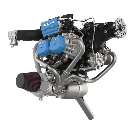
- Page 1 AIRCRAFT ENGINES INSTALLATION MANUAL FOR ROTAX® ENGINE TYPE 915 i A SERIES ref. no.: IM-915 i A | part no.: 898871 picture: ROTAX® 915 iS with options...
- Page 2 GmbH & CO KG, Austria, acc, BGBI 1984 no. 448, and shall not, without prior written permission of BRP-Rotax GmbH & Co KG, be disclosed in whole or in part to third parties. This legend shall be included on any reproduction of these data, in whole or in part. The Manual must remain with the engine/aircraft in case of sale.
- Page 3 BRP-Rotax INSTALLATION MANUAL Table of Content Chapter INTRO – GENERAL NOTE Chapter LEP – LIST OF EFFECTIVE PAGES Chapter TOA – TABLE OF AMENDMENTS Chapter 00–00–00 – GENERAL NOTE Chapter 10–10–00 – STORAGE AND INSTALLATION Chapter 24–00–00 – ELECTRICAL POWER Chapter 61–00–00 –...
- Page 4 BRP-Rotax INSTALLATION MANUAL NOTES Notes Effectivity: 915 i A Series Edition 0/Rev. 0 Page 2 December 01 2017...
- Page 5 If any passages of the manual are not clearly understood or if you have any questions, please contact a ROTAX® authorized distributor or their independent Service Center for ROTAX® aircraft engines. BRP-Rotax GmbH & Co KG (hereinafter “BRP-Rotax“) wishes you much pleasure and satisfaction flying your aircraft powered by this ROTAX®...
- Page 6 BRP-Rotax INSTALLATION MANUAL NOTES Notes Effectivity: 915 i A Series Edition 0/Rev. 0 Page 2 December 01 2017...
-
Page 7: List Of Effective Pages
BRP-Rotax INSTALLATION MANUAL Chapter: LEP LIST OF EFFECTIVE PAGES Chapter Page Date Chapter Page Date Title page December 01 2017 December 01 2017 INTRO December 01 2017 December 01 2017 December 01 2017 December 01 2017 December 01 2017 December 01 2017... - Page 8 BRP-Rotax INSTALLATION MANUAL Chapter Page Date Chapter Page Date December 01 2017 December 01 2017 December 01 2017 December 01 2017 December 01 2017 December 01 2017 December 01 2017 December 01 2017 December 01 2017 December 01 2017 December 01 2017...
- Page 9 BRP-Rotax INSTALLATION MANUAL Chapter Page Date Chapter Page Date December 01 2017 December 01 2017 December 01 2017 December 01 2017 December 01 2017 December 01 2017 78-00-00 December 01 2017 December 01 2017 December 01 2017 December 01 2017...
- Page 10 BRP-Rotax INSTALLATION MANUAL NOTES Notes Effectivity: 915 i A Series Edition 0/Rev. 0 Page 4 December 01 2017...
-
Page 11: Table Of Amendments
BRP-Rotax INSTALLATION MANUAL Chapter: TOA TABLE OF AMENDMENTS Approval* The technical content of this document is approved under the authority of DOA ref. EASA.21.J.048. Cur- Chapter Page Date of change Remark Date of Date of Signature rent approval inclusion approval... - Page 12 BRP-Rotax INSTALLATION MANUAL Summary of amendments Summary of the relevant amendments in this context, but without any claim to completeness. Current Chapter Page Date of change Comment Effectivity: 915 i A Series Edition 0/Rev. 0 Page 2 December 01 2017...
-
Page 13: Table Of Contents
BRP-Rotax INSTALLATION MANUAL Chapter: 00–00–00 GENERAL NOTE TOPICS IN THIS CHAPTER General..............................2 Type description............................3 Scope of supply............................4 Auxiliary equipment (optional) ........................5 Abbreviations and terms .........................6 Conversion table ...........................9 Safety notice ............................10 Safety information ..........................11 Instruction............................13 Technical documentation ........................14 Approval of electric and electronic components (Equipment Qualification according to RTCA/DO- 160) ...............................16... -
Page 14: General
For additional information on engines, its maintenance or parts, you can also contact your nearest ROTAX® authorized Aircraft Engine Distributor or their independent Service Center. ROTAX For ROTAX® Authorized Distributors for aircraft engines see latest Operators Manual or Distributors the official website www.FLYROTAX.com. Engine serial When making inquiries or ordering parts, always indicate the engine serial number. -
Page 15: Type Description
BRP-Rotax INSTALLATION MANUAL TYPE DESCRIPTION The type description consists of the following parts: e. g. ROTAX additional type configuration certification designation Designation Designation Description Type 4-cylinder horizontally opposed, turbocharged engine. Certification Certified to EASA CS-E (TC No.EASA.E.121) Approved to ASTM F2339. -
Page 16: Scope Of Supply
BRP-Rotax INSTALLATION MANUAL SCOPE OF SUPPLY Basic • 4- stroke-, 4 cylinder horizontally opposed-, spark ignition engine, single central cam- shaft push rods —OHV • Liquid cooled cylinder heads • Ram air cooled cylinders • Dry sump forced lubrication • Fully redundant electronic engine management system (EMS) for controlling fuel injec- tion, ignition, etc. -
Page 17: Auxiliary Equipment (Optional)
BRP-Rotax INSTALLATION MANUAL AUXILIARY EQUIPMENT (OPTIONAL) Any equipment not included as part of the standard engine version and thus not a fix com- ponent of the engine is not in the volume of supply. Components especially developed and tested for this engine are readily available at BRP- Rotax. -
Page 18: Abbreviations And Terms
BRP-Rotax INSTALLATION MANUAL ABBREVIATIONS AND TERMS Abbreviations Description Reference to another section � center of gravity The drop symbol indicates use of sealing agents, adhesives or lubri- cants (only in the Illustrated Parts Catalog). °C Degrees Celsius (Centigrade) °F Degrees Fahrenheit... - Page 19 HIC B Harness Interface Connector B Instrument Flight Rules INJ 1–8 Injector 1–8 Illustrated Parts Catalog inch per second iRMT independent ROTAX Maintenance Training International Standard Atmosphere Kilograms KNOCK Knock sensor MAPS 1+2 Manifold Air Pressure Sensor 1+2 MATS 1+2...
- Page 20 Production Organisation Approval PTFE Polytetrafluoroethylene Power Take Off Rev. Revision ROTAX® is a trademark of BRP-Rotax GmbH & Co KG Research Octane Number RON 424 ROTAX® Norm 424 s.v. still valid (only Illustrated Parts Catalog) Serial Number Society of Automotive Engineers...
-
Page 21: Conversion Table
BRP-Rotax INSTALLATION MANUAL Maintenance Manual XXXX shows the serial component number CONVERSION TABLE Units of length: Units of power: 1 mm = 0.03937 in 1 kW = 1.341 hp 1 in = 25.4 mm 1 hp = 0.7457 kW 1 ft = 12 in 1 kW = 1.3596 PS... -
Page 22: Safety Notice
The information and descriptions of components and systems contained in this Manual are correct at the time of publication. BRP-Rotax maintains a policy of continuous im- provement of its products without imposing upon itself any obligation to retrofit products previously manufactured. -
Page 23: Safety Information
• Due to the varying designs, equipment and types of aircraft, BRP-Rotax grants no war- ranty on the suitability of its engines use on any particular aircraft. Further, BRP-Rotax... - Page 24 BRP-Rotax INSTALLATION MANUAL Engine operation • The engine must always be operated according to the content of the latest Operators Manual • To eliminate the risk of injury or damage, ensure any loose equipment or tools are prop- erly secured before starting the engine •...
-
Page 25: Instruction
Spare parts must meet the requirements defined by the engine manufacturer.This can only be guaranteed when using GENUINE-ROTAX®-spare parts and/or accessories (see IPC). Spare parts are available at ROTAX® Authorized Distributors and their inde- pendent Service Centers. Any warranty by BRP-Rotax will become void if other spare parts and or accessories than GENUINE-ROTAX®-spare parts and/or accessories are... -
Page 26: Technical Documentation
BRP-Rotax INSTALLATION MANUAL TECHNICAL DOCUMENTATION These documents form the instructions ensuring continued airworthiness of ROTAX® air- craft engines. The information contained herein is based on data and experience that are considered ap- plicable for authorized mechanics (iRMT, see Maintenance Manual Line) under normal conditions for engine removal and installation. - Page 27 Installation drawings and a DMU-model for (virtual) installation analysis are available from drawings the ROTAX® Authorized Distributors or their independent Service Centers on special re- quest and relevant non disclosure and copyright regulations. The illustrations in this Manual shows a possible installation variant included non certified parts.
-
Page 28: Approval Of Electric And Electronic Components (Equipment Qualification According To Rtca/Do-160)
BRP-Rotax INSTALLATION MANUAL APPROVAL OF ELECTRIC AND ELECTRONIC COMPONENTS (EQUIPMENT QUALIFICATION ACCORDING TO RTCA/DO-160) RTCA/DO-160 defines a series of minimum standard environmental test conditions and applicable test procedures for airborne equipment. The purpose of these tests is to pro- vide a laboratory means of determining the performance characteristics of airborne equip- ment in environmental conditions representative of those which may be encountered in airborne operation of the equipment. - Page 29 BRP-Rotax INSTALLATION MANUAL DO-160G, Section 24 — Icing Test not performed DO-160G, Section 25 — Electrostatic Discharge Cat. A Component tem- peratures limits System Limit Min. Max. - 40 °C (- 40 °F) 80 °C (176 °F) EGT Sensors (electronic - 40 °C (- 40 °F)
- Page 30 BRP-Rotax INSTALLATION MANUAL NOTES Notes Effectivity: 915 i A Series Edition 0/Rev. 0 Page 18 December 01 2017...
- Page 31 BRP-Rotax INSTALLATION MANUAL Chapter: 10–10–00 STORAGE AND INSTALLATION TOPICS IN THIS CHAPTER Special tools............................3 General..............................4 Engine storage............................4 Unpacking the engine ..........................4 Engine handling ............................7 Effectivity: 915 i A Series 10–10–00 Edition 0/Rev. 0 Page 1 December 01 2017...
- Page 32 BRP-Rotax INSTALLATION MANUAL Figure 2.1: 915 iS engine 10–10–00 Effectivity: 915 i A Series Edition 0/Rev. 0 Page 2 December 01 2017...
-
Page 33: Special Tools
BRP-Rotax INSTALLATION MANUAL SPECIAL TOOLS Description Part number Engine lift set 876040 Effectivity: 915 i A Series 10–10–00 Edition 0/Rev. 0 Page 3 December 01 2017... -
Page 34: General
ENGINE STORAGE The engine is preserved at BRP-Rotax thus guaranteeing proper protection against corro- sion damage for at least 12 months after the date of delivery from BRP-Rotax. This warranty is subject to the following conditions: • The engine must be stored in the GENUINE-ROTAX®-packing as supplied by BRP- Rotax. - Page 35 BRP-Rotax INSTALLATION MANUAL If the serial number or the engine type is deviating from the delivery contact a ROTAX® Au- thorized Distributor- or their independent Service Center for ROTAX® aircraft engines. 4. Check the engine for damage or corrosion. If the engine is damaged or corroded, contact a ROTAX® Authorized Distributor- or their in- dependent Service Center for ROTAX®...
- Page 36 BRP-Rotax INSTALLATION MANUAL Figure 2.2: Protective covering positions Exhaust pipe Fuel (outlet) /fuel pressure regulator Fuel rail (inlet) Oil inlet/outlet and oil return turbo Throttle body socket assy. Coolant inlet/outlet Air intake socket on turbocharger Wastegate Propeller shaft Cover (governor flange) 10–10–00...
-
Page 37: Engine Handling
Attachment The engine may only be lifted on the dedicated attachment points by using the GENUINE- points ROTAX®- engine lift set. Make sure that lifting device does not bend the attachment lugs by relevant force distribution. Figure 2.3: Attachment points Effectivity: 915 i A Series 10–10–00... - Page 38 BRP-Rotax INSTALLATION MANUAL NOTES Notes Effectivity: 915 i A Series Edition 0/Rev. 0 Page 8 December 01 2017...
- Page 39 BRP-Rotax INSTALLATION MANUAL Chapter: 24–00–00 ELECTRICAL POWER TOPICS IN THIS CHAPTER System description ..........................3 System limitations ..........................3 Interface description ..........................4 Interface overview ..........................4 Electrical interfaces ..........................4 Mechanical interfaces ..........................9 Installation notes...........................10 Installation overview ..........................10 Grounding cables ..........................10 Battery..............................11 Control elements ..........................12 Validation of installation ........................13...
- Page 40 BRP-Rotax INSTALLATION MANUAL Figure 3.1: Internal power supply 24–00–00 Effectivity: 915 i A Series Edition 0/Rev. 0 Page 2 December 01 2017...
-
Page 41: System Description
BRP-Rotax INSTALLATION MANUAL SYSTEM DESCRIPTION For a detailed system description refer to the latest issue of the Operators Manual. SYSTEM LIMITATIONS ATTENTION Under no circumstances consumer cables must be routed alongside the ignition cables. There is a risk of electromagnetic interference. -
Page 42: Interface Description
BRP-Rotax INSTALLATION MANUAL INTERFACE DESCRIPTION INTERFACE OVERVIEW Figure 3.3: Fusebox connections X1 Connector (electrical X2 Connector (electrical interface) interface) X3 Connector (electrical. Regulator Plate A (electrical interface) interface) Regulator Plate B (electrical Fusebox mounting points (me- interface) chanical interface) ELECTRICAL INTERFACES... - Page 43 BRP-Rotax INSTALLATION MANUAL Figure 3.4: X3-Connector: Fusebox side Terminal 1 Terminal 2 Terminal 3 Terminal 1 enables to supply the EMS with an external power source (e.g. in case the in- ternal power supply fails supplying the EMS). Terminal 2 enables powering the EMS dur- ing engine start (until the engine speed is high enough that the internal generator is able to supply the EMS).
- Page 44 BRP-Rotax INSTALLATION MANUAL ATTENTION In failure conditions the output voltage can exceed the specified limits. The following measurement is taken at an oil temperature of 135 °C (275 °F). Figure 3.5: Characteristic curve of internal generators 24–00–00 Effectivity: 915 i A Series Edition 0/Rev.
- Page 45 BRP-Rotax INSTALLATION MANUAL Fusebox Regula- The regulator plate A needs to be connected with the EMS Ground (cable lugs on the (en- tor A gine-) wiring harness). The terminal is conducted as a M4 screw connection suitable for cable lug according to DIN 46225 (tightening torque: 1.2 Nm). The cable lugs need to be evenly spread onto the three available terminals.
- Page 46 BRP-Rotax INSTALLATION MANUAL Fusebox Regula- The Regulator B needs to be connected with the Airframe Ground. The terminal is con- tor B ducted as a M6 screw connection suitable for cable lug according to DIN 46225 (tightening torque: 5.9 Nm).
-
Page 47: Mechanical Interfaces
BRP-Rotax INSTALLATION MANUAL MECHANICAL INTERFACES Fusebox mount- ing points Figure 3.8: Fusebox –Connections and dimensions Effectivity: 915 i A Series 24–00–00 Edition 0/Rev. 0 Page 9 December 01 2017... -
Page 48: Installation Notes
BRP-Rotax INSTALLATION MANUAL INSTALLATION NOTES General The representation of components in this chapter which are not scope of the delivery is only symbolic. The design shown in this chapter does not represent a specified execution but should support the understanding of the system. -
Page 49: Battery
BRP-Rotax INSTALLATION MANUAL When the engine is running or when the engine is turned off ( and the Fusebox is not sup- plied with external power), the EMS circuit works isolated from the rest of the aircraft. Therefore following components need to be installed decoupled from the airframe ground: •... -
Page 50: Control Elements
BRP-Rotax INSTALLATION MANUAL Interface Min. Max. Nominal Parameter Cold Cranking 350 A at -18 °C Ampere (-0.4 °F) (SAE J537) Capacity 16 Ah The usage of a battery with lower capacity may have a negative impact on the starting be- havior of the engine. -
Page 51: Validation Of Installation
BRP-Rotax INSTALLATION MANUAL VALIDATION OF INSTALLATION General The validation procedures described in this chapter do not claim to be complete. The cor- rect execution and compliance with all given system limitations and interface descriptions as well as with standards and norms given by authorities must be proven by the aircraft manufacturer. - Page 52 BRP-Rotax INSTALLATION MANUAL Figure 3.10: Validation of EMS and Airframe Circuit separation Rectifier regulator A (black connector) Multimeter Rectifier regulator B (grey connector) In case of continuity the installation is not sufficient and the wiring concept needs to be revised.
- Page 53 BRP-Rotax INSTALLATION MANUAL Chapter: 61–00–00 PROPELLER DRIVE TOPICS IN THIS CHAPTER System description ..........................3 System limitations ..........................3 Interface description ..........................4 Interface overview ..........................4 Mechanical interfaces ..........................5 Hydraulic governor for constant speed propeller ..................7 Effectivity: 915 i A Series 61–00–00 Edition 0/Rev. 0...
- Page 54 BRP-Rotax INSTALLATION MANUAL Figure 4.1: Propeller drive 61–00–00 Effectivity: 915 i A Series Edition 0/Rev. 0 Page 2 December 01 2017...
-
Page 55: System Description
BRP-Rotax INSTALLATION MANUAL SYSTEM DESCRIPTION For a detailed System description refer to the latest issue of the Operators Manual. SYSTEM LIMITATIONS Operating limits Refer to latest issue of the Operators Manual. Moment of inertia Min. Max. System Limit Moment of inertia on propeller 1500 kg cm (3.559 lb ft... -
Page 56: Interface Description
BRP-Rotax INSTALLATION MANUAL INTERFACE DESCRIPTION INTERFACE OVERVIEW Figure 4.2: Interface Propeller shaft (mechanical. Interface) Governor flange (hydraulic. Interface) N N O O T T E E The cover used for delivery needs to be removed before engine operation. The cover may not be used in operational condition. -
Page 57: Mechanical Interfaces
BRP-Rotax INSTALLATION MANUAL MECHANICAL INTERFACES Propeller shaft The propeller in tractor or pusher arrangement must be fitted on the propeller flange in ac- flange cordance with applicable regulations. As required utilize one of three possible pitch circle diameters (P.C.D.) on the flange. - Page 58 BRP-Rotax INSTALLATION MANUAL Figure 4.4: Direction of rotation 61–00–00 Effectivity: 915 i A Series Edition 0/Rev. 0 Page 6 December 01 2017...
-
Page 59: Hydraulic Governor For Constant Speed Propeller
BRP-Rotax INSTALLATION MANUAL HYDRAULIC GOVERNOR FOR CONSTANT SPEED PROPELLER Figure 4.5: Crankcase flange Pressure oil line assy. Governor flange Oil inlet Oil outlet Effectivity: 915 i A Series 61–00–00 Edition 0/Rev. 0 Page 7 December 01 2017... - Page 60 BRP-Rotax INSTALLATION MANUAL Drive Drive via propeller gearbox. Position of the propeller connection on the governor flange: x-axis [mm/in] y-axis [mm/in] z-axis [mm/in] -206.3 (-8.12) 51.5 (2.03) Connection ATTENTION Obey the manufacturers instructions! Technical Data Gear ratio from crankshaft to hydraulic governor is 1.842, i.e. the propeller governor runs at 0.54 times engine speed.
- Page 61 BRP-Rotax INSTALLATION MANUAL Chapter: 72–00–00 ENGINE TOPICS IN THIS CHAPTER System description ..........................3 System limitations ..........................6 Interface description ..........................9 Interface overview ..........................9 Mechanical interfaces ..........................9 Installation notes........................... 11 Engine suspension ..........................11 Effectivity: 915 i A Series 72–00–00 Edition 0/Rev. 0...
- Page 62 BRP-Rotax INSTALLATION MANUAL Figure 5.1: Engine 72–00–00 Effectivity: 915 i A Series Edition 0/Rev. 0 Page 2 December 01 2017...
-
Page 63: System Description
BRP-Rotax INSTALLATION MANUAL SYSTEM DESCRIPTION For a detailed System description refer to the latest issue of the Operators Manual. Figure 5.2: Engine side view Engine number Propeller flange Connection for return line, both sides Propeller gearbox mandatory Attachment points (for engine transport) - Page 64 BRP-Rotax INSTALLATION MANUAL Figure 5.3: Engine Front view Oil pump Oil filter Exhaust flange Muffler assy. Fuel line assy. Crankshaft locking screw position Connection for Turbo oil line return 72–00–00 Effectivity: 915 i A Series Edition 0/Rev. 0 Page 4...
- Page 65 BRP-Rotax INSTALLATION MANUAL Figure 5.4: Top view Throttle valve support assy. Airbox Dual ignition coils Expansion tank assy. Fuel rail (right, left) POP OFF valve Inter cooler Connection for fuel feed line Connection for fuel Attachment points (for engine transport)
-
Page 66: System Limitations
BRP-Rotax INSTALLATION MANUAL Figure 5.5: Rear view Ignition housing Electric starter Water pump housing Engine suspension frame (ring mount) Turbocharger assy. Solenoid valve (PCV) Fuel pressure regulator SYSTEM LIMITATIONS Operating limits Refer to latest issue of the Operators Manual. Installation... - Page 67 BRP-Rotax INSTALLATION MANUAL Figure 5.6: Bank angle Angle/force Description ɑ Bank or rotation Gravity Attachment For mounting the engine on the engine suspension, R2, R3, L3 and L2 of attachment points points must be used. All used screws must not be touch engine components.
- Page 68 BRP-Rotax INSTALLATION MANUAL Figure 5.7: Propeller and vertical axis Propeller axis The y1-axis must be perpendicular to the longitudinal axis of the aircraft. Min. Max. System Limit Permissible deviation from - 10° + 10° perpendicular (α) 72–00–00 Effectivity: 915 i A Series Edition 0/Rev.
-
Page 69: Interface Description
BRP-Rotax INSTALLATION MANUAL INTERFACE DESCRIPTION INTERFACE OVERVIEW Figure 5.8: Attachment points MECHANICAL INTERFACES Attachment Interface Parameter Value points Attachment points x-axis (in) 615 mm (24.21 in.) 105 mm -105 mm -105 mm -105 mm y-axis (in) (-4.13 in.) (-4.13 in.) (-4.13 in.) - Page 70 BRP-Rotax INSTALLATION MANUAL Weight Engine component Weight Base engine with gearbox: 74.23 kg (173.5 lb) Cooling air baffle 0.38 kg (0.838 lb) 0.35 kg (0.771 lb) Oil tank 1.50 kg (3.31 lb) Intercooler 1.65 kg (3.65 lb) 1.13 kg (2.49 lb) Fusebox 2.02 kg (4.45 lb)
-
Page 71: Installation Notes
BRP-Rotax INSTALLATION MANUAL INSTALLATION NOTES General The representation of components in this chapter which are not scope of the delivery is only symbolic. The design shown in this chapter does not represent a specified execution but should support the understanding of the system. - Page 72 The hex. screws M10x60 on the attachment points R2 and L2 are only used for transport securing but must never be utilized for engine suspension. See inter- face overview.Therefore use the ROTAX engine suspension frame and the 4 stated attachment points R2, L2, R3, L3.
- Page 73 BRP-Rotax INSTALLATION MANUAL Chapter: 72–60–00 AIR INTAKE SYSTEM TOPICS IN THIS CHAPTER System description ..........................3 System limitations ..........................3 Interface description ..........................5 Interface overview ..........................5 Mechanical interfaces ..........................6 Pneumatic interfaces ..........................7 Electrical interfaces ..........................8 Installation notes.............................9 Installation overview ..........................9 Effectivity: 915 i A Series 72–60–00...
- Page 74 BRP-Rotax INSTALLATION MANUAL Figure 6.1: Air intake system 72–60–00 Effectivity: 915 i A Series Edition 0/Rev. 0 Page 2 December 01 2017...
-
Page 75: System Description
BRP-Rotax INSTALLATION MANUAL SYSTEM DESCRIPTION For a detailed System description refer to the latest issue of the Operators Manual. SYSTEM LIMITATIONS Air intake Following requirements may be used: System Limit Min. Max. Flow rate 400 kg/h Pressure loss (between ambi-... - Page 76 BRP-Rotax INSTALLATION MANUAL m WARNING Non-compliance can result in serious injuries or death! With throttle lever not connected the throttle valve will remain fully open. The starting position of the throttle valve is therefore full throttle! Therefore never start the engine without connecting the throttle lever first.
-
Page 77: Interface Description
BRP-Rotax INSTALLATION MANUAL INTERFACE DESCRIPTION INTERFACE OVERVIEW Interface overview Figure 6.2: Air intake: Interface overview and components Turbocharger inlet (pneumatic Overboost valve to throttle Interface) Turbocharger Intercooler Throttle body (mechanical interface) Overboost valve Pressure control valve (electrical Wastegate (boost pressure valve) -
Page 78: Mechanical Interfaces
BRP-Rotax INSTALLATION MANUAL MECHANICAL INTERFACES Throttle body Interface Parameter Min. Max. — Tightening torque 4 Nm (3.32 lb ft.) (suitable for flexible cable), 1.5 mm (0.06 in.) steel rope or sin- gle-strand wire — Cable travel 65 mm (2.56 in.) Actuating force 7.5 N (1.69 lb ft.) -
Page 79: Pneumatic Interfaces
BRP-Rotax INSTALLATION MANUAL ATTENTION Make sure proper dampening of the 4 fixation points and assure stressfree instal- lation on these 4 fixation points. PNEUMATIC INTERFACES Airfilter See figure Connection on turbocharger connection Interface Parameter Min. Max. Slip-on length 30 mm (1.18 in.) N N O O T T E E Use only filter elements which will not tend to restrict the flow when in contact with water. -
Page 80: Electrical Interfaces
BRP-Rotax INSTALLATION MANUAL Connection on intercooler: Interface Parameter Min. Max. Slip-on length 32 mm (1.26 in.) Figure 6.3: Intercooler: Connection and dimensions Intercooler to Interface Parameter Min. Max. overboost valve Slip-on length 18 mm (0.71 in.) Figure 6.5: Overboost valve Connection on throttle body: Install the delivered hose (scope of supply) to the correct side of the overboost valve, recheck if it fits. -
Page 81: Installation Notes
BRP-Rotax INSTALLATION MANUAL INSTALLATION NOTES General The representation of components in this chapter which are not scope of the delivery is only symbolic. The design shown in this chapter does not represent a specified execution but should support the understanding of the system. - Page 82 BRP-Rotax INSTALLATION MANUAL NOTES Notes Effectivity: 915 i A Series Edition 0/Rev. 0 Page 10 December 01 2017...
- Page 83 BRP-Rotax INSTALLATION MANUAL Chapter: 73–00–00 ENGINE – FUEL AND CONTROL TOPICS IN THIS CHAPTER System Description ..........................3 System limitations ..........................3 Interface description ..........................4 Interface overview ..........................4 Hydraulic interfaces ..........................5 Electrical interfaces ..........................5 Mechanical interfaces ..........................6 Installation notes.............................7 Installation overview ..........................8 Fuel lines ..............................9...
- Page 84 BRP-Rotax INSTALLATION MANUAL Figure 7.1: Fuel System 73–00–00 Effectivity: 915 i A Series Edition 0/Rev. 0 Page 2 December 01 2017...
-
Page 85: System Description
BRP-Rotax INSTALLATION MANUAL SYSTEM DESCRIPTION For a detailed System description refer to the latest issue of the Operators Manual. SYSTEM LIMITATIONS Operating limits Refer to latest issue of the Operators Manual. Effectivity: 915 i A Series 73–00–00 Edition 0/Rev. 0... -
Page 86: Interface Description
BRP-Rotax INSTALLATION MANUAL INTERFACE DESCRIPTION INTERFACE OVERVIEW Figure 7.2: Fuel System: Interface overview and components Fuel rail 2/4 outlet line (hydraulic Fuel rail 1/3 feed line (hydraulic Interface) Interface) Fuel hose assy. Fuel rail Fuel pump connectors (electrical Injection valves... -
Page 87: Hydraulic Interfaces
BRP-Rotax INSTALLATION MANUAL HYDRAULIC INTERFACES Fuel inlet Min. Max. Interface Parameter Fuel pressure (relative to MAP) 2.9 bar (42 psi) 3.1 bar (45 psi) Acceptable Fuel pressure 2.5 bar (36 psi) 3.5 bar (51 psi) exceedance (max. 3 sec.) N N O O T T E E... -
Page 88: Mechanical Interfaces
BRP-Rotax INSTALLATION MANUAL MECHANICAL INTERFACES Banjo bolt Standard banjo bolt can be replaced by an optional Sensor adapter for connectivity di- adapter rectly on the fuel inlet of the fuel pressure regulator. Interface Parameter Min. Max. Tightening torque 23 Nm (17 ft. lb) 27 Nm (20 ft.lb) -
Page 89: Installation Notes
BRP-Rotax INSTALLATION MANUAL INSTALLATION NOTES General The representation of components in this chapter which are not scope of the delivery is only symbolic. The design shown in this chapter does not represent a specified execution but should support the understanding of the system. -
Page 90: Installation Overview
BRP-Rotax INSTALLATION MANUAL INSTALLATION OVERVIEW Figure 7.3: Fuel system Fuel pump 1 Fuel tank Fuel pump 2 Fine filter Fuel pressure regulator Coarse filter/water trap 73–00–00 Effectivity: 915 i A Series Edition 0/Rev. 0 Page 8 December 01 2017... -
Page 91: Fuel Lines
BRP-Rotax INSTALLATION MANUAL FUEL LINES To prevent problems with vapour lock, all the fuel lines should be insulated against heat in the engine compartment. It is recommended to route the fuel lines in an appropriate dis- tance from hot engine components and avoid sharp bends. -
Page 92: Coarse Filter
BRP-Rotax INSTALLATION MANUAL N N O O T T E E The switching between several fuel tanks at power loss due to fuel shortage should be given within a defined period of time and without falling below the mini- mum performance limit and must be ensured by the aircraft manufacturer. Refer to the latest requirements such as FAR or EASA. -
Page 93: Fuel Pump
BRP-Rotax INSTALLATION MANUAL ATTENTION An installation without fine filter may have a significant impact on the proper functional- ity of this engine. FUEL PUMP For reducing the risk of vapor lock, the fuel pump should be placed in a good ventilated area. -
Page 94: Fuel Shut Off Valve
BRP-Rotax INSTALLATION MANUAL • A header tank design that enables the re-entry of vapour bubbles in the suction line • Multi tank system without catch-, header tank FUEL SHUT OFF VALVE The fuel shut off valve position on the pressure side of the fuel system (after the fuel pump module) can have an unfavorable impact on the installation of the 915 i. - Page 95 BRP-Rotax INSTALLATION MANUAL Chapter: 75–00–00 COOLING SYSTEM TOPICS IN THIS CHAPTER System Description ..........................3 System limitations ..........................3 Interface description ..........................4 Interface overview ..........................4 Hydraulic interfaces ..........................5 Air Cooling interfaces..........................7 Installation notes.............................9 Installation overview ..........................9 Water inlet elbow ...........................9 Expansion tank ...........................10 Coolant hoses .............................10...
- Page 96 BRP-Rotax INSTALLATION MANUAL Figure 8.1: Cooling System 75–00–00 Effectivity: 915 i A Series Edition 0/Rev. 0 Page 2 December 01 2017...
-
Page 97: System Description
BRP-Rotax INSTALLATION MANUAL SYSTEM DESCRIPTION For a detailed System description refer to the latest issue of the Operators Manual. SYSTEM LIMITATIONS Operating limits Refer to latest issue of the Operators Manual. m WARNING Non-compliance can result in serious injuries or death! The cooling system must be designed so that operating temperatures will not exceed the maximum values. -
Page 98: Interface Description
BRP-Rotax INSTALLATION MANUAL INTERFACE DESCRIPTION INTERFACE OVERVIEW Figure 8.2: Cooling System – Interfaces Water pump housing Coolant hose Expansion tank Radiator cap Expansion tank connection (hy- Water inlet elbow (hydraulic draulic Interface) Interface) Water outlet (hydraulic Coolant temperature sensor Interface) Cooling air baffle 75–00–00... -
Page 99: Hydraulic Interfaces
BRP-Rotax INSTALLATION MANUAL HYDRAULIC INTERFACES Water inlet elbow Interface Parameter Min. Max. Cooling system pressure (relative) 1.6 bar (232 psi) Cooling water temperature - 20 °C (- 4 °F) 125 °C (257 °F) Cooling water flow (at 5800 rpm) 70 l/h Slip on length 19 mm (0.75 in) - Page 100 BRP-Rotax INSTALLATION MANUAL Expansion tank Interface Parameter Min. Max. connection Slip on length 18 mm Figure 8.4: Expansion tank connection 75–00–00 Effectivity: 915 i A Series Edition 0/Rev. 0 Page 6 December 01 2017...
-
Page 101: Air Cooling Interfaces
BRP-Rotax INSTALLATION MANUAL AIR COOLING INTERFACES Cooling air baffle Figure 8.5: Cooling air baffle position Position x-axis y-axis z-axis - 142 mm (- 5.59 in.) - 101 mm (- 3.98 in.) - 106 mm (- 4.17 in.) Cooling air baffle... - Page 102 BRP-Rotax INSTALLATION MANUAL Figure 8.6: Cooling air baffle for tractor 75–00–00 Effectivity: 915 i A Series Edition 0/Rev. 0 Page 8 December 01 2017...
-
Page 103: Installation Notes
BRP-Rotax INSTALLATION MANUAL INSTALLATION NOTES General The representation of components in this chapter which are not scope of the delivery is only symbolic. The design shown in this chapter does not represent a specified execution but should support the understanding of the system. -
Page 104: Expansion Tank
BRP-Rotax INSTALLATION MANUAL Figure 8.8: Water inlet elbow Water pump housing Water inlet elbow Use two M6x20 Allen screws lock washers to attach the water inlet elbow. Tighten screws to 10 Nm (90 in lb.) ATTENTION The total slip-on length of the water inlet elbow and expansion tank should be used. -
Page 105: Coolant
BRP-Rotax INSTALLATION MANUAL Aluminium tubes with an inner diameter of 25 mm (0.98 in) can be used instead of longer hoses. These should have a bulge (1) in order to prevent coolant hoses working loose. Note as well that this will double the number of hose clips required. -
Page 106: Validation Of Installation
BRP-Rotax INSTALLATION MANUAL VALIDATION OF INSTALLATION General The validation procedures described in this chapter do not claim to be complete. The cor- rect execution and compliance with all given system limitations and interface descriptions as well as with standards and norms given by authorities must be proven by the aircraft manufacturer. - Page 107 BRP-Rotax INSTALLATION MANUAL Measuring point Figure 8.11: Measuring point Pressure test To ensure the System has no leakage, remove the pressure cap from the expansion tank. Then attach the pressure tester and pump the system until the pressure manometer shows 1.2 bar (18 psi). After min. 1 minute, there should be still 1.2 bar (18 psi) pressure in the system.
- Page 108 BRP-Rotax INSTALLATION MANUAL NOTES Notes Effectivity: 915 i A Series Edition 0/Rev. 0 Page 14 December 01 2017...
- Page 109 BRP-Rotax INSTALLATION MANUAL Chapter: 76–00–00 ENGINE CONTROLS TOPICS IN THIS CHAPTER Special tools............................3 System description ..........................4 System limitations ..........................4 Interface description ..........................5 Interface overview ..........................5 Electrical interfaces ..........................5 Mechanical interfaces ..........................10 Installation notes...........................12 Installation overview ..........................12 LANE Select Switches .........................13 Fuel pump switches ..........................14...
- Page 110 BRP-Rotax INSTALLATION MANUAL Figure 9.1: Engine management system (EMS) 76–00–00 Effectivity: 915 i A Series Edition 0/Rev. 0 Page 2 December 01 2017...
-
Page 111: Special Tools
BRP-Rotax INSTALLATION MANUAL SPECIAL TOOLS Description Part number n.a. Crimping pliers MOLEX 64016-0035/63811-4400 n.a. Disassembly tool MOLEX 63813-1500 Effectivity: 915 i A Series 76–00–00 Edition 0/Rev. 0 Page 3 December 01 2017... -
Page 112: System Description
BRP-Rotax INSTALLATION MANUAL SYSTEM DESCRIPTION For a detailed System description refer to the latest issue of the Operators Manual. SYSTEM LIMITATIONS Operating limits Refer to latest issue of the Operators Manual. Valid installation The ECU may be installed either in the engine compartment or in the cockpit. To prevent... -
Page 113: Interface Description
BRP-Rotax INSTALLATION MANUAL INTERFACE DESCRIPTION INTERFACE OVERVIEW Figure 9.2: Engine Management System (EMS)– Interfaces Harness Interface Connector A Harness Interface Connector B (HIC A) (electrical Interface) (HIC B) (electrical Interface) X1 Connector (electrical X2 Connector (electrical Interface) Interface) ECU (electrical, mechanical... - Page 114 BRP-Rotax INSTALLATION MANUAL Figure 9.3: HIC A Connector In case the EMS is powered by an external power source or by one of the internal generators: • A connection between Terminal 1 and Terminal 7 will power ECU Lane A •...
- Page 115 BRP-Rotax INSTALLATION MANUAL Terminal (Supply) Terminal (Ground) Interface Min. Max. Nomi- Parameter 1 LANE_SEL_ 7 LANE_SEL_SW_ Nominal 12 V SW_A_1 Voltage Nominal 7.5 A Current 3 SIG_FUEL_ 9 GND_FUEL_ Nominal 12 V PUMP_1 PUMP_1 Voltage Nominal 10 A Current Harness Interface Connector B Figure 9.5: HIC B connector...
- Page 116 BRP-Rotax INSTALLATION MANUAL Figure 9.6: HIC B Connector – Engine controls Terminal (Supply) Terminal (Ground) Interface Parameter min- LANE_SEL_SW_ LANE_SEL_SW_B_2 Nominal 12 V Voltage Nominal Current 11 GND_FUEL_PUMP_ SIG_FUEL_ Nominal 12 V PUMP_2 Voltage Nominal Current 12 SUPP_START_ Nominal 12 V...
- Page 117 BRP-Rotax INSTALLATION MANUAL Wiring harness grounding ATTENTION The grounding cable must be attached to airframe ground. Fuel pump See Chapter 73–00–00 section Interface Description Effectivity: 915 i A Series 76–00–00 Edition 0/Rev. 0 Page 9 December 01 2017...
-
Page 118: Mechanical Interfaces
BRP-Rotax INSTALLATION MANUAL MECHANICAL INTERFACES Engine Control Unit (ECU) Figure 9.7: ECU –mounting points Connector socket A1 Connector socket A2 Connector socket B 76–00–00 Effectivity: 915 i A Series Edition 0/Rev. 0 Page 10 December 01 2017... - Page 119 BRP-Rotax INSTALLATION MANUAL Sensors Ambient Air Pressure and Temperature Sensors (AAPTS 1, 2) Figure 9.8: AAPTS – mounting points Maximal diameter of screw in the interior of the mounting hole: 6 mm (0.24 in). Only mount sensor with a washer (Ø 10 mm (0.39 in) or with an adequate screw head diameter. The maximum permissible pressure at the mounting flange may not exceed 20 N/m (0.0029...
-
Page 120: Installation Notes
BRP-Rotax INSTALLATION MANUAL INSTALLATION NOTES General The representation of components in this chapter which are not scope of the delivery is only symbolic. The design shown in this chapter does not represent a specified execution but should support the understanding of the system. -
Page 121: Lane Select Switches
BRP-Rotax INSTALLATION MANUAL Figure 9.10: Harness Interface Connector B-Schematic Part Function Harness Interface Connector B Lane Select Switch B (-S5) Start Button (-S6) LANE SELECT SWITCHES Lane Select Interface Parameter Value Switch A (-S4) Switch type Toggle (normally open) Nominal voltage... -
Page 122: Fuel Pump Switches
BRP-Rotax INSTALLATION MANUAL Interface Parameter Value Nominal current 7.5 A Number of poles 1-pole FUEL PUMP SWITCHES Fuel pump Interface Parameter Value switch 1 (-S7) Switch type Toggle (normally open) Nominal voltage 28 V Nominal current 10 A Number of poles... - Page 123 BRP-Rotax INSTALLATION MANUAL Chapter: 77–00–00 ENGINE INDICATING TOPICS IN THIS CHAPTER System description ..........................3 System limitations ..........................3 Interface description ..........................4 Interface overview ..........................4 Electrical interfaces ..........................4 Installation notes.............................8 Installation overview ..........................8 Warning lamps ............................10 CAN interfaces............................10 Effectivity: 915 i A Series 77–00–00...
- Page 124 BRP-Rotax INSTALLATION MANUAL Figure 10.1: Engine indication 77–00–00 Effectivity: 915 i A Series Edition 0/Rev. 0 Page 2 December 01 2017...
-
Page 125: System Description
BRP-Rotax INSTALLATION MANUAL SYSTEM DESCRIPTION The complete system is volume of supply and is certified together with the engine. For a detailed system description refer to latest issue of the Operators Manual. SYSTEM LIMITATIONS Maintenance CAN The Maintenance CAN must only be used in combination with a B.U.D.S. Aircraft USB-to- CAN converter and B.U.D.S. -
Page 126: Interface Description
BRP-Rotax INSTALLATION MANUAL INTERFACE DESCRIPTION INTERFACE OVERVIEW Figure 10.2: Engine Management System (EMS) – Interfaces Harness Interface Connector A Harness Interface Connector B (HIC A) (HIC B) Electromagnetic shielding of CAN Bus ELECTRICAL INTERFACES Harness Interface The HIC Connector A is equipped with a Maintenance CAN interface, a Display CAN inter-... - Page 127 The HIC Connectors must be mounted according to the procedure prescribed in Chapter 76-00-00. The Display CAN is based on the CAN Aerospace protocol. For detailed interface descrip- tion contact an authorized ROTAX® Distributor or its independent Service Center. Effectivity: 915 i A Series 77–00–00 Edition 0/Rev.
- Page 128 BRP-Rotax INSTALLATION MANUAL Harness Interface The HIC Connector B is equipped with a Maintenance CAN interface, a Display CAN inter- Connector B face and terminals which can be used to actuate a warning lamp indicating the current sta- tus of the ECU Lane B. Interfaces to control elements are described in Chapter 76-00-00.
- Page 129 76-00-00. The Display CAN is based on the CAN Aerospace protocol. For detailed interface descrip- tion contact an authorized ROTAX® Distributor or its independent Service Center. Electromagnetic The electromagnetic CAN Bus shielding lugs need to be connected with the Airframe shielding of CAN Ground.
-
Page 130: Installation Notes
BRP-Rotax INSTALLATION MANUAL INSTALLATION NOTES General The representation of components in this chapter which are not scope of the delivery is only symbolic. The design shown in this chapter does not represent a specified execution but should support the understanding of the system. - Page 131 BRP-Rotax INSTALLATION MANUAL Part Function Display CAN A Maintenance CAN A Figure 10.6: Harness Interface Connector B-Schematic Part Function Harness Interface Connector B Warning Lamp B (-H2) Warning Lamp B (LED) (-H2 V2) Resistor 1.5 kΩ (-F8) Resistor 1 kΩ (-F9)
- Page 132 BRP-Rotax INSTALLATION MANUAL WARNING LAMPS Warning Lamp A, Value Interface Parameter B (-H1, -H2) Nominal voltage Nominal current max. 120 mA Instead of common lamps also LED lamps (-H1 V2, -H2 V2) can be used. In this case a appropriate pre-resistor must be conducted serial to the LED. An additional resistor paral- lel to the LED avoids that the ECU detects an open circuit at this warning lamp.
- Page 133 BRP-Rotax INSTALLATION MANUAL Chapter: 78–00–00 EXHAUST SYSTEM TOPICS IN THIS CHAPTER System description ..........................3 System limitations ..........................3 Interface description ..........................4 Interface overview ..........................4 Mechanical interfaces ..........................5 Effectivity: 915 i A Series 78–00–00 Edition 0/Rev. 0 Page 1 December 01 2017...
- Page 134 BRP-Rotax INSTALLATION MANUAL Figure 11.1: Exhaust system 78–00–00 Effectivity: 915 i A Series Edition 0/Rev. 0 Page 2 December 01 2017...
-
Page 135: System Description
BRP-Rotax INSTALLATION MANUAL SYSTEM DESCRIPTION The complete system is volume of supply and is certified together with the engine. For a detailed system description refer to latest issue of the Operators Manual. SYSTEM LIMITATIONS Operating limits Refer to latest issue of the Operators Manual. -
Page 136: Interface Description
BRP-Rotax INSTALLATION MANUAL INTERFACE DESCRIPTION INTERFACE OVERVIEW Figure 11.2: Exhaust interfaces Exhaust tail pipe Exhaust pipe Exhaust manifold assy. 78–00–00 Effectivity: 915 i A Series Edition 0/Rev. 0 Page 4 December 01 2017... -
Page 137: Mechanical Interfaces
BRP-Rotax INSTALLATION MANUAL MECHANICAL INTERFACES Exhaust tail pipe Figure 11.3: Exhaust tail pipe position Interface Parameter Value Tail pipe bending position x-axis: 491 mm y-axis: 396 mm z-axis: 208 mm (P1) (19.33 in.) (15.59 in.) (8.19 in.) Tail pipe diameter 54 mm (2.13 in.) - Page 138 BRP-Rotax INSTALLATION MANUAL NOTES Notes Effectivity: 915 i A Series Edition 0/Rev. 0 Page 6 December 01 2017...
- Page 139 BRP-Rotax INSTALLATION MANUAL Chapter: 79–00–00 LUBRICATION SYSTEM TOPICS IN THIS CHAPTER System description ..........................3 System limitations ..........................3 Interface description ..........................5 Interface overview ..........................5 Oil tank dimensions ..........................5 Oil tank interfaces..........................7 Oil pump ...............................8 Installation notes........................... 11 Installation overview ..........................11 Oil lines ..............................
- Page 140 BRP-Rotax INSTALLATION MANUAL Figure 12.1: Lubrication system 79–00–00 Effectivity: 915 i A Series Edition 0/Rev. 0 Page 2 December 01 2017...
-
Page 141: System Description
BRP-Rotax INSTALLATION MANUAL SYSTEM DESCRIPTION For a detailed System description refer to the latest issue of the Operators Manual. SYSTEM LIMITATIONS Operating limits Refer to latest issue of the Operators Manual. m WARNING Non-compliance can result in serious injuries or death! The lubrication system must be designed such that the permissible operating tempera- tures and maximum values are not exceeded. - Page 142 BRP-Rotax INSTALLATION MANUAL Installation Oil tank positions System Limit Min. Max. Angular deviation - 10° + 10° Tank position in relation to - 40 mm (- 1.57 in.) 360 mm (14.17 in.) engine m WARNING Non-compliance can result in serious injuries or death! If the oil tank is located higher, oil might trickle through bearing clearances into the crankcase during longer periods of engine stop.
-
Page 143: Interface Description
BRP-Rotax INSTALLATION MANUAL INTERFACE DESCRIPTION INTERFACE OVERVIEW Figure 12.3: Lubrication system interfaces Oil pump inlet (hydraulic interface) Oil return outlet (hydraulic interface) Oil return outlet (turbocharger) (hy- Oil tank in- and outlets (hydraulic draulic interface) interface) Oil filter (hydraulic interface) - Page 144 BRP-Rotax INSTALLATION MANUAL Figure 12.4: Oil tank dimensions Oil dipstick Oil tank Oil tank cover Gasket ring C 12x18 Profile clamp 163 Hex. screw M12x2 79–00–00 Effectivity: 915 i A Series Edition 0/Rev. 0 Page 6 December 01 2017...
-
Page 145: Oil Tank Interfaces
BRP-Rotax INSTALLATION MANUAL OIL TANK INTERFACES Oil tank inlet and outlet Figure 12.5: Oil tank interfaces Oil tank inlet Oil tank outlet Oil tank inlet (turbo charger) Vent socket N N O O T T E E The oil tank cover is also marked: IN — oil tank inlet, OUT — oil tank outlet. -
Page 146: Oil Pump
BRP-Rotax INSTALLATION MANUAL Vent socket Interface Parameter Value Outside diameter 8 mm (0.31 in.) Slip–on length 15 mm (0.59 in.) m WARNING In any case the vent socket must ensure a release of pressure from the oil tank at any time. Otherwise oil could emerge into the turbo housing which conveys through the exhaust. - Page 147 BRP-Rotax INSTALLATION MANUAL ATTENTION Both oil return outlets need to be used. Only the oil return lines on magneto side must be used. The hoses must have approx. the same length. Figure 12.6: Oil return outlets Oil return outlet N N O O T T E E Select the appropriate connection for the oil return line according to the propeller configuration and oil system layout.
- Page 148 BRP-Rotax INSTALLATION MANUAL Figure 12.7: Oil return outlet (turbo charger) 79–00–00 Effectivity: 915 i A Series Edition 0/Rev. 0 Page 10 December 01 2017...
-
Page 149: Installation Notes
BRP-Rotax INSTALLATION MANUAL INSTALLATION NOTES General The representation of components in this chapter which are not scope of the delivery is only symbolic. The design shown in this chapter does not represent a specified execution but should support the understanding of the system. - Page 150 BRP-Rotax INSTALLATION MANUAL Oil tank venting Following points should be considered when installing the oil tank venting line: line • Route the line without kinks and avoid sharp bends • Route the venting line in a continuous decline. Otherwise a drain bore at the lowest point should be foreseen to drain any condensate.
-
Page 151: Filling And Ventilation Of The Oil System
BRP-Rotax INSTALLATION MANUAL FILLING AND VENTILATION OF THE OIL SYSTEM Introduction Ensure that oil lines are connected correctly and secured. Also ensure that the oil cooler (if fitted) is in the suction line between the oil tank and the oil pump, see following figure. - Page 152 BRP-Rotax INSTALLATION MANUAL 13. Carefully check all lubrication system connections, lines and clamps for leaks and tightness. ENVIRONMENTAL NOTE Protect the environment! Do not spill oil and pay attention for adequate disposal. 79–00–00 Effectivity: 915 i A Series Edition 0/Rev. 0...
- Page 153 BRP-Rotax INSTALLATION MANUAL Figure 12.10: Setup for venting the oil system Suction line Oil return line Free end Tank Purging connection Oil return line Plug Effectivity: 915 i A Series 79–00–00 Edition 0/Rev. 0 Page 15 December 01 2017...
-
Page 154: Validation Of Installation
BRP-Rotax INSTALLATION MANUAL VALIDATION OF INSTALLATION General The validation procedures described in this chapter do not claim to be complete. The cor- rect execution and compliance with all given system limitations and interface descriptions as well as with standards and norms given by authorities must be proven by the aircraft manufacturer. - Page 155 BRP-Rotax INSTALLATION MANUAL Chapter: 80–00–00 STARTING TOPICS IN THIS CHAPTER System description ..........................3 System limitations ..........................3 Interface description ..........................4 Interface overview ..........................4 Electrical interfaces ..........................4 Installation notes.............................5 Installation overview ..........................5 Wiring..............................5 Validation of installation ..........................7 Effectivity: 915 i A Series 80–00–00...
- Page 156 BRP-Rotax INSTALLATION MANUAL Figure 13.1: Starting 80–00–00 Effectivity: 915 i A Series Edition 0/Rev. 0 Page 2 December 01 2017...
-
Page 157: System Description
BRP-Rotax INSTALLATION MANUAL SYSTEM DESCRIPTION For a detailed System description refer to the latest issue of the Operators Manual. SYSTEM LIMITATIONS Operating limits Refer to latest issue of the Operators Manual. Ambient temperatures System Limit Min. Max. Electric Starter - 40 °C (- 40 °F) 80 °C (176 °F) -
Page 158: Interface Description
BRP-Rotax INSTALLATION MANUAL INTERFACE DESCRIPTION INTERFACE OVERVIEW Figure 13.2: Starter interfaces Negative terminal Positive terminal ELECTRICAL INTERFACES Positive terminal Interface Parameter Min. Max. Nominal Input voltage: 12 V Input load:* 20 A 350 A * for resistance of starter circuit Rsmax = <20 mOhm... -
Page 159: Installation Notes
BRP-Rotax INSTALLATION MANUAL INSTALLATION NOTES General The representation of components in this chapter which are not scope of the delivery is only symbolic. The design shown in this chapter does not represent a specified execution but should support the understanding of the system. - Page 160 BRP-Rotax INSTALLATION MANUAL I [m] I [ft] ] AWG min. min. max. max. min. <4 <13 20.408 0.031 0.039 4<I<4.5 13<I<14.8 22.959 0.036 0.054 4.5<I<5 14.8<I<16.4 25.51 0.04 0.054 5<I<5.5 16.4<I<18 28.061 0.043 0.054 5.5<I<6 18<I<19.7 30.612 0.047 0.054 6<I<6.5 19.7<I<21.3...
-
Page 161: Validation Of Installation
BRP-Rotax INSTALLATION MANUAL VALIDATION OF INSTALLATION General The validation procedures described in this chapter do not claim to be complete. The cor- rect execution and compliance with all given system limitations and interface descriptions as well as with standards and norms given by authorities must be proven by the aircraft manufacturer. - Page 162 BRP-Rotax INSTALLATION MANUAL NOTES Notes Effectivity: 915 i A Series Edition 0/Rev. 0 Page 8 December 01 2017...
- Page 163 BRP-Rotax INSTALLATION MANUAL Index Fuel tank ............11 Abbreviations............6 Air cooling interfaces ..........7 Approval of electric and electronic components ..16 Gascolator............10 Auxiliary equipment ..........5 General ..............2 Grounding cables..........10 Battery ............... 11 Bypass line ............9 Handling the engine ..........7 CAN interfaces............10 Inlet line..............9...
- Page 164 BRP-Rotax INSTALLATION MANUAL Technical documentation ........14 Terms..............6 Return line ............9 Type description............3 RTCA/DO-160 ............16 Validation of installation ......13, 12, 16, 7 Safety ..............10 Safety information ..........11 Scope of supply ............4 Start button............14 Warning lamp .............10 System description..........3, 4 Water inlet elbow...........9...
- Page 166 AIRCRAFT ENGINES __________________________________________________________ Engine serial no. __________________________________________________________ Type of aircraft __________________________________________________________ Aircraft registration no. ROTAX® authorized distributor WWW.FLYROTAX.COM and TM are trademarks of BRP-Rotax GmbH & Co KG. © 2017 BRP-Rotax GmbH & Co KG. All rights reserved ®...
Need help?
Do you have a question about the 915 iSc 3 A and is the answer not in the manual?
Questions and answers