Rotax 912 i Series Service Instruction
Hide thumbs
Also See for 912 i Series:
- Maintenance manual (448 pages) ,
- Installation manual (206 pages) ,
- Operator's manual (90 pages)
Advertisement
Quick Links
SI-912 i-029 / SI-915 i-012
SI-916 i-007
Introduction of new double ignition coils and new wiring
harnesses for ROTAX
and 916 i (Series)
ATA System: 74-20-00 Ignition system
1) Planning information
To obtain satisfactory results, procedures specified in this publication must be accomplished with
accepted methods in accordance with prevailing legal regulations.
BRP-Rotax GmbH & Co KG cannot accept any responsibility for the quality of work performed in
accomplishing the requirements of this publication.
1.1) Applicability
All versions of ROTAX
912 i Series
915 i Series
916 i Series
On engines with S/N higher than those listed above, new ignition coils and wiring harnesses have
already been fitted in serial production.
1.2) Concurrent ASB/SB/SI and SL
In addition to this Service Instruction the following documents must be observed and complied
with:
-
in general all relevant Alert Service Bulletins (ASB), Service Bulletins (SB), Service Instructions
(SI), Service Letters (SL), Service Instruction - Parts and Accessories (SI-PAC) with relevance to
perform this maintenance, repair or overhaul task.
1.3) Reason
In the course of further development and standardization, the power connectors on double ignition
coils have been changed from two individual Faston connectors to a single sealed Tyco connector.
In addition, the wiring harness has been changed to accommodate the new Tyco connectors at
each double ignition coil.
1.4) Subject
Introduction of new double ignition coils and new wiring harnesses for ROTAX® Engine Type 912 i
(Series), 915 i (Series) and 916 i (Series).
1.5) Compliance
NONE - For Information Only (It is not mandatory to retrofit non-applicable (see section 1.1)
engines to the new double ignition coils and wiring harness).
1.6) Approval
The technical content of this document is approved under the authority of the DOA ref.
EASA.21J.048.
08 February 2024
Initial Issue
Copyright - BRP-Rotax GmbH & Co KG. All rights reserved.
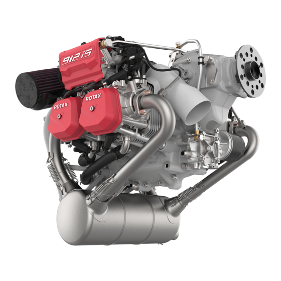
Engine Type 912 i (Series), 915 i (Series)
®
engine types:
®
Engine type
from S/N 10002783
Current valid documentation see:
www.flyrotax.com
SERVICE INSTRUCTION
Serial number
74-20-00
Page 1 of 15
Advertisement


Need help?
Do you have a question about the 912 i Series and is the answer not in the manual?
Questions and answers