Sign In
Upload
Manuals
Brands
STMicroelectronics Manuals
Computer Hardware
STM32F302xC
STMicroelectronics STM32F302xC MCUs Manuals
Manuals and User Guides for STMicroelectronics STM32F302xC MCUs. We have
1
STMicroelectronics STM32F302xC MCUs manual available for free PDF download: Reference Manual
STMicroelectronics STM32F302xC Reference Manual (1080 pages)
advanced ARM-based 32-bit MCUs
Brand:
STMicroelectronics
| Category:
Computer Hardware
| Size: 12.52 MB
Table of Contents
Related Documents
1
Table of Contents
2
Overview of the Manual
40
Table 1. Available Features Related to each Product
40
Documentation Conventions
42
List of Abbreviations for Registers
42
Glossary
42
Peripheral Availability
42
System and Memory Overview
43
System Architecture
43
Figure 1. Stm32F302Xb/C System Architecture
44
Figure 2. Stm32F302X6/8 System Architecture
44
Figure 3. Stm32F302Xd/E System Architecture
45
S0: I-Bus
45
S1: D-Bus
45
S2: S-Bus
45
S3, S4: DMA-Bus
45
Busmatrix
46
Memory Organization
47
Introduction
47
Memory Map and Register Boundary Addresses
47
Table 2. Stm32F302Xb/C Peripheral Register Boundary Addresses
47
Table 3. Stm32F302Xd/E Peripheral Register Boundary Addresses
50
Table 4. Stm32F302X6/X8 Peripheral Register Boundary Addresses
53
Embedded SRAM
55
Parity Check
55
Flash Memory Overview
55
Boot Configuration
56
Embedded Boot Loader
56
Table 5. Boot Modes
56
Embedded Flash Memory
57
Flash Main Features
57
Flash Memory Functional Description
57
Flash Memory Organization
57
Table 6. Flash Module Organization
58
Read Operations
59
Flash Program and Erase Operations
60
Figure 4. Programming Procedure
62
Figure 5. Flash Memory Page Erase Procedure
64
Figure 6. Flash Memory Mass Erase Procedure
65
Memory Protection
67
Read Protection
67
Table 7. Flash Memory Read Protection Status
67
Write Protection
69
Table 8. Access Status Versus Protection Level and Execution Modes
69
Option Byte Block Write Protection
70
Flash Interrupts
70
Table 9. Flash Interrupt Request
70
Flash Register Description
71
Flash Access Control Register (FLASH_ACR)
71
Flash Key Register (FLASH_KEYR)
71
Key Register (FLASH_KEYR)
71
Flash Option Key Register (FLASH_OPTKEYR)
72
Flash Status Register (FLASH_SR)
72
Flash Control Register (FLASH_CR)
73
Flash Address Register (FLASH_AR)
74
Option Byte Register (FLASH_OBR)
75
Write Protection Register (FLASH_WRPR)
76
Flash Register Map
76
Table 10. Flash Interface - Register Map and Reset Values
76
Option Byte Description
78
Table 11. Option Byte Format
78
Table 12. Option Byte Organization
78
Table 13. Description of the Option Bytes
79
Cyclic Redundancy Check Calculation Unit (CRC)
81
Introduction
81
CRC Main Features
81
CRC Functional Description
82
CRC Block Diagram
82
CRC Internal Signals
82
CRC Operation
82
Table 14. CRC Internal Input/Output Signals
82
Figure 7. CRC Calculation Unit Block Diagram
82
CRC Registers
84
Data Register (CRC_DR)
84
Independent Data Register (CRC_IDR)
84
Control Register (CRC_CR)
85
Initial CRC Value (CRC_INIT)
85
CRC Polynomial (CRC_POL)
86
CRC Register Map
86
Table 15. CRC Register Map and Reset Values
86
Peripheral Interconnect Matrix
87
Introduction
87
Connection Summary
87
Table 16. Stm32F302Xx Peripherals Interconnect Matrix
87
Interconnection Details
90
DMA Interconnections
90
From ADC to ADC
90
From ADC to TIM
90
From TIM and EXTI to ADC
91
From OPAMP to ADC
91
From TS to ADC
91
From VBAT to ADC
91
Table 17. Vrefopampx to ADC Channel
91
Table 18. OPAMP Output to ADC Input
91
From VREFINT to ADC
92
From COMP to TIM
92
Table 19. Comparator Outputs to Timer Inputs
92
From TIM to COMP
93
From DAC to COMP
93
Table 20. Timer Output Selection as Comparator Blanking Source
93
From VREFINT to COMP
94
From DAC to OPAMP
94
From TIM to OPAMP
94
From TIM to TIM
94
From Break Input Sources to TIM
95
From HSE, HSI, LSE, LSI, MCO, RTC to TIM
95
Table 21. Timer Synchronization
95
From TIM and EXTI to DAC
96
From TIM to IRTIM
96
Table 22. Timer and EXTI Signals Triggering DAC1 Conversions
96
Power Control (PWR)
97
Power Supplies
97
Figure 8. Power Supply Overview
97
Battery Backup Domain
98
Independent A/D and D/A Converter Supply and Reference Voltage
98
Voltage Regulator
99
Power Supply Supervisor
100
Power on Reset (Por)/Power down Reset (PDR)
100
Figure 9. Power on Reset/Power down Reset Waveform
100
Programmable Voltage Detector (PVD)
101
Figure 10. PVD Thresholds
101
Low-Power Modes
102
Slowing down System Clocks
102
Table 23. Low-Power Mode Summary
102
Peripheral Clock Gating
103
Sleep Mode
103
Stop Mode
104
Table 24. Sleep-Now
104
Table 25. Sleep-On-Exit
104
Standby Mode
106
Table 26. Stop Mode
106
Table 27. Standby Mode
107
Auto-Wakeup from Low-Power Mode
108
Power Control Registers
109
Power Control Register (PWR_CR)
109
Power Control/Status Register (PWR_CSR)
110
PWR Register Map
112
Table 28. PWR Register Map and Reset Values
112
Reset and Clock Control (RCC)
113
Reset
113
Power Reset
113
System Reset
113
RTC Domain Reset
114
Figure 11. Simplified Diagram of the Reset Circuit
114
Clocks
115
Figure 12. Stm32F302Xb/C Clock Tree
116
Figure 13. Stm32F302Xd/E Clock Tree
117
Figure 14. Stm32F302X6/8 Clock Tree
118
Figure 15. HSE/ LSE Clock Sources
119
HSE Clock
119
HSI Clock
120
LSE Clock
121
Pll
121
Clock Security System (CSS)
122
LSI Clock
122
System Clock (SYSCLK) Selection
122
ADC Clock
123
RTC Clock
123
Timers (Timx) Clock
123
Clock-Out Capability
124
I2S Clock
124
Watchdog Clock
124
Figure 16. Frequency Measurement with TIM16 in Capture Mode
125
Internal/External Clock Measurement with TIM16
125
Low-Power Modes
126
RCC Registers
127
Clock Control Register (RCC_CR)
127
Clock Configuration Register (RCC_CFGR)
128
Clock Interrupt Register (RCC_CIR)
132
APB2 Peripheral Reset Register (RCC_APB2RSTR)
134
APB1 Peripheral Reset Register (RCC_APB1RSTR)
136
AHB Peripheral Clock Enable Register (RCC_AHBENR)
138
APB2 Peripheral Clock Enable Register (RCC_APB2ENR)
140
APB1 Peripheral Clock Enable Register (RCC_APB1ENR)
141
RTC Domain Control Register (RCC_BDCR)
144
Control/Status Register (RCC_CSR)
145
AHB Peripheral Reset Register (RCC_AHBRSTR)
147
Clock Configuration Register 2 (RCC_CFGR2)
148
Clock Configuration Register 3 (RCC_CFGR3)
150
RCC Register Map
153
Table 29. RCC Register Map and Reset Values
153
General-Purpose I/Os (GPIO)
155
Introduction
155
GPIO Main Features
155
GPIO Functional Description
155
Figure 17. Basic Structure of an I/O Port Bit
156
Figure 18. Basic Structure of a Five-Volt Tolerant I/O Port Bit
156
General-Purpose I/O (GPIO)
157
Table 30. Port Bit Configuration Table
157
I/O Pin Alternate Function Multiplexer and Mapping
158
GPIO Locking Mechanism
159
I/O Data Bitwise Handling
159
I/O Port Control Registers
159
I/O Port Data Registers
159
External Interrupt/Wakeup Lines
160
I/O Alternate Function Input/Output
160
Input Configuration
160
Figure 19. Input Floating/Pull Up/Pull down Configurations
161
Output Configuration
161
Alternate Function Configuration
162
Figure 20. Output Configuration
162
Figure 21. Alternate Function Configuration
162
Analog Configuration
163
Figure 22. High Impedance-Analog Configuration
163
Using the GPIO Pins in the RTC Supply Domain
163
Using the HSE or LSE Oscillator Pins as Gpios
163
GPIO Registers
164
GPIO Port Mode Register (Gpiox_Moder) (X =A..H
164
GPIO Port Output Type Register (Gpiox_Otyper) (X = A..H
164
GPIO Port Output Speed Register (Gpiox_Ospeedr)
165
(X = a
165
GPIO Port Pull-Up/Pull-Down Register (Gpiox_Pupdr)
165
GPIO Port Input Data Register (Gpiox_Idr) (X = A..H
166
GPIO Port Output Data Register (Gpiox_Odr) (X = A..H
166
GPIO Port Bit Set/Reset Register (Gpiox_Bsrr) (X = A..H
166
GPIO Port Configuration Lock Register (Gpiox_Lckr)
167
(X = a
167
GPIO Alternate Function Low Register (Gpiox_Afrl)
168
(X = a
168
GPIO Alternate Function High Register (Gpiox_Afrh)
168
GPIO Port Bit Reset Register (Gpiox_Brr) (X =A
169
GPIO Register Map
170
Table 31. GPIO Register Map and Reset Values
170
System Configuration Controller (SYSCFG)
172
SYSCFG Registers
172
SYSCFG Configuration Register 1 (SYSCFG_CFGR1)
172
SYSCFG External Interrupt Configuration Register 1
174
(Syscfg_Exticr1)
174
SYSCFG External Interrupt Configuration Register 2
175
(Syscfg_Exticr2)
175
SYSCFG External Interrupt Configuration Register 3
177
(Syscfg_Exticr3)
177
SYSCFG External Interrupt Configuration Register 4
179
(Syscfg_Exticr4)
179
SYSCFG Configuration Register 2 (SYSCFG_CFGR2)
180
SYSCFG Register Map
182
Table 32. SYSCFG Register Map and Reset Values
182
Direct Memory Access Controller (DMA)
183
Introduction
183
DMA Main Features
183
DMA Implementation
183
Table 33. DMA Implementation
183
DMA Functional Description
184
DMA Transactions
184
Figure 23. DMA Block Diagram
184
Arbiter
185
DMA Channels
185
Programmable Data Width, Data Alignment and Endians
187
Table 34. Programmable Data Width & Endian Behavior (When Bits PINC = MINC = 1)
187
Error Management
188
DMA Interrupts
188
DMA Request Mapping
188
Table 35. DMA Interrupt Requests
188
Figure 24. Stm32F302Xb/C/D/E and Stm32F302X6/8 DMA1 Request Mapping
190
Figure 25. Stm32F302X6/8 DMA1 Request Mapping
191
Table 36. Stm32F302Xb/C/D/E Summary of DMA1 Requests for each Channel
192
Table 37. Stm32F302X6/8 Summary of DMA1 Requests for each Channel
192
Figure 26. Stm32F302Xb/C DMA2 Request Mapping
194
Table 38. Stm32F302Xb/C/D/E Summary of DMA2 Requests for each Channel
195
DMA Registers
196
DMA Interrupt Status Register (DMA_ISR)
196
DMA Interrupt Flag Clear Register (DMA
197
DMA Channel X Configuration Register (Dma_Ccrx)
198
(X = 1
198
DMA Channel X Number of Data Register (Dma_Cndtrx) (X = 1
200
DMA Channel X Peripheral Address Register (Dma_Cparx) (X = 1
200
DMA Channel X Memory Address Register (Dma_Cmarx) (X = 1
201
DMA Register Map
202
Table 39. DMA Register Map and Reset Values
202
Interrupts and Events
205
Nested Vectored Interrupt Controller (NVIC)
205
NVIC Main Features
205
Systick Calibration Value Register
205
Interrupt and Exception Vectors
205
Table 40. Stm32F302Xb/C/D/E Vector Table
205
Table 41. Stm32F302X6/8 Vector Table
208
Extended Interrupts and Events Controller (EXTI)
212
Main Features
212
Block Diagram
213
Wakeup Event Management
213
Asynchronous Internal Interrupts
213
Figure 27. External Interrupt/Event Block Diagram
213
Functional Description
214
External and Internal Interrupt/Event Line Mapping
215
Figure 28. External Interrupt/Event GPIO Mapping
215
EXTI Registers
217
Interrupt Mask Register (EXTI_IMR1)
217
Event Mask Register (EXTI_EMR1)
217
Rising Trigger Selection Register (EXTI_RTSR1)
219
Falling Trigger Selection Register (EXTI_FTSR1)
219
Software Interrupt Event Register (EXTI_SWIER1)
220
Pending Register (EXTI_PR1)
220
Interrupt Mask Register (EXTI_IMR2)
221
Event Mask Register (EXTI_EMR2)
221
Rising Trigger Selection Register (EXTI_RTSR2)
222
Falling Trigger Selection Register (EXTI_FTSR2)
222
Software Interrupt Event Register (EXTI_SWIER2)
223
Pending Register (EXTI_PR2)
223
EXTI Register Map
225
Table 42. External Interrupt/Event Controller Register Map and Reset Values
225
Flexible Static Memory Controller (FSMC)
227
FMC Main Features
227
Block Diagram
228
Figure 29. FMC Block Diagram
228
AHB Interface
229
Supported Memories and Transactions
229
External Device Address Mapping
230
NOR/PSRAM Address Mapping
231
Table 43. NOR/PSRAM Bank Selection
231
Table 44. NOR/PSRAM External Memory Address
231
Figure 30. FMC Memory Banks
231
NAND Flash Memory/Pc Card Address Mapping
232
Table 45. NAND/PC Card Memory Mapping and Timing Registers
232
Table 46. NAND Bank Selection
232
NOR Flash/Psram Controller
233
External Memory Interface Signals
234
Table 47. Programmable NOR/PSRAM Access Parameters
234
Table 48. Non-Multiplexed I/O nor Flash Memory
234
Table 49. 16-Bit Multiplexed I/O nor Flash Memory
235
Table 50. Non-Multiplexed I/Os PSRAM/SRAM
235
Table 51. 16-Bit Multiplexed I/O PSRAM
235
Supported Memories and Transactions
236
Table 52. nor Flash/Psram: Example of Supported Memories and Transactions
236
General Timing Rules
237
NOR Flash/Psram Controller Asynchronous Transactions
238
Figure 31. Mode1 Read Access Waveforms
238
Table 53. Fmc_Bcrx Bit Fields
239
Figure 32. Mode1 Write Access Waveforms
239
Table 54. Fmc_Btrx Bit Fields
240
Figure 33. Modea Read Access Waveforms
241
Figure 34. Modea Write Access Waveforms
241
Table 55. Fmc_Bcrx Bit Fields
242
Table 56. Fmc_Btrx Bit Fields
242
Table 57. Fmc_Bwtrx Bit Fields
243
Figure 35. Mode2 and Mode B Read Access Waveforms
243
Figure 36. Mode2 Write Access Waveforms
244
Figure 37. Modeb Write Access Waveforms
244
Table 58. Fmc_Bcrx Bit Fields
245
Table 59. Fmc_Btrx Bit Fields
245
Table 60. Fmc_Bwtrx Bit Fields
246
Figure 38. Modec Read Access Waveforms
246
Table 61. Fmc_Bcrx Bit Fields
247
Figure 39. Modec Write Access Waveforms
247
Table 62. Fmc_Btrx Bit Fields
248
Table 63. Fmc_Bwtrx Bit Fields
248
Figure 40. Moded Read Access Waveforms
249
Figure 41. Moded Write Access Waveforms
249
Table 64. Fmc_Bcrx Bit Fields
250
Table 65. Fmc_Btrx Bit Fields
250
Table 66. Fmc_Bwtrx Bit Fields
251
Figure 42. Muxed Read Access Waveforms
251
Table 67. Fmc_Bcrx Bit Fields
252
Figure 43. Muxed Write Access Waveforms
252
Table 68. Fmc_Btrx Bit Fields
253
Figure 44. Asynchronous Wait During a Read Access Waveforms
254
Synchronous Transactions
255
Figure 45. Asynchronous Wait During a Write Access Waveforms
255
Figure 46. Wait Configuration Waveforms
257
Table 69. Fmc_Bcrx Bit Fields
258
Figure 47. Synchronous Multiplexed Read Mode Waveforms - NOR, PSRAM (CRAM)
258
Table 70. Fmc_Btrx Bit Fields
259
Table 71. Fmc_Bcrx Bit Fields
260
Figure 48. Synchronous Multiplexed Write Mode Waveforms - PSRAM (CRAM)
260
Table 72. Fmc_Btrx Bit Fields
261
NOR/PSRAM Controller Registers
262
NAND Flash/Pc Card Controller
269
External Memory Interface Signals
270
Table 73. Programmable NAND Flash/Pc Card Access Parameters
270
Table 74. 8-Bit NAND Flash
270
Table 75. 16-Bit NAND Flash
271
Table 76. 16-Bit PC Card
271
NAND Flash / PC Card Supported Memories and Transactions
272
Timing Diagrams for NAND Flash Memory and PC Card
272
Table 77. Supported Memories and Transactions
272
NAND Flash Operations
273
Figure 49. NAND Flash/Pc Card Controller Waveforms for Common Memory Access
273
NAND Flash Prewait Functionality
274
Figure 50. Access to Non 'CE Don't Care' NAND-Flash
274
Computation of the Error Correction Code (ECC) in NAND Flash Memory
275
PC Card/Compactflash Operations
276
Table 78. 16-Bit PC-Card Signals and Access Type
277
NAND Flash/Pc Card Controller Registers
278
Table 79. ECC Result Relevant Bits
284
FMC Register Map
285
Table 80. FMC Register Map
285
Analog-To-Digital Converters (ADC)
287
Introduction
287
ADC Main Features
288
Table 81. ADC External Channels Mapping
288
Table 82. ADC Internal Channels Summary
289
ADC Functional Description
290
ADC Block Diagram
290
Figure 51. ADC Block Diagram
290
Pins and Internal Signals
291
Table 83. ADC Internal Signals
291
Table 84. ADC Pins
291
Clocks
292
Figure 52. ADC Clock Scheme
292
ADC1/2 Connectivity
294
Figure 53. ADC1 and ADC2 Connectivity
294
Slave AHB Interface
295
ADC Voltage Regulator (ADVREGEN)
295
Single-Ended and Differential Input Channels
295
Calibration (ADCAL, ADCALDIF, Adcx_Calfact)
296
Figure 54. ADC Calibration
297
Figure 55. Updating the ADC Calibration Factor
298
Figure 56. Mixing Single-Ended and Differential Channels
298
ADC On-Off Control (ADEN, ADDIS, ADRDY)
299
Figure 57. Enabling / Disabling the ADC
299
Constraints When Writing the ADC Control Bits
300
Channel Selection (Sqrx, Jsqrx)
300
Channel-Wise Programmable Sampling Time (SMPR1, SMPR2)
301
Single Conversion Mode (CONT=0)
302
Continuous Conversion Mode (CONT=1)
302
Starting Conversions (ADSTART, JADSTART)
303
Timing
304
Stopping an Ongoing Conversion (ADSTP, JADSTP)
304
Figure 58. Analog to Digital Conversion Time
304
Figure 59. Stopping Ongoing Regular Conversions
305
Conversion on External Trigger and Trigger Polarity
306
Jextsel, Jexten)
306
Table 85. Configuring the Trigger Polarity for Regular External Triggers
306
Figure 60. Stopping Ongoing Regular and Injected Conversions
306
Table 86. Configuring the Trigger Polarity for Injected External Triggers
307
Figure 61. Triggers Are Shared between ADC Master & ADC Slave
307
Table 87. ADC1 (Master) & 2 (Slave) - External Triggers for Regular Channels
308
Table 88. ADC1 & ADC2 - External Trigger for Injected Channels
308
Injected Channel Management
309
Discontinuous Mode (DISCEN, DISCNUM, JDISCEN)
310
Figure 62. Injected Conversion Latency
310
Queue of Context for Injected Conversions
311
Figure 63. Example of JSQR Queue of Context (Sequence Change)
313
Figure 64. Example of JSQR Queue of Context (Trigger Change)
313
Figure 65. Example of JSQR Queue of Context with Overflow before Conversion
314
Figure 66. Example of JSQR Queue of Context with Overflow During Conversion
314
Figure 67. Example of JSQR Queue of Context with Empty Queue (Case JQM=0)
315
Figure 68. Example of JSQR Queue of Context with Empty Queue (Case JQM=1)
315
Figure 69. Flushing JSQR Queue of Context by Setting JADSTP=1 (JQM=0). Case When JADSTP Occurs During an Ongoing Conversion
316
Figure 70. Flushing JSQR Queue of Context by Setting JADSTP=1 (JQM=0)
316
Figure 71. Flushing JSQR Queue of Context by Setting JADSTP=1 (JQM=0). Case When JADSTP Occurs Outside an Ongoing Conversion
317
Figure 72. Flushing JSQR Queue of Context by Setting JADSTP=1 (JQM=1)
317
Figure 73. Flushing JSQR Queue of Context by Setting ADDIS=1 (JQM=0)
318
Figure 74. Flushing JSQR Queue of Context by Setting ADDIS=1 (JQM=1)
318
Programmable Resolution (RES) - Fast Conversion Mode
319
Figure 75. Example of JSQR Queue of Context When Changing SW and HW Triggers
319
End of Conversion, End of Sampling Phase (EOC, JEOC, EOSMP)
320
End of Conversion Sequence (EOS, JEOS)
320
Table 89. TSAR Timings Depending on Resolution
320
Timing Diagrams Example
321
Hardware/Software Triggers)
321
Figure 76. Single Conversions of a Sequence, Software Trigger
321
Figure 77. Continuous Conversion of a Sequence, Software Trigger
321
Data Management
322
Figure 78. Single Conversions of a Sequence, Hardware Trigger
322
Figure 79. Continuous Conversions of a Sequence, Hardware Trigger
322
Table 90. Offset Computation Versus Data Resolution
323
Figure 80. Right Alignment (Offset Disabled, Unsigned Value)
324
Figure 81. Right Alignment (Offset Enabled, Signed Value)
324
Figure 82. Left Alignment (Offset Disabled, Unsigned Value)
325
Figure 83. Left Alignment (Offset Enabled, Signed Value)
325
Figure 84. Example of Overrun (OVR)
326
Dynamic Low-Power Features
328
Figure 85. AUTODLY=1, Regular Conversion in Continuous Mode, Software Trigger
329
Figure 86. AUTODLY=1, Regular HW Conversions Interrupted by Injected Conversions (DISCEN=0; JDISCEN=0)
330
Figure 87. AUTODLY=1, Regular HW Conversions Interrupted by Injected Conversions
330
Figure 88. AUTODLY=1, Regular Continuous Conversions Interrupted by Injected Conversions
332
Figure 89. AUTODLY=1 in Auto- Injected Mode (JAUTO=1)
332
Analog Window Watchdog
333
AWD1CH, AWD2CH, AWD3CH, Awd_Htx, Awd_Ltx, Awdx)
333
Table 91. Analog Watchdog Channel Selection
333
Figure 90. Analog Watchdog's Guarded Area
333
Table 92. Analog Watchdog 1 Comparison
334
Table 93. Analog Watchdog 2 and 3 Comparison
334
Figure 91. Adcy_Awdx_Out Signal Generation (on All Regular Channels)
335
Figure 92. Adcy_Awdx_Out Signal Generation (Awdx Flag Not Cleared by SW)
336
Figure 93. Adcy_Awdx_Out Signal Generation (on a Single Regular Channel)
336
Figure 94. Adcy_Awdx_Out Signal Generation (on All Injected Channels)
336
Dual ADC Modes (Stm32F302Xb/C/D/E Only)
337
Figure 95. Dual ADC Block Diagram (1)
338
Figure 96. Injected Simultaneous Mode on 4 Channels: Dual ADC Mode
339
Figure 97. Regular Simultaneous Mode on 16 Channels: Dual ADC Mode
341
Figure 98. Interleaved Mode on 1 Channel in Continuous Conversion Mode: Dual ADC Mode
343
Figure 99. Interleaved Mode on 1 Channel in Single Conversion Mode: Dual ADC Mode
343
Figure 100. Interleaved Conversion with Injection
344
Figure 101. Alternate Trigger: Injected Group of each ADC
345
Figure 102. Alternate Trigger: 4 Injected Channels (each ADC) in Discontinuous Mode
346
Figure 103. Alternate + Regular Simultaneous
347
Figure 104. Case of Trigger Occurring During Injected Conversion
347
Figure 105. DMA Requests in Regular Simultaneous Mode When Mdma=0B00
348
Figure 106. DMA Requests in Regular Simultaneous Mode When Mdma=0B10
349
Figure 107. DMA Requests in Interleaved Mode When Mdma=0B10
349
Temperature Sensor
350
Figure 108. Temperature Sensor Channel Block Diagram
351
VBAT Supply Monitoring
352
Monitoring the Internal Voltage Reference
353
Figure 109. VBAT Channel Block Diagram
353
Figure 110. VREFINT Channel Block Diagram
353
ADC Interrupts
355
Table 94. ADC Interrupts Per each ADC
355
ADC Registers (for each ADC)
356
ADC Interrupt and Status Register (Adcx_Isr, X=1
356
ADC Interrupt Enable Register (Adcx_Ier, X=1
358
ADC Control Register (Adcx_Cr, X=1
360
ADC Configuration Register (Adcx_Cfgr, X=1
363
ADC Sample Time Register 1 (Adcx_Smpr1, X=1
367
ADC Sample Time Register 2 (Adcx_Smpr2, X=1
369
ADC Watchdog Threshold Register 1 (Adcx_Tr1, X=1
369
ADC Watchdog Threshold Register 2 (Adcx_Tr2, X = 1
370
ADC Watchdog Threshold Register 3 (Adcx_Tr3, X=1
371
ADC Regular Sequence Register 1 (Adcx_Sqr1, X=1
372
ADC Regular Sequence Register 2 (Adcx_Sqr2, X=1
373
ADC Regular Sequence Register 3 (Adcx_Sqr3, X=1
375
ADC Regular Sequence Register 4 (Adcx_Sqr4, X=1
376
ADC Regular Data Register (Adcx_Dr, X=1
377
ADC Injected Sequence Register (Adcx_Jsqr, X=1
378
ADC Offset Register (Adcx_Ofry, X=1
380
ADC Injected Data Register (Adcx_Jdry, X=1
381
ADC Analog Watchdog 2 Configuration Register
381
ADC Analog Watchdog 3 Configuration Register
382
ADC Differential Mode Selection Register (Adcx_Difsel, X=1
382
ADC Calibration Factors (Adcx_Calfact, X=1
383
ADC Common Registers
384
ADC Common Status Register (Adcx_Csr, X=12)
384
ADC Common Control Register (Adcx_Ccr, X=12)
386
Table 95. DELAY Bits Versus ADC Resolution
388
ADC Common Regular Data Register for Dual Mode
389
(Adcx_Cdr, X=12)
389
ADC Register Map
389
Table 96. ADC Global Register Map
389
Table 97. ADC Register Map and Reset Values for each ADC (Offset=0X000 for Master ADC, 0X100 for Slave ADC, X=1
391
Table 98. ADC Register Map and Reset Values (Master and Slave ADC Common Registers) Offset =0X300, X=1 or 34)
392
Digital-To-Analog Converter (DAC1)
393
Introduction
393
DAC1 Main Features
393
DAC Output Buffer Enable
394
Table 99. Dacx Pins
394
Figure 111. DAC1 Block Diagram
394
DAC Channel Enable
395
Single Mode Functional Description
395
DAC Data Format
395
DAC Channel Conversion
395
Figure 112. Data Registers in Single DAC Channel Mode
395
DAC Output Voltage
396
Figure 113. Timing Diagram for Conversion with Trigger Disabled TEN = 0
396
DAC Trigger Selection
397
Table 100. External Triggers (DAC1)
397
Noise Generation
398
Figure 114. DAC LFSR Register Calculation Algorithm
398
Figure 115. DAC Conversion (SW Trigger Enabled) with LFSR Wave Generation
398
Triangle-Wave Generation
399
Figure 116. DAC Triangle Wave Generation
399
Figure 117. DAC Conversion (SW Trigger Enabled) with Triangle Wave Generation
399
DMA Request
400
DAC Registers
401
DAC Control Register (DAC_CR)
401
DAC Software Trigger Register (DAC_SWTRIGR)
403
DAC Channel1 12-Bit Right-Aligned Data Holding Register (DAC_DHR12R1)
403
DAC Channel1 12-Bit Left-Aligned Data Holding Register
404
(Dac_Dhr12L1)
404
DAC Channel1 8-Bit Right-Aligned Data Holding Register (DAC_DHR8R1)
404
DAC Channel1 Data Output Register (DAC_DOR1)
404
DAC Status Register (DAC_SR)
405
DAC Register Map
406
Table 101. DAC Register Map and Reset Values
406
Comparator (COMP)
407
Introduction
407
COMP Main Features
407
COMP Functional Description
408
COMP Block Diagram
408
COMP Pins and Internal Signals
408
Figure 118. Comparator 1 and 2 Block Diagrams
408
Table 102. Stm32F302Xb/C/D/E Comparator Input/Outputs Summary
409
COMP Reset and Clocks
410
Comparator LOCK Mechanism
410
Table 103. Stm32F302X6/8 Comparator Input/Outputs Summary
410
Hysteresis (Stm32F302Xbxc Only)
411
Comparator Output Blanking Function
411
Figure 119. Comparator Output Blanking
411
Power Mode (Stm32F302Xb/C Only)
412
COMP Interrupts
412
COMP Registers
413
COMP1 Control and Status Register (COMP1_CSR)
413
COMP2 Control and Status Register (COMP2_CSR)
415
COMP4 Control and Status Register (COMP4_CSR)
418
COMP6 Control and Status Register (COMP6_CSR)
420
COMP Register Map
422
Table 104. COMP Register Map and Reset Values
422
Operational Amplifier (OPAMP)
423
OPAMP Introduction
423
OPAMP Main Features
423
OPAMP Functional Description
423
General Description
423
Table 105. Connections with Dedicated I/O
423
Clock
424
Operational Amplifiers and Comparators Interconnections
424
Figure 120. Stm32F302Xb/C/D/E Comparator and Operational Amplifier Connections
424
Using the OPAMP Outputs as ADC Inputs
425
Calibration
425
Figure 121. Stm32F302X6/8 Comparator and Operational Amplifier Connections
425
Timer Controlled Multiplexer Mode
426
OPAMP Modes
427
Figure 122. Timer Controlled Multiplexer Mode
427
Figure 123. Standalone Mode: External Gain Setting Mode
428
Figure 124. Follower Configuration
429
Figure 125. PGA Mode, Internal Gain Setting (X2/X4/X8/X16), Inverting Input Not Used
430
Figure 126. PGA Mode, Internal Gain Setting (X2/X4/X8/X16), Inverting Input Used for
430
OPAMP Registers
431
OPAMP1 Control Register (OPAMP1_CSR)
431
OPAMP2 Control Register (OPAMP2_CSR)
433
OPAMP Register Map
436
Table 106. OPAMP Register Map and Reset Values
436
Touch Sensing Controller (TSC)
437
Introduction
437
TSC Main Features
437
TSC Functional Description
438
TSC Block Diagram
438
Surface Charge Transfer Acquisition Overview
438
Figure 127. TSC Block Diagram
438
Figure 128. Surface Charge Transfer Analog I/O Group Structure
439
Reset and Clocks
440
Table 107. Acquisition Sequence Summary
440
Figure 129. Sampling Capacitor Voltage Variation
440
Charge Transfer Acquisition Sequence
441
Figure 130. Charge Transfer Acquisition Sequence
441
Spread Spectrum Feature
442
Max Count Error
442
Table 108. Spread Spectrum Deviation Versus AHB Clock Frequency
442
Figure 131. Spread Spectrum Variation Principle
442
Sampling Capacitor I/O and Channel I/O Mode Selection
443
Table 109. I/O State Depending on Its Mode and IODEF Bit Value
443
Acquisition Mode
444
I/O Hysteresis and Analog Switch Control
444
TSC Low-Power Modes
445
TSC Interrupts
445
Table 110. Effect of Low-Power Modes on TSC
445
Table 111. Interrupt Control Bits
445
TSC Registers
446
TSC Control Register (TSC_CR)
446
TSC Interrupt Enable Register (TSC_IER)
448
TSC Interrupt Clear Register (TSC_ICR)
449
TSC Interrupt Status Register (TSC_ISR)
450
TSC I/O Hysteresis Control Register (TSC_IOHCR)
450
TSC I/O Analog Switch Control Register (TSC_IOASCR)
451
TSC I/O Sampling Control Register (TSC_IOSCR)
451
TSC I/O Channel Control Register (TSC_IOCCR)
452
TSC I/O Group Control Status Register (TSC_IOGCSR)
452
TSC I/O Group X Counter Register (Tsc_Iogxcr) (X = 1
453
TSC Register Map
454
Table 112. TSC Register Map and Reset Values
454
Advanced-Control Timers (TIM1)
456
TIM1 Introduction
456
TIM1 Main Features
456
Figure 132. Advanced-Control Timer Block Diagram
457
TIM1 Functional Description
458
Time-Base Unit
458
Figure 133. Counter Timing Diagram with Prescaler Division Change from 1 to 2
459
Figure 134. Counter Timing Diagram with Prescaler Division Change from 1 to 4
459
Counter Modes
460
Figure 135. Counter Timing Diagram, Internal Clock Divided by 1
461
Figure 136. Counter Timing Diagram, Internal Clock Divided by 2
461
Figure 137. Counter Timing Diagram, Internal Clock Divided by 4
462
Figure 138. Counter Timing Diagram, Internal Clock Divided by N
462
Figure 139. Counter Timing Diagram, Update Event When ARPE=0 (Timx_Arr Not Preloaded)
463
Figure 140. Counter Timing Diagram, Update Event When ARPE=1 (Timx_Arr Preloaded)
463
Figure 141. Counter Timing Diagram, Internal Clock Divided by 1
465
Figure 142. Counter Timing Diagram, Internal Clock Divided by 2
465
Figure 143. Counter Timing Diagram, Internal Clock Divided by 4
466
Figure 144. Counter Timing Diagram, Internal Clock Divided by N
466
Figure 145. Counter Timing Diagram, Update Event When Repetition Counter Is Not Used
467
Figure 146. Counter Timing Diagram, Internal Clock Divided by 1, Timx_Arr = 0X6
468
Figure 147. Counter Timing Diagram, Internal Clock Divided by 2
469
Figure 148. Counter Timing Diagram, Internal Clock Divided by 4, Timx_Arr=0X36
469
Figure 149. Counter Timing Diagram, Internal Clock Divided by N
470
Figure 150. Counter Timing Diagram, Update Event with ARPE=1 (Counter Underflow)
470
Repetition Counter
471
Figure 151. Counter Timing Diagram, Update Event with ARPE=1 (Counter Overflow)
471
Figure 152. Update Rate Examples Depending on Mode and Timx_Rcr Register Settings
472
External Trigger Input
473
Figure 153. External Trigger Input Block
473
Clock Selection
474
Figure 154. Control Circuit in Normal Mode, Internal Clock Divided by 1
474
Figure 155. TI2 External Clock Connection Example
475
Figure 156. Control Circuit in External Clock Mode 1
476
Figure 157. External Trigger Input Block
476
Figure 158. Control Circuit in External Clock Mode 2
477
Capture/Compare Channels
478
Figure 159. Capture/Compare Channel (Example: Channel 1 Input Stage)
478
Figure 160. Capture/Compare Channel 1 Main Circuit
479
Figure 161. Output Stage of Capture/Compare Channel (Channel 1, Idem Ch. 2 and 3)
480
Figure 162. Output Stage of Capture/Compare Channel (Channel 4)
480
Input Capture Mode
481
Figure 163. Output Stage of Capture/Compare Channel (Channel 5, Idem Ch. 6)
481
PWM Input Mode
482
Forced Output Mode
483
Figure 164. PWM Input Mode Timing
483
Output Compare Mode
484
PWM Mode
485
Figure 165. Output Compare Mode, Toggle on OC1
485
Figure 166. Edge-Aligned PWM Waveforms (ARR=8)
486
Figure 167. Center-Aligned PWM Waveforms (ARR=8)
487
Asymmetric PWM Mode
488
Combined PWM Mode
489
Figure 168. Generation of 2 Phase-Shifted PWM Signals with 50% Duty Cycle
489
Combined 3-Phase PWM Mode
490
Figure 169. Combined PWM Mode on Channel 1 and 3
490
Complementary Outputs and Dead-Time Insertion
491
Figure 170. 3-Phase Combined PWM Signals with Multiple Trigger Pulses Per Period
491
Figure 171. Complementary Output with Dead-Time Insertion
492
Figure 172. Dead-Time Waveforms with Delay Greater than the Negative Pulse
492
Using the Break Function
493
Figure 173. Dead-Time Waveforms with Delay Greater than the Positive Pulse
493
Figure 174. Various Output Behavior in Response to a Break Event on BKIN (OSSI = 1)
496
Table 113. Behavior of Timer Outputs Versus BRK/BRK2 Inputs
497
Figure 175. PWM Output State Following BKIN and BKIN2 Pins Assertion (OSSI=1)
497
Clearing the Ocxref Signal on an External Event
498
Figure 176. PWM Output State Following BKIN Assertion (OSSI=0)
498
Figure 177. Clearing Timx Ocxref
499
6-Step PWM Generation
500
Figure 178. 6-Step Generation, COM Example (OSSR=1)
500
One-Pulse Mode
501
Figure 179. Example of One Pulse Mode
501
Retriggerable One Pulse Mode (OPM)
502
Encoder Interface Mode
503
Figure 180. Retriggerable One Pulse Mode
503
Table 114. Counting Direction Versus Encoder Signals
504
Figure 181. Example of Counter Operation in Encoder Interface Mode
504
UIF Bit Remapping
505
Figure 182. Example of Encoder Interface Mode with TI1FP1 Polarity Inverted
505
Timer Input XOR Function
506
Interfacing with Hall Sensors
506
Figure 183. Measuring Time Interval between Edges on 3 Signals
506
Figure 184. Example of Hall Sensor Interface
508
Timer Synchronization
509
Figure 185. Control Circuit in Reset Mode
509
Figure 186. Control Circuit in Gated Mode
510
Figure 187. Control Circuit in Trigger Mode
511
Figure 188. Control Circuit in External Clock Mode 2 + Trigger Mode
512
ADC Synchronization
513
DMA Burst Mode
513
Debug Mode
514
TIM1 Registers
515
TIM1 Control Register 1 (Timx_Cr1)
515
TIM1 Control Register 2 (Timx_Cr2)
516
TIM1 Slave Mode Control Register (Timx_Smcr)
519
TIM1 Dma/Interrupt Enable Register (Timx_Dier)
521
Table 115. TIM1 Internal Trigger Connection
521
TIM1 Status Register (Timx_Sr)
523
TIM1 Event Generation Register (Timx_Egr)
525
TIM1 Capture/Compare Mode Register 1 (Timx_Ccmr1)
526
TIM1 Capture/Compare Mode Register 2 (Timx_Ccmr2)
530
TIM1 Capture/Compare Enable Register (Timx_Ccer)
532
Table 116. Output Control Bits for Complementary Ocx and Ocxn Channels with Break Feature
535
TIM1 Counter (Timx_Cnt)
536
TIM1 Prescaler (Timx_Psc)
536
TIM1 Auto-Reload Register (Timx_Arr)
536
TIM1 Repetition Counter Register (Timx_Rcr)
537
TIM1 Capture/Compare Register 1 (Timx_Ccr1)
537
TIM1 Capture/Compare Register 2 (Timx_Ccr2)
538
TIM1 Capture/Compare Register 3 (Timx_Ccr3)
538
TIM1 Capture/Compare Register 4 (Timx_Ccr4)
539
TIM1 Break and Dead-Time Register (Timx_Bdtr)
539
TIM1 DMA Control Register (Timx_Dcr)
542
TIM1 DMA Address for Full Transfer (Timx_Dmar)
543
TIM1 Option Registers (Timx_Or)
544
TIM1 Capture/Compare Mode Register 3 (Timx_Ccmr3)
544
TIM1 Capture/Compare Register 5 (Timx_Ccr5)
545
TIM1 Capture/Compare Register 6 (Timx_Ccr6)
546
TIM1 Register Map
547
Table 117. TIM1 Register Map and Reset Values
547
General-Purpose Timers (TIM2/TIM3/TIM4)
550
TIM2/TIM3/TIM4 Introduction
550
TIM2/TIM3/TIM4 Main Features
550
Figure 189. General-Purpose Timer Block Diagram
551
TIM2/TIM3/TIM4 Functional Description
552
Time-Base Unit
552
Figure 190. Counter Timing Diagram with Prescaler Division Change from 1 to 2
553
Figure 191. Counter Timing Diagram with Prescaler Division Change from 1 to 4
553
Counter Modes
554
Figure 192. Counter Timing Diagram, Internal Clock Divided by 1
554
Figure 193. Counter Timing Diagram, Internal Clock Divided by 2
555
Figure 194. Counter Timing Diagram, Internal Clock Divided by 4
555
Figure 195. Counter Timing Diagram, Internal Clock Divided by N
556
Figure 196. Counter Timing Diagram, Update Event When ARPE=0 (Timx_Arr Not Preloaded)
556
Figure 197. Counter Timing Diagram, Update Event When ARPE=1 (Timx_Arr Preloaded)
557
Figure 198. Counter Timing Diagram, Internal Clock Divided by 1
558
Figure 199. Counter Timing Diagram, Internal Clock Divided by 2
558
Figure 200. Counter Timing Diagram, Internal Clock Divided by 4
559
Figure 201. Counter Timing Diagram, Internal Clock Divided by N
559
Figure 202. Counter Timing Diagram, Update Event When Repetition Counter
560
Figure 203. Counter Timing Diagram, Internal Clock Divided by 1, Timx_Arr=0X6
561
Figure 204. Counter Timing Diagram, Internal Clock Divided by 2
562
Figure 205. Counter Timing Diagram, Internal Clock Divided by 4, Timx_Arr=0X36
562
Figure 206. Counter Timing Diagram, Internal Clock Divided by N
563
Figure 207. Counter Timing Diagram, Update Event with ARPE=1 (Counter Underflow)
563
Clock Selection
564
Figure 208. Counter Timing Diagram, Update Event with ARPE=1 (Counter Overflow)
564
Figure 209. Control Circuit in Normal Mode, Internal Clock Divided by 1
565
Figure 210. TI2 External Clock Connection Example
565
Figure 211. Control Circuit in External Clock Mode 1
566
Figure 212. External Trigger Input Block
567
Capture/Compare Channels
568
Figure 213. Control Circuit in External Clock Mode 2
568
Figure 214. Capture/Compare Channel (Example: Channel 1 Input Stage)
569
Figure 215. Capture/Compare Channel 1 Main Circuit
569
Input Capture Mode
570
Figure 216. Output Stage of Capture/Compare Channel (Channel 1)
570
PWM Input Mode
571
Forced Output Mode
572
Figure 217. PWM Input Mode Timing
572
Output Compare Mode
573
PWM Mode
574
Figure 218. Output Compare Mode, Toggle on OC1
574
Figure 219. Edge-Aligned PWM Waveforms (ARR=8)
575
Figure 220. Center-Aligned PWM Waveforms (ARR=8)
576
Asymmetric PWM Mode
577
Figure 221. Generation of 2 Phase-Shifted PWM Signals with 50% Duty Cycle
577
Combined PWM Mode
578
Clearing the Ocxref Signal on an External Event
579
Figure 222. Combined PWM Mode on Channels 1 and 3
579
Figure 223. Clearing Timx Ocxref
580
One-Pulse Mode
581
Figure 224. Example of One-Pulse Mode
581
Retriggerable One Pulse Mode (OPM)
582
Encoder Interface Mode
583
Figure 225. Retriggerable One Pulse Mode
583
Table 118. Counting Direction Versus Encoder Signals
584
Figure 226. Example of Counter Operation in Encoder Interface Mode
584
UIF Bit Remapping
585
Timer Input XOR Function
585
Figure 227. Example of Encoder Interface Mode with TI1FP1 Polarity Inverted
585
Timers and External Trigger Synchronization
586
Figure 228. Control Circuit in Reset Mode
586
Figure 229. Control Circuit in Gated Mode
587
Figure 230. Control Circuit in Trigger Mode
588
Timer Synchronization
589
Figure 231. Control Circuit in External Clock Mode 2 + Trigger Mode
589
Figure 232. Master/Slave Timer Example
590
Figure 233. Gating TIM2 with OC1REF of TIM3
591
Figure 234. Gating TIM2 with Enable of TIM3
592
Figure 235. Triggering TIM2 with Update of TIM3
592
Figure 236. Triggering TIM2 with Enable of TIM3
593
DMA Burst Mode
594
Figure 237. Triggering TIM3 and TIM2 with TIM3 TI1 Input
594
Debug Mode
595
TIM2/TIM3/TIM4 Registers
596
Timx Control Register 1 (Timx_Cr1)
596
Timx Control Register 2 (Timx_Cr2)
597
Timx Slave Mode Control Register (Timx_Smcr)
599
Table 119. Timx Internal Trigger Connection
601
Timx Dma/Interrupt Enable Register (Timx_Dier)
602
Timx Status Register (Timx_Sr)
603
Timx Event Generation Register (Timx_Egr)
604
Timx Capture/Compare Mode Register 1 (Timx_Ccmr1)
605
Timx Capture/Compare Mode Register 2 (Timx_Ccmr2)
609
Timx Capture/Compare Enable Register (Timx_Ccer)
611
Timx Counter (Timx_Cnt)
612
Table 120. Output Control Bit for Standard Ocx Channels
612
Timx Prescaler (Timx_Psc)
613
Timx Auto-Reload Register (Timx_Arr)
613
Timx Capture/Compare Register 1 (Timx_Ccr1)
614
Timx Capture/Compare Register 2 (Timx_Ccr2)
614
Timx Capture/Compare Register 3 (Timx_Ccr3)
615
Timx Capture/Compare Register 4 (Timx_Ccr4)
615
Timx DMA Control Register (Timx_Dcr)
616
Timx DMA Address for Full Transfer (Timx_Dmar)
616
Timx Register Map
617
Table 121. TIM2/TIM3/TIM4 Register Map and Reset Values
617
General-Purpose Timers (TIM15/TIM16/TIM17)
619
TIM15/TIM16/TIM17 Introduction
619
TIM15 Main Features
619
TIM16/TIM17 Main Features
620
Figure 238. TIM15 Block Diagram
621
Figure 239. TIM16/TIM17 Block Diagram
622
TIM15/TIM16/TIM17 Functional Description
623
Time-Base Unit
623
Figure 240. Counter Timing Diagram with Prescaler Division Change from 1 to 2
624
Figure 241. Counter Timing Diagram with Prescaler Division Change from 1 to 4
624
Counter Modes
625
Figure 242. Counter Timing Diagram, Internal Clock Divided by 1
626
Figure 243. Counter Timing Diagram, Internal Clock Divided by 2
626
Figure 244. Counter Timing Diagram, Internal Clock Divided by 4
627
Figure 245. Counter Timing Diagram, Internal Clock Divided by N
627
Repetition Counter
629
Clock Selection
630
Figure 248. Update Rate Examples Depending on Mode and Timx_Rcr Register Settings
630
Figure 249. Control Circuit in Normal Mode, Internal Clock Divided by 1
631
Figure 250. TI2 External Clock Connection Example
631
Capture/Compare Channels
632
Figure 251. Control Circuit in External Clock Mode 1
632
Figure 252. Capture/Compare Channel (Example: Channel 1 Input Stage)
633
Figure 253. Capture/Compare Channel 1 Main Circuit
633
Figure 254. Output Stage of Capture/Compare Channel (Channel 1)
634
Figure 255. Output Stage of Capture/Compare Channel (Channel 2 for TIM15)
634
Input Capture Mode
635
PWM Input Mode (Only for TIM15)
636
Figure 256. PWM Input Mode Timing
636
Forced Output Mode
637
Output Compare Mode
637
PWM Mode
638
Figure 257. Output Compare Mode, Toggle on OC1
638
Combined PWM Mode (TIM15 Only)
639
Figure 258. Edge-Aligned PWM Waveforms (ARR=8)
639
Figure 259. Combined PWM Mode on Channel 1 and 2
640
Complementary Outputs and Dead-Time Insertion
641
Table 123. Output Control Bits for Complementary Ocx and Ocxn Channels with Break Feature
641
Figure 260. Complementary Output with Dead-Time Insertion
641
Figure 261. Dead-Time Waveforms with Delay Greater than the Negative Pulse
642
Figure 262. Dead-Time Waveforms with Delay Greater than the Positive Pulse
642
Using the Break Function
643
Figure 263. Output Behavior in Response to a Break
645
One-Pulse Mode
646
Figure 264. Example of One Pulse Mode
646
UIF Bit Remapping
647
Timer Input XOR Function (TIM15 Only)
648
Figure 265. Measuring Time Interval between Edges on 2 Signals
648
External Trigger Synchronization (TIM15 Only)
649
Figure 266. Control Circuit in Reset Mode
649
Figure 267. Control Circuit in Gated Mode
650
Slave Mode: Combined Reset + Trigger Mode (TIM15 Only)
651
DMA Burst Mode
651
Figure 268. Control Circuit in Trigger Mode
651
Timer Synchronization (TIM15)
653
Debug Mode
653
TIM15 Registers
654
TIM15 Control Register 1 (TIM15_CR1)
654
TIM15 Control Register 2 (TIM15_CR2)
655
TIM15 Slave Mode Control Register (TIM15_SMCR)
657
Table 122. Timx Internal Trigger Connection
657
TIM15 Dma/Interrupt Enable Register (TIM15_DIER)
658
TIM15 Status Register (TIM15_SR)
659
TIM15 Event Generation Register (TIM15_EGR)
661
TIM15 Capture/Compare Mode Register 1 (TIM15_CCMR1)
662
TIM15 Capture/Compare Enable Register (TIM15_CCER)
665
TIM15 Counter (TIM15_CNT)
668
TIM15 Prescaler (TIM15_PSC)
668
TIM15 Auto-Reload Register (TIM15_ARR)
668
TIM15 Repetition Counter Register (TIM15_RCR)
669
TIM15 Capture/Compare Register 1 (TIM15_CCR1)
669
TIM15 Capture/Compare Register 2 (TIM15_CCR2)
670
TIM15 Break and Dead-Time Register (TIM15_BDTR)
670
TIM15 DMA Control Register (TIM15_DCR)
672
TIM15 DMA Address for Full Transfer (TIM15_DMAR)
672
TIM15 Register Map
673
Table 124. TIM15 Register Map and Reset Values
673
TIM16/TIM17 Registers
675
TIM16/TIM17 Control Register 1 (Timx_Cr1)
675
TIM16/TIM17 Control Register 2 (Timx_Cr2)
676
TIM16/TIM17 Dma/Interrupt Enable Register (Timx_Dier)
677
TIM16/TIM17 Status Register (Timx_Sr)
678
TIM16/TIM17 Event Generation Register (Timx_Egr)
679
TIM16/TIM17 Capture/Compare Mode Register 1 (Timx_Ccmr1)
680
TIM16/TIM17 Capture/Compare Enable Register (Timx_Ccer)
682
TIM16/TIM17 Counter (Timx_Cnt)
684
Table 125. Output Control Bits for Complementary Ocx and Ocxn Channels with Break Feature
684
TIM16/TIM17 Prescaler (Timx_Psc)
685
TIM16/TIM17 Auto-Reload Register (Timx_Arr)
685
TIM16/TIM17 Repetition Counter Register (Timx_Rcr)
686
TIM16/TIM17 Capture/Compare Register 1 (Timx_Ccr1)
686
TIM16/TIM17 Break and Dead-Time Register (Timx_Bdtr)
687
TIM16/TIM17 DMA Control Register (Timx_Dcr)
689
TIM16/TIM17 DMA Address for Full Transfer (Timx_Dmar)
689
TIM16 Option Register (TIM16_OR)
690
TIM16/TIM17 Register Map
691
Table 126. TIM16/TIM17 Register Map and Reset Values
691
Basic Timers (TIM6)
693
TIM6 Introduction
693
TIM6 Main Features
693
Figure 269. Basic Timer Block Diagram
693
TIM6 Functional Description
694
Time-Base Unit
694
Figure 270. Counter Timing Diagram with Prescaler Division Change from 1 to 2
695
Figure 271. Counter Timing Diagram with Prescaler Division Change from 1 to 4
695
Counting Mode
696
Figure 272. Counter Timing Diagram, Internal Clock Divided by 1
696
Figure 273. Counter Timing Diagram, Internal Clock Divided by 2
697
Figure 274. Counter Timing Diagram, Internal Clock Divided by 4
697
Figure 275. Counter Timing Diagram, Internal Clock Divided by N
698
UIF Bit Remapping
699
Clock Source
699
Debug Mode
700
TIM6 Registers
700
TIM6 Control Register 1 (Timx_Cr1)
700
Figure 278. Control Circuit in Normal Mode, Internal Clock Divided by 1
700
TIM6 Control Register 2 (Timx_Cr2)
702
TIM6 Dma/Interrupt Enable Register (Timx_Dier)
702
TIM6 Status Register (Timx_Sr)
703
TIM6 Event Generation Register (Timx_Egr)
703
TIM6 Counter (Timx_Cnt)
703
TIM6 Prescaler (Timx_Psc)
704
TIM6 Auto-Reload Register (Timx_Arr)
704
TIM6 Register Map
705
Table 127. TIM6 Register Map and Reset Values
705
Infrared Interface (IRTIM)
706
Figure 279. IR Internal Hardware Connections with TIM16 and TIM17
706
System Window Watchdog (WWDG)
707
Introduction
707
WWDG Main Features
707
WWDG Functional Description
707
Enabling the Watchdog
708
Controlling the Downcounter
708
Advanced Watchdog Interrupt Feature
708
Figure 280. Watchdog Block Diagram
708
How to Program the Watchdog Timeout
709
Figure 281. Window Watchdog Timing Diagram
709
Debug Mode
710
WWDG Registers
710
Control Register (WWDG_CR)
710
Configuration Register (WWDG_CFR)
711
Status Register (WWDG_SR)
711
WWDG Register Map
712
Table 128. WWDG Register Map and Reset Values
712
Independent Watchdog (IWDG)
713
Introduction
713
IWDG Main Features
713
IWDG Functional Description
713
IWDG Block Diagram
713
Figure 282. Independent Watchdog Block Diagram
713
Window Option
714
Hardware Watchdog
715
Behavior in Stop and Standby Modes
715
Register Access Protection
715
Debug Mode
715
IWDG Registers
716
Key Register (IWDG_KR)
716
Prescaler Register (IWDG_PR)
717
Reload Register (IWDG_RLR)
718
Status Register (IWDG_SR)
719
Window Register (IWDG_WINR)
720
IWDG Register Map
721
Table 129. IWDG Register Map and Reset Values
721
Real-Time Clock (RTC)
722
Introduction
722
RTC Main Features
723
RTC Functional Description
724
RTC Block Diagram
724
Figure 283. RTC Block Diagram
724
Gpios Controlled by the RTC
725
Table 130. RTC Pin PC13 Configuration
726
Table 131. LSE Pin PC14 Configuration
726
Table 132. LSE Pin PC15 Configuration
726
Clock and Prescalers
727
Real-Time Clock and Calendar
727
Programmable Alarms
728
Periodic Auto-Wakeup
728
RTC Initialization and Configuration
729
Reading the Calendar
730
Resetting the RTC
731
RTC Synchronization
732
RTC Reference Clock Detection
732
RTC Smooth Digital Calibration
733
Time-Stamp Function
735
Tamper Detection
736
Calibration Clock Output
737
Alarm Output
738
RTC Low-Power Modes
738
RTC Interrupts
738
Table 133. Effect of Low-Power Modes on RTC
738
RTC Registers
739
RTC Time Register (RTC_TR)
739
Table 134. Interrupt Control Bits
739
RTC Date Register (RTC_DR)
740
RTC Control Register (RTC_CR)
742
RTC Initialization and Status Register (RTC_ISR)
745
RTC Prescaler Register (RTC_PRER)
748
RTC Wakeup Timer Register (RTC_WUTR)
749
RTC Alarm a Register (RTC_ALRMAR)
750
RTC Alarm B Register (RTC_ALRMBR)
751
RTC Write Protection Register (RTC_WPR)
752
RTC Sub Second Register (RTC_SSR)
752
RTC Shift Control Register (RTC_SHIFTR)
753
RTC Timestamp Time Register (RTC_TSTR)
754
RTC Timestamp Date Register (RTC_TSDR)
755
RTC Time-Stamp Sub Second Register (RTC_TSSSR)
756
RTC Calibration Register (RTC_CALR)
757
RTC Tamper and Alternate Function Configuration Register
758
(Rtc_Tafcr)
758
RTC Alarm a Sub Second Register (RTC_ALRMASSR)
761
RTC Alarm B Sub Second Register (RTC_ALRMBSSR)
762
RTC Backup Registers (Rtc_Bkpxr)
763
RTC Register Map
763
Table 135. RTC Register Map and Reset Values
763
Inter-Integrated Circuit (I2C) Interface
765
Introduction
765
I2C Main Features
765
I2C Implementation
766
I2C Functional Description
766
Table 136. Stm32F302Xx I2C Implementation
766
Figure 284. I2C Block Diagram
767
I2C Block Diagram
767
I2C Clock Requirements
768
Mode Selection
768
Figure 285. I2C Bus Protocol
769
I2C Initialization
770
Table 137. Comparison of Analog Vs. Digital Filters
770
Figure 286. Setup and Hold Timings
771
Table 138. I2C-SMBUS Specification Data Setup and Hold Times
772
Figure 287. I2C Initialization Flowchart
774
Software Reset
774
Data Transfer
775
Figure 288. Data Reception
775
Figure 289. Data Transmission
776
I2C Slave Mode
777
Table 139. I2C Configuration Table
777
Figure 290. Slave Initialization Flowchart
780
Figure 291. Transfer Sequence Flowchart for I2C Slave Transmitter, NOSTRETCH=0
781
Figure 292. Transfer Sequence Flowchart for I2C Slave Transmitter, NOSTRETCH=1
782
Figure 293. Transfer Bus Diagrams for I2C Slave Transmitter
783
Figure 294. Transfer Sequence Flowchart for Slave Receiver with NOSTRETCH=0
784
Figure 295. Transfer Sequence Flowchart for Slave Receiver with NOSTRETCH=1
785
Figure 296. Transfer Bus Diagrams for I2C Slave Receiver
785
I2C Master Mode
786
Figure 297. Master Clock Generation
787
Table 140. I2C-SMBUS Specification Clock Timings
788
Figure 298. Master Initialization Flowchart
789
Figure 299. 10-Bit Address Read Access with HEAD10R=0
789
Figure 300. 10-Bit Address Read Access with HEAD10R=1
790
Figure 301. Transfer Sequence Flowchart for I2C Master Transmitter for N≤255 Bytes
791
Figure 302. Transfer Sequence Flowchart for I2C Master Transmitter for N>255 Bytes
792
Figure 303. Transfer Bus Diagrams for I2C Master Transmitter
793
Figure 304. Transfer Sequence Flowchart for I2C Master Receiver for N≤255 Bytes
795
Figure 305. Transfer Sequence Flowchart for I2C Master Receiver for N >255 Bytes
796
Figure 306. Transfer Bus Diagrams for I2C Master Receiver
797
I2C_TIMINGR Register Configuration Examples
798
Table 141. Examples of Timings Settings for Fi2Cclk = 8 Mhz
798
Table 142. Examples of Timings Settings for Fi2Cclk = 16 Mhz
798
Smbus Specific Features
799
Table 143. Examples of Timings Settings for Fi2Cclk = 48 Mhz
799
Table 144. Smbus Timeout Specifications
801
Figure 307. Timeout Intervals for T
802
Smbus Initialization
802
Table 145. SMBUS with PEC Configuration
803
Smbus: I2C_TIMEOUTR Register Configuration Examples
804
Table 146. Examples of TIMEOUTA Settings for Various I2CCLK Frequencies
804
Table 148. Examples of TIMEOUTA Settings for Various I2CCLK Frequencies
804
Smbus Slave Mode
805
Figure 308. Transfer Sequence Flowchart for Smbus Slave Transmitter N Bytes + PEC
806
Figure 309. Transfer Bus Diagrams for Smbus Slave Transmitter (SBC=1)
806
Figure 310. Transfer Sequence Flowchart for Smbus Slave Receiver N Bytes + PEC
808
Figure 311. Bus Transfer Diagrams for Smbus Slave Receiver (SBC=1)
809
Figure 312. Bus Transfer Diagrams for Smbus Master Transmitter
810
Figure 313. Bus Transfer Diagrams for Smbus Master Receiver
812
Error Conditions
813
Wakeup from Stop Mode on Address Match
813
DMA Requests
815
Debug Mode
816
I2C Low-Power Modes
816
I2C Interrupts
816
Table 149. Low-Power Modes
816
Table 150. I2C Interrupt Requests
816
Figure 314. I2C Interrupt Mapping Diagram
817
I2C Registers
818
Control Register 1 (I2C_CR1)
818
Control Register 2 (I2C_CR2)
821
Own Address 1 Register (I2C_OAR1)
824
Own Address 2 Register (I2C_OAR2)
825
Timing Register (I2C_TIMINGR)
826
Timeout Register (I2C_TIMEOUTR)
827
Interrupt and Status Register (I2C_ISR)
828
Interrupt Clear Register (I2C_ICR)
830
PEC Register (I2C_PECR)
831
Receive Data Register (I2C_RXDR)
832
Transmit Data Register (I2C_TXDR)
832
I2C Register Map
833
Table 151. I2C Register Map and Reset Values
833
Universal Synchronous Asynchronous Receiver
835
Transmitter (USART)
835
Introduction
835
USART Main Features
835
USART Extended Features
836
USART Implementation
837
Table 152. Stm32F302Xx USART Features
837
USART Functional Description
838
Figure 315. USART Block Diagram
839
USART Character Description
840
Figure 316. Word Length Programming
841
USART Transmitter
842
Figure 317. Configurable Stop Bits
843
Figure 318. TC/TXE Behavior When Transmitting
844
USART Receiver
844
Figure 319. Start Bit Detection When Oversampling by 16 or 8
845
Character Reception
846
Figure 320. Data Sampling When Oversampling by 16
849
Figure 321. Data Sampling When Oversampling by 8
849
Table 153. Noise Detection from Sampled Data
849
USART Baud Rate Generation
851
Oversampling by 16 or by 8
852
Table 154. Error Calculation for Programmed Baud Rates at F
852
Table 155. Tolerance of the USART Receiver When BRR [3:0] = 0000
853
Tolerance of the USART Receiver to Clock Deviation
853
Table 156. Tolerance of the USART Receiver When BRR [3:0] Is Different from 0000
854
USART Auto Baud Rate Detection
854
Multiprocessor Communication Using USART
855
Figure 322. Mute Mode Using Idle Line Detection
856
Figure 323. Mute Mode Using Address Mark Detection
857
Modbus Communication Using USART
857
Table 157. Frame Formats
858
USART Parity Control
858
USART LIN (Local Interconnection Network) Mode
859
Figure 324. Break Detection in LIN Mode (11-Bit Break Length - LBDL Bit Is Set)
860
Figure 325. Break Detection in LIN Mode Vs. Framing Error Detection
861
USART Synchronous Mode
861
Figure 326. USART Example of Synchronous Transmission
862
Figure 327. USART Data Clock Timing Diagram (M Bits = 00)
862
Figure 328. USART Data Clock Timing Diagram (M Bits = 01)
863
Figure 329. RX Data Setup/Hold Time
863
USART Single-Wire Half-Duplex Communication
864
USART Smartcard Mode
864
Figure 330. ISO 7816-3 Asynchronous Protocol
865
Figure 331. Parity Error Detection Using the 1.5 Stop Bits
866
USART Irda SIR ENDEC Block
869
Figure 332. Irda SIR ENDEC- Block Diagram
870
Figure 333. Irda Data Modulation (3/16) -Normal Mode
871
USART Continuous Communication in DMA Mode
871
Figure 334. Transmission Using DMA
872
RS232 Hardware Flow Control and RS485 Driver Enable
873
Using USART
873
Figure 335. Reception Using DMA
873
Figure 336. Hardware Flow Control between 2 Usarts
873
Figure 337. RS232 RTS Flow Control
874
Figure 338. RS232 CTS Flow Control
875
Wakeup from Stop Mode Using USART
875
USART Low-Power Modes
877
USART Interrupts
877
Table 158. Effect of Low-Power Modes on the USART
877
Table 159. USART Interrupt Requests
877
Figure 339. USART Interrupt Mapping Diagram
878
USART Registers
879
Control Register 1 (USART_CR1)
879
Control Register 2 (USART_CR2)
882
Control Register 3 (USART_CR3)
886
Baud Rate Register (USART_BRR)
890
Guard Time and Prescaler Register (USART_GTPR)
890
Receiver Timeout Register (USART_RTOR)
891
Request Register (USART_RQR)
892
Interrupt and Status Register (USART_ISR)
893
Interrupt Flag Clear Register (USART_ICR)
898
Receive Data Register (USART_RDR)
899
Transmit Data Register (USART_TDR)
899
USART Register Map
900
Table 160. USART Register Map and Reset Values
900
Serial Peripheral Interface / Inter-IC Sound (SPI/I2S)
902
Introduction
902
SPI Main Features
902
I2S Main Features
903
SPI/I2S Implementation
903
Table 161. Stm32F302X6/8 SPI Implementation
903
SPI Functional Description
904
General Description
904
Table 162. Stm32F302Xb/C/D/E SPI Implementation
904
Figure 340. SPI Block Diagram
904
Communications between One Master and One Slave
905
Figure 341. Full-Duplex Single Master/ Single Slave Application
905
Figure 342. Half-Duplex Single Master/ Single Slave Application
906
Standard Multi-Slave Communication
907
Figure 343. Simplex Single Master/Single Slave Application
907
Multi-Master Communication
908
Figure 344. Master and Three Independent Slaves
908
Slave Select (NSS) Pin Management
909
Figure 345. Multi-Master Application
909
Communication Formats
910
Figure 346. Hardware/Software Slave Select Management
910
Figure 347. Data Clock Timing Diagram
911
Configuration of SPI
912
Figure 348. Data Alignment When Data Length Is Not Equal to 8-Bit or 16-Bit
912
Procedure for Enabling SPI
913
Data Transmission and Reception Procedures
913
Figure 349. Packing Data in FIFO for Transmission and Reception
916
Figure 350. Master Full-Duplex Communication
919
Figure 351. Slave Full-Duplex Communication
920
Figure 352. Master Full-Duplex Communication with CRC
921
Figure 353. Master Full-Duplex Communication in Packed Mode
922
SPI Status Flags
923
SPI Error Flags
924
NSS Pulse Mode
925
TI Mode
925
Figure 354. NSSP Pulse Generation in Motorola SPI Master Mode
925
CRC Calculation
926
Figure 355. TI Mode Transfer
926
SPI Interrupts
928
Table 163. SPI Interrupt Requests
928
S Functional Description
929
S General Description
929
Figure 356. I
929
I2S Full Duplex
930
Figure 357. I2S Full-Duplex Block Diagram
930
Supported Audio Protocols
931
Figure 358. I 2 S Philips Protocol Waveforms (16/32-Bit Full Accuracy)
932
Figure 359. I 2 S Philips Standard Waveforms (24-Bit Frame)
932
Figure 360. Transmitting 0X8Eaa33
932
Figure 361. Receiving 0X8Eaa33
933
Figure 362. I
933
Figure 363. Example of 16-Bit Data Frame Extended to 32-Bit Channel Frame
933
Figure 364. MSB Justified 16-Bit or 32-Bit Full-Accuracy Length
934
Figure 365. MSB Justified 24-Bit Frame Length
934
Figure 366. MSB Justified 16-Bit Extended to 32-Bit Packet Frame
934
Figure 367. LSB Justified 16-Bit or 32-Bit Full-Accuracy
935
Figure 368. LSB Justified 24-Bit Frame Length
935
Figure 369. Operations Required to Transmit 0X3478Ae
935
Figure 370. Operations Required to Receive 0X3478Ae
936
Figure 371. LSB Justified 16-Bit Extended to 32-Bit Packet Frame
936
Figure 372. Example of 16-Bit Data Frame Extended to 32-Bit Channel Frame
936
Start-Up Description
937
Figure 373. PCM Standard Waveforms (16-Bit)
937
Figure 374. PCM Standard Waveforms (16-Bit Extended to 32-Bit Packet Frame)
937
Figure 375. Start Sequence in Master Mode
938
Clock Generator
939
Figure 376. Audio Sampling Frequency Definition
939
Figure 377. I
939
I 2 S Master Mode
940
Table 164. Audio-Frequency Precision Using Standard 8 Mhz HSE
940
I 2 S Slave Mode
942
I 2 S Status Flags
944
I 2 S Error Flags
945
DMA Features
946
I 2 S Interrupts
946
Table 165. I
946
SPI and I
947
SPI Control Register 1 (Spix_Cr1)
947
SPI Control Register 2 (Spix_Cr2)
949
SPI Status Register (Spix_Sr)
952
SPI Data Register (Spix_Dr)
953
SPI CRC Polynomial Register (Spix_Crcpr)
953
SPI Rx CRC Register (Spix_Rxcrcr)
955
SPI Tx CRC Register (Spix_Txcrcr)
955
Spix_I 2 S Configuration Register (Spix_I2Scfgr)
956
Spix_I 2 S Prescaler Register (Spix_I2Spr)
958
SPI/I2S Register Map
959
Table 166. SPI Register Map and Reset Values
959
Controller Area Network (Bxcan)
960
Introduction
960
Bxcan Main Features
960
Bxcan General Description
961
CAN 2.0B Active Core
961
Control, Status and Configuration Registers
961
Tx Mailboxes
961
Figure 378. CAN Network Topology
961
Acceptance Filters
962
Bxcan Operating Modes
962
Initialization Mode
962
Normal Mode
962
Sleep Mode (Low-Power)
963
Test Mode
964
Silent Mode
964
Figure 379. Bxcan Operating Modes
964
Loop Back Mode
965
Loop Back Combined with Silent Mode
965
Figure 380. Bxcan in Silent Mode
965
Figure 381. Bxcan in Loop Back Mode
965
Behavior in Debug Mode
966
Bxcan Functional Description
966
Transmission Handling
966
Figure 382. Bxcan in Combined Mode
966
Time Triggered Communication Mode
967
Figure 383. Transmit Mailbox States
967
Reception Handling
968
Figure 384. Receive FIFO States
968
Identifier Filtering
969
Figure 385. Filter Bank Scale Configuration - Register Organization
971
Figure 386. Example of Filter Numbering
972
Message Storage
973
Figure 387. Filtering Mechanism - Example
973
Table 167. Transmit Mailbox Mapping
974
Table 168. Receive Mailbox Mapping
974
Figure 388. CAN Error State Diagram
974
Error Management
975
Bit Timing
975
Figure 389. Bit Timing
976
Figure 390. CAN Frames
977
Bxcan Interrupts
978
Figure 391. Event Flags and Interrupt Generation
978
CAN Registers
979
Register Access Protection
979
CAN Control and Status Registers
979
CAN Mailbox Registers
989
Figure 392. Can Mailbox Registers
990
CAN Filter Registers
996
Bxcan Register Map
1000
Table 169. Bxcan Register Map and Reset Values
1000
Universal Serial Bus Full-Speed Device Interface (USB)
1004
Introduction
1004
USB Main Features
1004
USB Implementation
1004
Table 170. Stm32F302Xx USB Implementation
1004
USB Functional Description
1005
Figure 393. USB Peripheral Block Diagram
1005
Description of USB Blocks
1006
Programming Considerations
1007
Generic USB Device Programming
1008
System and Power-On Reset
1008
Figure 394. Packet Buffer Areas with Examples of Buffer Description Table Locations
1010
Control Transfers
1012
Double-Buffered Endpoints
1013
Table 171. Double-Buffering Buffer Flag Definition
1014
Table 172. Bulk Double-Buffering Memory Buffers Usage
1014
Isochronous Transfers
1015
Table 173. Isochronous Memory Buffers Usage
1016
Suspend/Resume Events
1017
Table 174. Resume Event Detection
1018
USB Registers
1019
Common Registers
1019
Table 175. Reception Status Encoding
1029
Table 176. Endpoint Type Encoding
1030
Table 177. Endpoint Kind Meaning
1030
Table 178. Transmission Status Encoding
1030
Buffer Descriptor Table
1031
Table 179. Definition of Allocated Buffer Memory
1033
USB Register Map
1035
Table 180. USB Register Map and Reset Values
1035
Debug Support (DBG)
1037
Overview
1037
Figure 395. Block Diagram of STM32 MCU and Cortex-M4
1037
Reference ARM® Documentation
1038
SWJ Debug Port (Serial Wire and JTAG)
1038
Mechanism to Select the JTAG-DP or the SW-DP
1039
Pinout and Debug Port Pins
1039
Figure 396. SWJ Debug Port
1039
Flexible SWJ-DP Pin Assignment
1040
SWJ Debug Port Pins
1040
Table 181. SWJ Debug Port Pins
1040
Table 182. Flexible SWJ-DP Pin Assignment
1040
Internal Pull-Up and Pull-Down on JTAG Pins
1041
Using Serial Wire and Releasing the Unused Debug Pins as Gpios
1042
Stm32F302Xx JTAG TAP Connection
1042
ID Codes and Locking Mechanism
1043
Figure 397. JTAG TAP Connections
1043
Boundary Scan TAP
1044
Cortex-M4 ® F TAP
1044
MCU Device ID Code
1044
Cortex-M4
1045
JTAG Debug Port
1045
Table 183. JTAG Debug Port Data Registers
1045
Table 184. 32-Bit Debug Port Registers Addressed through the Shifted Value A[3:2]
1046
SW Debug Port
1047
SW Protocol Introduction
1047
SW Protocol Sequence
1047
Table 185. Packet Request (8-Bits)
1047
SW-DP State Machine (Reset, Idle States, ID Code)
1048
DP and AP Read/Write Accesses
1048
Table 186. ACK Response (3 Bits)
1048
Table 187. DATA Transfer (33 Bits)
1048
SW-DP Registers
1049
Table 188. SW-DP Registers
1049
SW-AP Registers
1050
AHB-AP (AHB Access Port) - Valid for both JTAG-DP and SW-DP
1050
Table 189. Cortex-M4 ® F AHB-AP Registers
1050
Core Debug
1051
Capability of the Debugger Host to Connect under System Reset
1051
Table 190. Core Debug Registers
1051
FPB (Flash Patch Breakpoint)
1052
DWT (Data Watchpoint Trigger)
1053
MCU Debug Component (DBGMCU)
1053
Debug Support for Low-Power Modes
1053
Debug Support for Timers, Watchdog, Bxcan and I
1054
1054
1054
Debug MCU Configuration Register
1054
Debug MCU APB1 Freeze Register (DBGMCU_APB1_FZ)
1056
Debug MCU APB2 Freeze Register (DBGMCU_APB2_FZ)
1058
TPIU (Trace Port Interface Unit)
1058
Introduction
1058
TRACE Pin Assignment
1059
Table 191. Asynchronous TRACE Pin Assignment
1059
Table 192. Synchronous TRACE Pin Assignment
1059
Figure 398. TPIU Block Diagram
1059
Table 193. Flexible TRACE Pin Assignment
1060
TPUI Formatter
1061
TPUI Frame Synchronization Packets
1061
Transmission of the Synchronization Frame Packet
1062
Synchronous Mode
1062
Asynchronous Mode
1062
TRACECLKIN Connection Inside the Stm32F302Xx
1063
TPIU Registers
1064
Table 194. Important TPIU Registers
1064
33.15.10 Example of Configuration
1065
DBG Register Map
1066
Table 195. DBG Register Map and Reset Values
1066
Device Electronic Signature
1067
Unique Device ID Register (96 Bits)
1067
Memory Size Data Register
1068
Flash Size Data Register
1068
Revision History
1072
Table 196. Document Revision History
1072
Advertisement
Advertisement
Related Products
STMicroelectronics STM32F302xB
STMicroelectronics STM32F302xE
STMicroelectronics STM32F302xD
STMicroelectronics STM32F302x6
STMicroelectronics STM32F302x8
STMicroelectronics ST62GP-EMU2 HDS2 Series
STMicroelectronics STEVAL-C34KAT1
STMicroelectronics STM32F050G4
STMicroelectronics STM32F042K4
STMicroelectronics STM32F042T4, STM32F042C4
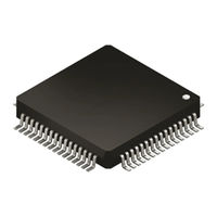
STMicroelectronics Categories
Motherboard
Microcontrollers
Computer Hardware
Controller
Control Unit
More STMicroelectronics Manuals
Login
Sign In
OR
Sign in with Facebook
Sign in with Google
Upload manual
Upload from disk
Upload from URL