Enterasys G3G170-24 Cli Reference Manual
G-series
Hide thumbs
Also See for G3G170-24:
- Hardware installation manual (59 pages) ,
- Hardware installation manual (70 pages) ,
- Quick reference (2 pages)

Subscribe to Our Youtube Channel
Related Manuals for Enterasys G3G170-24


Summary of Contents for Enterasys G3G170-24
- Page 1 Enterasys G-Series ® Ethernet Switch CLI Reference Firmware Version 1.00.xx P/N 9034358-01...
- Page 3 Notice Enterasys Networks reserves the right to make changes in specifications and other information contained in this document and its web site without prior notice. The reader should in all cases consult Enterasys Networks to determine whether any such changes have been made. The hardware, firmware, or software described in this document is subject to change without notice. IN NO EVENT SHALL ENTERASYS NETWORKS BE LIABLE FOR ANY INCIDENTAL, INDIRECT, SPECIAL, OR CONSEQUENTIAL DAMAGES WHATSOEVER (INCLUDING BUT NOT LIMITED TO LOST PROFITS) ARISING OUT OF OR RELATED TO THIS DOCUMENT, WEB SITE, OR THE INFORMATION CONTAINED IN THEM, EVEN IF ENTERASYS NETWORKS HAS BEEN ADVISED OF, KNEW OF, OR SHOULD HAVE KNOWN OF, THE POSSIBILITY OF SUCH DAMAGES. Enterasys Networks, Inc. 50 Minuteman Road Andover, MA 01810 © 2008 Enterasys Networks, Inc. All rights reserved. Part Number: 9034358‐01 March 2008 ENTERASYS, ENTERASYS NETWORKS, ENTERASYS NETSIGHT, WEBVIEW, and any logos associated therewith, are trademarks or registered trademarks of Enterasys Networks, Inc. in the United States and other countries. All other product names mentioned in this manual may be trademarks or registered trademarks of their respective companies. Documentation URL: http://www.enterasys.com/support/manuals Documentacion URL: http://www.enterasys.com/support/manuals Dokumentation im Internet: http://www.enterasys.com/support/manuals Version: Information in this guide refers to G-Series firmware version 1.00.xx...
- Page 4 ENTERASYS NETWORKS, INC. FIRMWARE LICENSE AGREEMENT BEFORE OPENING OR UTILIZING THE ENCLOSED PRODUCT, CAREFULLY READ THIS LICENSE AGREEMENT. This document is an agreement (“Agreement”) between the end user (“You”) and Enterasys Networks, Inc., on behalf of itself and its Affiliates (as hereinafter defined) (“Enterasys”) that sets forth Your rights and obligations with respect to the Enterasys software program/firmware (including any accompanying documentation, hardware or media) (“Program”) in the package and prevails over any additional, conflicting or inconsistent terms and conditions appearing on any purchase order or other document submitted by You. “Affiliate” means any person, partnership, corporation, limited liability company, other form of enterprise that directly or indirectly through one or more intermediaries, controls, or is controlled by, or is under common control with the party specified. This Agreement constitutes the entire understanding between the parties, with respect to the subject matter of this Agreement. The Program may be contained in firmware, chips or other media. BY INSTALLING OR OTHERWISE USING THE PROGRAM, YOU REPRESENT THAT YOU ARE AUTHORIZED TO ACCEPT THESE TERMS ON BEHALF OF THE END USER (IF THE END USER IS AN ENTITY ON WHOSE BEHALF YOU ARE AUTHORIZED TO ACT, “YOU” AND “YOUR” SHALL BE DEEMED TO REFER TO SUCH ENTITY) AND THAT YOU AGREE THAT YOU ARE BOUND BY THE TERMS OF THIS AGREEMENT, WHICH INCLUDES, AMONG OTHER PROVISIONS, THE LICENSE, THE DISCLAIMER OF WARRANTY AND THE LIMITATION OF LIABILITY. IF YOU DO NOT AGREE TO THE TERMS OF THIS AGREEMENT OR ARE NOT AUTHORIZED TO ENTER INTO THIS AGREEMENT, ENTERASYS IS UNWILLING TO LICENSE THE PROGRAM TO YOU AND YOU AGREE TO RETURN THE UNOPENED PRODUCT TO ENTERASYS OR YOUR DEALER, IF ANY, WITHIN TEN (10) DAYS FOLLOWING THE DATE OF RECEIPT FOR A FULL REFUND. IF YOU HAVE ANY QUESTIONS ABOUT THIS AGREEMENT, CONTACT ENTERASYS NETWORKS, LEGAL DEPARTMENT AT (978) 684‐1000. You and Enterasys agree as follows: LICENSE. You have the non‐exclusive and non‐transferable right to use only the one (1) copy of the Program ...
- Page 5 Commerce Control List, or (iii) if the direct product of the technology is a complete plant or any major component of a plant, export to Country Groups D:1 or E:2 the direct product of the plant or a major component thereof, if such foreign produced direct product is subject to national security controls as identified on the U.S. Commerce Control List or is subject to State Department controls under the U.S. Munitions List. UNITED STATES GOVERNMENT RESTRICTED RIGHTS. The enclosed Program (i) was developed solely at private expense; (ii) contains “restricted computer software” submitted with restricted rights in accordance with section 52.227‐19 (a) through (d) of the Commercial Computer Software‐Restricted Rights Clause and its successors, and (iii) in all respects is proprietary data belonging to Enterasys and/or its suppliers. For Department of Defense units, the Program is considered commercial computer software in accordance with DFARS section 227.7202‐3 and its successors, and use, duplication, or disclosure by the U.S. Government is subject to restrictions set forth herein. DISCLAIMER OF WARRANTY. EXCEPT FOR THOSE WARRANTIES EXPRESSLY PROVIDED TO YOU IN WRITING BY ENTERASYS, ENTERASYS DISCLAIMS ALL WARRANTIES, EITHER EXPRESS OR IMPLIED, INCLUDING BUT NOT LIMITED TO IMPLIED WARRANTIES OF MERCHANTABILITY, SATISFACTORY QUALITY, FITNESS FOR A PARTICULAR PURPOSE, TITLE AND NON‐INFRINGEMENT WITH RESPECT TO THE PROGRAM. IF IMPLIED WARRANTIES MAY NOT BE DISCLAIMED BY APPLICABLE LAW, THEN ANY IMPLIED WARRANTIES ARE LIMITED IN DURATION TO THIRTY (30) DAYS AFTER DELIVERY OF THE PROGRAM TO YOU. LIMITATION OF LIABILITY. IN NO EVENT SHALL ENTERASYS OR ITS SUPPLIERS BE LIABLE FOR ANY DAMAGES WHATSOEVER (INCLUDING, WITHOUT LIMITATION, DAMAGES FOR LOSS OF BUSINESS, PROFITS, BUSINESS INTERRUPTION, LOSS OF BUSINESS INFORMATION, SPECIAL, INCIDENTAL, CONSEQUENTIAL, OR RELIANCE DAMAGES, OR OTHER LOSS) ARISING OUT OF THE USE OR INABILITY TO USE THE PROGRAM, EVEN IF ENTERASYS HAS BEEN ADVISED OF THE POSSIBILITY OF SUCH DAMAGES. THIS FOREGOING LIMITATION SHALL APPLY REGARDLESS OF THE CAUSE OF ACTION UNDER WHICH DAMAGES ARE SOUGHT. THE CUMULATIVE LIABILITY OF ENTERASYS TO YOU FOR ALL CLAIMS RELATING TO THE PROGRAM, IN CONTRACT, TORT OR OTHERWISE, SHALL NOT EXCEED THE TOTAL AMOUNT OF FEES PAID TO ENTERASYS BY YOU FOR THE RIGHTS GRANTED HEREIN. AUDIT RIGHTS. You hereby acknowledge that the intellectual property rights associated with the Program are of critical value to Enterasys, and, accordingly, You hereby agree to maintain complete books, records and accounts showing (i) license fees due and paid, and (ii) the use, copying and deployment of the Program. You also grant to Enterasys and its authorized representatives, upon reasonable notice, the right to audit and examine during Your normal business hours, Your books, records, accounts and hardware devices upon which the Program may be deployed to verify compliance with this Agreement, including the verification of the license fees due and paid Enterasys and the use, copying and deployment of the Program. Enterasys’ right of examination shall be exercised reasonably, in good faith and in a manner calculated to not unreasonably interfere with Your business. In the event such audit discovers ...
- Page 6 10. ENFORCEMENT. You acknowledge and agree that any breach of Sections 2, 4, or 9 of this Agreement by You may cause Enterasys irreparable damage for which recovery of money damages would be inadequate, and that Enterasys may be entitled to seek timely injunctive relief to protect Enterasys’ rights under this Agreement in addition to any and all remedies available at law. 11. ASSIGNMENT. You may not assign, transfer or sublicense this Agreement or any of Your rights or obligations under this Agreement, except that You may assign this Agreement to any person or entity which acquires substantially all of Your stock assets. Enterasys may assign this Agreement in its sole discretion. This Agreement shall be binding upon and inure to the benefit of the parties, their legal representatives, permitted transferees, successors and assigns as permitted by this Agreement. Any attempted assignment, transfer or sublicense in violation of the terms of this Agreement shall be void and a breach of this Agreement. 12. WAIVER. A waiver by Enterasys of a breach of any of the terms and conditions of this Agreement must be in writing and will not be construed as a waiver of any subsequent breach of such term or condition. Enterasys’ failure to enforce a term upon Your breach of such term shall not be construed as a waiver of Your breach or prevent enforcement on any other occasion. 13. SEVERABILITY. In the event any provision of this Agreement is found to be invalid, illegal or unenforceable, the validity, legality and enforceability of any of the remaining provisions shall not in any way be affected or impaired thereby, and that provision shall be reformed, construed and enforced to the maximum extent permissible. Any such invalidity, illegality, or unenforceability in any jurisdiction shall not invalidate or render illegal or unenforceable such provision in any other jurisdiction. 14. TERMINATION. Enterasys may terminate this Agreement immediately upon Your breach of any of the terms and conditions of this Agreement. Upon any such termination, You shall immediately cease all use of the Program and shall return to Enterasys the Program and all copies of the Program.
-
Page 7: Table Of Contents
... 2-6 set system password aging ...2-6 set system password history ... 2-7 show system lockout ... 2-7 Setting Basic Switch Properties ... 2-8 Purpose ... 2-8 Commands ... 2-8 show ip address... 2-9 set ip address ... 2-9 clear ip address ... - Page 8 Purpose ... 2-39 Commands ... 2-39 show telnet ... 2-39 set telnet ... 2-39 telnet... 2-40 Managing Switch Configuration and Files ... 2-41 Configuration Persistence Mode ... 2-41 Purpose ... 2-41 Commands ... 2-41 show snmp persistmode ... 2-42 set snmp persistmode ... 2-42 save config ...
- Page 9 Clearing and Closing the CLI ... 2-50 Purpose ... 2-50 Commands ... 2-50 cls (clear screen) ... 2-51 exit ... 2-51 Resetting the Switch ... 2-52 Purpose ... 2-52 Commands ... 2-52 reset... 2-52 clear config ... 2-52 Using and Configuring WebView ... 2-53 Purpose ...
- Page 10 set lldp hold-multiplier ... 3-22 set lldp trap-interval ... 3-23 set lldp med-fast-repeat ... 3-23 set lldp port status ... 3-24 set lldp port trap... 3-24 set lldp port med-trap... 3-25 set lldp port location-info... 3-25 set lldp port tx-tlv ... 3-26 clear lldp ...
- Page 11 Commands ... 4-18 show flowcontrol ... 4-18 set flowcontrol... 4-19 Setting Port Link Traps and Link Flap Detection ... 4-19 Purpose ... 4-19 Commands ... 4-19 show port trap... 4-20 set port trap ... 4-20 show linkflap ... 4-21 set linkflap globalstate ... 4-23 set linkflap portstate...
- Page 12 clear port protected name... 4-50 Chapter 5: SNMP Configuration SNMP Configuration Summary ... 5-1 SNMPv1 and SNMPv2c ... 5-1 SNMPv3 ... 5-2 About SNMP Security Models and Levels ... 5-2 Using SNMP Contexts to Access Specific MIBs ... 5-3 Configuration Considerations ... 5-3 Reviewing SNMP Statistics ...
- Page 13 show newaddrtrap ... 5-29 set newaddrtrap... 5-29 show snmp notify ... 5-30 set snmp notify ... 5-31 clear snmp notify ... 5-32 show snmp notifyfilter ... 5-32 set snmp notifyfilter... 5-33 clear snmp notifyfilter... 5-34 show snmp notifyprofile ... 5-34 set snmp notifyprofile...
- Page 14 clear spantree tctrapsuppress ... 6-23 set spantree protomigration ... 6-24 show spantree spanguard ... 6-24 set spantree spanguard ... 6-25 clear spantree spanguard ... 6-26 show spantree spanguardtimeout ... 6-26 set spantree spanguardtimeout ... 6-26 clear spantree spanguardtimeout ... 6-27 show spantree spanguardlock ...
- Page 15 Chapter 7: 802.1Q VLAN Configuration VLAN Configuration Summary ... 7-1 Port String Syntax Used in the CLI ... 7-1 Creating a Secure Management VLAN ... 7-1 Viewing VLANs ... 7-2 Purpose ... 7-2 Command ... 7-3 show vlan... 7-3 Creating and Naming Static VLANs ... 7-4 Purpose ...
- Page 16 show policy profile ... 8-2 set policy profile ... 8-4 clear policy profile ... 8-5 Configuring Classification Rules ... 8-5 Purpose ... 8-5 Commands ... 8-5 show policy rule ... 8-5 show policy capability ... 8-8 set policy rule... 8-10 clear policy rule...
- Page 17 set port txq... 9-7 clear port txq... 9-8 Chapter 10: IGMP Configuration IGMP Overview ... 10-1 About IP Multicast Group Management ... 10-1 About Multicasting ... 10-2 Configuring IGMP at Layer 2 ... 10-2 Purpose ... 10-2 Commands ... 10-2 show igmpsnooping ...
- Page 18 11-12 set history ... 11-12 ping... 11-13 show users ... 11-13 disconnect ... 11-14 Managing Switch Network Addresses and Routes ... 11-15 Purpose ... 11-15 Commands ... 11-15 show arp ... 11-15 set arp... 11-16 clear arp... 11-17 traceroute ...
- Page 19 clear rmon stats ... 12-5 History Group Commands ... 12-5 Purpose ... 12-5 Commands ... 12-5 show rmon history ... 12-5 set rmon history ... 12-6 clear rmon history ... 12-7 Alarm Group Commands ... 12-7 Purpose ... 12-7 Commands ... 12-8 show rmon alarm ...
- Page 20 Configuring IP Address Pools ... 13-10 Manual Pool Configuration Considerations ... 13-10 Purpose ... 13-10 Commands ... 13-11 set dhcp pool ... 13-12 clear dhcp pool ... 13-12 set dhcp pool network... 13-13 clear dhcp pool network... 13-13 set dhcp pool hardware-address ... 13-14 clear dhcp pool hardware-address ...
- Page 21 tunnel source ... 15-8 tunnel destination ... 15-9 tunnel mode... 15-10 show interface tunnel... 15-10 Reviewing and Configuring the ARP Table ... 15-11 Purpose ... 15-11 Commands ... 15-11 show ip arp ... 15-11 arp ... 15-12 ip proxy-arp... 15-13 arp timeout...
- Page 22 ip ospf dead-interval ... 16-17 ip ospf authentication-key ... 16-18 ip ospf message digest key md5 ... 16-18 distance ospf ... 16-19 area range ... 16-20 area stub... 16-21 area default cost ... 16-21 area nssa... 16-22 area virtual-link ... 16-23 redistribute...
- Page 23 show ip pimsm neighbor ... 16-52 show ip pimsm rp... 16-52 show ip pimsm rphash ... 16-54 show ip pimsm staticrp ... 16-54 Chapter 17: IPv6 Management Purpose ... 17-1 Commands ... 17-1 show ipv6 status ... 17-1 set ipv6 ... 17-2 set ipv6 address ...
- Page 24 Chapter 19: OSPFv3 Configuration Overview ... 19-1 Default Conditions ... 19-2 Global OSPFv3 Configuration Commands ... 19-3 Purpose ... 19-3 Command ... 19-3 ipv6 router id... 19-3 ipv6 router ospf... 19-4 default-information originate ... 19-4 default-metric... 19-5 distance ospf ... 19-5 exit-overflow-interval...
- Page 25 show ipv6 ospf interface stats ... 19-38 show ipv6 ospf neighbor... 19-40 show ipv6 ospf range... 19-42 show ipv6 ospf stub table ... 19-43 show ipv6 ospf virtual-link... 19-44 Chapter 20: Security Configuration Overview of Security Methods ... 20-1 RADIUS Filter-ID Attribute and Dynamic Policy Profile Assignment ... 20-2 Configuring RADIUS ...
- Page 26 set multiauth precedence ... 20-32 clear multiauth precedence ...20-33 show multiauth port ... 20-34 set multiauth port ... 20-34 clear multiauth port ... 20-35 show multiauth station ... 20-36 show multiauth session ... 20-36 show multiauth idle-timeout ...20-37 set multiauth idle-timeout... 20-38 clear multiauth idle-timeout...
- Page 27 Abbreviating a Command ... 1-10 Example of VLAN Propagation via GVRP ... 7-20 Tables Default Settings for Basic Switch and Router Operation ... 1-2 Basic Line Editing Commands... 1-10 show system lockout Output Details... 2-7 show system Output Details ... 2-12 show version Output Details ...
- Page 28 12-2 show rmon alarm Output Details ... 12-8 12-3 show rmon event Output Details ... 12-12 14-1 Enabling the Switch for Routing ... 14-2 14-2 Router CLI Configuration Modes ... 14-2 15-1 show ip interface Output Details ... 15-5 15-2 show ip arp Output Details ...
- Page 29 19-9 show ipv6 ospf neighbor Output Details ... 19-41 19-10 show ipv6 ospf neighbor routerid Output Details... 19-42 19-11 show ipv6 ospf range Output Details ... 19-43 19-12 show ipv6 ospf stub table Output Details ... 19-43 19-13 show ipv6 ospf virtual-link Output Details ... 19-44 20-1 show radius Output Details...
- Page 30 xxviii...
-
Page 31: About This Guide
Establish and manage priority classification. • Configure IP routing and routing protocols, including RIP versions 1 and 2, OSPF, DVMRP, IRDP, and VRRP. • Configure IPv6 routing, including OSPFv3. • Configure security protocols, including 802.1X and RADIUS, SSHv2, PWA, MAC locking, and MAC authentication. • Configure access control lists (ACLs). Structure of This Guide The guide is organized as follows: Chapter 1, Introduction, provides an overview of the tasks that can be accomplished using the CLI interface, an overview of local management requirements, an overview of the device’s factory default settings, and information about using the Command Line Interface (CLI). Chapter 2, Basic Configuration, provides how to set basic system properties, how to download a firmware image, how to configure WebView and Telnet, how to manage configuration files, how to set the login password, and how to exit the CLI. Chapter 3, Discovery Protocol Configuration provides how to configure discovery protocols supported by the device. Chapter 4, Port Configuration, describes how to review and configure console port settings, and how to enable or disable switch ports and configure switch port settings, including port speed, About This Guide Important Notice Enterasys G-Series CLI Reference xxix... - Page 32 Chapter 7, 802.1Q VLAN Configuration, describes how to create static VLANs, select the mode of operation for each port, establish VLAN forwarding (egress) lists, route frames according to VLAN ID, display the current ports and port types associated with a VLAN and protocol, create a secure management VLAN, and configure ports on the device as GVRP‐aware ports. Chapter 8, Policy Classification Configuration, describes how to create, change or remove user roles or profiles based on business‐specific use of network services; how to permit or deny access to specific services by creating and assigning classification rules which map user profiles to frame filtering policies; how to classify frames to a VLAN or Class of Service (CoS); and how to assign or unassign ports to policy profiles so that only ports activated for a profile will be allowed to transmit frames accordingly. Chapter 9, Port Priority Configuration, describes how to set the transmit priority of each port and configure a rate limit for a given port and list of priorities. Chapter 10, IGMP Configuration, describes how to configure Internet Group Management Protocol (IGMP) settings for multicast filtering. Chapter 11, Logging and Network Management, describes how to configure Syslog, how to manage general switch settings, how to monitor network events and status, and how to configure SNTP and node aliases. Chapter 12, RMON Configuration, describes how to use RMON (Remote Network Monitoring), which provides comprehensive network fault diagnosis, planning, and performance tuning information and allows for interoperability between SNMP management stations and monitoring agents. Chapter 13, DHCP Server Configuration, describes how to review and configure DHCP server parameters, how to review and configure DHCP address pools, and how to display DHCP server information. Chapter 14, Preparing for Router Mode, provides information about router modes and how to activate a license. Chapter 15, IP Configuration, describes how to enable IP routing for router mode operation, how to configure IP interface settings, how to review and configure the routing ARP table, how to review and configure routing broadcasts, how to configure PIM, and how to configure IP routes. Chapter 16, IPv4 Routing Protocol Configuration, describes how to configure IPv4 routing and ...
-
Page 33: Related Documents
Square brackets with a vertical bar indicate a choice of a value. Braces with a vertical bar indicate a choice of a required value. A combination of square brackets with braces and vertical bars indicates a required choice of an optional value. Related Documents Enterasys G-Series CLI Reference xxxi... -
Page 34: Getting Help
The switch history (for example, have you returned the switch before, is this a recurring problem?) • Any previous Return Material Authorization (RMA) numbers xxxii About This Guide www.enterasys.com/support 1-800-872-8440 (toll-free in U.S. and Canada) or 1-978-684-1000 To find the Enterasys Networks Support toll-free number in your country: www.enterasys.com/support/contact/ support@enterasys.com To expedite your message, type [SWITCHING] in the subject line. -
Page 35: Chapter 1: Introduction
• Use CLI commands to perform network management and switch configuration operations. • Download a new firmware image. • Assign IP address and subnet mask. • Select a default gateway. • Establish and manage Virtual Local Area Networks (VLANs). • Establish and manage policy profiles and classifications. • Establish and manage priority classification. • Configure IPv4 routing and routing protocols, including RIP versions 1 and 2, OSPF, DVMRP, IRDP and VRRP. • Configure IPv6 routing and routing protocols, including OSPFv3. • Configure security protocols, including 802.1X and RADIUS, SSHv2, PWA, MAC locking, and MAC authentication. • Configure access control lists (ACLs). Switch Management Methods The G‐Series switch can be managed using the following methods: • Locally using a VT type terminal connected to the console port. Introduction Refer to page... Enterasys G-Series CLI Reference 1-1... -
Page 36: Factory Default Settings
• In‐band using the Enterasys NetSight • Remotely using WebView™, Enterasys Networks’ embedded web server application. The Installation Guide for your G‐Series device provides setup instructions for connecting a terminal or modem to the switch. Factory Default Settings The following tables list factory default settings available on the G‐Series switch. Table 1-1 Default Settings for Basic Switch and Router Operation Feature Switch Mode Defaults CDP discovery protocol CDP authentication code CDP hold time CDP interval Cisco discovery protocol Cisco DP hold time... - Page 37 Enabled on all ports. Port advertised ability Maximum ability advertised on all ports. Port broadcast suppression Enabled and set to limit broadcast packets to 14,881 per second on all switch ports. Port duplex mode Set to half duplex, except for 100BASE-FX and 1000BASE-X, which is set to full duplex.
- Page 38 Factory Default Settings Table 1-1 Default Settings for Basic Switch and Router Operation (Continued) Feature Rate limiting SNMP SNTP Spanning Tree Spanning Tree edge port administrative status Spanning Tree edge port delay Spanning Tree forward delay Spanning Tree hello interval...
- Page 39 Table 1-1 Default Settings for Basic Switch and Router Operation (Continued) Feature Default Setting Area NSSA (OSPF) None configured. Area range (OSPF) None configured. ARP table No permanent entries configured. ARP timeout Set to 14,400 seconds. Authentication key (RIP None configured.
-
Page 40: Using The Command Line Interface
Using the Command Line Interface Table 1-1 Default Settings for Basic Switch and Router Operation (Continued) Feature Split horizon Stub area (OSPF) Telnet Telnet port (IP) Timers (OSPF) Transmit delay (OSPF) VRRP Using the Command Line Interface Starting a CLI Session Connecting Using the Console Port Connect a terminal to the local console port as described in your G‐Series Installation Guide. The ... -
Page 41: Connecting Using Telnet
(page 2-5) to change their own passwords. Administrators with Super User (su) access can use set system login password command to change any local account password. command (page 2-3) to create and change user accounts, and the Using the Command Line Interface 1‐1. 1‐1. set password command Enterasys G-Series CLI Reference 1-7... -
Page 42: Navigating The Command Line Interface
Using the Command Line Interface Navigating the Command Line Interface Getting Help with CLI Syntax The G‐Series switch allows you to display usage and syntax information for individual commands by typing help or ? after the command. CLI Command Defaults Descriptions Each command description in this guide includes a section entitled “Defaults” which contains different information from the factory default settings on the switch described in Table section defines CLI behavior if the user enters a command without typing optional parameters (indicated by square brackets [ ]). For commands without optional parameters, the defaults section lists “None”. For commands with optional parameters, this section describes how the CLI responds if the user opts to enter only the keywords of the command syntax. Figure an example. Figure 1-2 Sample CLI Defaults Description Syntax show port status [port-string] Defaults If port‐string is not specified, status information for all ports will be displayed. ... -
Page 43: Performing A Partial Keyword Lookup
Abbreviating and Completing Commands The G‐Series switch allows you to abbreviate CLI commands and keywords down to the number of characters that will allow for a unique abbreviation. Figure show netstat command to sh net. 1‐4 shows how to use this function for all copy Port Type host Management ge.1.2 Learned ge.1.3 Learned ge.1.4 Learned ge.1.5 Learned ge.1.6 Learned ge.1.7 Learned ge.1.8 Learned ge.1.9 Learned ge.1.10 Learned Using the Command Line Interface 1‐6 shows how to abbreviate the Enterasys G-Series CLI Reference 1-9... -
Page 44: Abbreviating A Command
Using the Command Line Interface Figure 1-6 Abbreviating a Command G3(su)->sh net Active Internet connections (including servers) Proto Recv-Q Send-Q ----- ------ ------ Basic Line Editing Commands The CLI supports EMACs‐like line editing commands. Table commands. Table 1-2 Basic Line Editing Commands Key Sequence Ctrl+A Ctrl+B Ctrl+D Ctrl+E Ctrl+F Ctrl+H... -
Page 45: Chapter 2: Basic Configuration
[mask ip-mask] [gateway ip-gateway] copy tftp://tftp_server_ip_address/ filename system:image set boot system filename show version Refer to page... 2-27 2-30 2-35 2-37 2-39 2-41 2-50 2-52 2-53 Refer to page... 2-47 2-38 2-21 Enterasys G-Series CLI Reference 2-1... -
Page 46: Setting User Accounts And Passwords
Set a Syslog server IP and severity Configure and enable a RADIUS server. Configure and enable first arrival MAC locking on user ports. Setting User Accounts and Passwords Purpose To change the switch’s default user login and password settings, and to add new user accounts and passwords. Commands The commands used to configure user accounts and passwords are listed below. For information about... show system login set system login clear system login... -
Page 47: Show System Login
Number of days user passwords will remain valid before aging out. Configured with set system password aging (page Login user names. Access assigned to this user account: super-user, read-write or read-only. Whether this user account is enabled or disabled. show system login 2-7). 2-6). Enterasys G-Series CLI Reference 2-3... -
Page 48: Clear System Login
{super-user | read-write | read-only} {enable | disable} Parameters username super‐user | read‐write | read‐only enable | disable Defaults None. Mode Switch command, super user. Example This example shows how to enable a new user account with the login name “netops” with super user access privileges: G3(su)->set system login netops super-user enable clear system login Use this command to remove a local login user account. Syntax clear system login username Parameters... -
Page 49: Set Password
Please re-enter new password: ******** Password changed. G3(su)-> This example shows how a user with Read‐Write access would change his password: G3(su)->set password Please enter old password: ******** Please enter new password: ******** Please re-enter new password: ******** Password changed. G3(su)-> (Only available to users with super‐user access.) Specifies a system default or a user‐configured login account name. By default, the G‐Series switch provides the following account names: ro for Read‐Only access. rw for Read‐Write access. admin for Super User access. (This access level allows Read‐Write access to all modifiable parameters, including user accounts.) set password Enterasys G-Series CLI Reference 2-5... -
Page 50: Set System Password Length
Use this command to set the minimum user login password length. Syntax set system password length characters Parameters characters Defaults None. Mode Switch command, super user. Example This example shows how to set the minimum system password length to 8 characters: G3(su)->set system password length 8 set system password aging Use this command to set the number of days user passwords will remain valid before aging out, or to disable user account password aging. Syntax set system password aging {days | disable} Parameters... -
Page 51: Set System Password History
Use this command to display settings for locking out users after failed attempts to log in to the system. Syntax show system lockout Parameters None. Defaults None. Mode Switch command, super user. Example This example shows how to display user lockout settings. In this case, switch defaults have not been changed: G3(su)->show system lockout Lockout attempts: 3 Lockout time: Table 2‐3 provides an explanation of the command output. . Specifies the number of passwords checked for duplication. Valid values are 0 to 10. 15 minutes. set system password history Enterasys G-Series CLI Reference 2-7... -
Page 52: Setting Basic Switch Properties
Setting Basic Switch Properties Table 2-3 show system lockout Output Details Output Field Lockout attempts Lockout time Setting Basic Switch Properties Purpose To display and set the system IP address and other basic system (switch) properties. Commands The commands used to set basic system information are listed below. For information about... show ip address set ip address clear ip address show ip protocol... -
Page 53: Show Ip Address
IP. The host's gateway must exist on a different device in the network if one is configured. Syntax set ip address ip-address [mask ip-mask] [gateway ip-gateway] Parameters ip‐address Address ---------------- 10.42.13.20 Sets the IP address for the system. . show ip address Refer to page... 2-23 2-24 2-24 2-25 2-25 2-26 2-27 Mask ---------------- 255.255.0.0 Enterasys G-Series CLI Reference 2-9... -
Page 54: Clear Ip Address
Defaults If not specified, ip‐mask will be set to the natural mask of the ip‐address and ip‐gateway will be set to the ip‐address. Mode Switch command, read‐write. Usage Paramters must be entered in the order shown (host IP, then mask, then gateway) for the command to be accepted. Example This example shows how to set the system IP address to G3(su)->set ip address 10.1.10.1 mask 255.255.128.0 clear ip address Use this command to clear the system IP address. Syntax clear ip address Parameters None. Defaults None. Mode Switch command, read‐write. Example This example shows how to clear the system IP address: G3(rw)->clear ip address show ip protocol Use this command to display the method used to acquire a network IP address for switch ... -
Page 55: Set Ip Protocol
{bootp | dhcp | none} Parameters bootp dhcp none Defaults None. Mode Switch command, read‐write. Example This example shows how to set the method used to acquire a network IP address to DHCP. G3(su)->set ip protocol dhcp show system Use this command to display system information, including contact information, power and fan tray status and uptime. Syntax show system Selects BOOTP as the protocol to use to acquire the system IP address. Selects DHCP as the protocol to use to acquire the system IP address. No protocol will be used to acquire the system IP address. set ip protocol Enterasys G-Series CLI Reference 2-11... -
Page 56: Show System Output Details
Parameters None. Defaults None. Mode Switch command, read‐only. Example This example shows how to display system information: G3(su)->show system System contact: System location: System name: Power Supply 1 Status --------------------- Fan Group 1-Status ------------------ Fan Group 3-Status ------------------ Thermal Sensor -------------- Fixed Slot Power Supply Redundancy -----------------------... -
Page 57: Show System Hardware
Operational status of fan groups 1,2, and 3. Fan groupings are as follows: • Group 1 (fans 1, 2, and 3) is located in the front left of the switch to cool the Ethernet subsystem and optional 1OM module slots. -
Page 58: Show System Utilization
FirmWare Version: Boot Code Version: POWER SUPPLY 1 HARDWARE INFORMATION ----------------------------------- Model: Serial Number: Wattage: Software Version: Revision: show system utilization Use this command to display detailed information about the processor running on the switch, or the overall memory usage of the Flash and SDRAM storage devices on the unit, or the processes running on the switch. Syntax show system utilization {cpu | storage | process} Parameters storage process 2-14 Basic Configuration G3G124-24... -
Page 59: Show Time
5 sec 1 min 5 min Size(Kb) 262144 31095 5Sec 1Min 0.00% 0.00% 0.00% 0.01% 0.80% 0.22% 0.00% 0.00% 0.00% 0.00% 0.00% 0.00% show time Available (Kb) 97173 8094 5Min 0.00% 0.05% 0.20% 0.00% 0.00% 0.00% Enterasys G-Series CLI Reference 2-15... -
Page 60: Set Time
G3(su)->show time THU SEP 05 09:21:57 2002 set time Use this command to change the time of day on the system clock. Syntax set time [mm/dd/yyyy] [hh:mm:ss] Parameters [mm/dd/yyyy] [hh:mm:ss] Defaults None. Mode Switch command, read‐write. Example This example shows how to set the system clock to 7:50 a.m: G3(su)->set time 7:50:00 show summertime Use this command to display daylight savings time settings. Syntax show summertime Parameters None. Defaults None. Mode Switch command, read‐only. -
Page 61: Set Summertime
G3(su)->set summertime enable set summertime date Use this command to configure specific dates to start and stop daylight savings time. These settings will be non‐recurring and will have to be reset annually. Syntax set summertime date start_month start_date start_year start_hr_min end_month end_date end_year end_hr_min [offset_minutes] Parameters start_month start_date start_year start_hr_min end_month Enables or disables the daylight savings time function. (Optional) Applies a name to the daylight savings time settings. Specifies the month of the year to start daylight savings time. Specifies the day of the month to start daylight savings time. Specifies the year to start daylight savings time. Specifies the time of day to start daylight savings time. Format is hh:mm. Specifies the month of the year to end daylight savings time. set summertime Enterasys G-Series CLI Reference 2-17... -
Page 62: Set Summertime Recurring
Defaults If an offset is not specified, none will be applied. Mode Switch command, read‐write. Example This example shows how to set a daylight savings time start date of April 4, 2004 at 2 a.m. and an ending date of October 31, 2004 at 2 a.m. with an offset time of one hour: G3(su)->set summertime date April 4 2004 02:00 October 31 2004 02:00 60 set summertime recurring Use this command to configure recurring daylight savings time settings. These settings will start and stop daylight savings time at the specified day of the month and hour each year and will not have to be reset annually. Syntax set summertime recurring start_week start_day start_month start_hr_min end_week... -
Page 63: Clear Summertime
Use this command to modify the command prompt. Syntax set prompt prompt_string Parameters prompt_string Defaults None. Specifies a text string for the command prompt. Note: A prompt string containing a space in the text must be enclosed in quotes as shown in the example below. clear summertime Enterasys G-Series CLI Reference 2-19... -
Page 64: Show Banner Motd
Mode Switch command, read‐write. Example This example shows how to set the command prompt to Switch 1: G3(su)->set prompt “Switch 1” Switch 1(su)-> show banner motd Use this command to show the banner message of the day that will display at session login. Syntax show banner motd Parameters None. Defaults None. Mode Switch command, read‐only. Example This example shows how to display the banner message of the day: G3(rw)->show banner motd O Knights of Ni, you are just and... -
Page 65: Clear Banner Motd
\n \t -King Arthur" clear banner motd Use this command to clear the banner message of the day displayed at session login to a blank string. Syntax clear banner motd Parameters None. Defaults None. Mode Switch command, read‐write. Example This example shows how to clear the message of the day banner to a blank string: G3(rw)->clear banner motd show version Use this command to display hardware and firmware information. Refer to “Downloading a Firmware Image” on page 2‐35 for instructions on how to download a firmware image. Syntax show version Parameters None. Defaults None. clear banner motd Enterasys G-Series CLI Reference 2-21... -
Page 66: Set System Name
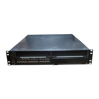
Mode Switch command, read‐only. Example This example shows how to display version information. Please note that you may see different information displayed, depending on the type of hardware. G3(su)->show version Copyright (c) 2007 by Enterasys Networks, Inc. Boot promt:01.00.38 Slot Port Model ---- --- ---- G3G170-24 Table 2‐5 provides an explanation of the command output. Table 2-5 show version Output Details Output Field Slot Port Model Serial #... -
Page 67: Set System Location
(Optional) Specifies a text string that contains the name of the person to contact for system administration. Note: A contact string containing a space in the text must be enclosed in quotes as shown in the example below. set system location Enterasys G-Series CLI Reference 2-23... -
Page 68: Set Width
Mode Switch command, read‐write. Example This example shows how to set the system contact string: G3(su)->set system contact “Joe Smith” set width Use this command to set the number of columns for the terminal connected to the switch’s console port. Syntax set width screenwidth [default] Parameters screenwidth default Defaults None. Mode Switch command, read‐write. Usage The number of rows of CLI output displayed is set using the set length command as described in “set length” on page 2‐24. Example This example shows how to set the terminal columns to 50: G3(su)->set width 50 set length Use this command to set the number of lines the CLI will display. This command is persistent (written to NV‐RAM). Syntax... -
Page 69: Show Logout
Use this command to display the time (in seconds) an idle console or Telnet CLI session will remain connected before timing out. Syntax show logout Parameters None. Defaults None. Mode Switch command, read‐only. Example This example shows how to display the CLI logout setting: G3(su)->show logout Logout currently set to: 10 minutes. set logout Use this command to set the time (in minutes) an idle console or Telnet CLI session will remain connected before timing out. Syntax set logout timeout Sets the number of lines in the CLI display. Valid values are 0, which disables the scrolling screen feature described in “Displaying Scrolling Screens” on page 1‐9, and from 5 to 512. show logout Enterasys G-Series CLI Reference 2-25... -
Page 70: Show Console
Parameters timeout Defaults None. Mode Switch command, read‐write. Example This example shows how to set the system timeout to 10 minutes: G3(su)->set logout 10 show console Use this command to display console settings. Syntax show console [baud] [bits] [flowcontrol] [parity] [stopbits] Parameters baud bits flowcontrol parity stopbits Defaults If no parameters are specified, all settings will be displayed. Mode Switch command, read‐only. Example This example shows how to display all console settings: G3(su)->show console Baud Flow... -
Page 71: Set Console Baud
Enterasys Customer Portal or contact the Enterasys Networks Sales Department. License Key Field Descriptions When Enterasys supplies a license, it will be sent to you as a character string similar to the following: INCREMENT g3advrouter 2006.0127 27-jan-2011 0123456789AB 0123456789AB The contents of the six fields, from the left, indicate: • Type—the type of license. For the G‐Series, the value in this field is always “INCREMENT.” • Feature—description of the feature being licensed. For example, ”g3advrouter”as shown in the character string above. • Date‐based version (DBV)—a date‐related string. For the G‐Series, the value in this field is not significant. • Expiration type—indicates whether the license is a permanent or an evaluation license. If the license is an evaluation license, this field will contain the expiration date of the license. If the license is a permanent license, this field will contain the word “permanent.” • Key—the license key. • Host ID—the serial number of the switch to which this license applies. Sets the console baud rate. Valid values are: 300, 600, 1200, 2400, 4800, 5760, 9600, 14400, 19200, 38400, and 115200. set console baud Enterasys G-Series CLI Reference 2-27... -
Page 72: Clearing, Showing, And Moving Licenses
Clearing, Showing, and Moving Licenses Licenses can be displayed, applied, and cleared only with the license commands described in this chapter. General configuration commands such as show config or clear config do not apply to licenses. Every license is associated with a specific hardware platform, based on the serial number of the hardware platform. If you need to move a license from one hardware platform to another, you must contact Enterasys Customer Support to arrange for re‐hosting of the license. Commands The commands used to activate and verify licensed features are listed below. For information about... set license show license clear license set license Use this command to activate the G‐Series licensed features. Syntax set license type feature DBV expiration key hostid Parameters type feature expiration... -
Page 73: Show License
Use this command to display license key information for switches with activated licenses. Syntax show license Parameters Defaults Mode Switch command, read‐only. Usage Licenses can be displayed, applied, and cleared only with the license commands described in this chapter. General configuration commands such as show config or clear config do not affect licenses. Example This example shows how to display license key information . G3(ro)->show license key: INCREMENT status: Active clear license Use this command to clear the license key settings. Syntax clear license featureId feature 2006.0728 permanent 31173CAC6495 045100039001 show license Enterasys G-Series CLI Reference 2-29... -
Page 74: Configuring System Power And Power Over Ethernet (Poe)
Configuring System Power and Power over Ethernet (PoE) Parameters featureID feature Defaults None. Mode Switch command, read‐write. Example This example shows how to clear the Advanced Routing licensed feature: G3(rw)->clear license featureId g3advrouter Configuring System Power and Power over Ethernet (PoE) Some commands in this section apply only to PoE-equipped G-Series devices. Consult the Installation Guide shipped with your product to determine if it is PoE-equipped. -
Page 75: Show Inlinepower
Parameters redundant non‐redundant Defaults None. Mode Switch command, read‐write. Example This example shows how to set the system power redundancy mode to non‐redundant: G3(su)->set system power non-redundant show inlinepower Use this command to display system power properties. Syntax show inlinepower Parameters None. Defaults None. Mode Switch command, read‐only. Sets the system to operate in redundant power mode. This is the default setting when two power supplies are installed. Sets the system to operate in non‐redundant power mode when two power supplies are installed. show inlinepower Enterasys G-Series CLI Reference 2-31... -
Page 76: Set Inlinepower Threshold
set inlinepower threshold Examples This example shows how to display system power properties. In this case, power redundancy is set to redundant mode: G3(su)->show inlinepower Detection Mode Total Power Detected Total Power Available Total Power Assigned Power Allocation Mode Power Trap Status Power Redundancy Status: redundant Power Supply 1 Status Power Supply 2 Status Slot Status ---- ------ auto auto... -
Page 77: Set Inlinepower Trap
{disable | enable} module-number Parameters disable | enable module‐number Mode Switch command, read‐write. Example This example shows how to enable inline power trap messaging on module 1: G3(su)->set inlinepower trap enable 1 show port inlinepower Use this command to display all ports supporting PoE. Syntax show port inlinepower [port-string] Parameters port‐string Defaults If not specified, information for all PoE ports will be displayed. Disables or enables inline power trap messaging. Specifies the module on which to disable or enable trap messaging. (Optional) Displays information for specific PoE port(s). set inlinepower trap or module Enterasys G-Series CLI Reference 2-33... -
Page 78: Set Port Inlinepower
Mode Switch command, read‐only. Example This example shows how to display PoE information for port administrative state, PoE priority and class have not been changed from default values: G3(su)->show port inlinepower ge.2.1 Port Type ---- ---- ge.2.1 wireless set port inlinepower Use this command to configure PoE parameters on one or more ports. Syntax set port inlinepower port-string {[admin {off | auto}] [priority {critical | high | low}] [type type]} Parameters port‐string... -
Page 79: Downloading A Firmware Image
1 - Start operational code. 2 - Start Boot Menu. Select (1, 2):2 Password: ************* Before the boot up completes, type 2 to select “Start Boot Menu”. Use “administrator” for the Password. Note: The “Boot Menu” password “administrator” can be changed using boot menu option 11. Downloading a Firmware Image Enterasys G-Series CLI Reference 2-35... - Page 80 Ready to RECEIVE File xcode.bin in binary mode Send several Control-X characters to cCKCKCKCKCKCKCK XMODEM transfer complete, checking CRC... Verified operational code CRC. The following Enterasys Header is in the image: MD5 Checksum...fe967970996c4c8c43a10cd1cd7be99a Boot File Identifier...0x0517 Header Version...0x0100 Image Type...0x82 Image Offset...0x004d...
-
Page 81: Reverting To A Previous Image
Reviewing and Selecting a Boot Firmware Image Purpose To display and set the image file the switch loads at startup. The G3 switch allows you to download and store a backup image, which can be selected as the startup image by using the commands described in this section. Commands The commands used to review and select the switch’s boot image file are listed below. For information about... show boot system set boot system show boot system Use this command to display the firmware image the switch loads at startup. Reviewing and Selecting a Boot Firmware Image Refer to page... 2-37 2-38 Enterasys G-Series CLI Reference 2-37... -
Page 82: Set Boot System
Syntax show boot system Parameters None. Defaults None. Mode Switch command, read‐only. Example This example shows how to display the switch’s boot firmware image: G3(su)->show boot system Current system image to boot: bootfile set boot system Use this command to set the firmware image the switch loads at startup. Syntax set boot system filename Parameters filename Defaults None. Mode Switch command, read‐write. Example This example shows how to set the boot firmware image file to “newimage”:... -
Page 83: Starting And Configuring Telnet
G3(su)->show telnet Telnet inbound is currently: ENABLED Telnet outbound is currently: ENABLED set telnet Use this command to enable or disable Telnet on the switch. Syntax set telnet {enable | disable} [inbound | outbound | all] Starting and Configuring Telnet Refer to page... 2-39 2-39 2-40 Enterasys G-Series CLI Reference 2-39... -
Page 84: Telnet
Parameters enable | disable inbound | outbound | all Defaults If not specified, both inbound and outbound Telnet service will be enabled. Mode Switch command, read‐write. Example This example shows how to disable inbound and outbound Telnet services: G3(su)->set telnet disable all Disconnect all telnet sessions and disable now (y/n)? [n]: y All telnet sessions have been terminated, telnet is now disabled. telnet Use this command to start a Telnet connection to a remote host. The G‐Series switch allows a total of four inbound and / or outbound Telnet session to run simultaneously. Syntax telnet host [port]... -
Page 85: Managing Switch Configuration And Files
Managing Switch Configuration and Files Refer to page... 2-42 2-42 2-43 2-43 2-44 2-45 2-46 2-47 2-47 2-48 2-48 Enterasys G-Series CLI Reference 2-41... -
Page 86: Show Snmp Persistmode
Use this command to display the configuration persistence mode setting. Syntax show snmp persistmode Parameters None. Defaults None. Mode Switch command, read‐only. Usage By default, the mode is set to “auto save,” which automatically saves configuration changes at specific intervals. If the mode is set to “manual,” configuration commands are never automatically saved. In order to make configuration changes persistent when the mode is manual, the save config command must be issued as described in “Configuration Persistence Mode” on page 2‐41. Example This example shows how to display the configuration persistence mode setting. In this case, persistence mode is set to “manual”, which means configuration changes are not being automatically saved. G3(su)->show snmp persistmode persistmode is manual set snmp persistmode Use this command to set the configuration persistence mode, which determines whether user‐... -
Page 87: Save Config
Switch command, read‐write. Example This example shows how to set the configuration persistence mode to manual: G3(su)->set snmp persistmode manual save config Use this command to save the running configuration. Syntax save config Parameters None. Defaults None. Mode Switch command, read‐write. Example This example shows how to save the running configuration: G3(su)->save config Use this command to list configuration and image files stored in the file system. Syntax dir [filename] Sets the configuration persistence mode to automatic. This is the default state. Sets the configuration persistence mode to manual. In order to make configuration changes persistent, the save config command must be issued as described in “save config” on page 2‐43. This mode is useful for reverting back to old configurations. save config Enterasys G-Series CLI Reference 2-43... -
Page 88: Show File
Parameters filename Defaults If filename is not specified, all files in the system will be displayed. Mode Switch command, read‐only. Example This example shows how to list all the configuration and image files in the system: G3(su)->dir Images: ================================================================== Filename: Version: Size: Date: CheckSum: Compatibility: G3G124-24, G3G124-24P Filename: Version: Size: Date: CheckSum: Compatibility: G3G124-24, G3G124-24P Files: ================================ ======== configs: Monday.cfg admin1.cfg logs: current.log show file Use this command to display the contents of a file. -
Page 89: Show Config
15 : set policy port ge.1.2 4 show config Use this command to display the system configuration or write the configuration to a file. Syntax show config [all | facility] [outfile {configs/filename}] Parameters facility outfile configs/filename Defaults By default, show config will display all non‐default configuration information for all facilities. Mode Switch command, read‐only. (Optional) Displays default and non‐default configuration settings. (Optional) Specifies the exact name of one facility for which to show configuration. For example, enter “router” to show only router configuration. (Optional) Specifies that the current configuration will be written to a text file in the configs/ directory. Specifies a filename in the configs/ directory to display. show config Enterasys G-Series CLI Reference 2-45... -
Page 90: Configure
G3(rw)->show config port This command shows non-default configurations only. Use 'show config all' to show both default and non-default configurations. begin #***** NON-DEFAULT CONFIGURATION ***** #port set port jumbo disable ge.1.1 configure Use this command to execute a previously downloaded configuration file stored on the switch. Syntax configure filename [append] Parameters filename append Defaults If append is not specified, the current running configuration will be replaced with the contents of ... -
Page 91: Copy
Parameters source destination Defaults None. Mode Switch command, read‐write. Examples This example shows how to download an image via TFTP: G3(su)->copy tftp://10.1.192.34/version01000 system:image This example shows how to download a configuration file to the configs directory: G3(su)->copy tftp://10.1.192.1/Jan1_2004.cfg configs/Jan1_2004.cfg delete Use this command to remove an image or a CLI configuration file from the switch. Syntax delete filename Parameters filename Defaults None. Specifies location and name of the source file to copy. Options are a local file path in the configs directory, or the URL of a TFTP server. Specifies location and name of the destination where the file will be copied. Options are a slot location and file name, or the URL of a TFTP server. Specifies the local path name to the file. Valid directories are /images and /configs.44. copy Enterasys G-Series CLI Reference 2-47... -
Page 92: Show Tftp Settings
Mode Switch command, read‐write. Usage Use the dir command (page 2‐43) to display current image and configuration file names. Example This example shows how to delete the “Jan1_2004.cfg” configuration file: G3(su)->delete configs/Jan1_2004.cfg show tftp settings Use this command to display TFTP settings used by the switch during data transfers using TFTP. Syntax show tftp settings Parameters None. Defaults None. Mode Switch command, read‐only. Usage The TFTP timeout value can be set with the set tftp timeout command. The TFTP retry value can be set with the set tftp retry command. Example This example shows the output of this command. G3(ro)->show tftp settings TFTP packet timeout (seconds): 2 TFTP max retry: 5 set tftp timeout Use this command to configure how long TFTP will wait for a reply of either an acknowledgement ... -
Page 93: Clear Tftp Timeout
Syntax clear tftp timeout Parameters None. Defaults None. Mode Switch command, read‐write. Example This example shows how to clear the timeout value to the default of 2 seconds. G3(rw)-> clear tftp timeout set tftp retry Use this command to configure how many times TFTP will resend a packet, either an acknowledgement packet or a data packet. Syntax set tftp retry retry Parameters retry Specifies the number of seconds to wait for a reply. The valid range is from 1 to 30 seconds. Default value is 2 seconds. Specifies the number of times a packet will be resent. The valid range is from 1 to 1000. Default value is 5 retries. clear tftp timeout Enterasys G-Series CLI Reference 2-49... -
Page 94: Clear Tftp Retry
Defaults None. Mode Switch command, read‐write. Example This example sets the retry count to 3. G3(rw)->set tftp retry 3 clear tftp retry Use this command to reset the TFTP retry value to the default value of 5 retries. Syntax clear tftp retry Parameters None. Defaults None. Mode Switch command, read‐write. Example This example shows how to clear the retry value to the default of 5 retries. G3(rw)-> clear tftp retry Clearing and Closing the CLI Purpose To clear the CLI screen or to close your CLI session. -
Page 95: Cls (Clear Screen)
(clear screen) Use this command to clear the screen for the current CLI session. Syntax Parameters None Defaults None. Mode Switch command, read‐only. Example This example shows how to clear the CLI screen: G3(su)->cls exit Use either of these commands to leave a CLI session. Syntax exit Parameters None. Defaults None. Mode Switch command, read‐only. Usage By default, switch timeout occurs after 15 minutes of user inactivity, automatically closing your CLI session. Use the set logout command (page 2‐25) to change this default. Example This example shows how to exit a CLI session: G3(su)->exit cls (clear screen) Enterasys G-Series CLI Reference 2-51... -
Page 96: Resetting The Switch
Resetting the Switch Resetting the Switch Purpose To reset one or more switches, and to clear the user‐defined configuration parameters. Commands For information about... reset clear config reset Use this command to reset the switch without losing any user‐defined configuration settings. Syntax reset Parameters None. Defaults None. Mode Switch command, read‐write. Examples This example shows how to reset the system: G3(su)->reset This command will reset all modules and may disconnect your telnet session. -
Page 97: Using And Configuring Webview
To use WebView, type the IP address of the switch in your browser. To use WebView over SSL, type in https:// then the IP address of the switch. For example, https://172.16.2.10. Commands For information about... show webview set webview show ssl set ssl show webview Use this command to display WebView status. Syntax show webview Parameters None. Defaults None. Using and Configuring WebView Refer to page... 2-53 2-54 2-54 2-55 Enterasys G-Series CLI Reference 2-53... -
Page 98: Set Webview
Mode Switch command, read‐only. Example This example shows how to display WebView status: G3(rw)->show webview WebView is Enabled. set webview Use this command to enable or disable WebView on the switch. Syntax set webview {enable | disable} Parameters enable | disable Defaults None. Mode Switch command, read‐write. Usage It is good practice for security reasons to disable HTTP access on the switch when finished configuring with WebView, and then to only enable WebView on the switch when changes need to be made. Example This example shows how to disable WebView on the switch: G3(rw)->set webview disable show ssl Use this command to display SSL status. Syntax show ssl Parameters None. -
Page 99: Set Ssl
SSL status: Enabled set ssl Use this command to enable or disable the use of WebView over SSL port 443. By default, SSL is disabled on the switch. This command can also be used to reinitialize the hostkey that is used for encryption. Syntax set ssl {enabled | disabled | reinitialize | hostkey reinitialize} Parameters enabled | disabled reinitialize hostkey reinitialize Defaults None. Mode Switch command, read‐write. Example This example shows how to enable SSL: G3(rw)->set ssl enabled Enable or disable the ability to use WebView over SSL. Stops and then restarts the SSL process. Stops SSL, regenerates new keys, and then restarts SSL. set ssl Enterasys G-Series CLI Reference 2-55... - Page 100 set ssl 2-56 Basic Configuration...
-
Page 101: Purpose
For information about... show cdp set cdp state set cdp auth set cdp interval set cdp hold-time clear cdp show neighbors show cdp Use this command to display the status of the CDP discovery protocol and message interval on one or more ports. Discovery Protocol Configuration Refer to page... 3-13 Refer to page... Enterasys G-Series CLI Reference 3-1... -
Page 102: Show Cdp Output Details
For details, refer to state” on page 3-3. CDP version number(s) supported by the switch. Minimum time interval (in seconds) at which CDP configuration messages can be set. The default of 180 seconds can be reset with the set cdp hold-time command. -
Page 103: Set Cdp State
Port designation. For a detailed description of possible port-string values, refer to “Port String Syntax Used in the CLI” on page 4-1. Whether CDP is enabled, disabled or auto-enabled on the port. Auto‐enables, disables or enables the CDP protocol on the specified port(s). In auto‐enable mode, which is the default mode for all ports, a port automatically becomes CDP‐enabled upon receiving its first CDP message. (Optional) Enables or disables CDP on specific port(s). For a detailed description of possible port‐string values, refer to “Port String Syntax Used in the CLI” on page 4‐1. set cdp state .1.2: .1.2: Enterasys G-Series CLI Reference 3-3 “set... -
Page 104: Set Cdp Interval
Parameters auth‐code Defaults None. Mode Switch command, read‐write. Usage The authentication code value determines a switch’s CDP domain. If two or more switches have the same CDP authentication code, they will be entered into each other’s CDP neighbor tables. If they have different authentication codes, they are in different domains and will not be entered into each other’s CDP neighbor tables. A switch with the default authentication code (16 null characters) will recognize all switches, no matter what their authentication code, and enter them into its CDP neighbor table. Example This example shows how to set the CDP authentication code to 1,2,3,4,5,6,7,8: G3(su)->set cdp auth 1,2,3,4,5,6,7,8: set cdp interval Use this command to set the message interval frequency (in seconds) of the CDP discovery protocol. Syntax set cdp interval frequency Parameters frequency Defaults None. Mode Switch command, read‐write. Example This example shows how to set the CDP interval frequency to 15 seconds: G3(su)->set cdp interval 15... -
Page 105: Set Cdp Hold-Time
Syntax clear cdp {[state] [port-state port-string] [interval] [hold-time] [auth-code]} Parameters state port‐state port‐string interval hold‐time auth‐code Defaults At least one optional parameter must be entered. Mode Switch command, read‐write. Example This example shows how to reset the CDP state to auto‐enabled: G3(su)->clear cdp state Specifies the hold time value for CDP messages in seconds.Valid values are from 15 to 600. (Optional) Resets the global CDP state to auto‐enabled. (Optional) Resets the port state on specific port(s) to auto‐enabled. (Optional) Resets the message frequency interval to 60 seconds. (Optional) Resets the hold time value to 180 seconds. (Optional) Resets the authentication code to 16 bytes of 00 (00‐00‐00‐ 00‐00‐00‐00‐00). set cdp hold-time Enterasys G-Series CLI Reference 3-5... -
Page 106: Show Neighbors
This command displays Neighbor Discovery information for either the CDP or Cisco DP protocols. Syntax show neighbors [port-string] Parameters port‐string Defaults If no port is specified, all Neighbor Discovery information is displayed. Mode Switch command, read‐only. Usage This command displays information discovered by both the CDP and the Cisco DP protocols. Example This example displays Neighbor Discovery information for all ports. G3(su)->show neighbors Port Device ID ------------------------------------------------------------------------------ ge.1.1 00036b8b1587 ge.1.6 0001f496126f ge.1.6 00-01-f4-00-72-fe ge.1.6 00-01-f4-00-70-8a ge.1.6 00-01-f4-c5-f7-20 ge.1.6 00-01-f4-89-4f-ae ge.1.6 00-01-f4-5f-1f-c0 ge.1.19... -
Page 107: Commands
Whether Cisco DP is globally enabled or disabled. Auto indicates that Cisco DP will be globally enabled only if Cisco DP PDUs are received. Default setting of auto-enabled can be reset with the set ciscodp status command. show ciscodp Refer to page... 3-10 3-10 3-12 Enterasys G-Series CLI Reference 3-7... -
Page 108: Show Ciscodp Port Info
Number of seconds neighboring devices will hold PDU transmissions from the sending device. Default value of 180 can be changed with the set ciscodp holdtime command. The MAC address of the switch. The time that the last Cisco DP neighbor was discovered. (Optional) Displays Cisco DP information for a specific port. For a detailed ... -
Page 109: Set Ciscodp Status
The trust mode of the port. Default of trusted can be changed using the set ciscodp port command. The Class of Service priority value for untrusted traffic. The default of 0 can be changed using the set ciscodp port command. Globally enable only if Cisco DP PDUs are received. Globally disable Cisco discovery protocol. Globally enable Cisco discovery protocol. Specifies the number of seconds between Cisco DP PDU transmissions. Valid values are from 5 to 254 seconds. set ciscodp status Enterasys G-Series CLI Reference 3-9... -
Page 110: Set Ciscodp Holdtime
Mode Switch command, read‐write. Example This example shows how to set the Cisco DP timer to 120 seconds. G3(su)->set ciscodp timer 120 set ciscodp holdtime Use this command to set the time to live (TTL) for Cisco discovery protocol PDUs. This is the amount of time, in seconds, neighboring devices will hold PDU transmissions from the sending device. Syntax set ciscodp holdtime hold-time Parameters hold‐time Defaults None. Mode Switch command, read‐write. Example This example shows how to set Cisco DP hold time to 180 seconds: G3(su)->set ciscodp hold-time 180 set ciscodp port Use this command to set the status, voice VLAN, extended trust mode, and CoS priority for untrusted traffic for the Cisco Discovery Protocol on one or more ports. Syntax... - Page 111 • Voice VLAN: none • Trust mode: trusted • CoS value: 0 Mode Switch mode, read‐write. Usage The following points describe how the Cisco DP extended trust settings work on the switch. • A Cisco DP port trust status of trusted or untrusted is only meaningful when a Cisco IP phone is connected to a switch port and a PC or other device is connected to the back of the Cisco IP phone. • A Cisco DP port state of trusted or untrusted only affects tagged traffic transmitted by the device connected to the Cisco IP phone. Untagged traffic transmitted by the device connected to the Cisco IP phone is unaffected by this setting. • If the switch port is configured to a Cisco DP trust state of trusted (with the trusted yes parameter of this command), this setting is communicated to the Cisco IP phone instructing it to allow the device connected to it to transmit traffic containing any CoS or Layer 2 802.1p marking. • If the switch port is configured to a Cisco DP trust state of untrusted (trusted no), this setting is communicated to the Cisco IP phone instructing it to overwrite the 802.1p tag of traffic transmitted by the device connected to it to 0, by default, or to the value specified by the cos parameter of this command. • There is a one‐to‐one correlation between the value set with the cos parameter and the 802.1p value assigned to ingressed traffic by the Cisco IP phone. A value of 0 equates to an 802.1p priority of 0. Therefore, a value of 7 is given the highest priority. set ciscodp port Enterasys G-Series CLI Reference 3-11...
-
Page 112: Clear Ciscodp
[status | timer | holdtime | {port {status | vvid | trust | cos} [port-string]}] Parameters status timer holdtime port status vvid trust port‐string Defaults If no parameters are entered, all Cisco DP parameters are reset to the defaults globally and for all ports. Mode Switch mode, read‐write. Examples This example shows how to clear all the Cisco DP parameters back to the default settings. G3(rw)->clear ciscodp This example shows how to clear the Cisco DP status on port G3(rw)->clear ciscodp port status ge.1.5 3-12 Discovery Protocol Configuration Clears global CiscoDP enable status to default of auto. Clears the time between CiscoDP PDU transmissions to default of 60 seconds. Clears the time‐to‐live for CiscoDP PDU data to default of 180 seconds. Clears the CiscoDP port configuration. Clears the individual port operational status to the default of enabled. Clears the individual port voice VLAN for CiscoDP PDU transmission to 0. -
Page 113: Configuring Link Layer Discovery Protocol And Lldp-Med
Configuring Link Layer Discovery Protocol and LLDP-MED Refer to page... 3-14 3-15 3-16 3-16 3-17 3-17 Enterasys G-Series CLI Reference 3-13... -
Page 114: Configuration Tasks
show lldp For information about... show lldp port remote-info set lldp tx-interval set lldp hold-multiplier set lldp trap-interval set lldp med-fast-repeat set lldp port status set lldp port trap set lldp port med-trap set lldp port location-info set lldp port tx-tlv clear lldp clear lldp port status clear lldp port trap... -
Page 115: Show Lldp Port Status
: ge.1.1-60; ge.2.1-24; ge.3.1-30; ge.4.1-12; : ge.1.1-60; ge.2.1-24; ge.3.1-30; ge.4.1-12; : ge.1.1-60; ge.2.1-24; ge.3.1-30; ge.4.1-12; : ge.1.1-60; ge.2.1-24; ge.3.1-30; ge.4.1-12; (Optional) Displays LLDP status for one or a range of ports. : ge.1.1-60; ge.2.1-24; ge.3.1-30; ge.4.1-12 : ge.1.1-60; ge.2.1-24; ge.3.1-30; ge.4.1-12 show lldp port status Enterasys G-Series CLI Reference 3-15... -
Page 116: Show Lldp Port Trap
Use this command to display the ports that are enabled to send an LLDP notification when a remote system change has been detected or an LLDP‐MED notification when a change in the topology has been sensed. Ports are enabled to send LLDP notifications with the set lldp port trap command and to send LLDP‐MED notifications with the set lldp port med‐trap command. Syntax show lldp port trap [port-string] Parameters port‐string Defaults If port‐string is not specified, LLDP port trap information will be displayed for all ports. Mode Switch command, read‐only. Example This example shows how to display LLDP port trap information for all ports. G3(ro)->show lldp port trap Trap-Enabled Ports MED Trap-Enabled Ports: show lldp port tx-tlv Use this command to display information about which optional TLVs have been configured to be transmitted on ports. Ports are configured to send optional TLVs with the set lldp port tx‐tlv command. Syntax show lldp port tx‐tlv [port‐string] Parameters port‐string... -
Page 117: Show Lldp Port Location-Info
Sys Mgmt Vlan Pro (Optional) Displays port location information for one or a range of ports. Location ------------------------- 1234567890 1234567890 1234567890 show lldp port location-info MAC PoE Link Max MED MED MED MED Aggr Frame Cap Pol Loc PoE --- --- --- --- Enterasys G-Series CLI Reference 3-17... - Page 118 Mgmt Addr : 10.21.64.100 Chassis ID : 00-E0-63-93-74-A5 Sys Name : LLDP PoE test Chassis Sys Desc : Enterasys Networks, Inc. Sys Cap Supported/Enabled Auto-Neg Supported/Enabled Auto-Neg Advertised Operational Speed/Duplex/Type : 100 full tx Max Frame Size (bytes) Vlan Id LAG Supported/Enabled/Id Protocol Id : Spanning Tree v-3 (IEEE802.1s)
-
Page 119: Show Lldp Port Local-Info Output Details
LLDP-MED Extensions Extended Power via MDI TLV. Displayed only when a port has PoE capabilities. Value is the Power Type of the device. On a switch port, the value is Power Sourcing Entity (PSE). PoE Power Source LLDP-MED Extensions Extended Power via MDI TLV. Displayed only when a port has PoE capabilities. -
Page 120: Show Lldp Port Remote-Info
Parameters port‐string Defaults If port‐string is not specified, remote system information will be displayed for all ports. Mode Switch command, read‐only. 3-20 Discovery Protocol Configuration What it Displays... IEEE 802.3 Extensions Power via MDI TLV. Displayed only when a port has PoE capabilities. Indicates whether pair selection can be controlled on the given port (refer to RFC 3621). Value for Controllable can be true or false. -
Page 121: Show Lldp Port Remote-Info Output Display
Remote Port Id : 00-09-6e-0e-14-3d : bridge,telephone/bridge : yes/yes : 10BASE-T, 10BASE-TFD : 100BASE-TX, 100BASE-TXFD : pause, Spause : 4610D01A : b10d01b2_7.bin : a10d01b2_7.bin : 05GM42004348 : Avaya : 4610 show lldp port remote-info .3.1. The Enterasys G-Series CLI Reference 3-21... -
Page 122: Set Lldp Tx-Interval
Use this command to set the time, in seconds, between successive LLDP frame transmissions initiated by changes in the LLDP local system information. Syntax set lldp tx-interval frequency Parameters frequency Defaults None. Mode Switch command, read‐write. Example This example sets the transmit interval to 20 seconds. G3(rw)->set lldp tx-interval 20 set lldp hold-multiplier Use this command to set the time‐to‐live value used in LLDP frames sent by this device. The time‐ to‐live for LLDPDU data is calculated by multiplying the transmit interval by the hold multiplier value. Syntax set lldp hold-multiplier multiplier-val Parameters multiplier‐val Defaults None. -
Page 123: Set Lldp Trap-Interval
Switch command, read‐write. Example This example sets the minimum interval between LLDP traps to 10 seconds. G3(rw)->set lldp trap-interval 10 set lldp med-fast-repeat Network connectivity devices transmit only LLDP TLVs in LLDPDUs until they detect that an LLDP‐MED endpoint device has connected to a port. At that point, the network connectivity device starts sending LLDP‐MED TLVs at a fast start rate on that port. Use this command to set the number of successive LLDPDUs (with LLDP‐MED TLVs) to be sent for one complete fast start interval. Syntax set lldp med-fast-repeat count Parameters count Defaults None. Mode Switch command, read‐write. Specifies the minimum time between LLDP trap transmissions, in seconds. The value can range from 5 to 3600 seconds. The default value is 5 seconds. Specifies the number of fast start LLDPDUs to be sent when an LLDP‐MED endpoint device is detected. Value can range from 1 to 10. Default is 3. set lldp trap-interval Enterasys G-Series CLI Reference 3-23... -
Page 124: Set Lldp Port Status
{tx-enable | rx-enable | both | disable} port-string Parameters tx‐enable rx‐enable both disable port‐string Defaults None. Mode Switch command, read‐write. Example This example enables both transmitting LLDPDUs and receiving and processing LLDPDUs from remote systems on ports G3(rw)->set lldp port status both ge.1.1-6 set lldp port trap Use this command to enable or disable sending LLDP notifications (traps) when a remote system change is detected. Syntax set lldp port trap {enable | disable} port-string... -
Page 125: Set Lldp Port Med-Trap
Switch command, read‐write. Example This example enables transmitting LLDP‐MED traps on ports G3(rw)->set lldp port med-trap enable ge.1.1-6 set lldp port location-info Use this command to configure LLDP‐MED location information on a port or range of ports. Currently, only Emergency Call Services (ECS) Emergency Location Identification Number (ELIN) is supported. Syntax set lldp port location-info elin elin-string port-string .1.1 through Enables transmitting LLDP‐MED traps on the specified ports. Disables transmitting LLDP‐MED traps on the specified ports. Specifies the port or range of ports to be affected. set lldp port med-trap .1.6. .1.1 through .1.6. Enterasys G-Series CLI Reference 3-25... -
Page 126: Set Lldp Port Tx-Tlv
Parameters elin elin‐string port‐string Defaults None. Mode Switch command, read‐write. Example After you configure a location information value, you must also configure the port to send the Location Information TLV with the set lldp port tx‐tlv command. This example configures the ELIN identifier 5551234567 on ports the Location Information TLV. G3(rw)->set lldp port location-info 5551234567 ge.1.1-6 G3(rw)->set lldp port tx-tlv med-loc ge.1.1-6 set lldp port tx-tlv Use this command to select the optional LLDP and LLDP‐MED TLVs to be transmitted in LLDPDUs by the specified port or ports. Use the show lldp port local‐info command to display the values of these TLVs for the port. Syntax set lldp port tx-tlv {[all] | [port-desc] [sys-name] [sys-desc] [sys-cap] [mgmt-... - Page 127 LACP information defined by Protocol Identity IEEE 802.1 Extensions TLV. If LACP is enabled on the port, value sent includes version of protocol being used. GVRP information defined by Protocol Identity IEEE 802.1 Extensions TLV. If LACP is enabled on the port, value sent includes version of protocol being used. MAC‐PHY Configuration/Status IEEE 802.3 Extensions TLV. Value sent includes the operational MAU type, duplex, and speed of the port. Power via MDI IEEE 802.3 Extensions TLV. Values sent include whether pair selection can be controlled on port, and the power class supplied by the port. Only valid for PoE‐enabled ports. Link Aggregation IEEE 802.3 Extensions TLV. Values sent indicate whether the link associated with this port can be aggregated, whether it is currently aggregated, and if aggregated, the aggregated port identifier. Maximum Frame Size IEEE 802.3 Extensions TLV. Value sent indicates maximum frame size of the port’s MAC and PHY. LLDP‐MED Capabilities TLV.Value sent indicates the capabilities (whether the device supports location information, extended power via MDI) and Device Type (network connectivity device) of the sending device. LLDP‐MED Location Identification TLV. Value sent is the ECS ELIN value configured on the port. See the set lldp port location‐info command for more information. LLDP‐MED Extended Power via MDI TLV. Values sent include the Power Limit (total power the port is capable of sourcing over a maximum length cable) and the power priority configured on the port. Only valid for PoE‐enabled ports. Specifies the port or range of ports to be affected. .1.1. set lldp port tx-tlv Enterasys G-Series CLI Reference 3-27...
-
Page 128: Clear Lldp
Syntax clear lldp {all | tx-interval | hold-multiplier | trap-interval | med-fast-repeat} Parameters tx‐interval hold‐multiplier trap‐interval med‐fast‐repeat Defaults None. Mode Switch command, read‐write. Example This example returns the transmit interval to the default value of 30 seconds. G3(rw)->clear lldp tx-interval clear lldp port status Use this command to return the port status to the default value of both (both transmitting and processing received LLDPDUs are enabled). Syntax clear lldp port status port-string Parameters port‐string Defaults None. -
Page 129: Clear Lldp Port Trap
G3(rw)->clear lldp port trap ge.1.1 clear lldp port med-trap Use this command to return the port LLDP‐MED trap setting to the default value of disabled. Syntax clear lldp port med-trap port-string Parameters port‐string Defaults None. Mode Switch command, read‐write. Example This example returns port G3(rw)->clear lldp port med-trap ge.1.1 .1.1 to the default state of enabled for both transmitting and Specifies the port or range of ports to be affected. .1.1 to the default LLDP trap state of disabled. Specifies the port or range of ports to be affected. .1.1 to the default LLDP‐MED trap state of disabled. clear lldp port trap Enterasys G-Series CLI Reference 3-29... -
Page 130: Clear Lldp Port Location-Info
Use this command to return the port ECS ELIN location setting to the default value of null. Syntax clear lldp port location-info elin port-string Parameters elin port‐string Defaults None. Mode Switch command, read‐write. Example This example returns the location information ELIN value on port null. G3(rw)->clear lldp port location-info elin ge.1.1 clear lldp port tx-tlv Use this command to clear the optional LLDP and LLDP‐MED TLVs to be transmitted in LLDPDUs by the specified port or ports to the default value of disabled. Syntax clear lldp port tx-tlv {[all] | [port-desc] [sys-name] [sys-desc] [sys-cap] [mgmt-... - Page 131 G3(rw)->clear lldp port tx-tlv mgmt-addr med-cap med-loc ge.1.1 Disables the Port VLAN ID IEEE 802.1 Extensions TLV from being transmitted in LLDPDUs. Disables the Spanning Tree information defined by Protocol Identity IEEE 802.1 Extensions TLV from being transmitted in LLDPDUs. Disables the LACP information defined by Protocol Identity IEEE 802.1 Extensions TLV from being transmitted in LLDPDUs. Disables the GVRP information defined by Protocol Identity IEEE 802.1 Extensions TLV from being transmitted in LLDPDUs. Disables the MAC‐PHY Configuration/Status IEEE 802.3 Extensions TLV from being transmitted in LLDPDUs. Disables the Power via MDI IEEE 802.3 Extensions TLV from being transmitted in LLDPDUs. Only valid for PoE‐enabled ports. Disables the Link Aggregation IEEE 802.3 Extensions TLV from being transmitted in LLDPDUs. Disables the Maximum Frame Size IEEE 802.3 Extensions TLV from being transmitted in LLDPDUs. Disables the LLDP‐MED Capabilities TLV from being transmitted in LLDPDUs. Disables the LLDP‐MED Location Identification TLV from being transmitted in LLDPDUs. Disables the LLDP‐MED Extended Power via MDI TLV from being transmitted in LLDPDUs. Only valid for PoE‐enabled ports. Specifies the port or range of ports to be affected. .1.1. clear lldp port tx-tlv Enterasys G-Series CLI Reference 3-31...
- Page 132 clear lldp port tx-tlv 3-32 Discovery Protocol Configuration...
-
Page 133: Port Configuration Summary
Port Configuration Summary Port String Syntax Used in the CLI Commands requiring a port‐string parameter use the following syntax to designate port type, slot location, and port number: port type.slot number.port number Where port type can be: ge for 1‐Gbps Ethernet tg for 10‐Gbps Ethernet host for the host port vlan for vlan interfaces lag for IEEE802.3 link aggregation ports Slot number (also refered to as “unit” or “module” number in the CLI) can be: 1 ‐ 4 Port number can be: 1 – 24 Port Configuration Refer to page... 4-12 4-14 4-18 4-19 4-28 4-30 4-33 4-47 Enterasys G-Series CLI Reference 4-1... -
Page 134: Configuring Sfp Ports For 100Base-Fx
Port Configuration Summary The highest valid port number is dependent on the number of ports in the device and the port type. Port Slot/Unit Parameters Used in the CLI The “unit” parameter is often used interchangeably with “module” in the standalone switch CLI to indicate a module slot location. Examples Note: You can use a wildcard (*) to indicate all of an item. For example, ge.3.* would represent all 1-Gigabit Ethernet (ge) ports in slot 3. -
Page 135: Reviewing Port Status
Oper Admin Speed Status Status (bps) Down Oper Admin Speed Status Status (bps) Down 100.0M Reviewing Port Status Hw Version -------------- BCM56514 REV 1 BCM56512 REV 1 Duplex Type 1000BASE-SX Duplex Type full 100BASE-FX Enterasys G-Series CLI Reference 4-3... -
Page 136: Commands
Use this command to display whether or not one or more ports are enabled for switching. Syntax show port [port-string] Parameters port‐string Defaults If port‐string is not specified, operational status information for all ports will be displayed. Mode Switch command, read‐only. Example This example shows how to display operational status information for G3(su)->show port ge.3.14 Port ge.3.14 enabled show port status Use this command to display operating and admin status, speed, duplex mode and port type for one or more ports on the device. Syntax show port status [port-string] Parameters port‐string 4-4 Port Configuration (Optional) Displays operational status for specific port(s). For a detailed ... -
Page 137: Show Port Counters
Physical port and interface type. (Optional) Displays counter statistics for specific port(s). For a detailed description of possible port‐string values, refer to “Port String Syntax Used in the CLI” on page 4‐1. .3.14: Speed Duplex Type -------- ------- ------------- BaseT RJ45 CLI” on page 4-1. enable” on page 4-8. “set port speed” on page 4-10. “Setting Auto-Negotiation and Enterasys G-Series CLI Reference 4-5 show port counters... - Page 138 Out Unicasts Pkts Out Multicast Pkts Out Broadcast Pkts Out Errors 802.1Q Switch Counters ---------------------- Frames Received Frames Transmitted This example shows how to display all device. G3(su)->show port counters ge.3.1 switch Port: ge.3.1 802.1Q Switch Counters ----------------------- Frames Received Frames Transmitted Table 4‐2 provides an explanation of the command output. 4-6 Port Configuration (Optional) Displays switch or MIB2 statistics. Switch statistics detail ...
-
Page 139: Disabling / Enabling And Naming Ports
“Port String Syntax Used in the CLI” on page 4-1. MIB2 interface designation. IEEE 802.1D bridge port designation. MIB2 network traffic counts Counts of frames received, transmitted, and filtered. Specifies the port(s) to disable. For a detailed description of possible port‐ string values, refer to “Port String Syntax Used in the CLI” on page 4‐1. Disabling / Enabling and Naming Ports Refer to page... Enterasys G-Series CLI Reference 4-7... -
Page 140: Set Port Enable
Mode Switch command, read‐write. Example This example shows how to disable G3(su)->set port disable ge.1.1 set port enable Use this command to administratively enable one or more ports. Syntax set port enable port-string Parameters port‐string Defaults None. Mode Switch command, read‐write. Example This example shows how to enable G3(su)->set port enable ge.1.3 show port alias Use this command to display the alias name for one or more ports. Syntax show port alias [port-string] Parameters port‐string... -
Page 141: Set Port Alias
G3(rw)->set port alias ge.3.3 Setting Speed and Duplex Mode Purpose To review and set the operational speed in Mbps and the default duplex mode: Half, for half duplex, or Full, for full duplex for one or more ports. Note: These settings only take effect on ports that have auto-negotiation disabled. Specifies the port to which an alias will be assigned. For a detailed description of possible port‐string values, refer to “Port String Syntax Used in the CLI” on page 4‐1. (Optional) Assigns an alias name to the port. If the alias name contains spaces, the text string must be surrounded by double quotes. Maximum length is 60 characters. .3.3: set port alias .3.3: Enterasys G-Series CLI Reference 4-9... -
Page 142: Commands
Use this command to display the default speed setting on one or more ports. Syntax show port speed [port-string] Parameters port‐string Defaults If port‐string is not specified, default speed settings for all ports will display. Mode Switch command, read‐only. Example This example shows how to display the default speed setting for 1‐Gigabit Ethernet port 14 in slot 3: G3(su)->show port speed ge.3.14 default speed is 10 on port ge.3.14. set port speed Use this command to set the default speed of one or more ports. This setting only takes effect on ports that have auto‐negotiation disabled. Syntax set port speed port-string {10 | 100 | 1000} Parameters port‐string... -
Page 143: Show Port Duplex
G3(su)->show port duplex ge.3.14 default duplex mode is full on port ge.3.14. set port duplex Use this command to set the default duplex type for one or more ports. This command will only take effect on ports that have auto‐negotiation disabled. Syntax set port duplex port-string {full | half} Specifies the port speed. Valid values are: 10 Mbps, 100 Mbps, or 1000 Mbps. .3.3 to a port speed of 10 Mbps: (Optional) Displays default duplex setting(s) for specific port(s). For a detailed description of possible port‐string values, refer to “Port String Syntax Used in the CLI” on page 4‐1. show port duplex Enterasys G-Series CLI Reference 4-11... -
Page 144: Enabling / Disabling Jumbo Frame Support
Enabling / Disabling Jumbo Frame Support Parameters port‐string full | half Defaults None. Mode Switch command, read‐write. Example This example shows how to set ge.1.17 to full duplex: G3(su)->set port duplex ge.1.17 full Enabling / Disabling Jumbo Frame Support Purpose To review, enable, and disable jumbo frame support on one or more ports. This allows Gigabit Ethernet ports to transmit frames up to 10 KB in size. Commands For information about... show port jumbo set port jumbo clear port jumbo show port jumbo Use this command to display the status of jumbo frame support and maximum transmission units ... -
Page 145: Set Port Jumbo
Defaults If port‐string is not specified, jumbo frame support will be enabled or disabled on all ports. Mode Switch command, read‐write. Example This example shows how to enable jumbo frame support for Gigabit Ethernet port 14 in slot 3: G3(su)->set port jumbo enable ge.3.14 clear port jumbo Use this command to reset jumbo frame support status to enabled on one or more ports. Syntax clear port jumbo [port-string] Jumbo Status Max Frame Size Enable 9216 Enables or disables jumbo frame support. (Optional) Specifies the port(s) on which to disable or enable jumbo frame support. For a detailed description of possible port‐string values, refer to “Port String Syntax Used in the CLI” on page 4‐1. set port jumbo .1.1: Enterasys G-Series CLI Reference 4-13... -
Page 146: Setting Auto-Negotiation And Advertised Ability
Setting Auto-Negotiation and Advertised Ability Parameters port‐string Defaults If port‐string is not specified, jumbo frame support status will be reset on all ports. Mode Switch command, read‐write. Example This example shows how to reset jumbo frame support status for Gigabit Ethernet port 14 in slot 3: G3(su)->clear port jumbo ge.3.14 Setting Auto-Negotiation and Advertised Ability Purpose To review, disable or enable auto‐negotiation, and to configure port advertisement for speed and duplex. During auto‐negotiation, the port “tells” the device at the other end of the segment what its capabilities and mode of operation are. If auto‐negotiation is disabled, the port reverts to the values specified by default speed, default duplex, and the port flow control commands. In normal operation, with all capabilities enabled, advertised ability enables a port to “advertise” that it has the ability to operate in any mode. The user may choose to configure a port so that only a portion of its capabilities are advertised and the others are disabled. Refer to “Configuring SFP Ports for 100BASE‐FX” on page 4‐2 for information on configuring settings for 100 Mb SFP ports. Note: Advertised ability can be activated only on ports that have auto-negotiation enabled. -
Page 147: Show Port Negotiation
Use this command to enable or disable auto‐negotiation on one or more ports. Syntax set port negotiation port-string {enable | disable} Parameters port‐string enable | disable Defaults None. Mode Switch command, read‐write. Example This example shows how to disable auto‐negotiation on 1‐Gigabit Ethernet port 3 in slot 14: G3(su)->set port negotiation ge.3.14 disable (Optional) Displays auto‐negotiation status for specific port(s). For a detailed description of possible port‐string values, refer to “Port String Syntax Used in the CLI” on page 4‐1. Specifies the port(s) for which to enable or disable auto‐negotiation. For a detailed description of possible port‐string values, refer to “Port String Syntax Used in the CLI” on page 4‐1. Enables or disables auto‐negotiation. show port negotiation Enterasys G-Series CLI Reference 4-15... -
Page 148: Show Port Advertise
Use this command to display port capability and advertisement as far as speed and duplex for auto‐negotiation. Syntax show port advertise [port-string] Parameters port‐string Defaults If port‐string is not specified, advertisement for all ports will be displayed. Mode Switch command, read‐only. Example This example shows how to display advertisement status for Gigabit ports 13 and 14: G3(su)->show port advertise ge.1.13-14 ge.1.13 capability ------------------------------------------------- 10BASE-T 10BASE-TFD 100BASE-TX 100BASE-TXFD 1000BASE-T 1000BASE-TFD pause ge.1.14 capability ------------------------------------------------- 10BASE-T 10BASE-TFD... -
Page 149: Clear Port Advertise
| pause} Parameters port‐string 10tfd 100tx 100txfd 1000t 1000tfd pause Select the ports for which to configure advertisements. For a detailed description of possible port‐string values, refer to “Port String Syntax Used in the CLI” on page 4‐1. Advertise 10BASE‐T half duplex mode. Advertise 10BASE‐T full duplex mode. Advertise 100BASE‐TX half duplex mode. Advertise 100BASE‐TX full duplex mode. Refer to “Configuring SFP Ports for 100BASE‐FX” on page 4‐2 for more information on setting advertised ability for 100 Mb SFP tranceivers. Advertise 1000BASE‐T half duplex mode. Advertise 1000BASE‐T full duplex mode. Advertise PAUSE for full‐duplex links. Clear advertisements for specific port(s). For a detailed description of possible port‐string values, refer to “Port String Syntax Used in the CLI” on page 4‐1. Do not advertise 10BASE‐T half duplex mode. Do not advertise 10BASE‐T full duplex mode. Do not advertise 100BASE‐TX half duplex mode. Do not advertise 100BASE‐TX full duplex mode. Do not advertise 1000BASE‐T half duplex mode. Do not advertise 1000BASE‐T full duplex mode. Do not advertise PAUSE for full‐duplex links. clear port advertise Enterasys G-Series CLI Reference 4-17... -
Page 150: Setting Flow Control
Setting Flow Control Defaults None. Mode Switch command, read‐write. Example This example shows how to configure port 1 to not advertise 10 MB capability for auto‐ negotiation: G3(su)->clear port advertise ge.1.1 10t 10tfd Setting Flow Control Purpose To review, enable or disable port flow control. Flow control is used to manage the transmission between two devices as specified by IEEE 802.3x to prevent receiving ports from being overwhelmed by frames from transmitting devices. Commands For information about... show flowcontrol set flowcontrol show flowcontrol Use this command to display the flow control state. Syntax show flowcontrol Parameters None. -
Page 151: Set Flowcontrol
For information about... show port trap set port trap show linkflap set linkflap globalstate set linkflap portstate set linkflap interval set linkflap action Enables or disables flow control settings. set flowcontrol Refer to page... 4-20 4-20 4-21 4-23 4-24 4-24 4-25 Enterasys G-Series CLI Reference 4-19... -
Page 152: Show Port Trap
Syntax show port trap [port-string] Parameters port‐string Defaults If port‐string is not specified, the trap status for all ports will be displayed. Mode Switch command, read‐write. Example This example shows how to display link trap status for G3(su)->show port trap ge.3.1-4 Link traps enabled on port ge.3.1. Link traps enabled on port ge.3.2. Link traps enabled on port ge.3.3. Link traps enabled on port ge.3.4. -
Page 153: Show Linkflap
Specifies the port(s) for which to enable or disable port traps. For a detailed description of possible port‐string values, refer to “Port String Syntax Used in the CLI” on page 4‐1. Enables or disables sending trap messages when link status changes. Displays the global enable state of link flap detection. Displays the port enable state of link flap detection. Displays the current value of settable link flap detection parameters. Displays linkflap detection metrics. Displays ports which can support the link flap detection function. Displays link flap detection actions supported by system hardware. Displays the maximum allowed linkdowns per 10 seconds supported by system hardware. Displays ports disabled by link flap detection due to a violation. Displays linkflap actions taken on violating port(s). Displays whether linkflap has deactivated port(s). Displays the number of allowed link down transitions before action is taken. Displays the time period for counting link down transitions. Displays how long violating port(s) are deactivated. Displays how many linkdown transitions are in the current interval. show linkflap Enterasys G-Series CLI Reference 4-21... - Page 154 Defaults • If not specified, information about all link flap detection settings will be displayed. • If port‐string is not specified, information for all ports will be displayed. Mode Switch mode, read‐only. Usage The linkflap default conditions are shown in the following table. Linkflap Parameter Linkflap global state Linkflap port state Linkflap action Linkflap interval Linkflap maximum allowed link downs per 10 seconds Linkflap threshold (number of allowed link down transitions before action is taken) Examples This example shows how to display the global status of the link trap detection function:...
-
Page 155: Set Linkflap Globalstate
Number of link downs since system start, Time (in seconds) since the last link down event. Number of link flap violations on listed ports since system start. Globally disables or enables the link flap detection function. set linkflap globalstate TimeElapsed Violations ----------- ------------- 241437 241402 Enterasys G-Series CLI Reference 4-23... -
Page 156: Set Linkflap Portstate
Mode Switch mode, read‐write. Usage By default, the function is disabled globally and on all ports. If disabled globally after per‐port settings have been configured using the linkflap commands, per‐port settings will be retained. Example This example shows how to globally enable the link trap detection function. G3(rw)->set linkflap globalstate enable set linkflap portstate Use this command to enable or disable link flap monitoring on one or more ports. Syntax set linkflap portstate {disable | enable} [port-string] Parameters disable | enable port‐string Defaults If port‐string is not specified, all ports are enabled or disabled. Mode Switch command, read‐write. Example This example shows how to enable the link trap monitoring on all ports. G3(rw)->set linkflap portstate enable set linkflap interval Use this command to set the time interval (in seconds) for accumulating link down transitions. -
Page 157: Set Linkflap Action
Switch mode, read‐write. Example This example shows how to set the link flap violation action on port entry. G3(rw)->set linkflap action ge.1.4 gensyslogentry clear linkflap action Use this command to clear reactions to a link flap violation. Syntax clear linkflap action [port-string] {disableInterface | gensyslogentry | gentrap | all} Specifies the port(s) on which to set the link flap action. Sets the reaction as disabling the interface. Sets the reaction as generating a syslog entry. Sets the reaction as generating an SNMP trap. Sets the reaction as all of the above. set linkflap action .1.4 to 1000 seconds. .1.4 to generating a Syslog Enterasys G-Series CLI Reference 4-25... -
Page 158: Set Linkflap Threshold
Parameters port‐string disableInterface gensyslogentry gentrap Defaults If port‐string is not specified, actions will be cleared on all ports. Mode Switch mode, read‐write. Example This example shows how to clear the link flap violation action on port Syslog entry. G3(rw)->clear linkflap action ge.1.4 gensyslogentry set linkflap threshold Use this command to set the link flap action trigger count. Syntax set linkflap threshold port-string threshold-value Parameters port‐string threshold‐value Defaults None. Mode Switch mode, read‐write. Example This example shows how to set the link flap threshold on port G3(rw)->set linkflap threshold ge.1.4 5 set linkflap downtime Use this command to set the time interval (in seconds) one or more ports will be held down after a ... -
Page 159: Clear Linkflap Down
Example This example shows how to make disabled port G3(rw)->clear linkflap down ge.1.4 clear linkflap Use this command to clear all link flap options and / or statistics on one or more ports. Syntax clear linkflap {all | stats [port-string] | parameter port-string {threshold | interval | downtime | all} Specifies the port(s) on which to set the link flap downtime. Specifies a downtime in seconds. A value of 0 will set the downtime to forever. (Optional) Specifies the ports to make operational. .1.4 operational. clear linkflap down .1.4 to 5000 seconds. Enterasys G-Series CLI Reference 4-27... -
Page 160: Configuring Broadcast Suppression
Configuring Broadcast Suppression Parameters all | stats parameter threshold | interval | downtime | all port‐string Defaults If port‐string is not specified, settings and/or statistics will be cleared on all ports. Mode Switch mode, read‐write. Example This example shows how to clear all link flap options on port G3(rw)->clear linkflap all ge.1.4 Configuring Broadcast Suppression Purpose To review and set the broadcast suppression threshold for one or more ports. This feature limits the number of received broadcast frames the switch will accept per port. Broadcast suppression thresholds apply only to broadcast traffic—multicast traffic is not affected. By default, a broadcast suppression threshold of 14881 packets per second (pps) will be used, regardless of actual port speed. Broadcast suppression protects against broadcast storms and ARP sweeps. Commands For information about... show port broadcast set port broadcast clear port broadcast show port broadcast Use this command to display port broadcast suppression thresholds. -
Page 161: Set Port Broadcast
Parameters port‐string threshold‐val Defaults None. Mode Switch command, read‐write. (Optional) Select the ports for which to show broadcast suppression thresholds. For a detailed description of possible port‐string values, refer to “Port String Syntax Used in the CLI” on page 4‐1. Total BC Threshold Packets (pkts/s) 14881 Select the ports for which to configure broadcast suppression thresholds. For a detailed description of possible port‐string values, refer to “Port String Syntax Used in the CLI” on page 4‐1. Sets the packets per second threshold on broadcast traffic. Maximum value is • 148810 for Fast Ethernet ports • 1488100 for 1‐Gigabit ports. • 14881000 for 10‐ Gigabit ports set port broadcast Enterasys G-Series CLI Reference 4-29... -
Page 162: Clear Port Broadcast
Parameters port‐string Defaults None. Mode Switch command, read‐write. Example This example clears the broadcast threshold limit to 14881 pps for ports 1 through 5: G3(su)->clear port broadcast ge.1.1-5 threshold Port Mirroring Caution: Port mirroring configuration should be performed only by personnel who are knowledgeable about the effects of port mirroring and its impact on network operation. -
Page 163: Mirroring Features
Caution: Traffic mirrored to a VLAN may contain control traffic. This may be interpreted by the downstream neighbor as legal control frames. It is recommended that you disable any protocols (such as Spanning Tree) on inter-switch connections that might be affected . Purpose To review and configure port mirroring on the device. -
Page 164: Set Port Mirroring
Syntax set port mirroring {create | disable | enable} source destination} Parameters create | disable | enable source destination Defaults None. Mode Switch command, read‐write. Usage Note that LAG ports and their underlying physical ports, as described in “Link Aggregation Control Protocol (LACP)” on page 4‐33, cannot be mirrored. Example This example shows how to create and enable port mirroring with .1.11 as the target port: 4-32 Port Configuration .1.11 is a target and mirroring has been enabled between these ports: Creates, disables or enables mirroring settings on the specified ports. Specifies the source port designation. This is the port on which the traffic will be monitored. For a detailed description of possible port‐string values, ... -
Page 165: Clear Port Mirroring
Using multiple links simultaneously to increase bandwidth is a desirable switch feature, which can be accomplished if both sides agree on a set of ports that are being used as a Link Aggregation Group (LAG). Once a LAG is formed from selected ports, problems with looping can be avoided since the Spanning Tree can treat this LAG as a single port. Enabled by default, the Link Aggregation Control Protocol (LACP) logically groups interfaces together to create a greater bandwidth uplink, or link aggregation, according to the IEEE 802.3ad standard. This standard allows the switch to determine which ports are in LAGs and configure them dynamically. Since the protocol is based on the IEEE 802.3ad specification, any switch from any vendor that supports this standard can aggregate links automatically. 802.3ad LACP aggregations can also be run to end‐users (that is, a server) or to a router. Note: Earlier (proprietary) implementations of port aggregation referred to groups of aggregated ports as “trunks”. Specifies the source port of the mirroring configuration to be cleared. For a detailed description of possible port‐string values, refer to “Port String Syntax Used in the CLI” on page 4‐1. Specifies the target port of the mirroring configuration to be cleared. clear port mirroring .1.4 and target port Enterasys G-Series CLI Reference 4-33... -
Page 166: Lacp Operation
Link Aggregation Control Protocol (LACP) LACP Operation For each aggregatable port in the device, LACP: • Maintains configuration information (reflecting the inherent properties of the individual links as well as those established by management) to control aggregation. • Exchanges configuration information with other devices to allocate the link to a Link Aggregation Group (LAG). Note: A given link is allocated to, at most, one Link Aggregation Group (LAG) at a time. The allocation mechanism attempts to maximize aggregation, subject to management controls. •... -
Page 167: G-Series Usage Considerations
Note: Only one LACP system priority can be set on a G-Series device, using either the set lacp asyspri command or the set port lacp command .x.x, or .x.x) are associated with an aggregator port, the resulting Link Aggregation Control Protocol (LACP) (page 4-38), (page 4-44). Enterasys G-Series CLI Reference 4-35... -
Page 168: Commands
show lacp • 802.1x authentication is enabled using the set eapol command (page would otherwise aggregate are not 802.1X authorized. The LACP implementation on the G‐Series device will allow up to physical ports into a LAG. The device with the lowest LAG ID determines which underlying physical ports are allowed into a LAG based on the ports’ LAG port priority. Ports with the lowest LAG port priority values are allowed into the LAG and all other speed groupings go into a standby state. When an existing dynamically created LAG is reduced to one port, the G‐Series removes the LAG from its VLAN and adds the remaining underlying port to the VLAN. For this reason, you should ensure that the LAG and all the ports in the LAG are assigned to the egress list of the desired VLAN. Otherwise, when the LAG is removed, the remaining port may be assigned to the wrong VLAN. The other option is to enable the singleportlag feature as described in “set lacp singleportlag” on page 4‐41. Note: To aggregate, underlying physical ports must be running in full duplex mode and must be of the same operating speed. Commands For information about... show lacp set lacp set lacp asyspri... -
Page 169: Show Lacp Output Details
Shows if LACP is enabled or disabled on the switch. Aggregation state Single Port LAGs Displays if the single port LAG feature has been enabled on the switch. See singleportlag” on page 4-41 for more about single port LAG. Aggregator LAG port designation. -
Page 170: Set Lacp
Output Field Oper Key Attached Ports set lacp Use this command to disable or enable the Link Aggregation Control Protocol (LACP) on the device. Syntax set lacp {disable | enable} Parameters disable | enable Defaults None. Mode Switch command, read‐write. Example This example shows how to disable LACP: G3(su)->set lacp disable set lacp asyspri Use this command to set the LACP system priority. Syntax set lacp asyspri value Parameters asyspri value Defaults None. -
Page 171: Set Lacp Aadminkey
Defaults None. Mode Switch command, read‐write. Usage LACP will use this value to form an oper key. Only underlying physical ports with oper keys matching those of their aggregators will be allowed to aggregate. The default admin key value for all LAG ports is 32768. Example This example shows how to set the LACP admin key to 2000 for LAG port 6: G3(su)->set lacp aadminkey lag.0.6 2000 clear lacp Use this command to clear LACP system priority or admin key settings. Syntax clear lacp {[asyspri] [aadminkey port-string]} Parameters asyspri Specifies the LAG port(s) on which to assign an admin key. Specifies an admin key value to set. Valid values are 0 to 65535. The default admin key value is 32768. Clears system priority. set lacp aadminkey Enterasys G-Series CLI Reference 4-39... -
Page 172: Set Lacp Static
Defaults None. Mode Switch command, read‐write. Example This example shows how to clear the actor admin key for LAG port 6: G3(su)->clear lacp aadminkey lag.0.6 set lacp static Use this command to disable or enable static link aggregation, or to assign one or more underlying physical ports to a Link Aggregation Group (LAG). Syntax set lacp static {disable | enable} | lagportstring [key] port-string Parameters disable | enable lagportstring port‐string Defaults If not specified, a key will be assigned according to the specified aggregator. For example a key of 4 would be assigned to lag.0.4. Mode Switch command, read‐write. Example This example shows how to add port ... -
Page 173: Clear Lacp Static
G3(su)->clear lacp static lag.0.6 ge.1.6 set lacp singleportlag Use this command to enable or disable the formation of single port LAGs. Syntax set lacp singleportlag {enable | disable} Parameters disable | enable Defaults None. Mode Switch command, read‐write. Usage When single port LAGs are enabled, Link Aggregration Groups can be formed when only one port is receiving protocol transmissions from a partner. When this setting is disabled, two or more ports are required to form a LAG. This setting has no effect on existing LAGs created with multiple member ports. It also does not prevent previously formed LAGs from coming up after they have gone down, as long as any Specifies the LAG aggregator port from which ports will be removed. Specifies the port(s) to remove from the LAG. For a detailed description of possible port‐string values, refer to “Port String Syntax Used in the CLI” on page 4‐1. .1.6 from the LAG of aggregator port 6: Enables or disables the formation of single port LAGs. clear lacp static Enterasys G-Series CLI Reference 4-41... -
Page 174: Clear Lacp Singleportlag
Example This example enables the formation of single port LAGs: G3(su)->set lacp singleportlag enable clear lacp singleportlag Use this command to reset the single port LAG function back to the default state of disabled. Syntax clear lacp singleportlag Parameters None. Defaults None. Mode Switch command, read‐write. Example This example shows how to reset the single port LAG function back to disabled: G3(su)->clear lacp singleportlag show port lacp Use this command to display link aggregation information for one or more underlying physical ports. Syntax show port lacp port port-string {[status {detail | summary}] | [counters]} Parameters port port‐string... - Page 175 Disabled PartnerOperSystemID: Partner System System ID: Key: Pri: System ID: ge.1.12 11067 show port lacp 4‐44) and the IEEE 802.3 2002 f or port .1.12: 1411 1411 32768 32768 32768 32768 1411 1411 --DCSGlp --DC-Glp 00-00-00-00-00-00 00-00-00-00-00-00 .1.12: Key: .1.12: Enterasys G-Series CLI Reference 4-43...
-
Page 176: Set Port Lacp
set port lacp MarkerPDUsTx: MarkerResponsePDUsRx: MarkerResponsePDUsTx: set port lacp Use this command to set link aggregation parameters for one or more ports. These settings will determine the specified underlying physical ports’ ability to join a LAG, and their administrative state once aggregated. Syntax set port lacp port port-string {[aadminkey aadminkey] [aadminstate {lacpactive | lacptimeout | lacpagg | lacpsync | lacpcollect | lacpdist | lacpdef | lacpexpire}] [aportpri aportpri] [asyspri asyspri] [enable | [disable] [padminkey padminkey] [padminport padminport] [padminportpri padminportpri] [padminstate {lacpactive | lacptimeout | lacpagg | lacpsync | lacpcollect | lacpdist | lacpdef | lacpexpire}] [padminsysid padminsysid] [padminsyspri padminsyspri]... -
Page 177: Clear Port Lacp
[padminport] [padminstate {lacpactive | lacptimeout | lacpagg | lacpsync | lacpcollect | lacpdist | lacpdef | lacpexpire | all}]} (Optional) Disables LACPDU processing on this port. Sets a default value to use as the port’s partner admin key. Only ports with matching admin keys are allowed to aggregate. Valid values are 1 ‐ 65535. Sets a default value to use as the port’s partner admin value. Valid values are 1 ‐ 65535. Sets a default value to use as the port’s partner port priority. Valid values are 0 ‐ 65535, with lower values given higher priority. Sets a port’s partner LACP administrative state. See aadminstate for valid options. Sets a default value to use as the port’s partner system ID. This is a MAC address. Sets a default value to use as the port’s partner priority. Valid values are 0 ‐ 65535, with lower values given higher priority. clear port lacp .3.16: Enterasys G-Series CLI Reference 4-45... - Page 178 | lacpcollect | lacpdist | lacpdef | lacpexpire | all Defaults None. Mode Switch command, read‐write. Usage If you set a port to LACP passive using the command clear port lacp port <port‐string> aadminstate lacpactive, the command clear port lacp port <port‐string> aadminstate lacptimeout will also be added to the configuration. If you unset the first command, it will remove the second command automatically from the configuration file. Example This example shows how to clear all link aggregation parameters for port G3(su)->clear port lacp port ge.3.16 4-46 Port Configuration Specifies the physical port(s) on which LACP settings will be cleared. For a detailed description of possible port‐string values, refer to “Port String Syntax Used in the CLI” on page 4‐1. Clears a port’s actor admin key. Clears a port’s actor port priority. Clears the port’s actor system priority. Clears a port’s specific actor admin state, or all actor admin state(s). For ...
-
Page 179: Configuring Protected Ports
Use this command to specify a port to be protected and assign the port to a group of protected ports. A port can be assigned to only one group. Syntax set port protected port-string group-id Parameters port‐string group‐id Defaults None. Mode Switch command, read‐write. Specifies the port or ports to be protected. Specifies the id of the group to which the ports should be assigned. Id can range from 0 to 2. Configuring Protected Ports Refer to page... 4-47 4-48 4-48 4-49 4-49 4-50 Enterasys G-Series CLI Reference 4-47... -
Page 180: Show Port Protected
show port protected Example This example shows how to assign ports G3(rw)->set port protected ge.1.1-3 1 show port protected Use this command to display information about the ports configured for protected mode. Syntax show port protected [port-string] | [group-id] Parameters port‐string group‐id Defaults If no parameters are entered, information about all protected ports is displayed. Mode Read‐only. Example This example shows how to display information about all protected ports: G3(ro)->show port protected Group id ---------------------- clear port protected Use this command to remove a port or group from protected mode. Syntax clear port protected [port-string] | [group-id] Parameters... -
Page 181: Set Port Protected Name
Example This example shows how to assign the name “group1” to protected port group 1: G3(rw)->set port protected name 1 group1 show port protected name Use this command to display the name for the group ids specified. Syntax show port protected name group-id Parameters group‐id Defaults None. Mode Read‐only. .1.1 through Specifies the id of this group. Id can range from 0 to 2. Specifies a name for the group. The name can be up to 32 characters in length. Specifies the id of the group to display. Id can range from 0 to 2. set port protected name .1.3: Enterasys G-Series CLI Reference 4-49... -
Page 182: Clear Port Protected Name
G3(ro)->show port protected name 1 Group ID ----------------------------- clear port protected name Use this command to clear the name of a protected group. Syntax clear port protected name group-id Parameters group‐id Defaults None. Mode Switch command, read‐write. Example This example shows how to clear the name of protected port group 1: G3(rw)->clear port protected name 1 4-50 Port Configuration Group Name group1 Specifies the id of the group for which to clear the name. Id can range from 0 to 2. -
Page 183: Snmp Configuration Summary
SNMP is an application‐layer protocol that facilitates the exchange of management information between network devices. SNMP enables network administrators to manage network performance, find and solve network problems, and plan for network growth. G‐Series devices support three versions of SNMP: • Version 1 (SNMPv1) — This is the initial implementation of SNMP. Refer to RFC 1157 for a full description of functionality. • Version 2 (SNMPv2c) — The second release of SNMP, described in RFC 1907, has additions and enhancements to data types, counter size, and protocol operations. • Version 3 (SNMPv3) — This is the most recent version of SNMP, and includes significant enhancements to administration and security. SNMPv3 is fully described in RFC 2571, RFC 2572, RFC 2573, RFC 2574, and RFC 2575. SNMPv1 and SNMPv2c The components of SNMPv1 and SNMPv2c network management fall into three categories: • Managed devices (such as a switch). • SNMP agents and MIBs, including SNMP traps, community strings, and Remote Monitoring (RMON) MIBs, which run on managed devices. SNMP Configuration Refer to page... 5-15 5-18 5-22 5-25 5-28 5-36 Enterasys G-Series CLI Reference 5-1... -
Page 184: Snmpv3
SNMP Configuration Summary • SNMP network management applications, such as the Enterasys NetSight application, which communicate with agents to get statistics and alerts from the managed devices. SNMPv3 SNMPv3 is an interoperable standards‐based protocol that provides secure access to devices by authenticating and encrypting frames over the network. The advanced security features provided in SNMPv3 are as follows: – Message integrity — Collects data securely without being tampered with or corrupted. – Authentication — Determines the message is from a valid source. – Encryption — Scrambles the contents of a frame to prevent it from being seen by an unauthorized source. Unlike SNMPv1 and SNMPv2c, in SNMPv3, the concept of SNMP agents and SNMP managers no longer apply. These concepts have been combined into an SNMP entity. An SNMP entity consists of an SNMP engine and SNMP applications. An SNMP engine consists of the following four components: • Dispatcher — This component sends and receives messages. • Message processing subsystem — This component accepts outgoing PDUs from the dispatcher and prepares them for transmission by wrapping them in a message header and returning them to the dispatcher. The message processing subsystem also accepts incoming messages from the dispatcher, processes each message header, and returns the enclosed PDU to the dispatcher. • Security subsystem — This component authenticates and encrypts messages. • Access control subsystem — This component determines which users and which operations are allowed access to managed objects. About SNMP Security Models and Levels An SNMP security model is an authentication strategy that is set up for a user and the group in ... -
Page 185: Using Snmp Contexts To Access Specific Mibs
Uses a user name match for authentication. Provides authentication based on the HMAC-MD5 or HMAC-SHA algorithms. Provides authentication based on the HMAC-MD5 or HMAC-SHA algorithms. Provides DES 56-bit encryption in addition to authentication based on the CBC- DES (DES-56) standard. Enterasys G-Series CLI Reference 5-3... -
Page 186: Commands
Use this command to display the SNMP local engine ID. This is the SNMP v3 engine’s administratively unique identifier. Syntax show snmp engineid Parameters None. Defaults None. Mode Switch command, read‐only. Example This example shows how to display SNMP engine properties: G3(su)->show snmp engineid EngineId: 80:00:15:f8:03:00:e0:63:9d:b5:87 Engine Boots Engine Time Max Msg Size Table 5‐2 provides an explanation of the command output. Table 5-2 show snmp engineid Output Details... -
Page 187: Show Snmp Counters
--- USM Stats counters: usmStatsUnsupportedSecLevels = 0 usmStatsNotInTimeWindows usmStatsUnknownUserNames = 396601 = 396601 = 403661 = 534 = 290 = 396279 = 32 = 11 = 396601 show snmp counters Enterasys G-Series CLI Reference 5-5... -
Page 188: Show Snmp Counters Output Details
show snmp counters usmStatsUnknownEngineIDs usmStatsWrongDigests usmStatsDecryptionErrors Table 5‐3 provides an explanation of the command output. Table 5-3 show snmp counters Output Details Output Field snmpInPkts snmpOutPkts snmpInBadVersions snmpInBadCommunityNames snmpInBadCommunityUses snmpInASNParseErrs snmpInTooBigs snmpInNoSuchNames snmpInBadValues snmpInReadOnlys snmpInGenErrs snmpInTotalReqVars snmpInTotalSetVars snmpInGetRequests snmpInGetNexts snmpInSetRequests snmpInGetResponses snmpInTraps snmpOutTooBigs snmpOutNoSuchNames 5-6 SNMP Configuration What It Displays... -
Page 189: Configuring Snmp Users, Groups, And Communities
Number of packets received by the SNMP engine that were dropped because they did not contain the expected digest value. Number of packets received by the SNMP engine that were dropped because they could not be decrypted. Enterasys G-Series CLI Reference 5-7... -
Page 190: Commands
[list] | [user] | [remote remote] [volatile | nonvolatile | read- only] Parameters list user remote remote volatile | nonvolatile | read‐only Defaults If list is not specified, detailed SNMP information will be displayed. If user is not specified, information about all SNMP users will be displayed. If remote is not specified, user information about the local SNMP engine will be displayed. If not specified, user information for all storage types will be displayed. Mode Switch command, read‐only. 5-8 SNMP Configuration (Optional) Displays a list of registered SNMP user names. (Optional) Displays information about a specific user. (Optional) Displays information about users on a specific remote SNMP engine. (Optional) Displays user information for a specified storage type. Refer to page... 5-10 5-10 5-12 5-12 5-13 5-13... -
Page 191: Set Snmp User
Whether a privacy protocol is applied when authentication protocol is in use. Whether entry is stored in volatile, nonvolatile or read-only memory. Status of this entry: active, notInService, or notReady. Specifies a name for the SNMPv3 user. (Optional) Registers the user on a specific remote SNMP engine. (Optional) Specifies the authentication type required for this user as MD5 or SHA. (Optional) Specifies a password for this user when authentication is required. Minimum of 8 characters. Minimum of 8 characters. set snmp user Enterasys G-Series CLI Reference 5-9... -
Page 192: Clear Snmp User
Defaults If remote is not specified, the user will be registered for the local SNMP engine. If authentication is not specified, no authentication will be applied. If privacy is not specified, no encryption will be applied. If storage type is not specified, nonvolatile will be applied. Mode Switch command, read‐write. Example This example shows how to create a new SNMP user named “netops”. By default, this user will be registered on the local SNMP engine without authentication user will be stored in permanent (nonvolatile) memory: G3(su)->set snmp user netops clear snmp user Use this command to remove a user from the SNMPv3 security‐model list. Syntax clear snmp user user [remote remote] Parameters user remote remote Defaults If remote is not specified, the user will be removed from the local SNMP engine. Mode Switch command, read‐write. Example This example shows how to remove the SNMP user named “bill”: G3(su)->clear snmp user bill... -
Page 193: Show Snmp Group Output Details
SNMP version associated with this group. User belonging to the SNMP group. Name of SNMP group. Whether entry is stored in volatile, nonvolatile or read-only memory. Status of this entry: active, notInService, or notReady. show snmp group Enterasys G-Series CLI Reference 5-11... -
Page 194: Set Snmp Group
Parameters groupname user user security‐model v1 | v2c | usm volatile | nonvolatile Defaults If storage type is not specified, nonvolatile storage will be applied. Mode Switch command, read‐write. Example This example shows how to create an SNMP group called “anyone”, assign a user named “public” and assign SNMPv3 security to the group: G3(su)->set snmp group anyone user public security-model usm clear snmp group Use this command to clear SNMP group settings globally or for a specific SNMP group and user. Syntax clear snmp group groupname user [security-model {v1 | v2c | usm}] Parameters groupname user... -
Page 195: Show Snmp Community
Use this command to configure an SNMP community group. Syntax set snmp community community [securityname securityname] [context context] [transport transport] [volatile | nonvolatile] Parameters community securityname securityname (Optional) Displays SNMP information for a specific community name. = ********* = public = nonVolatile = active Specifies a community group name. (Optional) Specifies an SNMP security name to associate with this community. show snmp community Enterasys G-Series CLI Reference 5-13... -
Page 196: Clear Snmp Community
Defaults If securityname is not specified, the community name will be used. If context is not specified, access will be granted for the default context. If transport tag is not specified, none will be applied. If storage type is not specified, nonvolatile will be applied. Mode Switch command, read‐write. Example This example shows how to set an SNMP community name called “vip” G3(su)->set snmp community vip clear snmp community Use this command to delete an SNMP community name. Syntax clear snmp community name Parameters name Defaults None. Mode Switch command, read‐write. Example This example shows how to delete the community name “vip.” G3(su)->clear snmp community vip 5-14 SNMP Configuration (Optional) Specifies a subset of management information this community ... -
Page 197: Configuring Snmp Access Rights
Defaults If groupname is not specified, access information for all SNMP groups will be displayed. If security‐model is not specified, access information for all SNMP versions will be displayed. If noauthentication, authentication or privacy are not specified, access information for all security levels will be displayed. If context is not specified, all contexts will be displayed. If volatile, nonvolatile or read‐only are not specified, all entries of all storage types will be displayed. (Optional) Displays access information for a specific SNMPv3 group. (Optional) Displays access information for SNMP security model version 1, 2c or 3 (usm). (Optional) Displays access information for a specific security level. (Optional) Displays access information for a specific context. For a description of how to specify SNMP contexts, refer to “Using SNMP Contexts to Access Specific MIBs” on page 5‐3. (Optional) Displays access entries for a specific storage type. Configuring SNMP Access Rights Refer to page... 5-15 5-16 5-18 Enterasys G-Series CLI Reference 5-15... -
Page 198: Set Snmp Access
Mode Switch command, read‐only. Example This example shows how to display SNMP access information: G3(su)->show snmp access Group Security model Security level Read View Write View Notify View Context match Storage type Row status Group Security model Security level Read View Write View Notify View Context match... - Page 199 5‐20. read read (Optional) Specifies a read access view. write write (Optional) Specifies a write access view. notify notify (Optional) Specifies a notify access view. volatile | (Optional) Stores associated SNMP entries as temporary or permanent, or nonvolatile | read‐ read‐only. only Defaults If security level is not specified, no authentication will be applied. If context is not specified, access will be enabled for the default context. If context is specified without a context match, exact match will be applied. If read view is not specified none will be applied. If write view is not specified, none will be applied. If notify view is not specified, none will be applied. If storage type is not specified, entries will be stored as permanent and will be held through device reboot. Mode Switch command, read‐write. Example This example permits the “powergroup” to manage all MIBs via SNMPv3: G3(su)->set snmp access powergroup security-model usm set snmp access Enterasys G-Series CLI Reference 5-17...
-
Page 200: Clear Snmp Access
Parameters groupname security‐model v1 | v2c | usm noauthentication | authentication | privacy context context Defaults If security level is not specified, all levels will be cleared. If context is not specified, none will be applied. Mode Switch command, read‐write. Example This example shows how to clear SNMP version 3 access for the “mis‐group” via the authentication protocol: G3(su)->clear snmp access mis-group security-model usm authentication Configuring SNMP MIB Views Purpose To review and configure SNMP MIB views. SNMP views map SNMP objects to access rights. Commands For information about... show snmp view show snmp context set snmp view... -
Page 201: Show Snmp View
(Optional) Displays information for a specific MIB view. (Optional) Displays information for a specific MIB subtree when viewname is specified. (Optional) Displays entries for a specific storage type. = All = included = nonVolatile = active = All = 0.0 = included = nonVolatile = active = Network = 1.3.6.1.2.1 = included = nonVolatile = active show snmp view Enterasys G-Series CLI Reference 5-19... -
Page 202: Show Snmp Context
View Type Storage type Row status show snmp context Use this command to display the context list configuration for SNMP’s view‐based access control. Syntax show snmp context Parameters None. Defaults None. Mode Switch command, read‐only. Usage An SNMP context is a collection of management information that can be accessed by an SNMP agent or entity. The default context allows all SNMP agents to access all management information (MIBs). When created using the set snmp access command (“set snmp access” on page 5‐16), other contexts can be applied to limit access to a subset of management information. Example This example shows how to display a list of all SNMP contexts known to the device: G3(su)->show snmp context --- Configured contexts: default context (all mibs) set snmp view Use this command to set a MIB configuration for SNMPv3 view‐based access (VACM). -
Page 203: Clear Snmp View
G3(su)->set snmp view viewname public subtree 1.3.6.1 included clear snmp view Use this command to delete an SNMPv3 MIB view. Syntax clear snmp view viewname subtree Parameters viewname subtree Defaults None. Mode Switch command, read‐write. Example This example shows how to delete SNMP MIB view “public”: G3(su)->clear snmp view public 1.3.6.1 Specifies a MIB subtree name. (Optional) Specifies a bitmask for a subtree. (Optional) Specifies subtree use (default) or no subtree use. (Optional) Specifies the use of temporary or permanent (default) storage. Specifies the MIB view name to be deleted. Specifies the subtree name of the MIB view to be deleted. clear snmp view Enterasys G-Series CLI Reference 5-21... -
Page 204: Configuring Snmp Target Parameters
Use this command to display SNMP parameters used to generate a message to a target. Syntax show snmp targetparams [targetParams] [volatile | nonvolatile | read-only] Parameters targetParams volatile | nonvolatile | read‐only Defaults If targetParams is not specified, entries associated with all target parameters will be displayed. If not specified, entries of all storage types will be displayed. Mode Switch command, read‐only. 5-22 SNMP Configuration (Optional) Displays entries for a specific target parameter. (Optional) Displays target parameter entries for a specific storage type. Refer to page... 5-22 5-23 5-24... -
Page 205: Set Snmp Targetparams
Whether entry is stored in volatile, nonvolatile or read-only memory. Status of this entry: active, notInService, or notReady. Specifies a name identifying parameters used to generate SNMP messages to a particular target. set snmp targetparams Enterasys G-Series CLI Reference 5-23... -
Page 206: Clear Snmp Targetparams
| v3 noauthentication | authentication | privacy volatile | nonvolatile Defaults None. If not specified, security level will be set to noauthentication. If not specified, storage type will be set to nonvolatile. Mode Switch command, read‐write. Example This example shows how to set SNMP target parameters named “v1ExampleParams” for a user named “fred” using version 3 security model and message processing, and authentication: G3(su)->set snmp targetparams v1ExampleParams user fred security-model usm message-processing v3 authentication clear snmp targetparams Use this command to clear the SNMP target parameter configuration. Syntax clear snmp targetparams targetParams Parameters targetParams Defaults None. -
Page 207: Configuring Snmp Target Addresses
Use this command to display SNMP target address information. Syntax show snmp targetaddr [targetAddr] [volatile | nonvolatile | read-only] Parameters targetAddr volatile | nonvolatile | read‐only Defaults If targetAddr is not specified, entries for all target address names will be displayed. If not specified, entries of all storage types will be displayed for a target address. Mode Switch command, read‐only. (Optional) Displays information for a specific target address name. (Optional) When target address is specified, displays target address information for a specific storage type. Configuring SNMP Target Addresses Refer to page... 5-25 5-26 5-27 Enterasys G-Series CLI Reference 5-25... -
Page 208: Set Snmp Targetaddr
set snmp targetaddr Example This example shows how to display SNMP target address information: G3(su)->show snmp targetaddr Target Address Name Tag List IP Address UDP Port# Target Mask Timeout Retry count Parameters Storage type Row status Table 5‐9 provides an explanation of the command output. Table 5-9 show snmp targetaddr Output Details Output Field Target Address Name Tag List IP Address UDP Port#... -
Page 209: Clear Snmp Targetaddr
G3(su)->set snmp targetaddr tr 192.168.190.80 param v2cExampleParams taglist TrapSink clear snmp targetaddr Use this command to delete an SNMP target address entry. Syntax clear snmp targetaddr targetAddr Parameters targetAddr Defaults None. (Optional) Specifies the maximum round trip time allowed to communicate to this target address. This value is in .01 seconds and the default is 1500 (15 seconds.) (Optional) Specifies the number of message retries allowed if a response is not received. Default is 3. (Optional) Specifies a list of SNMP notify tag values. This tags a location to the target address as a place to send notifications. List must be enclosed in quotes and tag values must be separated by a space (for example, “tag 1 tag 2”). (Optional) Specifies temporary (default), or permanent storage for SNMP entries. Specifies the target address entry to delete. clear snmp targetaddr Enterasys G-Series CLI Reference 5-27... -
Page 210: Configuring Snmp Notification Parameters
Configuring SNMP Notification Parameters Mode Switch command, read‐write. Example This example shows how to clear SNMP target address entry “tr”: G3(su)->clear snmp targetaddr tr Configuring SNMP Notification Parameters About SNMP Notify Filters Profiles indicating which targets should not receive SNMP notification messages are kept in the NotifyFilter table. If this table is empty, meaning that no filtering is associated with any SNMP target, then no filtering will take place. “Traps” or “informs” notifications will be sent to all destinations in the SNMP targetAddrTable that have tags matching those found in the NotifyTable. When the NotifyFilter table contains profile entries, the SNMP agent will find any filter profile name that corresponds to the target parameter name contained in an outgoing notification message. It will then apply the appropriate subtree‐specific filter when generating notification messages. Purpose To configure SNMP notification parameters and optional filters. Notifications are entities which handle the generation of SNMP v1 and v2 “traps” or SNMP v3 “informs” messages to select management targets. Optional notification filters identify which targets should not receive notifications. For a sample SNMP trap configuration showing how SNMP notification parameters are associated with security and authorization criteria (target parameters) and mapped to a management target address, refer to “Creating a Basic SNMP Trap Configuration” on page 5‐36. Commands For information about... -
Page 211: Show Newaddrtrap
New Address Traps Globally disabled Port Enable State --------- ------------ ge.1.1 disabled ge.1.2 disabled ge.1.3 disabled ge.1.4 disabled ge.1.5 disabled set newaddrtrap Use this command to enable or disable SNMP trap messaging, globally or on one or more ports, when new source MAC addresses are detected. Syntax set newaddrtrap [port-string] {enable | disable} Parameters port‐string (Optional) Displays the status of the new MAC addresses trap function on specific ports. (Optional) Enable or disable the new MAC addresses trap function on specific ports. show newaddrtrap Enterasys G-Series CLI Reference 5-29... -
Page 212: Show Snmp Notify
Defaults If port‐string is not specified, the trap function is set globally. Mode Switch mode, read‐write. Usage This command enables and disables sending SNMP trap messages when a new source MAC address is detected by a port. If the port is a CDP port, however, traps for new source MAC addresses will not be sent. The default mode is disabled globally and per port. Example= This example enables the trap function globally and then on Gigabit Ethernet ports 1 through 5 in slot 1. G3(rw)->set newaddrtrap enable G3(rw)->set newaddrtrap ge.1.1-5 enable show snmp notify Use this command to display the SNMP notify configuration, which determines the management targets that will receive SNMP notifications. Syntax show snmp notify [notify] [volatile | nonvolatile | read-only] Parameters notify volatile | ... -
Page 213: Set Snmp Notify
Type of notification: SNMPv1 or v2 trap or SNMPv3 InformRequest message. Whether access entry is stored in volatile, nonvolatile, or read-only memory. Status of this entry: active, notInService, or notReady. Specifies an SNMP notify name. Specifies an SNMP notify tag. This binds the notify name to the SNMP target address table. (Optional) Specifies SNMPv1 or v2 Trap messages (default) or SNMP v3 InformRequest messages. (Optional) Specifies temporary (default), or permanent storage for SNMP entries. set snmp notify Enterasys G-Series CLI Reference 5-31... -
Page 214: Clear Snmp Notify
If not specified, storage type will be set to nonvolatile. Mode Switch command, read‐write. Example This example shows how to set an SNMP notify configuration with a notify name of “hello” and a notify tag of “world”. Notifications will be sent as trap messages and storage type will automatically default to permanent: G3(su)->set snmp notify hello tag world trap clear snmp notify Use this command to clear an SNMP notify configuration. Syntax clear snmp notify notify Parameters notify Defaults None. Mode Switch command, read‐write. Example This example shows how to clear the SNMP notify configuration for “hello”: G3(su)->clear snmp notify hello show snmp notifyfilter Use this command to display SNMP notify filter information, identifying which profiles will not ... -
Page 215: Set Snmp Notifyfilter
[mask mask] [included | excluded] [volatile | nonvolatile] Parameters profile subtree oid‐or‐ mibobject mask mask included | excluded volatile | nonvolatile (Optional) Displays notify filter entries of a specific storage type. = pilot1 = 1.3.6 = included = nonVolatile = active Specifies an SNMP filter notify name. Specifies a MIB subtree ID target for the filter. (Optional) Applies a subtree mask. (Optional) Specifies that subtree is included or excluded. (Optional) Specifies a storage type. set snmp notifyfilter Enterasys G-Series CLI Reference 5-33... -
Page 216: Clear Snmp Notifyfilter
Defaults If not specified, mask is not set. If not specified, subtree will be included. If storage type is not specified, nonvolatile (permanent) will be applied. Mode Switch command, read‐write. Usage See “About SNMP Notify Filters” on page 5‐28 for more information about notify filters. Example This example shows how to create an SNMP notify filter called “pilot1” with a MIB subtree ID of 1.3.6: G3(su)->set snmp notifyfilter pilot1 subtree 1.3.6 clear snmp notifyfilter Use this command to delete an SNMP notify filter configuration. Syntax clear snmp notifyfilter profile subtree oid-or-mibobject Parameters profile subtree oid‐or‐ mibobject Defaults None. Mode Switch command, read‐write. -
Page 217: Set Snmp Notifyprofile
Syntax set snmp notifyprofile profile targetparam targetparam [volatile | nonvolatile] Parameters profile targetparam targetparam volatile | nonvolatile Defaults If storage type is not specified, nonvolatile (permanent) will be applied. (Optional) Displays a specific notify profile. (Optional) Displays entries for a specific target parameter. (Optional) Displays notify filter entries of a specific storage type. = area51 = v3ExampleParams = nonVolatile = active Specifies an SNMP filter notify name. Specifies an associated entry in the SNMP Target Params Table. (Optional) Specifies a storage type. set snmp notifyprofile Enterasys G-Series CLI Reference 5-35... -
Page 218: Clear Snmp Notifyprofile
Mode Switch command, read‐write. Example This example shows how to create an SNMP notify profile named area51 parameters entry. G3(su)->set snmp notifyprofile area51 targetparam v3ExampleParams clear snmp notifyprofile Use this command to delete an SNMP notify profile configuration. Syntax clear snmp notifyprofile profile targetparam targetparam Parameters profile targetparam targetparam Defaults None. Mode Switch command, read‐write. Example This example shows how to delete SNMP notify profile “area51”: G3(su)->clear snmp notifyprofile area51 targetparam v3ExampleParams Creating a Basic SNMP Trap Configuration Traps are notification messages sent by an SNMPv1 or v2 agent to a network management station, ... -
Page 219: Example
How SNMP Will Use This Configuration In order to send a trap/notification requested by a MIB code, the SNMP agent requires the equivalent of a trap “door”, a “key” to unlock the door, and a “procedure” for crossing the doorstep. To determine if all these elements are in place, the SNMP agent proceeds as follows: Determines if the “keys” for trap “doors” do exist. In the example configuration above, the key that SNMP is looking for is the notification entry created with the set snmp notify command which, in this case, is a key labeled entry1. Creating a Basic SNMP Trap Configuration Use these commands... set snmp community set snmp targetparams show snmp notify set snmp notify set snmp targetaddr Enterasys G-Series CLI Reference 5-37... - Page 220 Creating a Basic SNMP Trap Configuration Searches for the doors matching such a key. For example, the parameters set for the entry1 key shows that it opens only the door TrapSink. Verifies that the specified door TrapSink is, in fact, available. In this case it was built using the set snmp targetaddr command. This command also specifies that this door leads to the management station 192.168.190.80, and the “procedure” (targetparams) to cross the doorstep is called v2ExampleParams. Verifies that the v2ExampleParams description of how to step through the door is, in fact, there. The agent checks targetparams entries and determines this description was made with the set snmp targetparams command, which tells exactly which SNMP protocol to use and what community name to provide. In this case, the community name is mgmt. Verifies that the mgmt community name is available. In this case, it has been configured using the set snmp community command. Sends the trap notification message. 5-38 SNMP Configuration...
-
Page 221: Chapter 6: Spanning Tree Configuration
Overview: Single, Rapid, and Multiple Spanning Tree Protocols The IEEE 802.1D Spanning Tree Protocol (STP) resolves the problems of physical loops in a network by establishing one primary path between any two devices in a network. Any duplicate paths are barred from use and become standby or blocked paths until the original path fails, at which point they can be brought into service. RSTP The IEEE 802.1w Rapid Spanning Protocol (RSTP), an evolution of 802.1D, can achieve much faster convergence than legacy STP in a properly configured network. RSTP significantly reduces the time to reconfigure the network’s active topology when physical topology or configuration parameter changes occur. It selects one switch as the root of a Spanning Tree‐connected active topology and assigns port roles to individual ports on the switch, depending on whether that port is part of the active topology. RSTP provides rapid connectivity following the failure of a switch, switch port, or a LAN. A new root port and the designated port on the other side of the bridge transition to forwarding through an explicit handshake between them. By default, user ports are configured to rapidly transition to forwarding in RSTP. MSTP The IEEE 802.1s Multiple Spanning Tree Protocol (MSTP) builds upon 802.1D and RSTP by optimizing utilization of redundant links between switches in a network. When redundant links exist between a pair of switches running single STP, one link is forwarding while the others are Spanning Tree Configuration Refer to page... 6-31 6-38 Enterasys G-Series CLI Reference 6-1... -
Page 222: Spanning Tree Features
Achieving port changes in short time intervals, which establishes a stable active topology quickly with minimal network disturbance. • Using a minimum amount of communications bandwidth to accomplish the operation of the Spanning Tree Protocol. • Reconfiguring the active topology in a manner that is transparent to stations transmitting and receiving data packets. • Managing the topology in a consistent and reproducible manner through the use of Spanning Tree Protocol parameters. Note: The term “bridge” is used as an equivalent to the term “switch” or “device” in this document. Loop Protect The Loop Protect feature prevents or short circuits loop formation in a network with redundant paths by requiring ports to receive type 2 BPDUs (RSTP/MSTP) on point‐to‐point inter‐switch links (ISLs) before their states are allowed to become forwarding. Further, if a BPDU timeout occurs on a port, its state becomes listening until a BPDU is received. Both upstream and downstream facing ports are protected. When a root or alternate port loses its path to the root bridge due to a message age expiration it takes on the role of designated port. It will not forward traffic until a BPDU is received. When a port is intended to be the designated port in an ISL it constantly proposes and will not forward until a BPDU is received, and will revert to listening if it fails to get a response. This protects against misconfiguration and protocol failure by ... -
Page 223: Configuring Spanning Tree Bridge Parameters
There are two operational modes for Loop Protect on a port. If the port is connected to a device known to implement Loop Protect, it uses full functional mode. Otherwise the port operates in limited functional mode. Connection to a Loop Protect switch guarantees that the alternate agreement mechanism is implemented. This means the designated port can rely on receiving a response to its proposal regardless of the role of the connected port, which has two important implications. First, the designated port connected to a non‐root port may transition to forwarding. Second, there is no ambiguity when a timeout happens; a Loop Protect event has occurred. In full functional mode, when a type 2 BPDU is received and the port is designated and point‐to‐ point, the timer is set to 3 times helloTime. In limited functional mode there is the additional requirement that the flags field indicate a root role. If the port is a boundary port the MSTIs for that port follow the CIST, that is, the MSTI port timers are set according to the CIST port timer. If the port is internal to the region then the MSTI port timers are set independently using the particular MSTI message. Message age expiration and the expiration of the Loop Protect timer are both Loop Protect events. A notice level syslog message is produced for each such event. Traps may be configured to report these events as well. A syslog message and trap may be configured for disputed BPDUs. It is also configurable to force the locking of a SID/port for the occurrence of one or more events. When the configured number of events happen within a given window of time, the port is forced into blocking and held there until it is manually unlocked via management. Configuring Spanning Tree Bridge Parameters Purpose To display and set Spanning Tree bridge parameters, including device priorities, hello time, maximum wait time, forward delay, path cost, and topology change trap suppression. Configuring Spanning Tree Bridge Parameters Enterasys G-Series CLI Reference 6-3... -
Page 224: Commands
Configuring Spanning Tree Bridge Parameters Commands For information about... show spantree stats set spantree show spantree version set spantree version clear spantree version show spantree bpdu-forwarding set spantree bpdu-forwarding show spantree bridgeprioritymode set spantree bridgeprioritymode clear spantree bridgeprioritymode show spantree mstilist set spantree msti clear spantree msti show spantree mstmap... -
Page 225: Show Spantree Stats
If port‐string is not specified, Spanning Tree information for all ports will be displayed. If sid is not specified, information for Spanning Tree 0 will be displayed. If active is not specified information for all ports will be displayed regardless of whether or not they have received BPDUs. Mode Switch command, read‐only. (Optional) Displays information for the specified port(s). For a detailed description of possible port‐‐string values, refer to “Port String Syntax Used in the CLI” on page 4‐1. (Optional) Displays information for a specific Spanning Tree identifier. If not specified, SID 0 is assumed. (Optional) Displays information for ports that have received STP BPDUs since boot. show spantree stats Refer to page... 6-24 6-24 6-25 6-26 6-26 6-26 6-27 6-27 6-28 6-28 6-29 6-29 6-30 6-30 6-31 Enterasys G-Series CLI Reference 6-5... -
Page 226: Show Spantree Output Details
show spantree stats Example This example shows how to display the device’s Spanning Tree configuration: G3(su)->show spantree stats Spanning tree status Spanning tree instance Designated Root MacAddr Designated Root Priority Designated Root Cost Designated Root Port Root Max Age Root Hello Time Root Forward Delay Bridge ID MAC Address Bridge ID Priority Bridge Max Age Bridge Hello Time Bridge Forward Delay... -
Page 227: Set Spantree
Amount of time (in days, hours, minutes and seconds) since the last topology change. Maximum number of hops information for a particular Spanning Tree instance may traverse (via relay of BPDUs within the applicable MST region) before being discarded. Globally disables or enables Spanning Tree. set spantree “set spantree fwddelay” on Enterasys G-Series CLI Reference 6-7... -
Page 228: Set Spantree Version
Mode Switch command, read‐only. Example This example shows how to display Spanning Tree version information for the device: G3(su)->show spantree version Force Version is mstp set spantree version Use this command to set the version of the Spanning Tree protocol to MSTP (Multiple Spanning Tree Protocol), RSTP (Rapid Spanning Tree Protocol) or to STP 802.1D‐compatible. Syntax set spantree version {mstp | stpcompatible | rstp} Parameters mstp stpcompatible rstp Defaults None. Mode Switch command, read‐write. Usage In most networks, Spanning Tree version should not be changed from its default setting of mstp (Multiple Spanning Tree Protocol) mode. MSTP mode is fully compatible and interoperable with legacy STP 802.1D and Rapid Spanning Tree (RSTP) bridges. Setting the version to stpcompatible ... -
Page 229: Show Spantree Bpdu-Forwarding
Parameters None. Defaults None. Mode Switch command, read‐only. Example This example shows how to display the Spanning Tree BPDU forwarding mode: G3(su)->show spantree bpdu-forwarding BPDU forwarding is disabled. set spantree bpdu-forwarding Use this command to enable or disable Spanning Tree BPDU forwarding. By default BPDU forwarding is disabled. Syntax set spantree bpdu-forwarding {disable | enable} Parameters disable | enable Disables or enables BPDU forwarding;. show spantree bpdu-forwarding Enterasys G-Series CLI Reference 6-9... -
Page 230: Show Spantree Bridgeprioritymode
Defaults By default BPDU forwarding is disabled. Mode Switch command, read‐write. Usage The Spanning Tree protocol must be disabled (set spantree disable) for this feature to take effect. Example This example shows how to enable BPDU forwarding: G3(rw)-> set spantree bpdu-forwarding enable show spantree bridgeprioritymode Use this command to display the Spanning Tree bridge priority mode setting. Syntax show spantree bridgeprioritymode Parameters None. Defaults None. Mode Switch command, read‐only. Example This example shows how to display the Spanning Tree bridge priority mode setting: G3(rw)->show spantree bridgeprioritymode Bridge Priority Mode is set to IEEE802.1t mode. -
Page 231: Clear Spantree Bridgeprioritymode
G3(rw)->set spantree bridgeprioritymode 8021d clear spantree bridgeprioritymode Use this command to reset the Spanning Tree bridge priority mode to the default setting of 802.1t. Syntax clear spantree bridgeprioritymode Parameters None. Defaults None. Mode Switch command, read‐write. Example This example shows how to reset the bridge priority mode to 802.1t: G3(rw)->clear spantree bridgeprioritymode show spantree mstilist Use this command to display a list of Multiple Spanning Tree (MST) instances configured on the device. Sets the bridge priority mode to use 802.1t values, which are 0 to 61440, in increments of 4096. Values will automatically be rounded up or down, depending on the 802.1t value to which the entered value is closest. This is the default bridge priority mode. clear spantree bridgeprioritymode Enterasys G-Series CLI Reference 6-11... -
Page 232: Set Spantree Msti
Syntax show spantree mstilist Parameters None. Defaults None. Mode Switch command, read‐only. Example This example shows how to display a list of MST instances. In this case, SID 2 has been configured: G3(su)->show spantree mstilist Configured Multiple Spanning Tree instances: set spantree msti Use this command to create or delete a Multiple Spanning Tree instance. Syntax set spantree msti sid sid {create | delete} Parameters sid sid create | delete Defaults None. -
Page 233: Show Spantree Mstmap
Use this command to display the mapping of a filtering database ID (FID) to a Spanning Trees. Since VLANs are mapped to FIDs, this shows to which SID a VLAN is mapped. Syntax show spantree mstmap [fid fid] Parameters fid fid Defaults If fid is not specified, information for all assigned FIDs will be displayed. Mode Switch command, read‐only. Example This example shows how to display SID to FID mapping information for FID 1. In this case, no new mappings have been configured: G3(su)->show spantree mstmap fid 1 FID: SID: set spantree mstmap Use this command to map one or more filtering database IDs (FIDs) to a SID. Since VLANs are mapped to FIDs, this essentially maps one or more VLAN IDs to a Spanning Tree (SID). (Optional) Deletes a specific multiple Spanning Tree ID. (Optional) Displays information for specific FIDs. show spantree mstmap Enterasys G-Series CLI Reference 6-13... -
Page 234: Clear Spantree Mstmap
GVRP communication is lost, it is recommended that you only create MST maps on statically-created VLANs. Syntax set spantree mstmap fid [sid sid] Parameters fid sid sid Defaults If sid is not specified, FID(s) will be mapped to Spanning Tree 0. Mode Switch command, read‐write. Example This example shows how to map FID 3 to SID 2: G3(su)->set spantree mstmap 3 sid 2 clear spantree mstmap Use this command to map a FID back to SID 0. Syntax clear spantree mstmap fid Parameters Defaults If fid is not specified, all SID to FID mappings will be reset. -
Page 235: Show Spantree Vlanlist
The following SIDS are assigned to VLAN 1: 2 16 42 show spantree mstcfgid Use this command to display the MST configuration identifier elements, including format selector, configuration name, revision level, and configuration digest. Syntax show spantree mstcfgid Parameters None. Defaults None. Mode Switch command, read‐only. Example This example shows how to display the MST configuration identifier elements. In this case, the default revision level of 0, and the default configuration name (a string representing the bridge MAC address) have not been changed. For information on using the set spantree mstcfgid command to change these settings, refer to “set spantree mstcfgid” on page 6‐16: (Optional) Displays SIDs assigned to specific VLAN(s). 1 using the set spantree mstmap command as described in “set spantree show spantree vlanlist Enterasys G-Series CLI Reference 6-15... -
Page 236: Set Spantree Mstcfgid
Configuration Digest: ac:36:17:7f:50:28:3c:d4:b8:38:21:d8:ab:26:de:62 set spantree mstcfgid Use this command to set the MST configuration name and/or revision level. Syntax set spantree mstcfgid {cfgname name | rev level} Parameters cfgname name rev level Defaults None. Mode Switch command, read‐write. Example This example shows how to set the MST configuration name to “mstconfig”: G3(su)->set spantree mstconfigid cfgname mstconfig clear spantree mstcfgid Use this command to reset the MST revision level to a default value of 0, and the configuration name to a default string representing the bridge MAC address. Syntax clear spantree mstcfgid Parameters None. -
Page 237: Set Spantree Priority
6‐10, some priority values may be rounded up or down. Example This example shows how to set the bridge priority to 4096 on SID 1: G3(su)->set spantree priority 4096 1 clear spantree priority Use this command to reset the Spanning Tree priority to the default value of 32768. Syntax clear spantree priority [sid] Parameters Defaults If sid is not specified, priority will be reset on Spanning Tree 0. Mode Switch command, read‐write. Specifies the priority of the bridge. Valid values are from 0 to 61440 (in increments of 4096), with 0 indicating highest priority and 61440 lowest priority. (Optional) Sets the priority on a specific Spanning Tree. Valid values are 0 ‐ 4094. If not specified, SID 0 is assumed. (Optional) Resets the priority on a specific Spanning Tree. Valid values are 0 ‐ 4094. If not specified, SID 0 is assumed. set spantree priority Enterasys G-Series CLI Reference 6-17... -
Page 238: Set Spantree Hello
This example shows how to reset the bridge priority on SID 1: G3(su)->clear spantree priority 1 set spantree hello Use this command to set the device’s Spanning Tree hello time, This is the time interval (in seconds) the device will transmit BPDUs indicating it is active. Syntax set spantree hello interval Parameters interval Defaults None. Mode Switch command, read‐write. Example This example shows how to globally set the Spanning Tree hello time to 10 seconds: G3(su)->set spantree hello 10 clear spantree hello Use this command to reset the Spanning Tree hello time to the default value of 2 seconds. Syntax clear spantree hello Parameters None. Defaults None. Mode Switch command, read‐write. -
Page 239: Set Spantree Maxage
Mode Switch command, read‐write. Usage The bridge maximum aging time is the maximum time (in seconds) a device can wait without receiving a configuration message (bridge “hello”) before attempting to reconfigure. All device ports (except for designated ports) should receive configuration messages at regular intervals. Any port that ages out STP information provided in the last configuration message becomes the designated port for the attached LAN. If it is a root port, a new root port is selected from among the device ports attached to the network. Example This example shows how to set the maximum aging time to 25 seconds: G3(su)->set spantree maxage 25 clear spantree maxage Use this command to reset the maximum aging time for a Spanning Tree to the default value of 20 seconds. Syntax clear spantree maxage Parameters None. Defaults None. Mode Switch command, read‐write. Specifies the maximum number of seconds that the system retains the information received from other bridges through STP. Valid values are 6 ‐ set spantree maxage Enterasys G-Series CLI Reference 6-19... -
Page 240: Set Spantree Fwddelay
Example This example shows how to globally reset the maximum aging time: G3(su)->clear spantree maxage set spantree fwddelay Use this command to set the Spanning Tree forward delay. Syntax set spantree fwddelay delay Parameters delay Defaults None. Mode Switch command, read‐write. Usage The forward delay is the maximum time (in seconds) the root device will wait before changing states (i.e., listening to learning to forwarding). This delay is required because every device must receive information about topology changes before it starts to forward frames. In addition, each port needs time to listen for conflicting information that would make it return to a blocking state; otherwise, temporary data loops might result. Example This example shows how to globally set the bridge forward delay to 16 seconds: G3(su)->set spantree fwddelay 16 clear spantree fwddelay Use this command to reset the Spanning Tree forward delay to the default setting of 15 seconds. Syntax... -
Page 241: Show Spantree Backuproot
Backup root is set to disable on sid 0 set spantree backuproot Use this command to enable or disable the Spanning Tree backup root function on the switch. Syntax set spantree backuproot sid {disable | enable} Parameters disable | enable Defaults None. Mode Switch command, read‐write. (Optional) Display backup root status for a specific Spanning Tree identifier. Valid values are 0 ‐ 4094. If not specified, SID 0 is assumed. Specifies the Spanning Tree instance on which to enable or disable the backup root function.Valid values are 0 ‐ 4094. Enables or disables the backup root function. show spantree backuproot Enterasys G-Series CLI Reference 6-21... -
Page 242: Clear Spantree Backuproot
Usage The Spanning Tree backup root function is disabled by default on the G‐Series. When this feature is enabled and the switch is directly connected to the root bridge, stale Spanning Tree information is prevented from circulating if the root bridge is lost. If the root bridge is lost, the backup root will dynamically lower its bridge priority so that it will be selected as the new root over the lost root bridge. Example This example shows how to enable the backup root function on SID 2: G3(rw)->set spantree backuproot 2 enable clear spantree backuproot Use this command to reset the Spanning Tree backup root function to the default state of disabled. Syntax clear spantree backuproot sid Parameters Defaults None. Mode Switch command, read‐write. Example This example shows how to reset the backup root function to disabled on SID 2: G3(rw)->clear spantree backuproot 2 show spantree tctrapsuppress Use this command to display the status of topology change trap suppression on Rapid Spanning ... -
Page 243: Set Spantree Tctrapsuppress
{disable | enable} Parameters disable | enable Defaults None. Mode Switch command, read‐write. Usage By default, RSTP non‐edge (bridge) ports that transition to forwarding or blocking cause the switch to issue a topology change trap. When topology change trap suppression is enabled, which is the device default, edge ports (such as end station PCs) are prevented from sending topology change traps. This is because there is usually no need for network management to monitor edge port STP transition states, such as when PCs are powered on. When topology change trap suppression is disabled, all ports, including edge and bridge ports, will transmit topology change traps. Example This example shows how to allow Rapid Spanning Tree edge ports to transmit topology change traps: G3(rw)->set spantree tctrapsuppress disable clear spantree tctrapsuppress Use this command to clear the status of topology change trap suppression on Rapid Spanning Tree edge ports to the default state of enabled (edge port topology changes do not generate traps). Syntax clear spantree tctrapsuppress Disables or enables topology change trap suppression. set spantree tctrapsuppress Enterasys G-Series CLI Reference 6-23... -
Page 244: Set Spantree Protomigration
Parameters None. Defaults None. Mode Switch command, read‐write. Example This example shows how to clear topology change trap suppression setting: G3(rw)->clear spantree tctrapsuppress set spantree protomigration Use this command to reset the protocol state migration machine for one or more Spanning Tree ports. When operating in RSTP mode, this forces a port to transmit MSTP BPDUs. Syntax set spantree protomigration <port-string> Parameters port‐string Defaults None. Mode Switch command, read‐write. Example This example shows how to reset the protocol state migration machine on port 20: G3(su)->set spantree protomigration ge.1.20 show spantree spanguard Use this command to display the status of the Spanning Tree SpanGuard function. -
Page 245: Set Spantree Spanguard
Parameters enable | disable Defaults None. Mode Switch command, read‐write. Usage SpanGuard is designed to disable, or lock out an “edge” port when an unexpected BPDU is received. The port can be configured to be re‐enabled after a set time period, or only after manual intervention. A port can be defined as an edge (user) port using the set spantree adminedge command, described in “set spantree adminedge” on page 6‐37. A port designated as an edge port is expected to be connected to a workstation or other end‐user type of device, and not to another switch in the network. When Spanguard is enabled, if a non‐loopback BPDU is received on an edge port, the Spanning Tree state of that port will be changed to “blocking” and will no longer forward traffic. The port will remain disabled until the amount of time defined by set spantree spanguardtimeout (“set spantree spanguardtimeout” on page 6‐26) has passed since the last seen BPDU, the port is manually unlocked (set or clear spantree spanguardlock, “clear / set spantree spanguardlock” on page 6‐28), the configuration of the port is changed so it is not longer an edge port, or the SpanGuard function is disabled. SpanGuard is enabled and disabled only on a global basis. By default, SpanGuard is disabled and SpanGuard traps are enabled. Example This example shows how to enable the SpanGuard function: G3(rw)->set spantree spanguard enable Enables or disables the SpanGuard function. set spantree spanguard Enterasys G-Series CLI Reference 6-25... -
Page 246: Clear Spantree Spanguard
Use this command to reset the status of the Spanning Tree SpanGuard function to disabled. Syntax clear spantree spanguard Parameters None. Defaults None. Mode Switch command, read‐write. Example This example shows how to reset the status of the SpanGuard function to disabled: G3(rw)->clear spantree spanguard show spantree spanguardtimeout Use this command to display the Spanning Tree SpanGuard timeout setting. Syntax show spantree spanguardtimeout Parameters None. Defaults None. Mode Switch command, read‐only. Example This example shows how to display the SpanGuard timeout setting: G3(su)->show spantree spanguardtimeout... -
Page 247: Clear Spantree Spanguardtimeout
Use this command to reset the Spanning Tree SpanGuard timeout to the default value of 300 seconds. Syntax clear spantree spanguardtimeout Parameters None. Defaults None. Mode Switch command, read‐write. Example This example shows how to reset the SpanGuard timeout to 300 seconds: G3(rw)->clear spantree spanguardtimeout show spantree spanguardlock Use this command to display the SpanGuard lock status of one or more ports. Syntax show spantree spanguardlock [port-string] Specifies a timeout value in seconds. Valid values are 0 to 65535. A value of 0 will keep the port locked until manually unlocked. The default value is 300 seconds. clear spantree spanguardtimeout Enterasys G-Series CLI Reference 6-27... -
Page 248: Clear / Set Spantree Spanguardlock
/ set spantree spanguardlock Parameters port‐string Defaults If no port string is specified, the SpanGuard lock status for all ports is displayed. Mode Switch command, read‐only. Example This example shows how to display the SpanGuard lock status for G3(su)->show spantree spanguardlock ge.1.1 Port ge.1.1 is Unlocked clear / set spantree spanguardlock Use either of these commands to unlock one or more ports locked by the Spanning Tree SpanGuard function. When SpanGuard is enabled, it locks ports that receive BPDUs when those ports have been defined as edge (user) ports (as described in “set spantree adminedge” on page 6‐37). Syntax clear spantree spanguardlock port-string set spantree spanguardlock port-string Parameters port‐string... -
Page 249: Set Spantree Spanguardtrapenable
Use this command to enable or disable the sending of an SNMP trap message when SpanGuard has locked a port. Syntax set spantree spanguardtrapenable {disable | enable} Parameters disable | enable Defaults None. Mode Switch command, read‐write. Example This example shows how to disable the SpanGuard trap function: G3(su)->set spantree spanguardtrapenable disable clear spantree spanguardtrapenable Use this command to reset the Spanning Tree SpanGuard trap function back to the default state of enabled. Syntax clear spantree spanguardtrapenable Disables or enables sending SpanGuard traps. By default, sending traps is enabled. set spantree spanguardtrapenable Enterasys G-Series CLI Reference 6-29... -
Page 250: Show Spantree Legacypathcost
Parameters None. Defaults None. Mode Switch command, read‐write. Example This example shows how to reset the SpanGuard trap function to enabled: G3(rw)->clear spantree spanguardtrapenable show spantree legacypathcost Use this command to display the default Spanning Tree path cost setting. Syntax show spantree legacypathcost Parameters None. Defaults None. Mode Switch command, read‐only. Example This example shows how to display the default Spanning Tree path cost setting. G3(su)->show spantree legacypathcost Legacy Path Cost is disabled. set spantree legacypathcost Use this command to enable or disable legacy (802.1D) path cost values. -
Page 251: Clear Spantree Legacypathcost
Switch command, read‐write. Example This example clears the legacy path cost to 802.1t values. G3(rw)->clear spantree legacypathcost Configuring Spanning Tree Port Parameters Purpose To display and set Spanning Tree port parameters. Commands For information about... set spantree portadmin clear spantree portadmin show spantree portadmin clear spantree legacypathcost Refer to page... 6-32 6-32 6-33 Enterasys G-Series CLI Reference 6-31... -
Page 252: Set Spantree Portadmin
Use this command to disable or enable the Spanning Tree algorithm on one or more ports. Syntax set spantree portadmin port-string {disable | enable} Parameters port‐string disable | enable Defaults None. Mode Switch command, read‐write. Example This example shows how to disable Spanning Tree on G3(rw)->set spantree portadmin ge.1.5 disable clear spantree portadmin Use this command to reset the default Spanning Tree admin status to enable on one or more ports. Syntax clear spantree portadmin port-string 6-32 Spanning Tree Configuration Specifies the port(s) for which to enable or disable Spanning Tree. For a ... -
Page 253: Show Spantree Portadmin
G3(ro)->show spantree portadmin port ge.1.1 Port ge.1.1 has portadmin set to enabled show spantree portpri Use this command to show the Spanning Tree priority for one or more ports. Port priority is a component of the port ID, which is one element used in determining Spanning Tree port roles. Syntax show spantree portpri [port port-string] [sid sid] Resets the default admin status on specific port(s). For a detailed description of possible port‐string values, refer to “Port String Syntax Used in the CLI” on page 4‐1. (Optional) Displays status for specific port(s). For a detailed description of possible port‐string values, refer to “Port String Syntax Used in the CLI” on page 4‐1. show spantree portadmin .1.12: .1.1: Enterasys G-Series CLI Reference 6-33... -
Page 254: Set Spantree Portpri
Parameters port port‐string sid sid Defaults If port‐string is not specified, port priority will be displayed for all Spanning Tree ports. If sid is not specified, port priority will be displayed for Spanning Tree 0. Mode Switch command, read‐only. Example This example shows how to display the port priority for G3(su)->show spantree portpri port ge.2.7 Port ge.2.7 has a Port Priority of 128 on SID 0 set spantree portpri Use this command to set a port’s Spanning Tree priority. Syntax set spantree portpri port-string priority [sid sid] Parameters port‐string... -
Page 255: Clear Spantree Portpri
Use this command to display the admin path cost for a port on one or more Spanning Trees. Syntax show spantree adminpathcost [port port-string] [sid sid] Parameters port port‐string sid sid Defaults If port‐string is not specified, admin path cost for all Spanning Tree ports will be displayed. If sid is not specified, admin path cost for Spanning Tree 0 will be displayed. Mode Switch command, read‐only. Specifies the port(s) for which to set Spanning Tree port priority. For a detailed description of possible port‐string values, refer to “Port String Syntax Used in the CLI” on page 4‐1. (Optional) Resets the port priority for a specific Spanning Tree identifier. Valid values are 0 ‐ 4094. If not specified, SID 0 will be assumed. .1.3 to 128 on SID 1 (Optional) Displays the admin path cost value for specific port(s). For a detailed description of possible port‐string values, refer to “Port String Syntax Used in the CLI” on page 4‐1. (Optional) Displays the admin path cost for a specific Spanning Tree identifier. Valid values are 0 ‐ 4094. If not specified, SID 0 will be assumed. clear spantree portpri Enterasys G-Series CLI Reference 6-35... -
Page 256: Set Spantree Adminpathcost
Use this command to set the administrative path cost on a port and one or more Spanning Trees. Syntax set spantree adminpathcost port-string cost [sid sid] Parameters port‐string cost sid sid Defaults If sid is not specified, admin path cost will be set for Spanning Tree 0. Mode Switch command, read‐write. Example This example shows how to set the admin path cost to 200 for G3(su)->set spantree adminpathcost ge.3.2 200 sid 1 clear spantree adminpathcost Use this command to reset the Spanning Tree default value for port admin path cost to 0. Syntax clear spantree adminpathcost port-string [sid sid] Parameters port‐string sid sid 6-36 Spanning Tree Configuration Specifies the port(s) on which to set an admin path cost. For a detailed ... -
Page 257: Show Spantree Adminedge
Port ge.3.2 has a Port Admin Edge of Edge-Port set spantree adminedge Use this command to set the edge port administrative status on a Spanning Tree port. Syntax set spantree adminedge port-string {true | false} Parameters port‐string true | false (Optional) Displays edge port administrative status for specific port(s). For a detailed description of possible port‐string values, refer to “Port String Syntax Used in the CLI” on page 4‐1. Specifies the edge port. For a detailed description of possible port‐string values, refer to “Port String Syntax Used in the CLI” on page 4‐1. Enables (true) or disables (false) the specified port as a Spanning Tree edge port. show spantree adminedge .3.2 on SID 1: .3.2: Enterasys G-Series CLI Reference 6-37... -
Page 258: Clear Spantree Adminedge
Defaults None. Mode Switch command, read‐write. Usage The default behavior of the edge port administrative status begins with the value set to false initially after the device is powered up. If a Spanning Tree BDPU is not received on the port within a few seconds, the status setting changes to true. Example This example shows how to set G3(su)->set spantree adminedge ge.1.11 true clear spantree adminedge Use this command to reset a Spanning Tree port to non‐edge status. Syntax clear spantree adminedge port-string Parameters port‐string Defaults None. Mode Switch command, read‐write. Example This example shows how to reset G3(su)->clear spantree adminedge ge.1.11 Configuring Spanning Tree Loop Protect Parameters Purpose To display and set Spanning Tree Loop Protect parameters, including the global parameters of ... -
Page 259: Set Spantree Lp
Parameters port‐string enable | disable sid sid Specifies port(s) on which to enable or disable the Loop Protect feature. Enables or disables the feature on the specified port. (Optional) Enables or disables the feature for specific Spanning Tree(s). Valid values are 0 ‐ 4094. If not specified, SID 0 is assumed. set spantree lp Refer to page... 6-39 6-40 6-41 6-41 6-42 6-42 6-43 6-44 6-44 6-45 6-45 6-46 6-46 6-47 6-47 6-48 6-48 6-48 6-49 6-50 6-50 Enterasys G-Series CLI Reference 6-39... -
Page 260: Show Spantree Lp
Defaults If no SID is specified, SID 0 is assumed. Mode Switch command, read‐write. Usage Loop Protect takes precedence over per port STP enable/disable (portAdmin). Normally portAdmin disabled would cause a port to go immediately to forwarding. If Loop Protect is enabled, that port should go to listening and remain there. Note: The Loop Protect enable/disable settings for an MSTI port should match those for the CIST port. Example This example shows how to enable Loop Protect on G3(su)->set spantree lp ge.1.11 enable show spantree lp Use this command to display the Loop Protect status per port and/or per SID. Syntax... -
Page 261: Clear Spantree Lp
Use this command to display the Loop Protect lock status per port and/or per SID. A port can become locked if a configured number of Loop Protect events occur during the configured window of time. See the set spantree lpthreshold and set spantree lpwindow commands. Once a port is forced into blocking (locked), it remains locked until manually unlocked with the clear spantree lplock command. Syntax show spantree lplock [port port-string] [sid sid] Parameters port‐string sid sid Defaults If no port‐string is specified, status is displayed for all ports. If no SID is specified, SID 0 is assumed. Specifies port(s) for which to clear the Loop Protect feature status. (Optional) Specifies the specific Spanning Tree(s) for which to clear the Loop Protect feature status. Valid values are 0 ‐ 4094. If not specified, SID 0 is assumed. (Optional) Specifies port(s) for which to display the Loop Protect lock status. (Optional) Specifies the specific Spanning Tree(s) for which to display the Loop Protect lock status. Valid values are 0 ‐ 4094. If not specified, SID 0 is assumed. clear spantree lp .2.3 to disabled: Enterasys G-Series CLI Reference 6-41... -
Page 262: Clear Spantree Lplock
Mode Switch command, read‐only. Example This example shows how to display Loop Protect lock status on G3(rw)->show spantree lplock port ge.1.1 The LoopProtect lock status for port ge.1.1 clear spantree lplock Use this command to manually unlock a blocked port and optionally, per SID. The default state is unlocked. Syntax clear spantree lplock port-string [sid sid] Parameters port‐string sid sid Defaults If no SID is specified, SID 0 is assumed. Mode Switch command, read‐only. Example This example shows how to clear Loop Protect lock from ... -
Page 263: Show Spantree Lpcapablepartner
Syntax show spantree lpcapablepartner [port port-string] Parameters port‐string Defaults If no port‐string is specified, Loop Protect capability for link partners is displayed for all ports. Mode Switch command, read‐only. Example This example shows how to display the Loop Protect partner capability for G3(rw)->show spantree lpcapablepartner port ge.1.1 Link partner of port ge.1.1 is not LoopProtect-capable Specifies whether the link partner is capable (true) or not (false). (Optional) Specifies port(s) for which to display Loop Protect capability for its link partner. show spantree lpcapablepartner .1.1: .1.1: Enterasys G-Series CLI Reference 6-43... -
Page 264: Clear Spantree Lpcapablepartner
Use this command to reset the Loop Protect capability of port link partners to the default state of false. Syntax clear spantree lpcapablepartner port-string Parameters port‐string Defaults None. Mode Switch command, read‐write. Example This example shows how to reset the Loop Protect partner capability for G3(rw)->clear spantree lpcapablepartner ge.1.1 set spantree lpthreshold Use this command to set the Loop Protect event threshold. Syntax set spantree lpthreshold value Parameters value Defaults None. The default event threshold is 3. Mode Switch command, read‐write. -
Page 265: Show Spantree Lpthreshold
Example This example shows how to display the current Loop Protect threshold value: G3(rw)->show spantree lpthreshold The Loop Protect event threshold value is 4 clear spantree lpthreshold Use this command to return the Loop Protect event threshold to its default value of 3. Syntax clear spantree lpthreshold Parameters None. Defaults None. Mode Switch command, read‐write. Example This example shows how to reset the Loop Protect event threshold to the default of 3: G3(rw)->clear spantree lpthreshold show spantree lpthreshold Enterasys G-Series CLI Reference 6-45... -
Page 266: Set Spantree Lpwindow
Use this command to set the Loop Protect event window value in seconds. Syntax set spantree lpwindow value Parameters value Defaults None. Mode Switch command, read‐write. Usage The Loop Protect Window is a timer value, in seconds, that defines a period during which Loop Protect events are counted. The default value is 180 seconds. If the timer is set to 0, the event counter is not reset until the Loop Protect event threshold is reached. If the threshold is reached, that constitutes a loop protection event. Example This example shows how to set the Loop Protect event window to 120 seconds: G3(rw)->set spantree lpwindow 120 show spantree lpwindow Use this command to display the current Loop Protect event window value. Syntax show spantree lpwindow Parameters None. Defaults None. ... -
Page 267: Clear Spantree Lpwindow
This example shows how to reset the Loop Protect event window to the default of 180 seconds: G3(rw)->clear spantree lpwindow set spantree lptrapenable Use this command to enable or disable Loop Protect event notification. Syntax set spantree lptrapenable {enable | disable} Parameters enable | disable Defaults None. Mode Switch command, read‐write. Usage Loop Protect traps are sent when a Loop Protect event occurs, that is, when a port goes to listening due to not receiving BPDUs. The trap indicates port, SID and loop protection status. Example This example shows how to enable sending of Loop Protect traps: G3(rw)->set spantree lptrapenable enable Enables or disables the sending of Loop Protect traps. Default is disabled. clear spantree lpwindow Enterasys G-Series CLI Reference 6-47... -
Page 268: Show Spantree Lptrapenable
Use this command to display the current status of Loop Protect event notification. Syntax show spantree lptrapenable Parameters None. Defaults None. Mode Switch command, read‐only. Example This example shows how to display the current Loop Protect event notification status: G3(rw)->show spantree lptrapenable The Loop Protect event notification status is enable clear spantree lptrapenable Use this command to return the Loop Protect event notification state to its default state of disabled. Syntax clear spantree lptrapenable Parameters None. -
Page 269: Show Spantree Disputedbpduthreshold
Metropolitan Area Networks – Virtual Bridged Local Area Networks, for a full description of the dispute mechanism, which prevents looping in cases of one‐way communication. The disputed BPDU threshold is an integer variable that represents the number of disputed BPDUs that must be received on a given port/SID until a disputed BPDU trap is sent and a syslog message is issued. For example, if the threshold is 10, then a trap is issued when 10, 20, 30, and so on, disputed BPDUs have been received. If the value is 0, traps are not sent. The trap indicates port, SID and total Disputed BPDU count. The default is 0. Example This example shows how to set the disputed BPDU threshold value to 5: G3(rw)->set spantree disputedbpduthreshold 5 show spantree disputedbpduthreshold Use this command to display the current value of the disputed BPDU threshold. Syntax show spantree disputedbpduthreshold Parameters None. Defaults None. Specifies the number of disputed BPDUs that must be received on a given port/SID to cause a disputed BPDU trap to be sent. A threshold of 0 indicates that traps should not be sent. The default value is 0. show spantree disputedbpduthreshold Enterasys G-Series CLI Reference 6-49... -
Page 270: Clear Spantree Disputedbpduthreshold
Mode Switch command, read‐only. Example This example shows how to display the current disputed BPDU threshold: G3(rw)->show spantree disputedbpduthreshold The disputed BPDU threshold value is 0 clear spantree disputedbpduthreshold Use this command to return the disputed BPDU threshold to its default value of 0, meaning that disputed BPDU traps should not be sent. Syntax clear spantree disputedbpduthreshold Parameters None. Defaults None. Mode Switch command, read‐write. Example This example shows how to reset the disputed BPDU threshold to the default of 0: G3(rw)->clear spantree disputedbpduthreshold show spantree nonforwardingreason Use this command to display the reason for placing a port in a non‐forwarding state due to an ... - Page 271 Mode Switch command, read‐only. Usage Exceptional conditions causing a port to be placed in listening or blocking state include a Loop Protect event, receipt of disputed BPDUs, and loopback detection. Example This example shows how to display the non‐forwarding reason on G3(rw)->show spantree nonforwardingreason port ge.1.1 The non-forwarding reason for port ge.1.1 show spantree nonforwardingreason .1.1: on SID 0 is None Enterasys G-Series CLI Reference 6-51...
- Page 272 show spantree nonforwardingreason 6-52 Spanning Tree Configuration...
-
Page 273: Q Vlan Configuration
4093. As a default, all ports on the device are assigned to VLAN ID 1, untagged. Port String Syntax Used in the CLI For information on how to designate VLANs and port numbers in the CLI syntax, refer to “Port String Syntax Used in the CLI” on page 4‐1. Creating a Secure Management VLAN By default at startup, there is one VLAN configured on the G‐Series device. It is VLAN ID 1, the DEFAULT VLAN. The default community name, which determines remote access for SNMP management, is set to “public” with read‐write access. 802.1Q VLAN Configuration Enterasys G-Series CLI Reference 7-1 Refer to page... 7-11 7-16 7-18... -
Page 274: Viewing Vlans
Step Task Create a new VLAN. Set the PVID for the desired switch port to the VLAN created in Step 1. Add the desired switch port to the egress list for the VLAN created in Step 1. Assign host status to the VLAN. -
Page 275: Command
VLAN Type: Default Egress Ports ge.1.1-10, ge.2.1-4, ge.3.1-7, Forbidden Egress Ports None. Untagged Ports ge.1.1-10, ge.2.1-4, ge.3.1-7, Table 7‐2 provides an explanation of the command output. (Optional) Displays information related to static VLANs. Static VLANs are manually created using the set vlan command (“set vlan” on page 7‐4), SNMP MIBs, or the WebView management application. The default VLAN, VLAN 1, is always statically configured and can’t be deleted. Only ports that use a specified VLAN as their default VLAN (PVID) will be displayed. (Optional) Displays information for a specific VLAN or range of VLANs. (Optional) Displays VLAN attributes related to one or more ports. (Optional) Displays port information for one or more VLANs. (Optional) Displays port information for one or more ports. NAME: DEFAULT VLAN show vlan Refer to page... Enterasys G-Series CLI Reference 7-3... -
Page 276: Creating And Naming Static Vlans
Creating and Naming Static VLANs Table 7-2 show vlan Output Details Output Field VLAN NAME Status VLAN Type Egress Ports Forbidden Egress Ports Untagged Ports Creating and Naming Static VLANs Purpose To create a new static VLAN, or to enable or disable existing VLAN(s). Commands For information about... set vlan set vlan name clear vlan clear vlan name set vlan... -
Page 277: Set Vlan Name
Syntax set vlan name vlan-list vlan-name Parameters vlan‐list vlan‐name Defaults None. Mode Switch command, read‐write. Example This example shows how to set the name for VLAN 7 to green: G3(su)->set vlan name 7 green clear vlan Use this command to remove a static VLAN from the list of VLANs recognized by the device. Syntax clear vlan vlan-list Parameters vlan‐list Specifies the VLAN ID of the VLAN(s) to be named. Specifies the string used as the name of the VLAN (1 to 32 characters). Specifies the VLAN ID of the VLAN(s) to be removed. set vlan name Enterasys G-Series CLI Reference 7-5... -
Page 278: Clear Vlan Name
Defaults None. Mode Switch command, read‐write. Example This example shows how to remove a static VLAN 9 from the device’s VLAN list: G3(su)->clear vlan 9 clear vlan name Use this command to remove the name of a VLAN from the VLAN list. Syntax clear vlan name vlan-list Parameters vlan‐list Defaults None. Mode Switch command, read‐write. Example This example shows how to clear the name for VLAN 9: G3(su)->clear vlan name 9 Assigning Port VLAN IDs (PVIDs) and Ingress Filtering Purpose To assign default VLAN IDs to untagged frames on one or more ports, to configure VLAN ingress ... -
Page 279: Set Port Vlan
1 ge.2.6 is set to 1 set port vlan Use this command to configure the PVID (port VLAN identifier) for one or more ports. Syntax set port vlan port-string pvid [modify-egress | no-modify-egress] (Optional) Displays PVID information for specific port(s). For a detailed description of possible port‐string values, refer to “Port String Syntax Used in the CLI” on page 4‐1. show port vlan Refer to page... 7-10 7-11 Enterasys G-Series CLI Reference 7-7... -
Page 280: Clear Port Vlan
Parameters port‐string pvid modify‐egress no‐modify‐egress (Optional) Does not prompt for or make egress list changes. Defaults None. Mode Switch command, read‐write. Usage The PVID is used to classify untagged frames as they ingress into a given port. Example This example shows how to add ge.1.10 to the port VLAN list of VLAN 4 (PVID 4). G3(su)->set vlan create 4 G3(su)->set port vlan ge.1.10 4 modify-egress clear port vlan Use this command to reset a port’s 802.1Q port VLAN ID (PVID) to the host VLAN ID 1. Syntax clear port vlan port-string Parameters port‐string Defaults None. -
Page 281: Show Port Ingress Filter
Use this command to discard all frames received with a VLAN ID that don’t match the port’s VLAN egress list. Syntax set port ingress-filter port-string {disable | enable} Parameters port‐string disable | enable (Optional) Specifies the port(s) for which to display ingress filtering status. For a detailed description of possible port‐string values, refer to “Port String Syntax Used in the CLI” on page 4‐1. Specifies the port(s) on which to enable of disable ingress filtering. For a detailed description of possible port‐string values, refer to “Port String Syntax Used in the CLI” on page 4‐1. Disables or enables ingress filtering. show port ingress filter Enterasys G-Series CLI Reference 7-9... -
Page 282: Show Port Discard
Defaults None. Mode Switch command, read‐write. Usage When ingress filtering is enabled on a port, the VLAN IDs of incoming frames are compared to the port’s egress list. If the received VLAN ID does not match a VLAN ID on the port’s egress list, then the frame is dropped. Ingress filtering is implemented according to the IEEE 802.1Q standard. Example This example shows how to enable port ingress filtering on G3(su)->set port ingress-filter ge.1.3 enable show port discard Use this command to display the frame discard mode for one or more ports. Ports can be set to discard frames based on whether or not the frame contains a VLAN tag. They can also be set to discard both tagged and untagged frames, or neither. Syntax show port discard [port-string] Parameters port‐string Defaults If port-string is not specified, frame discard mode will be displayed for all ports. -
Page 283: Set Port Discard
G3(su)->set port discard ge.3.3 tagged Configuring the VLAN Egress List Purpose To assign or remove ports on the egress list of a particular VLAN. This determines which ports on the switch will be eligible to transmit frames for a particular VLAN. For example, ports 1, 5, 7, 8 could be allowed to transmit frames belonging to VLAN 20 and ports 7,8, 9, 10 could be allowed to transmit frames tagged with VLAN 30 (a port can belong to multiple VLAN Egress lists). Note that the Port Egress list for ports 7 and 8 would contain both VLAN 20 and 30. The port egress type for all ports can be set to tagged, forbidden, or untagged. In general, VLANs have no egress (except for VLAN 1) until they are configured by static administration, or through dynamic mechanisms such as GVRP. Specifies the port(s) for which to set frame discard mode. For a detailed description of possible port‐string values, refer to “Port String Syntax Used in the CLI” on page 4‐1. • Tagged ‐ Discard all incoming (received) tagged packets on the defined port(s). • Untagged ‐ Discard all incoming untagged packets. • Both ‐ All traffic will be discarded (tagged and untagged). • None ‐ No packets will be discarded. set port discard .3.3: Enterasys G-Series CLI Reference 7-11... -
Page 284: Commands
Use this command to display the VLAN membership for one or more ports. Syntax show port egress [port-string] Parameters port‐string Defaults If port‐string is not specified, VLAN membership will be displayed for all ports. Mode Switch command, read‐write. 7-12 802.1Q VLAN Configuration (Optional) Displays VLAN membership for specific port(s). For a detailed description of possible port‐string values, refer to “Port String Syntax Used in the CLI” on page 4‐1. Refer to page... 7-12 7-13 7-13 7-14 7-15 7-16... -
Page 285: Set Vlan Forbidden
Syntax set vlan egress vlan-list port-string [untagged | forbidden | tagged] Egress Registration Status Status tagged static untagged static tagged static untagged static tagged static untagged static Specifies the VLAN for which to set forbidden port(s). Specifies the port(s) to set as forbidden for the specified vlan‐id. .1.3 to forbidden for VLAN 6: set vlan forbidden .1.1 through 3. In this case, Enterasys G-Series CLI Reference 7-13... -
Page 286: Clear Vlan Egress
Parameters vlan‐list port‐string untagged | forbidden | tagged Defaults If untagged, forbidden or tagged is not specified, the port will be added to the VLAN egress list as tagged. Mode Switch command, read‐write. Examples This example shows how to add these ports will transmit VLAN 7 frames as tagged G3(su)->set vlan egress 7 ge.1.5-10 untagged This example shows how to forbid ports 13 through 15 in slot 1 from joining VLAN 7 and disallow egress on those ports: G3(su)->set vlan egress 7 ge.1.13-15 forbidden This example shows how to allow port 2 in slot 1 to transmit VLAN 7 frames as untagged G3(su)->set vlan egress 7 ge.1.2 untagged clear vlan egress Use this command to remove ports from a VLAN’s egress list. -
Page 287: Show Vlan Dynamicegress
G3(rw)->show vlan dynamicegress 50-55 VLAN 50 is disabled VLAN 51 is disabled VLAN 52 is disabled VLAN 53 is enabled VLAN 54 is enabled VLAN 55 is enabled (Optional) Clears the forbidden setting from the specified port(s) and resets the port(s) as able to egress frames if so configured by either static or dynamic means. .3.14 from the egress list of VLAN 9: (Optional) Displays dynamic egress status for specific VLAN(s). show vlan dynamicegress Enterasys G-Series CLI Reference 7-15... -
Page 288: Set Vlan Dynamicegress
Use this command to administratively set the dynamic egress status for one or more VLANs. Syntax set vlan dynamicegress vlan-list {enable | disable} Parameters vlan‐list enable | disable Defaults None. Mode Switch command, read‐write. Usage If dynamic egress is enabled for a particular VLAN, when a port receives a frame tagged with that VLAN’s ID, the switch will add the receiving port to that VLAN’s egress list. Dynamic egress is disabled on the G‐Series by default. For example, assume you have 20 AppleTalk users on your network who are mobile users (that is, use different ports every day), but you want to keep the AppleTalk traffic isolated in its own VLAN. You can create an AppleTalk VLAN with a VLAN ID of 55 with a classification rule that all AppleTalk traffic gets tagged with VLAN ID 55. Then, you enable dynamic egress for VLAN 55. Now, when an AppleTalk user plugs into port will tag the packet to VLAN 55 and also add port AppleTalk user to receive AppleTalk traffic. Example This example shows how to enable dynamic egress on VLAN 55: G3(rw)->set vlan dynamicegress 55 enable... -
Page 289: Commands
Switch command, read‐only. Example This example shows how to display the host VLAN: G3(su)->show host vlan Host vlan is 7. set host vlan Use this command to assign host status to a VLAN. Syntax set host vlan vlan-id Parameters vlan‐id Defaults None. Mode Switch command, read‐write. Specifies the number of the VLAN to set as the host VLAN. show host vlan Refer to page... 7-17 7-17 7-18 Enterasys G-Series CLI Reference 7-17... -
Page 290: Clear Host Vlan
G3(su)->set host vlan 7 clear host vlan Use this command to reset the host VLAN to the default setting of 1. Syntax clear host vlan Parameters None. Defaults None. Mode Switch command, read‐write. Example This example shows how to set the host VLAN to the default setting: G3(su)->clear host vlan Enabling/Disabling GVRP (GARP VLAN Registration Protocol) About GARP VLAN Registration Protocol (GVRP) The following sections describe the device operation when its ports are operating under the Generic Attribute Registration Protocol (GARP) application – GARP VLAN Registration Protocol (GVRP). Overview The purpose of GVRP is to dynamically create VLANs across a switched network. When a VLAN ... -
Page 291: Purpose
How It Works In Figure 7‐1 on page 7‐19, Switch 4, port 1 is registered as being a member of VLAN Blue and then declares this fact out all its ports (2 and 3) to Switch 1 and Switch 2. These two devices register this in the port egress lists of the ports (Switch 1, port 1 and Switch 2, port 1) that received the frames with the information. Switch 2, which is connected to Switch 3 and Switch 5 declares the same information to those two devices and the port egress list of each port is updated with the new information, accordingly. Configuring a VLAN on an 802.1Q switch creates a static VLAN entry. The entry will always remain registered and will not time out. However, dynamic entries will time‐out and their registrations will be removed from the member list if the end station A is removed. This ensures that, if switches are disconnected or if end stations are removed, the registered information remains accurate. The end result is that the port egress list of a port is updated with information about VLANs that reside on that port, even if the actual station on the VLAN is several hops away. Figure 7-1 Example of VLAN Propagation via GVRP Purpose To dynamically create VLANs across a switched network. The GVRP command set is used to display GVRP configuration information, the current global GVRP state setting, individual port Enabling/Disabling GVRP (GARP VLAN Registration Protocol) 7‐1 shows an example of Enterasys G-Series CLI Reference 7-19... -
Page 292: Commands
Use this command to display GVRP configuration information. Syntax show gvrp [port-string] Parameters port‐string Defaults If port‐string is not specified, GVRP configuration information will be displayed for all ports and the device. Mode Switch command, read‐only. Example This example shows how to display GVRP status for the device and for fw.2.1: G3(su)->show gvrp ge.2.1 Global GVRP status is enabled. Port Number ----------- ge.2.1 show garp timer Use this command to display GARP timer values for one or more ports. Syntax show garp timer [port-string] 7-20 802.1Q VLAN Configuration... -
Page 293: Show Gvrp Configuration Output Details
“Port String Syntax Used in the Join Join timer setting. Leave Leave timer setting. Leaveall Leavall timer setting. Leave Leaveall ---------- ---------- 1000 1000 1000 1000 1000 1000 1000 1000 1000 1000 CLI” on page 4-1. Enterasys G-Series CLI Reference 7-21 show garp timer... -
Page 294: Set Gvrp
Use this command to enable or disable GVRP globally on the device or on one or more ports. Syntax set gvrp {enable | disable} [port-string] Parameters disable | enable port‐string Defaults If port‐string is not specified, GVRP will be disabled or enabled for all ports. Mode Switch command, read‐write. Examples This example shows how to enable GVRP globally on the device: G3(su)->set gvrp enable This example shows how to disable GVRP globally on the device: G3(su)->set gvrp disable This example shows how to enable GVRP on G3(su)->set gvrp enable ge.1.3 clear gvrp Use this command to clear GVRP status or on one or more ports. Syntax clear gvrp [port-string] Parameters port‐string... -
Page 295: Set Garp Timer
Usage The setting of these timers is critical and should only be changed by personnel familiar with the 802.1Q standards documentation, which is not supplied with this device. Examples This example shows how to set the GARP join timer value to 100 centiseconds for all ports: G3(su)->set garp timer join 100 *.*.* This example shows how to set the leave timer value to 300 centiseconds for all ports: G3(su)->set garp timer leave 300 *.*.* This example shows how to set the leaveall timer value to 20000 centiseconds for all ports: G3(su)->set garp timer leaveall 20000 *.*.* Sets the GARP join timer in centiseconds (Refer to 802.1Q standard.) Sets the GARP leave timer in centiseconds (Refer to 802.1Q standard.) Sets the GARP leaveall timer in centiseconds (Refer to 802.1Q standard.) Specifies the port(s) on which to configure GARP timer settings. For a detailed description of possible port‐string values, refer to “Port String Syntax Used in the CLI” on page 4‐1. set garp timer Enterasys G-Series CLI Reference 7-23... - Page 296 set garp timer 7-24 802.1Q VLAN Configuration...
-
Page 297: Chapter 8: Policy Classification Configuration
Permit or deny access to specific services by creating and assigning classification rules which map user profiles to protocol‐based frame filtering policies configured for a particular Class of Service (CoS). • Assign or unassign ports to policy profiles so that only ports activated for a profile will be allowed to transmit frames accordingly. Note: It is recommended that you use Enterasys Networks NetSight Policy Manager as an alternative to CLI for configuring policy classification on the G-Series devices. Configuring Policy Profiles Purpose To review, create, change and remove user profiles that relate to business‐driven policies for managing network resources. Note: B3, C3, and G3 devices support profile-based CoS traffic rate limiting only. Policy rules specifying CoS will only rate limit on C2 and B2 devices, including when they are configured on mixed stacks containing B3 and C3 devices. -
Page 298: Commands
Use this command to display policy profile information. Syntax show policy profile {all | profile-index [consecutive-pids] [-verbose]} Parameters all | profile‐index consecutive‐pids ‐verbose Defaults If optional parameters are not specified, summary information will be displayed for the specified index or all indices. Mode Switch command, read‐only. 8-2 Policy Classification Configuration Displays policy information for all profile indexes or a specific profile index. (Optional) Displays information for specified consecutive profile indexes. (Optional) Displays detailed information. Refer to page... -
Page 299: Show Policy Profile Output Details
: active : Enable : 11 : Disable : none : none : none : 1-31 :MACSource(1),MACDest(2),Unknown(3), :Unknown(4),Unknown(5),Unknown(6), :Unknown(7),Unknown(8),Unknown(9), :Unknown(10),Unknown(11),IPSource(12), :IPDest(13),IPFrag(14),UDPSrcPort(15), :UDPDestPort(16),TCPSrcPort(17),TCPDestPort(18), :ICMPType(19),Unknown(20),IPTOS(21), :IPProto(22),Unknown(23),Unknown(24), :Ether(25),Unknown(26),VLANTag(27), :Unknown(28),Unknown(29),Unknown(30), :port(31) : none : none : none show policy profile Enterasys G-Series CLI Reference 8-3... -
Page 300: Set Policy Profile
| disable cos cos precedence precedence‐list If optional parameters are not specified, none will be applied. Mode Switch command, read‐write. Example This example shows how to create a policy profile 1 named “netadmin” with PVID override enabled for PVID 10, and Class‐of‐Service override enabled for CoS 5: G3(su)->set policy profile 1 name netadmin pvid-status enable pvid 10 cos-status enable cos 5 8-4 Policy Classification Configuration What It Displays... Ports currently assigned to use this policy profile. -
Page 301: Clear Policy Profile
CoS will not rate limit on these devices, or on mixed stacks including B3 or C3 devices. Commands For information about... show policy rule show policy capability set policy rule clear policy rule clear policy all-rules show policy rule Use this command to display policy classification rule information. Specifies the index number of the profile entry to be deleted. Valid values are 1 to 255. clear policy profile Refer to page... 8-10 8-12 8-13 Enterasys G-Series CLI Reference 8-5... - Page 302 show policy rule Syntax show policy rule [all | admin-profile | profile-index] [ether | ipproto | ipdestsocket | ipsourcesocket | iptos | macdest | macsource | tcpdestport | tcpsourceport | udpdestport | udpsourceport] [data] [mask mask] [port-string port- string] [rule-status {active | not-in-service | not-ready}] [storage-type {non- volatile | volatile}] | [drop | forward] [dynamic-pid dynamic-pid] [cos cos] [admin-pid admin-pid] [-verbose] [usage-list] [display-if-used] Parameters...
-
Page 303: Show Policy Rule Output Details
| A|NV| 1|?| | A|NV| 1|?| | A|NV| 1|?| | A|NV| 1|?| | A|NV| 1|?| | A|NV| 1|?| | A|NV| 1|?| | A|NV| 1|?| | A|NV| 1|?| | A|NV| 1|?| | A|NV| 1|?| | A|NV| 1|?| Enterasys G-Series CLI Reference 8-7... -
Page 304: Show Policy Capability
Table 8-2 show policy rule Output Details (Continued) Output Field dPID aPID show policy capability Use this command to display detailed policy classification capabilities supported by your G‐Series device. Syntax show policy capability Parameters None. Defaults None. Mode Switch command, read‐only. Usage Use this command to display detailed policy classification capabilities supported by your G‐Series device. The output of this command shows a table listing classifiable traffic attributes and the type of actions, by rule type, that can be executed relative to each attribute. Above the table is a list of all the actions possible on this device. The left‐most column of the table lists all possible classifiable traffic attributes. The next two columns from the left indicate how policy profiles may be assigned, either administratively or dynamically. The next four columns from the left indicate the actions that may be performed. The last three columns indicate auditing options. An x in an action column for a traffic attribute row indicates that your system has the capability to perform that action for traffic classified by that attribute. 8-8 Policy Classification Configuration What It Displays... - Page 305 | X | X | X | X | | X | X | X | X | X | X | show policy capability Permit Rules Table | D | | I | | S | Enterasys G-Series CLI Reference 8-9...
-
Page 306: Set Policy Rule
set policy rule set policy rule Use this command to assign incoming untagged frames to a specific policy profile and to VLAN rules. Note: C3, B3, and G3 devices support the following numbers of unique rules per system. • 128 L2 DA/SA MAC rules • 128 L2 Ethertype rules • 511 L3/L4 rules These rules can be shared on different ports with different users, but are not shared between profiles. -
Page 307: Valid Values For Policy Classification Rules
MAC Address: 00-00-00-00-00- 1 - 48 TCP Port Number: 1 - 16 0 - 65535 or 0 - 0xFFFF UDP Port Number: 1 - 16 0 - 65535 or 0 - 0xFFFF 8‐3 to assign a rule to policy profile 3 that will filter Ethernet 8‐3 to assign a rule to policy profile 5 that will forward UDP Enterasys G-Series CLI Reference 8-11 set policy rule... -
Page 308: Clear Policy Rule
Defaults When applicable, data and mask must be specified for individual rules to be cleared. Mode Switch command, read‐write. Examples This example shows how to delete Ethernet II Type 1526 classification rule entries associated with policy profile 1 from all ports G3(su)->clear policy rule 1 ether 1526 8-12 Policy Classification Configuration 8‐3 to assign a rule to policy profile 1 that will drop IP Specifies a policy profile for which to delete classification rules. Valid profile‐index values are 1 ‐ 255. Deletes all entries associated with the specified policy profile. Deletes associated Ethernet II classification rule. Deletes associated ICMP classification rule. Deletes associated IP protocol classification rule. Deletes associated IP destination classification rule. Deletes associated IP source classification rule. Deletes associated IP Type of Service classification rule. -
Page 309: Clear Policy All-Rules
Assigning Ports to Policy Profiles Purpose To assign and unassign ports to policy profiles. Commands For information about... set policy port clear policy port set policy port Use this command to assign ports to a policy profile. Syntax set policy port port-string profile-index clear policy all-rules Refer to page... 8-13 8-14 Enterasys G-Series CLI Reference 8-13... -
Page 310: Clear Policy Port
Parameters port‐string profile‐index Defaults None. Mode Switch command, read‐write. Example This example shows how to allow Gigabit Ethernet ports 5 through 15 in slot 1 to transmit frames according to policy profile 1: G3(su)->set policy port ge.1.5-15 1 clear policy port Use this command to remove a policy profile from one or more ports. Syntax clear policy port port-string profile-index Parameters port‐string profile‐index Defaults None. Mode Switch command, read‐write. Example This example shows how to remove policy profile 10 from port 21 in slot 1: G3(rw)->clear policy port ge.1.21 10 8-14 Policy Classification Configuration Specifies the port(s) to add to the policy profile. For a detailed description ... -
Page 311: Configuring Policy Class Of Service (Cos)
Configuring Policy Class of Service (CoS) Note: It is recommended that you use Enterasys Networks NetSight Policy Manager as an alternative to CLI for configuring policy-based CoS on the switches. The G‐Series supports Class of Service (CoS), which allows you to assign mission‐critical data to a higher priority through the device by delaying less critical traffic during periods of congestion. The higher priority traffic going through the device is serviced first (before lower priority traffic). The Class of Service capability of the device is implemented by a priority queueing mechanism. Class of Service is based on the IEEE 802.1D (802.1p) standard specification, and allows you to define eight priorities (0‐7, with 7 granted highest priority) and up to 8 transmit queues (0‐7) for each port. By default, policy‐based CoS is disabled on the device, and default or user‐assigned port‐based 802.1D (802.1p) settings are used to determine traffic rate limiting. When policy‐based CoS is enabled, the default and user‐assigned policy‐based settings will override port‐based settings ... - Page 312 Configuring Policy Class of Service (CoS) ---------------------------------------------------------------------- Port Group Name Port Group Port Type Assigned Ports ---------------------------------------------------------------------- Port Group Name Port Group Port Type Assigned Ports ---------------------------------------------------------------------- Configure physical inbound rate limiters for each port group. For the user port group (1.0), create an IRL (irl‐index of 1) for 512 kbps. For the uplink port group (2.0), create an IRL (irl‐ index of 1) for 10 megabits per second (10,000 kbps). G3(su)->set cos port-resource irl 1.0 1 unit kbps rate 512 G3(su)->set cos port-resource irl 2.0 1 unit kbps rate 10000 G3(su)->show cos port-resource irl 1.0 1 Group Index Resource Type Unit...
-
Page 313: Set Cos State
Use this command to enable or disable Class of Service. Syntax set cos state {enable | disable} set cos state Refer to page... 8-17 8-18 8-18 8-19 8-20 8-21 8-21 8-22 8-23 8-24 8-25 8-26 8-26 8-27 8-28 8-29 8-29 8-30 Enterasys G-Series CLI Reference 8-17... -
Page 314: Show Cos State
Parameters enable | disable Defaults None. Mode Switch command, read‐write. Example This example shows how to enable Class of Service: G3(rw)->set cos state enable show cos state Use this command to display the Class of Service enable state. Syntax show cos state Parameters None. Defaults None. Mode Switch command, read‐only. Example This example shows how to show the Class of Service enable state: G3(rw)->show cos state Class-of-Service application is enabled clear cos state Use this command to set CoS state back to its default setting of disabled. -
Page 315: Set Cos Settings
[tos-value tos-value] [irl-reference irl-reference] Parameters cos‐index priority priority tos‐value tos‐value irl‐reference irl‐reference Defaults If no optional parameters are specified, none will be applied. Mode Switch command, read‐write. Usage The CoS settings table takes individual class of service features and displays them as belonging to a CoS entry. Essentially, it is used for CoS feature assignment. Each class of service entry consists of an index, 802.1p priority, an optional ToS value, and an IRL reference. • CoS Index Indexes are unique identifiers for each CoS setting. CoS indexes 0 through 7 are created by default and mapped directly to 802.1p priority for backwards compatibility. These entries cannot be removed, and 802.1p priority values cannot be changed. When CoS is enabled, indexes are assigned. Up to 256 CoS indexes or entries can be configured. Specifies a Class of Service entry. Valid values are 0 to 255. Specifies an 802.1d priority value. Valid values are 0 to 7, with 0 being the lowest priority. See Usage section below for more information. (Optional) Specifies a Type of Service value. (Optional) Set the inbound rate limiter associated with this entry. Valid values are 0 to 99. See Usage section below for more information. set cos settings Enterasys G-Series CLI Reference 8-19... -
Page 316: Clear Cos Settings
G3(rw)->set cos settings 8 priority 3 clear cos settings Use this command to clear Class of Service entry settings. Syntax clear cos settings cos-list {[all] | [priority] [tos-value] [irl-reference]} Parameters cos‐list priority tos‐value irl‐reference Defaults None. Mode Switch command, read‐write. Example This example shows how to clear the priority for CoS entry 8: G3(rw)->clear cos settings 8 priority 8-20 Policy Classification Configuration Specifies a Class of Service entry to clear. Clears all settings associated with this entry. Clears the priority value associated with this entry. Clears the Type of Service value associated with this entry. Clear the IRL reference associated with this entry. -
Page 317: Show Cos Settings
--------- ---------- ------- ----- set cos port-config Use this command to create a port group for inbound rate limiting and add or remove ports from the group. Syntax set cos port-config irl group-type-index [name name] [ports port-list] [append] | [clear] Parameters group‐type‐index name name (Optional) Specifies a Class of Service entry to display. Specifies that this is an inbound rate limiting (IRL) port group. Specifies an inbound rate limiting port group/type index. Valid entries are in the form of group#.port‐type. Valid values for group# can range from 0 to 7. Valid values for port‐type can range from 0 to 1, although only port type 0 is currently supported. For example, port group 3 would be specified as 3.0. (Optional) User defined name for the group. show cos settings Enterasys G-Series CLI Reference 8-21... -
Page 318: Show Cos Port-Config
Defaults None. Mode Switch command, read‐write. Usage CoS IRL port groups are identified by group number and the type of ports in the group, in the form of group#.port‐type. The IRL port group 0.0 exists by default. This default port group cannot be removed and all physical ports in the system are assigned to it. Up to seven additional port groups (1 through 7) can be configured. Currently, only one port type (type 0) is supported. This port type supports 100 limiters. Additional port groups may be created for flexibility. Ports assigned to a new port group must be mutually exclusive from the other port group entries—ports are automatically removed from the default port group—and must be comprised of the same port type as defined by the port group. The creation of additional port groups could be used to combine similar ports by their function for flexibility. For instance, ports associated to users can be added to a port group called “Users” and ports associated to uplink ports can be added to a port group called “Uplink.” Using these port groups, a single class of service can assign different rate limits to each port group. “User” ports can be assigned one rate limit, while “Uplink” ports can be assigned another. DFE supports a maximum of 8 port groups per CoS function (IRL). The command show cos port‐config displays each IRL port group configured by group and type, with the group name and associated (assigned) ports. The command show cos port‐type displays the available inbound rate limiting resources for the port type. Example This example configures two port groups, one for user ports and one for uplink ports and assign ports to the groups. Port group 1.0 will represent user ports, group 2.0 will represent uplink ports. G3(su)->set cos port-config irl 1.0 name Users ports ge.1.1-46 G3(su)->set cos port-config irl 2.0 name Uplink ports ge.1.47-48... -
Page 319: Clear Cos Port-Config
{all | group-type-index {[entry] | [name] [ports]}} Parameters group‐type‐index (Optional) Show assigned ports for a specific port group. Valid entries are in the form of group#.port‐type. Valid values for group# can range from 0 to 7. Valid values for port‐type can range from 0 to 1, although only port type 0 is currently supported. For example, port group 3 would be specified as 3.0. :Default :none :Users :ge.1.1-46 :Uplink :ge.1.47-48 Clear an IRL port group configuration. Clear all inbound rate limiting port‐config non‐default entries. Delete a specific port group or group name, or clear the ports from that group. Valid entries are in the form of group#.port‐type. Valid values for group# can range from 0 to 7. Valid values for port‐type can range from 0 to 1, although only port type 0 is currently supported. For example, port group 3 would be specified as 3.0. clear cos port-config .1.1 through .1.48 Enterasys G-Series CLI Reference 8-23... -
Page 320: Set Cos Port-Resource
Defaults None. Mode Switch command, read‐write. Usage The default port group 0.0 cannot be deleted. Example This example deletes all Port Groups except for the Default group 0.0: G3(su)->clear cos port-config irl all set cos port-resource Use this command to set the inbound rate limit parameters for a specific IRL resource for a specific port group. Syntax set cos port-resource irl group-type-index irl-index {[unit {kbps}] [rate rate] [type {drop}]} Parameters group‐type‐index irl‐index... -
Page 321: Show Cos Port-Resource
G3(su)->set cos port-resource irl 2.0 1 unit kbps rate 10000 type drop show cos port-resource Use this command to display the IRL port resources. Syntax show cos port-resource [irl [group-type-index [irl-index]]] Parameters group‐type‐index irl‐index Defaults If a port group and IRL index are not specified, the IRL configuration for all resources (0‐99) for all configured port groups will be shown. Mode Switch command, read‐only. (Optional) Specifies that inbound rate limiting port resources should be displayed. (Optional) Specifies an inbound rate limiting port group/type index. Valid entries are in the form of group#.port‐type. Valid values for group# can range from 0 to 7. Valid values for port‐type can range from 0 to 1, although only port type 0 is currently supported. For example, port group 3 would be specified as 3.0. (Optional) Inbound rate limiter resource index configured for the specified port group. Valid values range from 0 to 99. show cos port-resource Enterasys G-Series CLI Reference 8-25... -
Page 322: Clear Cos Port-Resource
{all | group-type-index [irl-index [unit] [rate] [type]]} Parameters group‐type‐index irl‐index unit rate type Defaults None. Mode Switch command, read‐write. Example This example clears the data rate to 0 for IRL resource index 1 for group 2.0. G3(su)->clear cos port-resource irl 2.0 1 rate set cos reference Use this command to set the Class of Service inbound rate limiting reference configuration. 8-26 Policy Classification Configuration Rate Rate Limit Type Action --------------- ------ kbps 10000 drop Specifies that an IRL resource is to be cleared. -
Page 323: Show Cos Reference
G3(su)->set cos reference irl 1.0 1 rate-limit 1 G3(su)->set cos reference irl 2.0 1 rate-limit 1 show cos reference Use this command to show the Class of Service inbound rate limiting reference configuration. Syntax show cos reference [irl [group-type-index]] Specifies that an IRL reference is being configured. Specifies an inbound rate limiting port group/type index. Valid entries are in the form of group#.port‐type. Valid values for group# can range from 0 to 7. Valid values for port‐type can range from 0 to 1, although only port type 0 is currently supported. For example, port group 3 would be specified as 3.0. IRL reference number associated with this entry. Rate limiter (IRL resource index) to bind this reference to. Valid values range from 0 to 99. 8‐19) to rate limiters created in the port resource table (see “set cos port‐ show cos reference Enterasys G-Series CLI Reference 8-27... -
Page 324: Clear Cos Reference
Parameters group‐type‐index Defaults If irl is not specified, all CoS reference information is displayed. If a specific port group is not specified, information for all port groups is displayed. Mode Switch command, read‐only. Example This example shows the Class of Service IRL references for port group 1.0. Note that not all of the 100 possible references are displayed in this output example. G3(su)->show cos reference irl 1.0 Group Index Reference Type Rate Limiter ----------- --------- ---- ------------ clear cos reference Use this command to clear the Class of Service inbound rate limiting reference configuration. Syntax clear cos reference irl {all | group-type-index reference} Parameters all ... -
Page 325: Show Cos Unit
Port Type Type --------- ---- clear cos all-entries Use this command to clear all Class of Service entries except entries 0‐7. Syntax clear cos all-entries Clear a specific reference for the specified port group. Unit: Kbps = Kilobits per second Unit Maximum Rate Minimum Rate ---- ------------ ------------ Kbps 1000000 show cos unit Granularity ----------- Enterasys G-Series CLI Reference 8-29... -
Page 326: Show Cos Port-Type
Parameters None. Defaults None. Mode Switch command, read‐write. Example This example shows how to clear the CoS configuration for all entries except entries 0‐7: G3(su)->clear cos all-entries show cos port-type Use this command to display Class of Service port type configurations. Syntax show cos port-type [irl [port-type]] Parameters port‐type Defaults If no parameters are specified, inbound rate limiting information for all port types is displayed. Mode Switch command, read‐only. Usage The G3 implementation provides one default port type (0) for designating available inbound rate limiting resources. Port type 0 includes all ports. The port type 0 description is “G3100 IRL,” which indicates that this port type provides a maximum of 100 inbound rate limiting resources per port group. Example This example shows inbound rate limiting information for port type 0. G3(su)->show cos port-type irl 0... -
Page 327: Chapter 9: Port Priority Configuration
8-4, CoS-based classification rules will take precedence over priority settings configured with the set port priority command described in this section. Configuring Port Priority Purpose To view or configure port priority characteristics as follows: • Display or change the port default Class‐of Service (CoS) transmit priority (0 through 7) of each port for frames that are received (ingress) without priority information in their tag header. • Display the current traffic class mapping‐to‐priority of each port. • Set each port to transmit frames according to 802.1D (802.1p) priority set in the frame header. Port Priority Configuration Enterasys G-Series CLI Reference 9-1 Refer to page... “set... -
Page 328: Show Port Priority
[port-string] Parameters port‐string Defaults If port-string is not specified, priority for all ports will be displayed. Mode Switch command, read‐only. Example This example shows how to display the port priority for the G3(su)->show port priority ge.2.1-5 ge.2.1 is set to 0 ge.2.2 is set to 0 ge.2.3 is set to 0 ge.2.4 is set to 0... -
Page 329: Clear Port Priority
Use this command to reset the current CoS port priority setting to 0. This will cause all frames received without a priority value in its header to be set to priority 0. Syntax clear port priority port-string Parameters port‐string Defaults None. Mode Switch command, read‐write. Example This example shows how to reset G3(rw)->clear port priority ge.1.11 Specifies the port for which to set priority. For a detailed description of possible port‐string values, refer to “Port String Syntax Used in the CLI” on page 4‐1. Specifies a value of 0 to 7 to set the CoS priority for the port entered in the port‐string. Priority value of 0 is the lowest priority. Specifies the port for which to clear priority. For a detailed description of possible port‐string values, refer to “Port String Syntax Used in the CLI” on page 4‐1. .1.11 to the default priority: clear port priority .1.3. Frames received by this port Enterasys G-Series CLI Reference 9-3... -
Page 330: Configuring Priority To Transmit Queue Mapping
Use this command to display the port priority levels (0 through 7, with 0 as the lowest level) associated with the current transmit queues (0 being the lowest priority) for each selected port. A frame with a certain port priority is transmitted according to the settings entered using the set port priority‐queue command described in “set port priority‐queue” on page 9‐5. Syntax show port priority-queue [port-string] Parameters port‐string Defaults If port-string is not specified, priority queue information for all ports will be displayed. Mode Switch command, read‐only. 9-4 Port Priority Configuration (Optional) Displays the mapping of priorities to transmit queues for one or more ports. Refer to page... -
Page 331: Set Port Priority-Queue
Defaults None. Mode Switch command, read‐write. Usage Priority to transmit queue mapping on an individual port basis can only be configured on Gigabit Ethernet ports ( Ethernet port ( system. Example This example shows how to set priority 5 frames received on G3(su)->set port priority-queue ge.2.12 5 0 Specifies the port(s) for which to set priority‐to‐queue mappings. For a detailed description of possible port‐string values, refer to “Port String Syntax Used in the CLI” on page 4‐1. Specifies a value of 0 through 7 (0 is the lowest level) that determines what priority frames will be transmitted on the transmit queue entered in this command. Specifies a value of 0 through 5 (0 is the lowest level) that determines the queue on which to transmit the frames with the port priority entered in this command. .x.x). When you use the set port priority‐queue command to configure a Fast .x.x), the mapping values are applied globally to all Fast Ethernet ports on the set port priority-queue .1.1. In this case, frames with .2.12 to transmit on queue 0. Enterasys G-Series CLI Reference 9-5... -
Page 332: Clear Port Priority-Queue
Use this command to reset port priority queue settings back to defaults for one or more ports. Syntax clear port priority-queue port-string Parameters port‐string Defaults None. Mode Switch command, read‐write. Example This example shows how to clear the priority queue settings on G3(su)->clear port priority-queue ge.2.12 Configuring Quality of Service (QoS) Purpose Eight transmit queues are implemented in the switch hardware for each port. The commands in this section allow you to set the priority mode and weight for each of the available queues (0 through 7) for each physical port on the switch. Priority mode and weight cannot be configured on LAGs, only on the physical ports that make up the LAG. Commands For information about... show port txq... -
Page 333: Set Port Txq
Parameters port‐string value0 ‐ value7 Defaults None. Mode Switch command, read‐write. (Optional) Specifies port(s) for which to display QoS settings. For a detailed description of possible port‐string values, refer to “Port String Syntax Used in the CLI” on page 4‐1. Only physical ports will be displayed. LAG ports have no transmit queue information. Specifies port(s) on which to set queue arbitration values. For a detailed description of possible port‐string values, refer to “Port String Syntax Used in the CLI” on page 4‐1. Only physical ports can be configured with this command. LAG ports cannot be configured. Specifies percentage to allocate to a specific transmit queue. The values must total 100 percent. set port txq Enterasys G-Series CLI Reference 9-7... -
Page 334: Clear Port Txq
--- --- --- --- --- --- --- --- --- ge.1.1 STR SP clear port txq Use this command to clear port transmit queue values back to their default values. Syntax clear port txq port-string Parameters port‐string Defaults By default, transmit queues are defined as follows: Queue Mode Switch command, read‐write. Example This example shows how to clear transmit queue values on G3(su)->clear port txq ge.1.1 9-8 Port Priority Configuration Clears transmit queue values on specific port(s) back to their default values. For a detailed description of possible port‐string values, refer to “Port String Syntax Used in the CLI” on page 4‐1. Only physical ports can be configured with this command. LAG ports cannot be configured. Mode Weight Queue Mode .1.1: ... -
Page 335: Chapter 10: Igmp Configuration
About IP Multicast Group Management The Internet Group Management Protocol (IGMP) runs between hosts and their immediately neighboring multicast device. The protocol’s mechanisms allow a host to inform its local device that it wants to receive transmissions addressed to a specific multicast group. A multicast‐enabled device can periodically ask its hosts if they want to receive multicast traffic. If there is more than one device on the LAN performing IP multicasting, one of these devices is elected “querier” and assumes the responsibility of querying the LAN for group members. Based on the group membership information learned from IGMP, a device can determine which (if any) multicast traffic needs to be forwarded to each of its ports. At Layer‐3, multicast devices use this information, along with a multicast routing protocol, to support IP multicasting across an IP network. IGMP provides the final step in an IP multicast packet delivery service, since it is only concerned with forwarding multicast traffic from the local device to group members on a directly attached subnetwork or LAN segment. This device supports IP multicast group management by passively snooping on the IGMP query and IGMP report packets transferred between IP multicast devices and IP multicast host groups to learn IP multicast group members. The purpose of IP multicast group management is to optimize a switched network’s performance so multicast packets will only be forwarded to those ports containing multicast group hosts or multicast devices instead of flooding to all ports in the subnet (VLAN). In addition to passively monitoring IGMP query and report messages, the G‐Series can also actively send IGMP query messages to learn locations of multicast devices and member hosts in multicast groups within each VLAN. However, note that IGMP neither alters nor routes any IP multicast packets. Since IGMP is not concerned with the delivery of IP multicast packets across subnetworks, an external IP multicast device is needed if IP multicast packets have to be routed across different subnetworks. IGMP Configuration Refer to page... 10-1 10-2 10-9 Enterasys G-Series CLI Reference 10-1... -
Page 336: About Multicasting
Configuring IGMP at Layer 2 About Multicasting Multicasting is used to support real‐time applications such as video conferences or streaming audio. A multicast server does not have to establish a separate connection with each client. It merely broadcasts its service to the network, and any hosts that want to receive the multicast register with their local multicast switch/router. Although this approach reduces the network overhead required by a multicast server, the broadcast traffic must be carefully pruned at every multicast switch/router it passes through to ensure that traffic is only passed to the hosts that subscribed to this service. The G‐Series switch device uses IGMP (Internet Group Management Protocol) to query for any attached hosts who want to receive a specific multicast service. The device looks up the IP Multicast Group used for this service and adds it to the egress list of the Level 3 interface. It then propagates the service request on to any neighboring multicast switch/router to ensure that it will continue to receive the multicast service. Configuring IGMP at Layer 2 Purpose To configure IGMP snooping from the switch CLI. Commands For information about... show igmpsnooping set igmpsnooping adminmode set igmpsnooping interfacemode set igmpsnooping groupmembershipinterval... -
Page 337: Set Igmpsnooping Adminmode
Data Frames Forwarded by the CPU...0 set igmpsnooping adminmode Use this command to enable or disable IGMP on the system. Syntax set igmpsnooping adminmode {enable | disable} Parameters enable | disable Defaults None. Mode Switch command, read‐write. Usage In order for IGMP snooping to be enabled on one or all ports, it must be globally enabled on the device with this command, and then enabled on a port(s) using the set igmpsnooping interface mode command as described in “set igmpsnooping interfacemode” on page 10‐4. Note: IGMP snooping cannot be controlled via WebView. Enables or disables IGMP snooping on the system. set igmpsnooping adminmode Enterasys G-Series CLI Reference 10-3... -
Page 338: Set Igmpsnooping Interfacemode
G3(su)->set igmpsnooping adminmode enable set igmpsnooping interfacemode Use this command to enable or disable IGMP on one or all ports. Syntax set igmpsnooping interfacemode port-string {enable | disable} Parameters port‐string enable | disable Defaults None. Mode Switch command, read‐write. Usage In order for IGMP snooping to be enabled on one or all ports, it must be globally enabled on the device using the set igmpsnooping adminmode command as described in “set igmpsnooping adminmode” on page 10‐3, and then enabled on a port(s) using this command. Example This example shows how to enable IGMP on port G3(su)->set igmpsnooping interfacemode ge.1.10 enable set igmpsnooping groupmembershipinterval Use this command to configure the IGMP group membership interval time for the system. Syntax... -
Page 339: Set Igmpsnooping Maxresponse
G3(su)->set igmpsnooping groupmembershipinterval 250 set igmpsnooping maxresponse Use this command to configure the IGMP query maximum response time for the system. Syntax set igmpsnooping maxresponse time Parameters time Defaults None. Mode Switch command, read‐write. Usage This value must be less than the IGMP maximum response time described in “set igmpsnooping groupmembershipinterval” on page 10‐4. Example This example shows how to set the IGMP maximum response time to 100 seconds: G3(su)->set igmpsnooping maxresponse 100 Specifies the IGMP maximum query response time. Valid values are 100 ‐ 255 seconds. The default value is 100 seconds. This value works together with the set igmpsnooping groupmembershipinterval command to remove ports from an IGMP group and must be lesser than the group membership interval value. set igmpsnooping maxresponse Enterasys G-Series CLI Reference 10-5... -
Page 340: Set Igmpsnooping Mcrtrexpiretime
Use this command to configure the IGMP multicast router expiration time for the system. Syntax set igmpsnooping mcrtrexpire time Parameters time Defaults None. Mode Switch command, read‐write. Usage This timer is for expiring the switch from the multicast database. If the timer expires, and the only address left is the multicast switch, then the entry will be removed. Example This example shows how to set the IGMP multicast router expiration time to infinity: G3(su)->set igmpsnooping mcrtrexpiretime 0 set igmpsnooping add-static This command creates a new static IGMP entry or adds one or more new ports to an existing entry. Syntax set igmpsnooping add-static group vlan-list [modify] [port-string]... -
Page 341: Set Igmpsnooping Remove-Static
If no ports are specified, all ports are removed from the entry. Mode Switch command, read‐write. Example This example removes port 233.11.22.33 configured on VLAN 20. G3(su)->set igmpsnooping remove-static 233.11.22.33 20 ge.1.1 show igmpsnooping static This command displays static IGMP ports for one or more VLANs or IGMP groups. Syntax show igmpsnooping static vlan-list [group group] Parameters vlan‐list .1.1. Specifies the multicast group IP address of the entry. Specifies the VLANs on which the entry is configured. (Optional) Removes the specified port or ports from an existing entry. (Optional) Specifies the port or ports to remove from the entry. .1.1 from the entry for the multicast group with IP address of Specifies the VLAN for which to display static IGMP ports. set igmpsnooping remove-static Enterasys G-Series CLI Reference 10-7... -
Page 342: Show Igmpsnooping Mfdb
Defaults If no group is specified, information for all groups is displayed. Mode Switch command, read‐only. Example This example displays the static IGMP ports for VLAN 20. G3(su)->show igmpsnooping static 20 -------------------------------------------------------------------------------- Vlan Id = 20 IGMP Port List = ge.1.1 show igmpsnooping mfdb Use this command to display multicast forwarding database (MFDB) information. Syntax show igmpsnooping mfdb [stats] Parameters stats Defaults If stats is not specified, all MFDB table entries will be displayed. Mode Switch command, read‐only. Examples This example shows how to display multicast forwarding database entries:... -
Page 343: Clear Igmpsnooping
Modes” on page 14-2. clear igmpsnooping “Enabling Router Refer to page... 10-10 10-10 10-11 10-11 10-12 10-13 10-13 10-14 Enterasys G-Series CLI Reference 10-9... -
Page 344: Ip Igmp
ip igmp For information about... ip igmp startup-query-count ip igmp last-member-query-interval ip igmp last-member-query-count ip igmp robustness ip igmp Use this command to enable IGMP on the router. The no form of this command disables IGMP on the router. Syntax ip igmp no ip igmp Parameters None. Defaults None. Mode Global configuration: G3(su)‐>router(Config)# Usage Enabling IGMP on a routing interface requires both the ip igmp command (page 10‐10), which enables it on the router, and the ip igmp enable command (page 10‐10), which enables it on an interface. Once these commands are executed, the device will start sending and processing IGMP multicast traffic. IGMP is disabled by default, both globally and on a per interface basis. Example This example shows how to enable IGMP on the router: G3(su)->router(Config)#ip igmp ip igmp enable Use this command to enable IGMP on an interface. The no form of this command disables IGMP ... -
Page 345: Ip Igmp Version
Parameters version Defaults None. Mode Interface configuration: G3(su)‐>router(Config‐if(Vlan 1))# Example This example shows how to set the IGMP version to version 1 on VLAN 1: G3(su)->router(Config)#interface vlan 1 G3(su)->router(Config-if(Vlan 1))#ip igmp version 1 show ip igmp interface Use this command to display information about one or more IGMP routing interfaces. Syntax show ip igmp interface [vlan vlan-id] Specifies the IGMP version number to run on the router. Valid values are 1, 2, or 3. ip igmp version Enterasys G-Series CLI Reference 10-11... -
Page 346: Show Ip Igmp Groups
This example shows how to display IGMP routing information for VLAN 1: G3(su)->router#show ip igmp interface vlan 1 Vlan 1 is Admin UP Vlan 1 is Oper UP IGMP is configured via the Switch IGMP ACL currently not supported Multicast TTL currently defaults to 1 IGMP Version is 2 Query Interval is 125 (secs) -
Page 347: Ip Igmp Query-Interval
(one tenth of a second). Syntax ip igmp query-max-response-time time no ip igmp query-max-response-time Parameters time Defaults None. Mode Interface configuration: G3(su)‐>router(Config‐if(Vlan 1))# Specifies the IGMP query interval. Valid values are from 1 to 3600 seconds. Default is 125 seconds. Specifies the IGMP maximum response time interval. Valid values are The default value is 100 (one tenth of a from 0 to 255 tenths of a second. second). ip igmp query-interval Enterasys G-Series CLI Reference 10-13... -
Page 348: Ip Igmp Startup-Query-Interval
ip igmp startup-query-interval Example This example shows how to set the IGMP query maximum response time interval to 200 (2 tenths of a second) on VLAN 1: G3(su)->router(Config)#interface vlan 1 G3(su)->router(Config-if(Vlan 1))#ip igmp query-max-response-time 200 ip igmp startup-query-interval Use this command to set the interval between general IGMP queries sent on startup. The no form of this command resets the IGMP startup query interval to the default value of 31 seconds. Syntax ip igmp startup-query-interval time no ip igmp startup-query-interval Parameters time Defaults None. Mode Interface configuration: G3(su)‐>router(Config‐if(Vlan 1))# Example This example shows how to set the IGMP startup query interval to 100 seconds on VLAN 1: G3(su)->router(Config)#interface vlan 1 G3(su)->router(Config-if(Vlan 1))#ip igmp startup-query-interval 100 ip igmp startup-query-count Use this command to set the number of IGMP queries sent out on startup, separated by the ... -
Page 349: Ip Igmp Last-Member-Query-Interval
Example This example shows how to set the IGMP last member query interval to 10 seconds on VLAN 1: G3(su)->router(Config)#interface vlan 1 G3(su)->router(Config-if(Vlan 1))#ip igmp last-member-query-interval 10 ip igmp last-member-query-count Use this command to set the number of group‐specific queries sent before assuming there are no local members. The no form of this command resets the IGMP last member query count to the default value of 2. Syntax ip igmp last-member-query-count count no ip igmp last-member-query-count Parameters count (su)‐>router(Config‐if(Vlan 1))# Specifies the IGMP last member query interval. Valid values are from 0 to 255 seconds. The default value is 1 second. Specifies the number of IGMP startup queries. Valid values are from 1 to 20. The default value is 2. ip igmp last-member-query-interval Enterasys G-Series CLI Reference 10-15... -
Page 350: Ip Igmp Robustness
ip igmp robustness Defaults None. Mode Interface configuration: G3(su)‐>router(Config‐if(Vlan 1))# Example This example shows how to set the IGMP last member query count to 10 on VLAN 1: G3(su)->router(Config)#interface vlan 1 G3(su)->router(Config-if(Vlan 1))#ip igmp last-member-query-count 10 ip igmp robustness Use this command to configure the robustness tuning for expected packet loss on an IGMP routing interface. The no form of this command resets the IGMP robustness value to the default of Syntax ip igmp robustness robustness no ip igmp robustness Parameters robustness Defaults None. Mode Interface configuration: G3 (su)‐>router(Config‐if(Vlan 1))# Usage This value determines how many times IGMP messages will be sent. A higher number will mean that end stations will be more likely to see the packet. After the robustness value is reached, IGMP will assume there is no response to queries. ... -
Page 351: Logging And Network Management
Note: The commands in this chapter pertain to network management of the G-Series device from the switch CLI only. For information on router-related network management tasks, including reviewing router ARP tables and IP traffic, refer to For information about... -
Page 352: Show Logging Server
Use this command to display the Syslog configuration for a particular server. Syntax show logging server [index] Parameters index Defaults If index is not specified, all Syslog server information will be displayed. Mode Switch command, read‐only. Example This example shows how to display Syslog server configuration information: G3(ro)->show logging server IP Address ------------------------------------------------------------------------- 1 132.140.82.111 local4 warning(5) 2 132.140.90.84 Table 11‐1 provides an explanation of the command output. Table 11-1 show logging server Output Details... -
Page 353: Set Logging Server
G3(su)->set logging server 1 ip-addr 134.141.89.113 facility local4 severity 3 port 514 state enable Specifies the server table index number for this server. Valid values are 1 ‐ (Optional) Specifies the Syslog message server’s IP address. (Optional) Specifies the server’s facility name. Valid values are: local0 to local7. (Optional) Specifies the severity level at which the server will log messages. Valid values and corresponding levels are: 1 — emergencies (system is unusable) 2 — alerts (immediate action required) 3 — critical conditions 4 — error conditions 5 — warning conditions 6 — notifications (significant conditions) 7 — informational messages 8 — debugging messages (Optional) Specifies a textual string description of this facility/server. (Optional) Specifies the default UDP port the client uses to send to the server. (Optional) Enables or disables this facility/server configuration. set logging server Enterasys G-Series CLI Reference 11-3... -
Page 354: Clear Logging Server
Use this command to remove a server from the Syslog server table. Syntax clear logging server index Parameters index Defaults None. Mode Switch command, read‐write. Example This command shows how to remove the Syslog server with index 1 from the server table: G3(su)->clear logging server 1 show logging default Use this command to display the Syslog server default values. Syntax show logging default Parameters None. Defaults None. Mode Switch command, read‐only. Example This command shows how to display the Syslog server default values. For an explanation of the ... -
Page 355: Set Logging Default
G3(su)->set logging default facility local2 severity 4 clear logging default Use this command to reset logging default values. Syntax clear logging default {[facility] [severity] [port]} Parameters facility severity Specifies the default facility name. Valid values are: local0 to local7. Specifies the default logging severity level. Valid values and corresponding levels are: 1 — emergencies (system is unusable) 2 — alerts (immediate action required) 3 — critical conditions 4 — error conditions 5 — warning conditions 6 — notifications (significant conditions) 7 — informational messages 8 — debugging messages Specifies the default UDP port the client uses to send to the server. (Optional) Resets the default facility name to local4. (Optional) Resets the default logging severity level to 6 (notifications of significant conditions). set logging default Enterasys G-Series CLI Reference 11-5... -
Page 356: Show Logging Application
Defaults At least one optional parameter must be entered. All three optional keywords must be entered to reset all logging values to defaults. Mode Switch command, read‐write. Example This example shows how to reset the Syslog default severity level to 6: G3(su)->clear logging default severity show logging application Use this command to display the severity level of Syslog messages for one or all applications configured for logging on your system. Syntax show logging application [mnemonic | all] Parameters mnemonic Defaults If no parameter is specified, information for all applications will be displayed. Mode Switch command, read‐only. 11-6 Logging and Network Management (Optional) Resets the default UDP port the client uses to send to the server to 514. -
Page 357: Set Logging Application
Specifies a case sensitive mnemonic abbreviation of an application to be logged. This parameter will vary depending on the number and types of applications running on your system. To display a complete list, use the show logging application command as described in “show logging application” on page 11‐6. Sample mnemonics and their corresponding applications are listed in Table Note: Mnemonic values are case sensitive and must be typed as they appear in Table 11-3. Sets the logging severity level for all applications. set logging application “set logging application” on page 11-7. 11‐3 on page 11‐8. Enterasys G-Series CLI Reference 11-7... -
Page 358: Clear Logging Application
Mnemonic Values for Logging Applications Mnemonic CLIWEB SNMP Driver System Stacking Router Defaults If level is not specified, none will be applied. Mode Switch command, read‐write. Example This example shows how to set the severity level for SNMP to 4 so that error conditions will be logged for that application. G3(rw)->set logging application SNMP level 4 clear logging application Use this command to reset the logging severity level for one or all applications to the default value of 6 (notifications of significant conditions). Syntax clear logging application {mnemonic | all} 11-8 Logging and Network Management (Optional) Specifies the severity level at which the server will log ... -
Page 359: Show Logging Local
G3(su)->show logging local Syslog Console Logging enabled Syslog File Logging disabled set logging local Use this command to configure log messages to the console and a persistent file. Syntax set logging local console {enable | disable} file {enable | disable} Resets the severity level for a specific application to 6. Valid mnemonic values and their corresponding applications are listed in Table page 11‐8. Resets the severity level for all applications to 6. show logging local 11‐3 on Enterasys G-Series CLI Reference 11-9... -
Page 360: Clear Logging Local
Parameters console enable | disable file enable | disable Defaults None. Mode Switch command, read‐write. Example This command shows how to enable logging to the console and disable logging to a persistent file: G3(su)->set logging local console enable file disable clear logging local Use this command to clear the console and persistent store logging for the local session. Syntax clear logging local Parameters None. Defaults None. Mode Switch command, read‐write. Example This example shows how to clear local logging: G3(su)->clear logging local show logging buffer Use this command to display the last 256 messages logged. By default, critical failures and user ... -
Page 361: History
For information about... history show history set history ping show users disconnect history Use this command to display the contents of the command history buffer. The command history buffer includes all the switch commands entered up to a maximum of 100, as specified in the set history command (“set history” on page 11‐12). Syntax history Parameters None. Defaults None. Monitoring Network Events and Status Refer to page... 11-11 11-12 11-12 11-13 11-13 11-14 Enterasys G-Series CLI Reference 11-11... -
Page 362: Show History
Mode Switch command, read‐only. Example This example shows how to display the contents of the command history buffer. It shows there are five commands in the buffer: G3(su)->history 1 hist 2 show gvrp 3 show vlan 4 show igmp 5 show ip address show history Use this command to display the size (in lines) of the history buffer. Syntax show history Parameters None. Defaults None. Mode Switch command, read‐only. Example This example shows how to display the size of the history buffer: G3(su)->show history History buffer size: 20 set history Use this command to set the size of the history buffer. -
Page 363: Ping
Parameters host Defaults None. Mode Switch command, read‐write. Examples This example shows how to ping IP address 134.141.89.29. In this case, this host is alive: G3(su)->ping 134.141.89.29 134.141.89.29 is alive In this example, the host at IP address is not responding: G3(su)->ping 134.141.89.255 no answer from 134.141.89.255 show users Use this command to display information about the active console port or Telnet session(s) logged in to the switch. Syntax show users Parameters None. Defaults None. Specifies the IP address of the device to which the ping will be sent. ping Enterasys G-Series CLI Reference 11-13... -
Page 364: Disconnect
Mode Switch command, read‐only. Example This example shows how to use the show users command. In this output, there are two Telnet users logged in with Read‐Write access privileges from IP addresses 134.141.192.119 and 134.141.192.18: G3(su)->show users Session User -------- ----- -------------------------- * telnet telnet disconnect Use this command to close an active console port or Telnet session from the switch CLI. Syntax disconnect {ip-addr | console} Parameters ip‐addr console Defaults None. Mode Switch command, read‐write. Examples This example shows how to close a Telnet session to host 134.141.192.119: G3(su)->disconnect 134.141.192.119 This example shows how to close the current console session: G3(su)->disconnect console 11-14 Logging and Network Management Location 134.141.192.119... -
Page 365: Managing Switch Network Addresses And Routes
Use this command to display the switch’s ARP table. Syntax show arp Parameters None. Defaults None. Mode Switch command, read‐only. Managing Switch Network Addresses and Routes Refer to page... 11-15 11-16 11-17 11-17 11-18 11-19 11-20 11-20 11-21 11-21 11-22 11-22 11-23 11-23 11-24 Enterasys G-Series CLI Reference 11-15... -
Page 366: Set Arp
134.142.191.192 134.142.192.18 134.142.192.119 ----------------------------------------------------- Table 11‐4 provides an explanation of the command output. Table 11-4 show arp Output Details Output Field IP Address Phys Address Flags set arp Use this command to add mapping entries to the switch’s ARP table. Syntax set arp ip-address mac-address Parameters ip‐address mac‐address Defaults None. Mode Switch command, read‐write. Example This example shows how to map IP address 192.168.219.232 to MAC address 00‐00‐0c‐40‐0f‐bc: G3(su)->set arp 192.168.219.232 00-00-0c-40-0f-bc 11-16 Logging and Network Management ... -
Page 367: Clear Arp
[-w waittime] [-f first-ttl] [-m max-ttl] [-p port] [-q nqueries] [-r] [-d] [-n] [-v] host Parameters ‐w waittime ‐f first‐ttl ‐m max‐ttl ‐p port ‐q nqueries ‐r ‐d ‐n ‐v host Specifies the IP address in the ARP table to be cleared, or clears all ARP entries. (Optional) Specifies time in seconds to wait for a response to a probe. (Optional) Specifies the time to live (TTL) of the first outgoing probe packet. (Optional) Specifies the maximum time to live (TTL) used in outgoing probe packets. (Optional) Specifies the base UDP port number used in probes. (Optional) Specifies the number of probe inquiries. (Optional) Bypasses the normal host routing tables. (Optional) Sets the debug socket option. (Optional) Displays hop addresses numerically. (Supported in a future release.) (Optional) Displays verbose output, including the size and destination of each response. Specifies the host to which the route of an IP packet will be traced. clear arp Enterasys G-Series CLI Reference 11-17... -
Page 368: Show Mac
Switch command, read‐only. Example This example shows how to use traceroute to display a round trip path to host 192.167.252.17. In this case, hop 1 is the G‐Series switch, hop 2 is 14.1.0.45, and hop 3 is back to the host IP address. Round trip times for each of the three UDP probes are displayed next to each hop: G3(su)->traceroute 192.167.252.17 traceroute to 192.167.252.17 (192.167.252.17), 30 hops max, 40 byte packets matrix.enterasys.com (192.167.201.40) 14.1.0.45 (14.1.0.45) 192.167.252.17 (192.167.252.17) show mac Use this command to display MAC addresses in the switch’s filtering database. These are addresses learned on a port through the switching process. Syntax show mac [address mac-address] [fid fid] [port port-string] [type {other | learned... -
Page 369: Show Mac Agetime
The VLAN ID configured for the multicast MAC address. The status of the multicast address. The ports which have been added to the egress ports list. show mac agetime .3.1: Status Egress Ports perm ge.3.1 Enterasys G-Series CLI Reference 11-19... -
Page 370: Set Mac Agetime
Mode Switch command, read‐only. Example This example shows how to display the MAC timeout period: G3(su)->show mac agetime Aging time: 300 seconds set mac agetime Use This command to set the timeout period for aging learned MAC entries. Syntax set mac agetime time Parameters time Defaults None. Mode Switch command, read‐only. Example This example shows how to set the MAC timeout period: G3(su)->set mac agetime 250 clear mac agetime Use this command to reset the timeout period for aging learned MAC entries to the default value of 300 seconds. -
Page 371: Set Mac Algorithm
Defaults The default MAC algorithm is mac‐crc16‐upperbits. Mode Switch command, read‐write. Usage Each algorithm is optimized for a different spread of MAC addresses. When changing this mode, the switch will display a warning message and prompt you to restart the device. The default MAC algorithm is mac‐crc16‐upperbits. Example This example sets the hashing algorithm to mac‐crc32‐upperbits. G3(rw)->set mac algorithm mac-crc32-upperbits show mac algorithm This command displays the currently selected MAC algorithm mode. Syntax show mac algorithm Parameters None. Select the MAC CRC 16 lower bits algorithm for hashing. Select the MAC CRC 16 upper bits algorithm for hashing. Select the MAC CRC 32 lower bits algorithm for hashing. Select the MAC CRC 32 upper bits algorithm for hashing. Enterasys G-Series CLI Reference 11-21 set mac algorithm... -
Page 372: Clear Mac Algorithm
Defaults None. Mode Switch command, read‐only. Example This example shows the output of this command. G3(su)->show mac algorithm Mac hashing algorithm is mac-crc16-upperbits. clear mac algorithm Use this command to return the MAC hashing algorithm to the default value of mac‐crc16‐ upperbits. Syntax clear mac algorithm Parameters None. Defaults None. Mode Switch command, read‐write. Example This example resets the MAC hashing algorithm to the default value. G3(su)->clear mac algorithm set mac multicast Use this command to define on what ports within a VLAN a multicast address can be dynamically ... -
Page 373: Clear Mac Address
[vlan-id] Parameters mac‐address vlan‐id Defaults If no vlan‐id is specified, the multicast MAC address is cleared from all VLANs. Mode Switch command, read‐write. Example This example clears multicast MAC address 01‐01‐22‐33‐44‐55 from VLAN 24. G3(su)->clear mac multicast 01-01-22-33-44-55 24 show mac unreserved-flood Use this command to display the state of multicast flood protection. Syntax show mac unreserved-flood Specifies the port or range of ports the multicast MAC address can be learned on or flooded to. Appends or clears the port or range of ports from the egress port list. Specifies the multicast MAC address to be cleared. The MAC address can be formatted as xx:xx:xx:xx:xx:xx or xx‐xx‐xx‐xx‐xx‐xx. (Optional) Specifies the VLAN ID from which to clear the static multicast MAC address. clear mac address Enterasys G-Series CLI Reference 11-23... -
Page 374: Set Mac Unreserved-Flood
Parameters None. Defaults None. Mode Switch command, read‐write. Example This example displays the status of multicast flood protection. G3(su)->show mac unreserved-flood mac unreserved flood is disabled. set mac unreserved-flood Use this command to enable or disable multicast flood protection. When enabled, this prevents policy profiles requiring a full 10 masks from being loaded. Syntax set mac unreserved-flood {disable | enable} Parameters disable | enable Defaults None. Mode Switch command, read‐write. Usage The following addresses will be forwarded when this function is enabled: 01:80:C2:00:00:11... -
Page 375: Configuring Simple Network Time Protocol (Sntp)
Use this command to display SNTP client settings. Syntax show sntp Parameters None. Defaults None. Mode Switch command, read‐only. Configuring Simple Network Time Protocol (SNTP) Refer to page... 11-25 11-27 11-27 11-28 11-28 11-29 11-29 11-29 11-30 11-30 11-31 Enterasys G-Series CLI Reference 11-25... -
Page 376: Show Sntp Output Details
show sntp Example This example shows how to display SNTP client settings: G3(su)->show sntp SNTP Version: 3 Current Time: TUE SEP 09 16:13:33 2003 Timezone: 'EST', offset from UTC is -4 hours and 0 minutes Client Mode: unicast Broadcast Count: 0 Poll Interval: 512 seconds Poll Retry: 1 Poll Timeout: 5 seconds SNTP Poll Requests: 1175 Last SNTP Update: TUE SEP 09 16:05:24 2003... -
Page 377: Set Sntp Client
None. Mode Switch command, read‐write. Example This example shows how to enable SNTP in broadcast mode: G3(su)->set sntp client broadcast clear sntp client Use this command to clear the SNTP client’s operational mode. Syntax clear sntp client Parameters None. Defaults None. Mode Switch command, read‐write. Example This example shows how to clear the SNTP client’s operational mode: G3(su)->clear sntp client Enables SNTP in broadcast client mode. Enables SNTP in unicast (point‐to‐point) client mode. In this mode, the client must supply the IP address from which to retrieve the current time. Disables SNTP. set sntp client Enterasys G-Series CLI Reference 11-27... -
Page 378: Set Sntp Server
Use this command to add a server from which the SNTP client will retrieve the current time when operating in unicast mode. Up to 10 servers can be set as SNTP servers. Syntax set sntp server ip-address [precedence] Parameters ip‐address precedence Defaults If precedence is not specified, 1 will be applied. Mode Switch command, read‐write. Example This example shows how to set the server at IP address 10.21.1.100 as an SNTP server: G3(su)->set sntp server 10.21.1.100 clear sntp server Use this command to remove one or all servers from the SNTP server list. Syntax clear sntp server {ip-address | all} Parameters ip‐address Defaults None. -
Page 379: Set Sntp Poll-Interval
G3(su)->set sntp poll-interval 30 clear sntp poll-interval Use this command to clear the poll interval between unicast SNTP requests. Syntax clear sntp poll-interval Parameters None. Defaults None. Mode Switch command, read‐write. Example This example shows how to clear the SNTP poll interval: G3(su)->clear sntp poll-interval set sntp poll-retry Use this command to set the number of poll retries to a unicast SNTP server. Syntax set sntp poll-retry retry Specifies the poll interval in seconds. Valid values are 16 to 16284. set sntp poll-interval Enterasys G-Series CLI Reference 11-29... -
Page 380: Clear Sntp Poll-Retry
Parameters retry Defaults None. Mode Switch command, read‐write. Example This example shows how to set the number of SNTP poll retries to 5: G3(su)->set sntp poll-retry 5 clear sntp poll-retry Use this command to clear the number of poll retries to a unicast SNTP server. Syntax clear sntp poll-retry Parameters None. Defaults None. Mode Switch command, read‐write. Example This example shows how to clear the number of SNTP poll retries: G3(su)->clear sntp poll-retry set sntp poll-timeout Use this command to set the poll timeout (in seconds) for a response to a unicast SNTP request. Syntax set sntp poll-timeout timeout... -
Page 381: Clear Sntp Poll-Timeout
Mode Switch command, read‐write. Example This example shows how to clear the SNTP poll timeout: G3(su)->clear sntp poll-timeout Configuring Node Aliases Purpose To review, disable, and re‐enable node (port) alias functionality, which determines what network protocols are running on one or more ports. Commands For information about... show nodealias config set nodealias clear nodealias config clear sntp poll-timeout Refer to page... 11-32 11-32 11-33 Enterasys G-Series CLI Reference 11-31... -
Page 382: Show Nodealias Config
Use this command to display node alias configuration settings on one or more ports. Syntax show nodealias config [port-string] Parameters port‐string Defaults If port‐string is not specified, node alias configurations will be displayed for all ports. Mode Switch command, read‐only. Example This example shows how to display node alias configuration settings for ports G3(rw)->show nodealias config ge.2.1-9 Port Number ----------- ge.2.1 ge.2.2 ge.2.3 ge.2.4 ge.2.5 ge.2.6 ge.2.7 ge.2.8 ge.2.9 Table 11‐7 provides an explanation of the command output. Table 11-7 show nodealias config Output Details... -
Page 383: Clear Nodealias Config
G3(su)->set nodealias disable ge.1.3 clear nodealias config Use this command to reset node alias state to enabled and clear the maximum entries value. Syntax clear nodealias config port-string Parameters port‐string Defaults None. Mode Switch command, read‐write. Example This example shows how to reset the node alias configuration on G3(su)->clear nodealias config ge.1.3 Enables or disables a node alias agent. Set the maximum number of alias entries per ports. Valid range is 0 to 4096. The default value is 32. Specifies the port(s) on which to enable/disable node alias agent or set a maximum number of entries. Specifies the port(s) on which to reset the node alias configuration. clear nodealias config .1.3: .1.3 Enterasys G-Series CLI Reference 11-33... - Page 384 clear nodealias config 11-34 Logging and Network Management...
-
Page 385: Chapter 12: Rmon Configuration
“set rmon packets, CRC errors, page 12-4 oversized and undersized “clear rmon packets, fragments, jabbers, page 12-5 and counters for packets. Enterasys G-Series CLI Reference 12-1 Refer to page... 12-1 12-3 12-5 12-7 12-12 12-15 12-20 ... - Page 386 RMON Monitoring Group Functions Table 12-1 RMON Monitoring Group Functions and Commands (Continued) RMON Group What It Does... History Records periodic statistical samples from a network. Alarm Periodically gathers statistical samples from variables in the probe and compares them with previously configured thresholds.
-
Page 387: Statistics Group Commands
For information about... show rmon stats set rmon stats clear rmon stats show rmon stats Use this command to display RMON statistics measured for one or more ports. Syntax show rmon stats [port-string] Parameters port‐string Defaults If port‐string is not specified, RMON stats will be displayed for all ports. Mode Switch command, read‐only. (Optional) Displays RMON statistics for specific port(s). Statistics Group Commands Refer to page... 12-3 12-4 12-5 Enterasys G-Series CLI Reference 12-3... -
Page 388: Set Rmon Stats
Example This example shows how to display RMON statistics for Gigabit Ethernet port 1 in switch 1. G3(su)->show rmon stats ge.1.1 Port: ge.1.1 ------------------------------------- Index Owner Data Source Drop Events Collisions Jabbers Broadcast Pkts Multicast Pkts CRC Errors Undersize Pkts Oversize Pkts Fragments Table 12‐2 provides an explanation of the command output. set rmon stats Use this command to configure an RMON statistics entry. Syntax set rmon stats index port-string [owner]... -
Page 389: Clear Rmon Stats
For information about... show rmon history set rmon history clear rmon history show rmon history Use this command to display RMON history properties and statistics. The RMON history group records periodic statistical samples from a network. Syntax show rmon history [port-string] Specifies one or more stats entries to be deleted, causing them to disappear from any future RMON queries. Resets all history entries to default values. This will cause entries to reappear in RMON queries. clear rmon stats Refer to page... 12-5 12-6 12-7 Enterasys G-Series CLI Reference 12-5... -
Page 390: Set Rmon History
Parameters port‐string Defaults If port‐string is not specified, information about all RMON history entries will be displayed. Mode Switch command, read‐only. Example This example shows how to display RMON history entries for Gigabit Ethernet port 1 in switch 1. A control entry displays first, followed by actual entries corresponding to the control entry. In this case, the default settings for entry owner, sampling interval, and maximum number of entries. (buckets) have not been changed from their default values. For a description of the types of statistics shown, refer to Table G3(su)->show rmon history ge.1.1 Port: ge.1.1 ------------------------------------- Index 1 Owner Status Data Source Interval Buckets Requested = 50 Buckets Granted Sample 2779 Drop Events Octets... -
Page 391: Clear Rmon History
12‐6. Syntax clear rmon history {index-list | to-defaults} Parameters index‐list to‐defaults Defaults None. Mode Switch command, read‐write. Example This example shows how to delete RMON history entry 1: G3(rw)->clear rmon history 1 Alarm Group Commands Purpose To display, configure, and clear RMON alarm entries and properties. Specifies one or more history entries to be deleted, causing them to disappear from any future RMON queries. Resets all history entries to default values. This will cause entries to reappear in RMON queries. clear rmon history .2.1 to sample every 20 Enterasys G-Series CLI Reference 12-7... -
Page 392: Commands
Use this command to display RMON alarm entries. The RMON alarm group periodically takes statistical samples from RMON variables and compares them with previously configured thresholds. If the monitored variable crosses a threshold an RMON event is generated. Syntax show rmon alarm [index] Parameters index Defaults If index is not specified, information about all RMON alarm entries will be displayed. Mode Switch command, read‐only. Example This example shows how to display RMON alarm entry 3: G3(rw)->show rmon alarm 3 Index 3 --------------------- Owner Status Variable Sample Type Interval Rising Threshold Rising Event Index Table 12‐2 provides an explanation of the command output. -
Page 393: Set Rmon Alarm Properties
Index number of the RMON event to be triggered when the falling threshold is crossed. Specifies an index number for this entry. Maximum number or entries is 50. Maximum value is 65535. (Optional) Specifies an interval (in seconds) for RMON to conduct sample monitoring. (Optional) Specifies a MIB object to be monitored. Note: This parameter is not mandatory for executing the command, but must be specified in order to enable the alarm entry configuration. (Optional) Specifies the monitoring method as: sampling the absolute value of the object, or the difference (delta) between object samples. set rmon alarm properties Enterasys G-Series CLI Reference 12-9... -
Page 394: Set Rmon Alarm Status
Defaults interval ‐ 3600 seconds type ‐ absolute startup ‐ rising rthresh ‐ 0 fthresh ‐ 0 revent ‐ 0 fevent ‐ 0 owner ‐ monitor Mode Switch command, read‐write. Example This example shows how to configure a rising RMON alarm. This entry will conduct monitoring of the delta between samples every 30 seconds: G3(rw)->set rmon alarm properties 3 interval 30 object 1.3.6.1.4.1.5624.1.2.29.1.2.1.0 type delta rthresh 1 revent 2 owner Manager set rmon alarm status Use this command to enable an RMON alarm entry. An alarm is a notification that a statistical sample of a monitored variable has crossed a configured threshold. Syntax set rmon alarm status index enable 12-10 RMON Configuration (Optional) Specifies the type of alarm generated when this event is first ... -
Page 395: Clear Rmon Alarm
This example shows how to enable RMON alarm entry 3: G3(rw)->set rmon alarm status 3 enable clear rmon alarm Use this command to delete an RMON alarm entry. Syntax clear rmon alarm index Parameters index Defaults None. Mode Switch command, read‐write. Example This example shows how to clear RMON alarm entry 1: G3(rw)->clear rmon alarm 1 Specifies an index number for this entry. Maximum number or entries is 50. Maximum value is 65535. Enables this alarm entry. Specifies the index number of entry to be cleared. clear rmon alarm Enterasys G-Series CLI Reference 12-11... -
Page 396: Event Group Commands
Use this command to display RMON event entry properties. Syntax show rmon event [index] Parameters index Defaults If index is not specified, information about all RMON entries will be displayed. Mode Switch command, read‐only. Example This example shows how to display RMON event entry 3: G3(rw)->show rmon event 3 Index 3 ---------------- Owner Status Description Type Community Last Time Sent = 0 days 0 hours 0 minutes 37 seconds Table 12‐3 provides an explanation of the command output. -
Page 397: Set Rmon Event Properties
Whether the event notification will be a log entry, and SNMP trap, both, or none. SNMP community name if message type is set to trap. When an event notification matching this entry was sent. Specifies an index number for this entry. Maximum number of entries is 100. Maximum value is 65535. (Optional) Specifies a text string description of this event. (Optional) Specifies the type of RMON event notification as: none, a log table entry, an SNMP trap, or both a log entry and a trap message. (Optional) Specifies an SNMP community name to use if the message type is set to trap. For details on setting SNMP traps and community names, refer to “Creating a Basic SNMP Trap Configuration” on page 5‐36. (Optional) Specifies the name of the entity that configured this entry. set rmon event properties Enterasys G-Series CLI Reference 12-13... -
Page 398: Set Rmon Event Status
Use this command to enable an RMON event entry. An event entry describes the parameters of an RMON event that can be triggered. Events can be fired by RMON alarms and can be configured to create a log entry, generate a trap, or both. Syntax set rmon event status index enable Parameters index enable Defaults None. Mode Switch command, read‐write. Usage An RMON event entry can be created using this command, configured using the set rmon event properties command (“set rmon event properties” on page 12‐13), then enabled using this command. An RMON event entry can be created and configured at the same time by specifying an unused index with the set rmon event properties command. Example This example shows how to enable RMON event entry 1: G3(rw)->set rmon event status 1 enable clear rmon event Use this command to delete an RMON event entry and any associated log entries. Syntax... -
Page 399: Filter Group Commands
Commands For information about... show rmon channel set rmon channel clear rmon channel show rmon filter set rmon filter clear rmon filter Filter Group Commands Refer to page... 12-16 12-16 12-17 12-17 12-18 12-19 Enterasys G-Series CLI Reference 12-15... -
Page 400: Show Rmon Channel
Use this command to display RMON channel entries for one or more ports. Syntax show rmon channel [port-string] Parameters port‐string Defaults If port‐string is not specified, information about all channels will be displayed. Mode Switch command, read‐only. Example This example shows how to display RMON channel information for G3(rw)->show rmon channel ge.2.12 Port ge.2.12 ---------------------------------------------------------- Control OnEventIndex EventIndex Matches Description Owner set rmon channel Use this command to configure an RMON channel entry. Syntax set rmon channel index port-string [accept {matched | failed}] [control {on | off}]... -
Page 401: Clear Rmon Channel
Parameters index Defaults None. Mode Switch command, read‐write. Example This example shows how to clear RMON channel entry 2: G3(rw)->clear rmon channel 2 show rmon filter Use this command to display one or more RMON filter entries. Syntax show rmon filter [index index | channel channel] (Optional) Specifies a description for this channel. (Optional) Specifies the name of the entity that configured this entry. Specifies the channel entry to be cleared. clear rmon channel Enterasys G-Series CLI Reference 12-17... -
Page 402: Set Rmon Filter
Parameters index index | channel channel Defaults If no options are specified, information for all filter entries will be displayed. Mode Switch command, read‐only. Example This example shows how to display all RMON filter entries and channel information: G3(rw)->show rmon filter Index= 55508 ---------------------------------------------------------- Data Offset PktStatusMask Owner ----------------------------- Data ff ff ff ff ff ff ----------------------------- DataMask ff ff ff ff ff ff ----------------------------- DataNotMask... -
Page 403: Clear Rmon Filter
Use this command to clear an RMON filter entry. Syntax clear rmon filter {index index | channel channel} Parameters index index | channel channel Defaults None. Mode Switch command, read‐write. Example This example shows how to clear RMON filter entry 1: G3(rw)->clear rmon filter index 1 (Optional) Specifies the mask applied to data to indicate which bits are significant. (Optional) Specifies the inversion mask that indicates which bits should be set or not set. (Optional) Specifies the name of the entity that configured this entry. Clears a specific filter entry, or all entries belonging to a specific channel. clear rmon filter Enterasys G-Series CLI Reference 12-19... -
Page 404: Packet Capture Commands
For information about... show rmon capture set rmon capture clear rmon capture show rmon capture Use this command to display RMON capture entries and associated buffer control entries. Syntax show rmon capture [index [nodata]] Parameters index nodata Defaults If no options are specified, all buffer control entries and associated captured packets will be displayed. Mode Switch command, read‐only. 12-20 RMON Configuration (Optional) Displays the specified buffer control entry and all captured packets associated with that entry. (Optional) Displays only the buffer control entry specified by index. Refer to page... 12-20 12-21 12-22... -
Page 405: Set Rmon Capture
Buff.control= 28062 Pkt time 1 days 0 hours 51 minutes 15 seconds Pkt status Specifies a buffer control entry. Specifies the channel to which this capture entry will be applied. (Optional) Specifies the action of the buffer when it is full as: • lock ‐ Packets will cease to be accepted (Optional) Specifies the maximum octets from each packet to be saved in a buffer. Currently, the only value allowed is 1518. (Optional) Specifies the maximum octets from each packet to be downloaded from the buffer. The default is 100. (Optional) Specifies the first octet from each packet that will be retrieved. (Optional) Specifies the requested maximum octets to be saved in this buffer. Currently, the only value accepted is ‐1, which requests as many octets as possible. (Optional) Specifies the name of the entity that configured this entry. set rmon capture lock 1518 50000 Enterasys G-Series CLI Reference 12-21... -
Page 406: Clear Rmon Capture
Defaults If not specified, action defaults to lock. If not specified, offset defaults to 0. If not specified, asksize defaults to ‐1 (which will request as many octets as possible). If slice is not specified, 1518 will be applied. If loadsize is not specified, 100 will be applied. If owner is not specified, it will be set to monitor. Mode Switch command, read‐write. Example This example shows how to create RMON capture entry 1 to “listen” on channel 628: G3(rw)->set rmon capture 1 628 clear rmon capture Use this command to clears an RMON capture entry. Syntax clear rmon capture index Parameters index Defaults None. Mode Switch command, read‐write. Example This example shows how to clear RMON capture entry 1: G3(rw)->clear rmon capture 1 12-22 RMON Configuration Specifies the capture entry to be cleared. -
Page 407: Chapter 13: Dhcp Server Configuration
DHCP Server DHCP server functionality allows the G‐Series switch to provide basic IP configuration information to a client on the network who requests such information using the DHCP protocol. DHCP provides the following mechanisms for IP address allocation by a DHCP server: • Automatic—DHCP server assigns an IP address to a client for a limited period of time (or until the client explicitly relinquishes the address) from a defined pool of IP addresses configured on the server. • Manual—A client’s IP address is assigned by the network administrator, and DHCP is used simply to convey the assigned address to the client. This is managed by means of “static” address pools configured on the server. The amount of time that a particular IP address is valid for a system is called a lease. The G‐Series maintains a lease database which contains information about each assigned IP address, the MAC address to which it is assigned, the lease expiration, and whether the address assignment is dynamic (automatic) or static (manual). The DHCP lease database is stored in flash memory. In addition to assigning IP addresses, the DHCP server can also be configured to assign the following to requesting clients: • Default router(s) • DNS server(s) and domain name • NetBIOS WINS server(s) and node name DHCP Server Configuration Enterasys G-Series CLI Reference 13-1 Refer to page... 13-1 13-3 13-10... -
Page 408: Configuring A Dhcp Server
• Boot file • DHCP options as defined by RFC 2132 Note: A total of 16 address pools, dynamic and/or static, can be configured on the G-Series Configuring a DHCP Server For DHCP to function on G‐Series systems, the system has to “know about” the IP network for which the DHCP pool is to be created. This is done by associating the DHCP address pool with the switch’s host port IP address. The following tasks provide basic DHCP server functionality when the DHCP pool is associated with the system’s host IP address. Configure the system host port IP address with the set ip address command. Once the system’s IP address is configured, the system then “knows” about the configured subnet. For example: set ip address 192.0.0.50 mask 255.255.255.0 Enable DHCP server functionality on the system with the set dhcp enable command. Configure an IP address pool for dynamic IP address assignment. The only required steps are ... -
Page 409: Configuring General Dhcp Server Parameters
Syntax set dhcp {enable | disable} Parameters enable | disable Defaults None. Mode Switch command, read‐write. Enables or disables DHCP server functionality. By default, DHCP server is disabled. Configuring General DHCP Server Parameters Refer to page... 13-3 13-4 13-4 13-5 13-5 13-6 13-6 13-7 13-7 13-8 13-8 13-9 13-10 Enterasys G-Series CLI Reference 13-3... -
Page 410: Set Dhcp Bootp
G3(rw)->set dhcp enable set dhcp bootp Use this command to enable or disable automatic address allocation for BOOTP clients. By default, address allocation for BOOTP clients is disabled. Refer to RFC 1534, “Interoperation Between DHCP and BOOTP,” for more information. Syntax set dhcp bootp {enable | disable} Parameters enable | disable Defaults None. Mode Switch command, read‐write. Example This example enables address allocation for BOOTP clients. G3(rw)->set dhcp bootp enable set dhcp conflict logging Use this command to enable conflict logging. By default, conflict logging is enabled. Use the clear dhcp conflict logging command to disable conflict logging. Syntax set dhcp conflict logging Parameters None. Defaults None. -
Page 411: Show Dhcp Conflict
Defaults None. Mode Switch command, read‐write. [Optional] Specifies the address for which to display conflict information. Detection Method Detection Time ----------------- --------------- Ping 0 days 19h:01m:23s Ping 0 days 19h:00m:46s Ping 0 days 19h:01m:25s Ping 0 days 19h:01m:26s Disables conflict logging. Clears the conflict information for the specified IP address. Clears the conflict information for all IP addresses. show dhcp conflict Enterasys G-Series CLI Reference 13-5... -
Page 412: Set Dhcp Exclude
Use this command to configure the IP addresses that the DHCP server should not assign to DHCP clients. Multiple address ranges can be configured but the ranges cannot overlap. Up to 128 non‐ overlapping address ranges can be excluded. Syntax set dhcp exclude low-ipaddr [high-ipaddr] Parameters low‐ipaddr high‐ipaddr Defaults None. Mode Switch command, read‐write. Example This example first configures the address pool named “auto1” with 255 addresses for the Class C network 172,20.28.0, with the set dhcp pool network command. Then, the example limits the scope of the addresses that can be assigned by a DHCP server by excluding addresses 172.20.28.80 – 100, with the set dhcp exclude command. G3(rw)->set dhcp pool auto1 network 172.20.28.0 24 G3(rw)->set dhcp exclude 172.20.28.80 172.20.28.100 clear dhcp exclude Use this command to clear the configured IP addresses that the DHCP server should not assign to DHCP clients. Syntax... -
Page 413: Set Dhcp Ping
Parameters packets number Defaults None. Mode Switch command, read‐write. Example This example sets the number of ping packets sent to 3. G3(rw)->set dhcp ping packets 3 clear dhcp ping Use this command to reset the number of ping packets sent by the DHCP server back to the default value of 2. Syntax clear dhcp ping packets Parameters None. (Optional) Specifies the last IP address in the address range to be cleared. Specifies the number of ping packets to be sent. The value of number can be 0, or range from 2 to 10. Entering 0 disables this function. The default value is 2 packets. set dhcp ping Enterasys G-Series CLI Reference 13-7... -
Page 414: Show Dhcp Binding
Defaults None. Mode Switch command, read‐write. Example This example resets the number of ping packets sent back to the default value. G3(rw)->clear dhcp ping packets show dhcp binding Use this command to display binding information for one or all IP addresses. Syntax show dhcp binding [ip-address] Parameters ip‐address Defaults If no IP address is specified, binding information for all addresses is displayed. Mode Read‐only. Example This example displays binding information about all addresses. G3(rw)->show dhcp binding IP address ----------- 192.0.0.6 192.0.0.8 192.0.0.10 192.0.0.11 192.0.0.12... -
Page 415: Show Dhcp Server Statistics
Expired Bindings Malformed Bindings Messages ---------- DHCP DISCOVER DHCP REQUEST DHCP DECLINE DHCP RELEASE DHCP INFORM Messages ---------- DHCP OFFER DHCP ACK DHCP NACK Specifies the IP address for which to clear/delete the DHCP binding. Deletes all address bindings. Received ---------- show dhcp server statistics 3855 Sent ------ Enterasys G-Series CLI Reference 13-9... -
Page 416: Clear Dhcp Server Statistics
Use this command to clear all DHCP server counters. Syntax clear dhcp server statistics Parameters None. Defaults None. Mode Switch command, read‐write. Example This example clears all DHCP server counters. G3(rw)->clear dhcp server statistics Configuring IP Address Pools Manual Pool Configuration Considerations • The subnet of the IP address being issued should be on the same subnet as the ingress interface (that is, the subnet of the host IP address of the switch, or if routing interfaces are configured, the subnet of the routing interface). • A manual pool can be configured using either the client’s hardware address (set dhcp pool ... - Page 417 Configuring IP Address Pools Refer to page... 13-12 13-12 13-13 13-13 13-14 13-14 13-15 13-16 13-16 13-17 13-17 13-18 13-18 13-19 13-19 13-20 13-20 13-21 13-21 13-22 13-22 13-23 13-23 13-24 13-24 13-25 13-25 13-26 13-26 13-27 13-28 Enterasys G-Series CLI Reference 13-11...
-
Page 418: Set Dhcp Pool
Use this command to create and assign a name to a DHCP server pool of addresses. Up to 16 address pools may be configured on a G‐Series. Note that entering this command is not required to create an address pool before configuring other address pool parameters. Syntax set dhcp pool poolname Parameters poolname Defaults None. Mode Switch command, read‐write. Example This example creates an address pool named “auto1.” G3(rw)->set dhcp pool auto1 clear dhcp pool Use this command to delete a DHCP server pool of addresses. Syntax clear dhcp pool poolname Parameters poolname Defaults None. Mode Switch command, read‐write. -
Page 419: Set Dhcp Pool Network
G3(rw)->set dhcp pool auto1 network 172.20.28.0 24 This example limits the scope of 255 addresses created for the Class C network 172,20.28.0 by the previous example, by excluding addresses 172.20.28.80 – 100. G3(rw)->set dhcp exclude 172.20.28.80 172.20.28.100 clear dhcp pool network Use this command to remove the network number and mask of a DHCP server pool of addresses. Syntax clear dhcp pool poolname network Parameters poolname Specifies the name of the address pool. Pool names may be up to 31 characters in length. Specifies an IP subnet for the address pool. Specifies the subnet mask in dotted quad notation. Specifies the subnet mask as an integer. Specifies the name of the address pool. Pool names may be up to 31 characters in length. set dhcp pool network Enterasys G-Series CLI Reference 13-13... -
Page 420: Set Dhcp Pool Hardware-Address
Defaults None. Mode Switch command, read‐write. Example This example deletes the network and mask from the address pool named “auto1.” G3(rw)->clear dhcp pool auto1 network set dhcp pool hardware-address Use this command to configure the MAC address of the DHCP client and create an address pool for manual binding. You can use either this command or the set dhcp pool client‐identifier command to create a manual binding pool, but using both is not recommended. Syntax set dhcp pool poolname hardware-address hw-addr [type] Parameters poolname hw‐addr type Defaults If no type is specified, Ethernet is assumed. Mode Switch command, read‐write. Example This example specifies 0001.f401.2710 as the Ethernet MAC address for the manual address pool ... -
Page 421: Set Dhcp Pool Host
Defaults If a mask or prefix is not specified, the class A, B, or C natural mask will be used. Mode Switch command, read‐write. Example This example shows how to configure the minimum requirements for a manual binding address pool. First, the hardware address of the client’s hardware platform is configured, followed by configuration of the address to be assigned to that client manually. G3(rw)->set dhcp pool manual1 hardware-address 0001.f401.2710 G3(rw)->set dhcp pool manual1 host 15.12.1.99 255.255.248.0 Specifies the name of the address pool. Pool names may be up to 31 characters in length. Specifies the name of the address pool. Pool names may be up to 31 characters in length. Specifies the IP address for manual binding. (Optional) Specifies the subnet mask in dotted quad notation. (Optional) Specifies the subnet mask as an integer. set dhcp pool host Enterasys G-Series CLI Reference 13-15... -
Page 422: Clear Dhcp Pool Host
Use this command to remove the host IP address from a manual binding address pool. Syntax clear dhcp pool poolname host Parameters poolname Defaults None. Mode Switch command, read‐write. Example This example deletes the host IP address from the address pool named “manual1.” G3(rw)->clear dhcp pool manual1 host set dhcp pool client-identifier Use this command to configure the client identifier of the DHCP client and create an address pool for manual binding. You can use either this command or the set dhcp pool hardware‐address command to create a manual binding pool, but using both is not recommended. Syntax set dhcp pool poolname client-identifier id... -
Page 423: Clear Dhcp Pool Client-Identifier
Example This example deletes the client identifier from the address pool named “manual1.” G3(rw)->clear dhcp pool manual1 client-identifier set dhcp pool client-name Use this command to assign a name to a DHCP client when creating an address pool for manual binding. Syntax set dhcp pool poolname client-name name Parameters poolname name Defaults None. Specifies the name of the address pool. Pool names may be up to 31 characters in length. Specifies the name of the address pool. Pool names may be up to 31 characters in length. Specifies the name to be assigned to this client. Client names may be up to 31 characters in length. clear dhcp pool client-identifier Enterasys G-Series CLI Reference 13-17... -
Page 424: Clear Dhcp Pool Client-Name
Mode Switch command, read‐write. Example This example configures the client name “appsvr1” to the manual binding pool “manual2.” G3(rw)->set dhcp pool manual2 client-identifier 01:22:33:44:55:66 G3(rw)->set dhcp pool manual2 host 10.12.1.10 255.255.255.0 G3(rw)->set dhcp pool manual2 client-name appsvr1 clear dhcp pool client-name Use this command to delete a DHCP client name from an address pool for manual binding. Syntax clear dhcp pool poolname client-name Parameters poolname Defaults None. -
Page 425: Clear Dhcp Pool Bootfile
Example This example removes the boot image filename from address pool named “auto1.” G3(rw)->clear dhcp pool auto1 bootfile set dhcp pool next-server Use this command to specify the file server from which the default boot image is to be loaded by the client. Syntax set dhcp pool poolname next-server ip-address Parameters poolname ip‐address Defaults None. Specifies the name of the address pool. Pool names may be up to 31 characters in length. Specifies the name of the address pool. Pool names may be up to 31 characters in length. Specifies the IP address of the file server the DHCP client should contact to load the default boot image. clear dhcp pool bootfile Enterasys G-Series CLI Reference 13-19... -
Page 426: Clear Dhcp Pool Next-Server
Mode Switch command, read‐write. Example This example specifies the file server from which clients being served by address pool “auto1” should download the boot image file “image1.img.” G3(rw)->set dhcp pool auto1 bootfile image1.img G3(rw)->set dhcp pool auto1 next-server 10.1.1.10 clear dhcp pool next-server Use this command to remove the boot image file server from the address pool being configured. Syntax clear dhcp pool poolname next-server Parameters poolname Defaults None. Mode Switch command, read‐write. Example This example removes the file server from address pool “auto1.” ... -
Page 427: Clear Dhcp Pool Lease
Mode Switch command, read‐write. Example This example restores the default lease duration of one day for address pool “auto1.” G3(rw)->clear dhcp pool auto1 lease set dhcp pool default-router Use this command to specify a default router list for the DHCP clients served by the address pool being configured. Up to 8 default routers can be configured. Syntax set dhcp pool poolname default-router address [address2 ... address8] (Optional) When a days value and an hours value have been assigned, specifies the number of minute an address lease will remain valid. Value can range from 0 to 86399. Specifies that the duration of the lease will be unlimited. Specifies the name of the address pool. Pool names may be up to 31 characters in length. clear dhcp pool lease Enterasys G-Series CLI Reference 13-21... -
Page 428: Clear Dhcp Pool Default-Router
Parameters poolname address address2 ... address8 Defaults None. Mode Switch command, read‐write. Example This example assigns a default router at 10.10.10.1 to the address pool named “auto1.” G3(rw)->set dhcp pool auto1 default-router 10.10.10.1 clear dhcp pool default-router Use this command to delete the default routers configured for this address pool. Syntax clear dhcp pool poolname default-router Parameters poolname Defaults None. Mode Switch command, read‐write. Example This example removes the default router from the address pool “auto1.” G3(rw)->clear dhcp pool auto1 default-router set dhcp pool dns-server Use this command to specify one or more DNS servers for the DHCP clients served by the address ... -
Page 429: Clear Dhcp Pool Dns-Server
Defaults None. Mode Switch command, read‐write. Example This example removes the DNS server list from the address pool “auto1.” G3(rw)->clear dhcp pool auto1 dns-server set dhcp pool domain-name Use this command to specify a domain name to be assigned to DHCP clients served by the address pool being configured. Syntax set dhcp pool poolname domain-name domain Specifies the name of the address pool. Pool names may be up to 31 characters in length. Specifies the IP address of a DNS server. (Optional) Specifies, in order of preference, up to 7 additional DNS server addresses. Specifies the name of the address pool. Pool names may be up to 31 characters in length. clear dhcp pool dns-server Enterasys G-Series CLI Reference 13-23... -
Page 430: Clear Dhcp Pool Domain-Name
Parameters poolname domain Defaults None. Mode Switch command, read‐write. Example This example assigns the “mycompany.com” domain name to the address pool “auto1.” G3(rw)->set dhcp pool auto1 domain-name mycompany.com clear dhcp pool domain-name Use this command to remove the domain name from the address pool being configured. Syntax clear dhcp pool poolname domain-name Parameters poolname Defaults None. Mode Switch command, read‐write. Example This example removes the domain name from the address pool “auto1.” G3(rw)->clear dhcp pool auto1 domain-name set dhcp pool netbios-name-server Use this command to assign one or more NetBIOS name servers for the DHCP clients served by ... -
Page 431: Clear Dhcp Pool Netbios-Name-Server
G3(rw)->clear dhcp pool auto1 netbios-name-server set dhcp pool netbios-node-type Use this command to specify a NetBIOS node (server) type for the DHCP clients served by the address pool being configured. Syntax set dhcp pool poolname netbios-node-type {b-node | h-node | p-node | m-node} Specifies the name of the address pool. Pool names may be up to 31 characters in length. Specifies the IP address of a NetBIOS name server. (Optional) Specifies, in order of preference, up to 7 additional NetBIOS name server addresses. Specifies the name of the address pool. Pool names may be up to 31 characters in length. clear dhcp pool netbios-name-server Enterasys G-Series CLI Reference 13-25... -
Page 432: Clear Dhcp Pool Netbios-Node-Type
Parameters poolname b‐node h‐node p‐node m‐node Defaults None. Mode Switch command, read‐write. Example This example specifies hybrid as the NetBIOS node type for the address pool “auto1.” G3(rw)->set dhcp pool auto1 netbios-node-type h-node clear dhcp pool netbios-node-type Use this command to remove the NetBIOS node type from the address pool being configured. Syntax clear dhcp pool poolname netbios-node-type Parameters poolname Defaults None. Mode Switch command, read‐write. Example This example removes the NetBIOS node type from the address pool “auto1.”... -
Page 433: Clear Dhcp Pool Option
G3(rw)->set dhcp pool auto1 option 72 ip 168.24.3.252 168.24.3.253 clear dhcp pool option Use this command to remove a DHCP option from the address pool being configured. Syntax clear dhcp pool poolname option code Parameters poolname code Defaults None. Specifies the name of the address pool. Pool names may be up to 31 characters in length. Specifies the DHCP option code, as defined in RFC 2132. Value can range from 1 to 254. Specifies the data in ASCII format. An ASCII character string containing a space must be enclosed in quotations. Specifies the data in HEX format. Up to 8 HEX strings can be entered. Specifies the data in IP address format. Up to 8 IP addresses can be entered. Specifies the name of the address pool. Pool names may be up to 31 characters in length. Specifies the DHCP option code, as defined in RFC 2132. Value can range from 1 to 254. clear dhcp pool option Enterasys G-Series CLI Reference 13-27... -
Page 434: Show Dhcp Pool Configuration
Mode Switch command, read‐write. Example This example removes option 19 from address pool “auto1.” G3(rw)->clear dhcp pool auto1 option 19 show dhcp pool configuration Use this command to display configuration information for one or all address pools. Syntax show dhcp pool configuration {poolname | all} Parameters poolname Defaults None. Mode Read‐only. Example This example displays configuration information for all address pools. G3(rw)->show dhcp pool configuration all... -
Page 435: Chapter 14: Preparing For Router Mode
Enabling advanced router features. (“Activating Advanced Routing Features” on page 16‐1) Note: The command prompts used as examples in switch operation for a user in admin (su) access mode, and a system where the VLAN 1 interface has been configured for routing. The prompt changes depending on your current configuration mode, your specific switch, and the interface types and numbers configured for routing on your system. -
Page 436: Example
Enabling Router Configuration Modes Table 14-1 Enabling the Switch for Routing Step To do this task... From admin (su) mode, enable router mode. Enable router Privileged EXEC mode. Enable global router configuration mode. Enable interface configuration mode using the routing VLAN or loopback id. - Page 437 CLI, type exit from Privileged EXEC router mode. Enabling Router Configuration Modes Access method... Resulting Prompt... Type router and the G3(su)->router(Config-router)# protocol name (and, for OSPF, the instance ID) from Global or Interface Configuration mode. Enterasys G-Series CLI Reference 14-3...
- Page 438 Enabling Router Configuration Modes 14-4 Preparing for Router Mode...
-
Page 439: Configuring Routing Interface Settings
15-7. Commands For information about... show interface interface show ip interface ip address IP Configuration Modes” on page 14-2. “Configuring Tunnel Enterasys G-Series CLI Reference 15-1 Refer to page... 15-1 15-7 15-7 15-15 15-17 Interfaces” on Refer to page... 15-2... -
Page 440: Show Interface
show interface For information about... show running-config no shutdown no ip routing show interface Use this command to display information about one or more interfaces (VLANs or loopbacks) configured on the router. Syntax show interface [vlan vlan-id] [loopback loop-id] Parameters vlan vlan‐id loopback loop‐id Defaults If interface type is not specified, information for all routing interfaces will be displayed. Mode Any router mode. Examples This example shows how to display information for all interfaces configured on the router. For a detailed description of this output, refer to Table G3(su)->router#show interface Vlan 1 is Administratively DOWN Vlan 1 is Operationally DOWN Mac Address is: 0001.f4da.2cba The name of this device is Vlan 1... -
Page 441: Interface
Each VLAN interface must be configured for routing separately using the interface command. To end configuration on one interface before configuring another, type exit at the command prompt. Enabling interface configuration mode is required for completing interface‐specific configuration tasks. For an example of how these commands are used, refer to “Pre‐Routing Configuration Tasks” on page 14‐1. A loopback interface is always expected to be up. This interface can provide the source address for sent packets and can receive both local and remote packets. The loopback interface is typically used by routing protocols. If RADIUS is configured with no host IP address on the device, it will use the loopback interface 0 IP address (if it has been configured) as its source for the NAS‐IP attribute. Each G‐Series system can support up to 24 routing interfaces. Each interface can be configured for the RIP and/or OSPF routing protocols. Note: For information about configuring tunnel interfaces, see page 15-7. Specifies the number of the VLAN interface to be configured for routing. This interface must be configured for IP routing as described in “Pre‐ Routing Configuration Tasks” on page 14‐1. Specifies the number of the loopback interface to be configured for routing. The value of loop‐id can range from 0 to 7. interface 14‐2 “Configuring Tunnel Interfaces” on Enterasys G-Series CLI Reference 15-3... -
Page 442: Show Ip Interface
show ip interface Examples This example shows how to enter configuration mode for VLAN 1: G3(su)->router#configure G3(su)->router(Config)#interface vlan 1 G3(su)->router(Config-if(Vlan 1))# This example shows how to enter configuration mode for loopback 1: G3(su)->router#configure G3(su)->router(Config)#interface loopback 1 G3(su)->router(Config-if(Lpbk 1))# show ip interface Use this command to display information, including administrative status, IP address, MTU (Maximum Transmission Unit) size and bandwidth, and ACL configurations, for interfaces configured for IP. Syntax show ip interface [vlan vlan-id] [loopback loop-id] Parameters vlan vlan‐id loopback loop‐id Defaults If interface type is not specified, status information for all routing interfaces will be displayed. Mode Any router mode. Example This example shows how to display configuration information for VLAN 1: ... -
Page 443: Ip Address
Whether or not proxy ARP is enabled or disabled for this interface. Set using the ip proxy arp command as described in Specifies the IP address of the interface to be added or removed. Specifies the mask for the associated IP subnet. (Optional) Specifies that the configured IP address is a secondary address. “Configuring Access Lists” on timeout” on page 15-14. “ip proxy-arp” on page 15-13. Enterasys G-Series CLI Reference 15-5 ip address... -
Page 444: Show Running-Config
show running-config Example This example sets the IP address to 192.168.1.1 and the network mask to 255.255.255.0 for VLAN 1: G3(su)->router(Config)#interface vlan 1 G3(su)->router(Config-if(Vlan 1))#ip address 192.168.1.1 255.255.255.0 show running-config Use this command to display the non‐default, user‐supplied commands entered while configuring the device. Syntax show running-config Parameters None. Defaults None. Mode Any router mode. Example This example shows how to display the current router operating configuration: G3(su)->router#show running-config interface vlan 10 ip address 99.99.2.10 255.255.255.0 no shutdown router ospf 1 network 99.99.2.0 network 192.168.100.1 0.0.0.0 no shutdown... -
Page 445: No Ip Routing
Global configuration: G3(su)‐>router(Config)# Defaults None. Example This example shows how to disable IP routing on the device: G3(su)->router(Config)#no ip routing Configuring Tunnel Interfaces Purpose The commands in this section describe how to create, delete, and manage tunnel interfaces. Several different types of tunnels provide functionality to facilitate the transition of IPv4 networks to IPv6 networks. These tunnels are divided into two classes: configured and automatic. The distinction is that configured tunnels are explicitly configured with a destination or endpoint of the tunnel. Automatic tunnels, in contrast, infer the endpoint of the tunnel from the destination address of packets routed into the tunnel. For information about configuring IPv6 parameters on tunnel interfaces, such as an IPv6 address, see Chapter 18, IPv6 Configuration. (su)‐>router(Config‐if(Vlan 1))# no ip routing Enterasys G-Series CLI Reference 15-7... -
Page 446: Commands
interface tunnel Commands For information about... interface tunnel tunnel source tunnel destination tunnel mode show interface tunnel interface tunnel Use this command to configure a tunnel interface. Syntax interface tunnel tunnel-id no interface tunnel tunnel-id Parameters tunnel‐id Defaults None. Mode Router global configuration mode: G3(su)‐>router(Config)# Usage This command enables tunnel interface configuration mode from global configuration mode, and, if the interface has not previously been created, this command creates a new tunnel routing interface. The no form of this command removes the tunnel interface and associated configuration parameters. Example This example creates a configured tunnel interface 1. -
Page 447: Tunnel Destination
Syntax tunnel destination ipv4-addr no tunnel destination Parameters ipv4‐addr Defaults None. Mode Router interface configuration: G3(su)‐>router(Config‐if(Tnnl 1))# Usage The no form of this command removes the destination IPv4 address for the tunnel interface being configured. Example The following example configures the destination IPv4 address for tunnel 1. G3(su)->router(Config)# interface tunnel 1 G3(su)->router(Config-if(Tnnl 1))# (su)->router(Config-if(Tnnl 1))# tunnel destination 192.168.10.20 The IPv4 source address of the tunnel. Specify an interface to use a link‐local address. The VLAN must be configured in switch mode. The IPv4 destination address of the tunnel. tunnel destination Enterasys G-Series CLI Reference 15-9... -
Page 448: Tunnel Mode
tunnel mode tunnel mode This command specifies the mode of the tunnel interface. Syntax tunnel mode ipv6ip no tunnel mode ipv6ip Parameters ipv6ip Defaults None. Mode Router interface configuration: G3(su)‐>router(Config‐if(Tnnl 1))# Usage The no form of this command removes the mode of the tunnel. Example This example sets the tunnel mode to IPv6 over IPv4. G3(su)->router(Config)# interface tunnel 1 G3(su)->router(Config-if(Tnnl 1))# (su)->router(Config-if(Tnnl 1))# tunnel mode ipv6ip show interface tunnel This command displays information about a configured tunnel interface. Syntax show interface tunnel tunnel-id Parameters tunnel‐id Defaults... -
Page 449: Reviewing And Configuring The Arp Table
[ip-address]|[vlan vlan-id]|[output-modifier] Parameters ip‐address vlan vlan‐id output‐modifier (Optional) Displays ARP entries related to a specific IP address. (Optional) Displays only ARP entries learned through a specific VLAN interface. This VLAN must be configured for IP routing as described in “Pre‐Routing Configuration Tasks” on page 14‐1. (Optional) Displays ARP entries within a specific range. Options are: – | begin ip‐address — Displays only ARP entries that begin with the specified IP address. – | exclude ip‐address — Excludes ARP entries matching the specified IP address. – | include ip‐address — Includes ARP entries matching the specified IP address. Reviewing and Configuring the ARP Table Refer to page... 15-11 15-12 15-13 15-14 15-14 Enterasys G-Series CLI Reference 15-11... -
Page 450: Arp
Defaults If no parameters are specified, all entries in the ARP cache will be displayed. Mode Any router mode. Example This example shows how to use the show ip arp command: G3(su)->router#show ip arp Protocol ------------------------------------------------------------------------------ Internet Internet Internet G3(su)->router#show ip arp 134.141.235.165 Protocol ------------------------------------------------------------------------------ Internet G3(su)->router#show ip arp vlan 2 Protocol ------------------------------------------------------------------------------ Internet Table 15‐2 provides an explanation of the command output. Table 15-2 show ip arp Output Details Output Field Protocol Address Age (min) -
Page 451: Ip Proxy-Arp
Example This example shows how to add a permanent ARP entry for the IP address 130.2.3.1 and MAC address 0003.4712.7a99: G3(su)->router(Config)#arp 130.2.3.1 0003.4712.7a99 ip proxy-arp Use this command to enable proxy ARP on an interface. The no form of this command disables proxy ARP. Syntax ip proxy-arp no ip proxy-arp Parameters None. Defaults Disabled. Mode Interface configuration: G3 Usage This variation of the ARP protocol allows the router to send an ARP response on behalf of an end node to the requesting host. Proxy ARP can be used to resolve routing issues on end stations that are unable to route in the subnetted environment. The G‐Series will answer to ARP requests on behalf of targeted end stations on neighboring networks. It is disabled by default. Specifies the IP address of a device on the network. Valid values are IP addresses in dotted decimal notation. Specifies the 48‐bit hardware address corresponding to the ip‐address expressed in hexadecimal notation. (su)‐>router(Config‐if(Vlan 1))# ip proxy-arp Enterasys G-Series CLI Reference 15-13... -
Page 452: Arp Timeout
arp timeout Example This example shows how to enable proxy ARP on VLAN 1: G3(su)->router(Config)#interface vlan 1 G3(su)->router(Config-if(Vlan 1))#ip proxy-arp arp timeout Use this command to set the duration (in seconds) for dynamically learned entries to remain in the ARP table before expiring. The no form of this command restores the default value of 14,400 seconds. arp timeout seconds no arp timeout Parameters seconds Defaults 14,400 seconds. Mode Global configuration: G3(su)‐>router(Config)# Example This example shows how to set the ARP timeout to 7200 seconds: G3(su)->router(Config)#arp timeout 7200 clear arp-cache Use this command to delete all nonstatic (dynamic) entries from the ARP table. clear arp-cache Parameters None. Mode Privileged EXEC: G3(su)‐>router# Defaults None. -
Page 453: Configuring Broadcast Settings
Syntax ip directed-broadcast no ip directed-broadcast Parameters None. Defaults None. Mode Interface configuration: G3(su)‐>Router1(Config‐if(Vlan 1))# Usage Directed broadcast is an efficient mechanism for communicating with multiple hosts on a network while only transmitting a single datagram. A directed broadcast is a packet sent to all hosts on a specific network or subnet. The directed broadcast address includes the network or subnet fields, with the binary bits of the host portion of the address set to one. For example, for a network with the address 192.168.0.0/16, the directed broadcast address would be 192.168.255.255. For a subnet with the address 192.168.12.0/24, the directed broadcast address would be 192.168.12.255. In order to minimize broadcast DoS attacks, forwarding of directed broadcasts is disabled by default on the G‐Series, as recommended by RFC 2644. If the ability to send directed broadcasts to a network is required, you should enable directed broadcasts only on the one interface that will be transmitting the datagrams. For example, if a G‐ Series has five routed interfaces for the 10, 20, 30, 40, and 50 networks, enabling directed broadcast only on the 30 network interface will allow anyone from any other networks (10, 20, 40, 50) to send directed broadcast to the 30 network. Configuring Broadcast Settings Refer to page... 15-15 15-16 Enterasys G-Series CLI Reference 15-15... -
Page 454: Ip Helper-Address
ip helper-address Example This example shows how to enable IP directed broadcasts on VLAN 1: G3(su)->router(Config)#interface vlan 1 G3(su)->router(Config-if(Vlan 1))#ip directed-broadcast ip helper-address Use this command to enable the DHCP/BOOTP relay agent on a G‐Series routed interface. Enabling the relay agent allows forwarding of client DHCP/BOOTP requests to a DHCP/BOOTP server that does not reside on the same broadcast domain as the client. Up to 6 IP helper addresses may be configured per interface. The no form of this command disables the forwarding of UDP datagrams to the specified address. Syntax ip helper-address address no ip helper-address address Parameters address Defaults None. Mode Interface configuration: G3(su)‐>Router1(Config‐if(Vlan 1))# Usage When a host requests an IP address, it sends out a DHCP broadcast packet. Normally, the router drops all broadcast packets. However, by executing this command, you enable the routed interface to pass DHCP broadcast frames through, sending them directly to the remote DHCP server’s IP address. The DHCP/BOOTP relay agent will detect DHCP/BOOTP requests based on UDP source and destination ports. It will then make the necessary changes to the packet and send the packet to the DHCP server. The changes include: • Replacing the destination IP address with the address of the DHCP server, •... -
Page 455: Reviewing Ip Traffic And Configuring Routes
Parameters destination‐prefix destination‐prefix‐ match connected ospf rip static summary Defaults If no parameters are specified, all IP route information will be displayed. (Optional) Converts the specified address and mask into a prefix and displays any routes that match the prefix. (Optional) Displays connected routes. (Optional) Displays routes configured for the OSPF routing protocol. For details on configuring OSPF, refer to “Configuring OSPF” on page 16‐10. (Optional) Displays routes configured for the RIP routing protocol. For details on configuring RIP, refer to “Configuring RIP” on page 16‐1. (Optional) Displays static routes. (Optional) Displays a summary of the IP routing table. Reviewing IP Traffic and Configuring Routes Refer to page... 15-17 15-19 15-19 15-20 Enterasys G-Series CLI Reference 15-17... - Page 456 show ip route Mode Any router mode. Usage The routing table contains all active static routes, all the RIP routes, and up to three best OSPF routes learned for each network. Example This example shows how to use the show ip route command to display all IP route information. A portion of the output is shown: G3(su)->router#show ip route Codes: C - connected, S - static, R - RIP, O - OSPF, IA - OSPF interarea N1 - OSPF NSSA external type 1, N2 - OSPF NSSA external type 2 E1 - OSPF external type 1, E2 - OSPF external type 2 E - EGP, i - IS-IS, L1 - IS-IS level-1, LS - IS-IS level-2 * - candidate default, U - per user static route...
-
Page 457: Ip Route
Defaults If distance is not specified, the default value of 1 will be applied. Mode Global configuration: G3(su)‐>router(Config)# Example This example shows how to set IP address 10.1.2.3 as the next hop gateway to destination address 10.0.0.0: G3(su)->router(Config)#ip route 10.0.0.0 255.0.0.0 10.1.2.3 ping Use this command to test routing network connectivity by sending IP ping requests. Syntax ping ip-address Parameters ip‐address Defaults None. Mode Privileged EXEC: G3(su)‐>router# Usage This command is also available in switch mode. Specifies a destination IP address prefix. Specifies a destination prefix mask. Specifies a forwarding (gateway) IP address. (Optional) Specifies an administrative distance metric for this route. Valid values are 1 (default) to 255. Routes with lower values receive higher preference in route selection. Specifies the IP address of the system to ping. ip route Enterasys G-Series CLI Reference 15-19... -
Page 458: Traceroute
182.127.63.24 traceroute Use this command to display a hop‐by‐hop path through an IP network from the device to a specific destination host. Three ICMP probes will be transmitted for each hop between the source and the traceroute destination. Syntax traceroute host Parameters host Defaults None. Mode Privileged EXEC: G3(su)‐>router# Usage There is also a traceroute command available in switch mode. Example This example shows how to use traceroute to display a round trip path to host 192.141.90.183. G3(su)->router#traceroute 192.141.90.183 Traceroute to 192.141.90.183, 30 hops max, 40 byte packets 10.1.56.1 10.1.48.254 10.1.0.2 192.141.89.17 192.141.100.13 192.141.100.6 192.141.90.183 15-20 IP Configuration Specifies a host to which the route of an IP packet will be traced. -
Page 459: Activating Advanced Routing Features
Configuring RIP Purpose To enable and configure the Routing Information Protocol (RIP). Modes” on page 14-2. “Enabling Router Refer to page... 16-1 16-1 16-10 16-31 16-34 16-38 16-45 Enterasys G-Series CLI Reference 16-1... -
Page 460: Router Rip
router rip RIP Configuration Task List and Commands Table 16‐1 lists the tasks and commands associated with RIP configuration. Commands are described in the associated section as shown. Table 16-1 RIP Configuration Task List and Commands To do this... Enable RIP configuration mode. Enable RIP on an interface. Configure an administrative distance. Allow reception of a RIP version. Allow transmission of a RIP version. -
Page 461: Ip Rip Enable
Parameters None. Defaults None. Mode Interface configuration: G3 Example This example shows how to enable RIP on the VLAN 1 interface: G3(su)->router(Config)#interface vlan 1 G3(su)->router(Config-if(Vlan 1))#ip rip enable distance Use this command to configure the administrative distance for RIP routes. The no form of this command resets RIP administrative distance to the default value of 120. Syntax distance weight no distance [weight] Parameters weight Defaults None. Mode Router configuration: G3(su)‐>router(Config‐router)# (su)‐>router(Config‐if(Vlan 1))# Specifies an administrative distance for RIP routes. Valid values are 1 ‐ 255. ip rip enable Enterasys G-Series CLI Reference 16-3... -
Page 462: Ip Rip Send Version
ip rip send version Usage If several routes (coming from different protocols) are presented to the G‐Series, the protocol with the lowest administrative distance will be chosen for route installation. By default, RIP administrative distance is set to 120. The distance command can be used to change this value, resetting RIP’s route preference in relation to other routes as shown in the table below. Route Source Connected Static OSPF Example This example shows how to change the default administrative distance for RIP to 1001: G3(su)->router(Config)#router rip G3(su)->router(Config-router)#distance 100 ip rip send version Use this command to set the RIP version for RIP update packets transmitted out an interface. The no version of this command sets the version of the RIP update packets to RIPv1. Syntax ip rip send version {1 | 2 | r1compatible} no ip rip send version Parameters r1compatible Defaults... -
Page 463: Ip Rip Receive Version
G3(su)->router(Config-if(Vlan 1))#ip rip receive version 2 ip rip authentication-key Use this command to enable or disable a RIP authentication key (password) for use on an interface. The no form of this command prevents RIP from using authentication. Syntax ip rip authentication-key name no ip rip authentication-key Parameters name Defaults None. Mode Interface configuration: G3(su)‐>router(Config‐if(Vlan 1))# Specifies RIP version 1. This is the default setting. Specifies RIP version 2. Specifies RIP versions 1 and 2. Specifies that no RIP routes will be processed on this interface. Specifies the password to enable or disable for RIP authentication. ip rip receive version Enterasys G-Series CLI Reference 16-5... -
Page 464: Ip Rip Message-Digest-Key
ip rip message-digest-key Example This example shows how to set the RIP authentication key chain to “password” on the VLAN 1 interface: G3(su)->router(Config)#interface vlan 1 G3(su)->router(Config-if(Vlan 1))#ip rip authentication-key password ip rip message-digest-key Use this command to enable or disable a RIP MD5 authentication key (password) for use on an interface. The no form of this command prevents RIP from using authentication. Syntax ip rip message-digest-key keyid md5 key no ip rip message-digest-key keyid Parameters keyid md5 Mode Interface configuration: G3(su)‐>router(Config‐if(Vlan 1))# Defaults None. Examples This example shows how to set the MD5 authentication ID to 5 for the RIP authentication key set on the VLAN 1 interface: G3(su)->router(Config)#interface vlan 1 G3(su)->router(Config-if(Vlan 1))#ip rip message-digest-key 5 md5 password... -
Page 465: Split-Horizon Poison
Example This example shows how to disable RIP automatic route summarization: G3(su)->router(Config)#router rip G3(su)->router(Config-router)#no auto-summary split-horizon poison Use this command to enable or disable split horizon poison‐reverse mode for RIP packets. The no form of this command disables split horizon poison reverse. Syntax split-horizon poison no split-horizon poison Parameters None. Defaults None. Mode Router configuration: G3(su)‐>router(Config‐router)# Usage Split horizon prevents a network from being advertised out the same interface it was received on. This function is disabled by default. Example This example shows how to disable split horizon poison reverse for RIP packets transmitted on the VLAN 1 interface: G3(su)->router(Config)#router rip G3(su)->Router1(Config-router)#no split-horizon poison split-horizon poison Enterasys G-Series CLI Reference 16-7... -
Page 466: Passive-Interface
passive-interface passive-interface Use this command to prevent RIP from transmitting update packets on an interface. The no form of this command disables passive interface. Syntax passive-interface vlan vlan-id no passive-interface vlan vlan-id Parameters vlan vlan‐id Defaults None. Mode Router configuration: G3(su)‐>router(Config‐router)# Usage This command does not prevent RIP from monitoring updates on the interface. Example This example shows how to set VLAN 2 as a passive interface. No RIP updates will be transmitted on VLAN 2: G3(su)->router(Config)#router rip G3(su)->router(Config-router)#passive-interface vlan 2 receive-interface Use this command to allow RIP to receive update packets on an interface. The no form of this command denies the reception of RIP updates. By default, receiving is enabled on all routing interfaces. Syntax receive-interface vlan vlan-id no receive-interface vlan vlan-id Parameters vlan vlan‐id Defaults... -
Page 467: Redistribute
{connected | ospf process-id | static} Parameters connected ospf process‐id static metric metric value subnets Mode Router configuration: G3(su)‐>router(Config‐router)# Defaults If metric value is not specified, 1 will be applied. If subnets is not specified, only non‐subnetted routes will be redistributed. Specifies that non‐RIP routing information discovered via directly connected interfaces will be redistributed. Specifies that OSPF routing information will be redistributed in RIP. Specifies the process ID, an internally used identification number for each instance of the OSPF routing process run on a router. Valid values are 1 to 65535. Specifies that non‐RIP routing information discovered via static routes will be redistributed. Static routes are those created using the ip route command detailed in “ip route” on page 15‐19. (Optional) Specifies a metric for the connected, OSPF or static redistribution route. This value should be consistent with the designation protocol. (Optional) Specifies that connected, OSPF or static routes that are subnetted will be redistributed. redistribute Enterasys G-Series CLI Reference 16-9... -
Page 468: Configuring Ospf
OSPF is an advanced routing feature that must be enabled with a license key. If you have purchased an advanced license key, and have enabled routing on the device, you must activate your license as described “Activating Licensed purchase an advanced routing license, contact Enterasys Networks Sales. Purpose To enable and configure the Open Shortest Path First (OSPF) routing protocol. -
Page 469: Router Id
Specifies the IP address that OSPF will use as the router ID. md5” on page 16-18 ospf” on page 16-19 cost” on page 16-21 neighbor” on page 16-28 interface” on page 16-27 neighbor” on page 16-28 virtual-links” on page 16-29 process” on page 16-30 Enterasys G-Series CLI Reference 16-11 router id... -
Page 470: Router Ospf
router ospf Example This example shows how to set the OSPF router ID to IP address 182.127.62.1: G3(su)->router(Config-router)#router id 182.127.62.1 router ospf Use this command to enable or disable Open Shortest Path First (OSPF) configuration mode. The no form of this command disables OSPF configuration mode. Syntax router ospf process-id no router ospf process-id Parameters process‐id Defaults None. Mode Global configuration: G3(su)‐>router(Config)# Usage You must execute the router ospf command to enable the protocol before completing many OSPF‐ specific configuration tasks. For details on enabling configuration modes, refer to Table “Enabling Router Configuration Modes” on page 14‐2. Only one OSPF process (process‐id) is allowed per G‐Series router. Example This example shows how to enable routing for OSPF process 1: G3(su)->router#conf terminal G3(su)->router(Config)#router ospf 1 G3(su)->router(Config-router)# 1583compatibility Use this command to enable RFC 1583 compatibility on OSPF interfaces. The no form of this command disables RFC 1583 compatibility on OSPF interfaces. -
Page 471: Ip Ospf Enable
None. Mode Interface configuration: G3 Example This example shows how to enable OSPF on the VLAN 1 interface: G3(su)->router(Config)#interface vlan 1 G3(su)->router(Config-if(Vlan 1))#ip ospf enable ip ospf areaid Use this command to configure area IDs for OSPF interfaces. If OSPF is enabled on an interface as described in “ip ospf enable” on page 16‐13, the OSPF area will default to 0.0.0.0. The no form of this command removes OSPF routing for the interfaces. Syntax ip ospf areaid area-id no ip ospf areaid Parameters area‐id (su)‐>router(Config‐if(Vlan 1))# Specifies the area‐id to be associated with the OSPF interface. Valid values are decimal values or IP addresses. ip ospf enable Enterasys G-Series CLI Reference 16-13... -
Page 472: Ip Ospf Cost
ip ospf cost Defaults None. Mode Interface configuration: G3 Example This example shows how to configure the VLAN 1 interface as area 0.0.0.31: G3(su)->router(Config)#interface vlan 1 G3(su)->router(Config-if(Vlan 1))#ip ospf areaid 0.0.0.31 ip ospf cost Use this command to set the cost of sending an OSPF packet on an interface. The no form of this command resets the OSPF cost to the default of 10. Syntax ip ospf cost cost no ip ospf cost Parameters cost Defaults None. Mode Interface configuration: G3 Usage Each router interface that participates in OSPF routing is assigned a default cost. This command overwrites the default of 10. Example This example shows how to set the OSPF cost to 20 for the VLAN 1 interface: G3(su)->router(Config)#interface vlan 1... -
Page 473: Timers Spf
Syntax timers spf spf-delay spf-hold no timers spf Parameters spf‐delay spf‐hold Defaults None. Mode Router configuration: G3(su)‐>router(Config‐router)# Example This example shows how to set SPF delay time to 7 seconds and hold time to 3: G3(su)->router(Config)#router ospf 1 G3(su)->router(Config-router)#timers spf 7 3 Specifies the router’s OSPF priority in a range from 0 to 255. Default value is (su)‐>router(Config‐if(Vlan 1))# Specifies the delay, in seconds, between the receipt of an update and the SPF execution. Valid values are 0 to 4294967295. Specifies the minimum amount of time, in seconds, between two consecutive OSPF calculations. Valid values are 0 to 4294967295. A value of 0 means that two consecutive OSPF calculations are performed one immediately after the other. Enterasys G-Series CLI Reference 16-15 timers spf... -
Page 474: Ip Ospf Retransmit-Interval
ip ospf retransmit-interval ip ospf retransmit-interval Use this command to set the amount of time between retransmissions of link state advertisements (LSAs) for adjacencies that belong to an interface. The no form of this command resets the retransmit interval value to the default, 5 seconds. Syntax ip ospf retransmit-interval seconds no ip ospf retransmit-interval Parameters seconds Defaults None. Mode Interface configuration: G3 Example This example shows how to set the OSPF retransmit interval for the VLAN 1 interface to 20: G3(su)->router(Config)#interface vlan 1 G3(su)->router(Config-if(Vlan 1))#ip ospf retransmit-interval 20 ip ospf transmit-delay Use this command to set the amount of time required to transmit a link state update packet on an interface. The no form of this command resets the retransmit interval value to the default, 1 second. Syntax ip ospf transmit-delay seconds no ip ospf transmit-delay... -
Page 475: Ip Ospf Hello-Interval
G3(su)->router(Config-if(Vlan 1))#ip ospf hello-interval 5 ip ospf dead-interval Use this command to set the number of seconds a router must wait to receive a hello packet from its neighbor before determining that the neighbor is out of service. The no form of this command sets the dead interval value to the default value of 40 seconds. Syntax ip ospf dead-interval seconds no ip ospf dead-interval Parameters seconds Defaults None. Specifies the hello interval in seconds. Hello interval must be the same on neighboring routers (on a specific subnet), but can vary between subnets. This parameter is an unsigned integer with valid values between 1 and 65535. (su)‐>router(Config‐if(Vlan 1))# Specifies the number of seconds that a router must wait to receive a hello packet before declaring the neighbor as “dead” and removing it from the OSPF neighbor list. Dead interval must be the same on neighboring routers (on a specific subnet), but can vary between subnets. This parameter is an unsigned integer ranging from 1 to 65535. Default value is 40 seconds. ip ospf hello-interval Enterasys G-Series CLI Reference 16-17... -
Page 476: Ip Ospf Authentication-Key
ip ospf authentication-key Mode Interface configuration: G3 Example This example shows how to set the dead interval to 20 for the VLAN 1 interface: G3(su)->router(Config)#interface vlan 1 G3(su)->router(Config-if(Vlan 1))#ip ospf dead-interval 20 ip ospf authentication-key Use this command to assign a password to be used by neighboring routers using OSPF’s simple password authentication.The no form of this command removes an OSPF authentication password on an interface. Syntax ip ospf authentication-key password no ip ospf authentication-key Parameters password Defaults None. Mode Interface configuration: G3 Usage This password is used as a “key” that is inserted directly into the OSPF header in routing protocol packets. A separate password can be assigned to each OSPF network on a per‐interface basis. All neighboring routers on the same network must have the same password configured to be able to exchange OSPF information. -
Page 477: Distance Ospf
Specifies a password for MD5 authentication to be used with the keyid. Valid values are alphanumeric strings of up to 16 characters. (su)‐>router(Config‐if(Vlan 1))# Applies the distance value to external (type 5 and type 7), to inter‐area, or to intra‐area routes. Note: The value for intra-area distance must be less than the value for inter-area distance, which must be less than the value for external distance. Specifies an administrative distance for OSPF routes. Valid values are 1 ‐ 255. distance ospf Enterasys G-Series CLI Reference 16-19... -
Page 478: Area Range
area range Usage If several routes (coming from different protocols) are presented to the G‐Series, the protocol with the lowest administrative distance will be chosen for route installation. By default, OSPF administrative distance is set to 110. The distance ospf command can be used to change this value, resetting OSPF’s route preference in relation to other routes as shown in the table below. Route Source Connected Static OSPF Example This example shows how to change the default administrative distance for external OSPF routes to 100: G3(su)->router(Config)#router ospf 1 G3(su)->router(Config-router)#distance ospf external 100 area range Use this command to define the range of addresses to be used by Area Border Routers (ABRs) when they communicate routes to other areas. Each G‐Series can support up to 4 OSPF areas. The no form of this command stops the routes from being summarized. Syntax area area-id range ip-address ip-mask [advertise | no-advertise] no area area-id range ip-address ip-mask Parameters area‐id ip‐address... -
Page 479: Area Stub
Defaults If no‐summary is not specified, the stub area will be able to receive LSAs. Example The following example shows how to define OSPF area 10 as a stub area: G3(su)->router(Config)#router ospf 1 G3(su)->router(Config-router)#area 10 stub area default cost Use this command to set the cost value for the default route that is sent into a stub area and NSSA by an Area Border Router (ABR). The no form of this command removes the cost value from the summary route that is sent into the stub area. Syntax area area-id default-cost cost no area area-id default-cost Parameters area‐id Specifies the stub area. Valid values are decimal values or ip addresses. (Optional) Prevents an Area Border Router (ABR) from sending Link State Advertisements (LSAs) into the stub area. When this parameter is used, it means that all destinations outside of the stub area are represented by means of a default route. Specifies the stub area. Valid values are decimal values or IP addresses. area stub Enterasys G-Series CLI Reference 16-21... -
Page 480: Area Nssa
area nssa cost Defaults None. Mode Router configuration: G3(su)‐>router(Config‐router)# Usage The use of this command is restricted to ABRs attached to stub and NSSA areas. Example This example shows how to set the cost value for stub area 10 to 99: G3(su)->router(Config)#router ospf 1 G3(su)->router(Config-router)#area 10 default-cost 99 area nssa Use this command to configure an area as a Not So Stubby Area (NSSA). The no form of this command changes the NSSA back to a plain area. Syntax area area-id nssa [default-information-originate] no area area-id nssa [default-information-originate] Parameters area‐id default‐ information‐ originate Defaults If default‐information‐originate is not specified, no default type will be generated. Mode Router configuration: G3(su)‐>router(Config‐router)# ... -
Page 481: Area Virtual-Link
Parameters area‐id router‐id authentication‐ key key dead‐interval seconds hello‐interval seconds retransmit‐ interval seconds Specifies the transit area for the virtual link. Valid values are decimal values or IP addresses. A transit area is an area through which a virtual link is established. Specifies the router ID of the virtual link neighbor. Specifies a password to be used by the virtual link. Valid values are alphanumeric strings of up to 8 characters. Neighbor virtual link routers on a network must have the same password. Specifies the number of seconds that a router must wait to receive a hello packet before declaring the neighbor as “dead” and removing it from the OSPF neighbor list. This value must be the same for all virtual links attached to a certain subnet, and it is a value ranging from 1 to 8192. Specifies the number of seconds between hello packets on the virtual link. This value must be the same for all virtual links attached to a network and it is a value ranging from 1 to 8192. Specifies the number of seconds between successive retransmissions of the same LSAs. Valid values are greater than the expected amount of time required for the update packet to reach and return from the interface, and range from 1 to 8192. Default is 5 seconds. area virtual-link Enterasys G-Series CLI Reference 16-23... -
Page 482: Redistribute
redistribute transmit‐delay seconds Defaults None. Mode Router configuration: G3(su)‐>router(Config‐router)# Example This example shows how to configure a virtual link over transition area 0.0.0.2 to router ID 192.168.7.2: G3(su)->router(Config)#router ospf 1 G3(su)->router(Config-router)#area 0.0.0.2 virtual-link 192.168.7.2 redistribute Use this command to allow routing information discovered through non‐OSPF protocols to be distributed in OSPF update messages. The no form of this command clears redistribution parameters. Syntax redistribute {connected | rip | static} [metric metric value] [metric-type type- value] [subnets] no redistribute {connected | rip | static} Parameters connected ... -
Page 483: Show Ip Ospf Database
Link State Age Interval is 10 Area 0.0.0.8 SPF algorithm executed 302 times Area ranges are Link State Age Interval is 10 show ip ospf database Use this command to display the OSPF link state database. Syntax show ip ospf database show ip ospf Enterasys G-Series CLI Reference 16-25... - Page 484 show ip ospf database Parameters None. Defaults None. Mode Any router mode. Example This example shows how to display all OSPF link state database information. This is a portion of the command output: G3(su)->router#show ip ospf database OSPF Router with ID(155.155.155.155) Displaying Ipnet Sum Link States(Area 0.0.0.0) LinkID 192.168.16.0 Displaying As External Link States(Area 0.0.0.0) LinkID 191.2.2.0 191.3.3.3 191.3.3.4 191.3.3.5 191.3.3.6 191.3.3.7 191.3.3.8...
-
Page 485: Show Ip Ospf Interface
Link count of router link state records. This number is equal to, or greater than, the number of active OSPF interfaces on the originating router. (Optional) Displays OSPF information for a specific VLAN. This VLAN must be configured for IP routing as described in “Pre‐Routing Configuration Tasks” on page 14‐1. Mask 255.255.255.0, Area 0.0.0.0 (computed) Hello 10 , Dead 40 , Retransmit 5 show ip ospf interface Enterasys G-Series CLI Reference 16-27... -
Page 486: Show Ip Ospf Neighbor
show ip ospf neighbor Table 16-4 show ip ospf interface Output Details Output Field Vlan Internet Address Area Router ID Cost Transmit Delay State Priority Designated Router Interface Addr Backup Designated Router id Timer intervals configured show ip ospf neighbor Use this command to display the state of communication between an OSPF router and its ... -
Page 487: Show Ip Ospf Virtual-Links
Neighbor’s OSPF communication state. Interval (in seconds) this router will wait without receiving a Hello packet from a neighbor before declaring the neighbor is down. Neighbor’s IP address. Neighbor’s interface (VLAN). show ip ospf virtual-links Interface vlan1 Enterasys G-Series CLI Reference 16-29... -
Page 488: Clear Ip Ospf Process
clear ip ospf process Example This example shows how to display OSPF virtual links information: G3(su)->router#show ip ospf virtual-links Neighbor ID 155.155.155.155 Transit area 0.0.0.8 Transmit delay is 1 sec State point-to-point Timer intervals configured: Adjacency State Full Table 16‐6 provides an explanation of the command output. Table 16-6 show ip ospf virtual links Output Details Output Field Neighbor ID Transit area... -
Page 489: Configuring Dvmrp
DVMRP is an advanced routing feature that must be enabled with a license key. If you have purchased an advanced license key, and have enabled routing on the device, you must activate your license as described “Activating Licensed purchase an advanced routing license, contact Enterasys Networks Sales. Purpose To enable and configure the Distance Vector Multicast Routing Protocol (DVMRP) on an interface. ... -
Page 490: Ip Dvmrp
ip dvmrp ip dvmrp Use this command to enable the DVMRP process. The no form of this command disables the DVMRP process: Syntax ip dvmrp no ip dvmrp Parameters None. Defaults None. Mode Global configuration: G3(su)‐>router(Config)# Example This example shows how to enable the DVMRP process: G3(su)->router(Config)#ip dvmrp ip dvmrp enable Use this command to enable DVMRP on an interface. The no form of this command disables DVMRP on an interface: Syntax ip dvmrp enable no ip dvmrp enable Parameters None. Defaults None. Mode Interface configuration: G3 Example This example shows how to enable DVMRP on the VLAN 1 interface:... -
Page 491: Ip Dvmrp Metric
Example This example shows how to set a DVMRP of 16 on the VLAN 1 interface: G3(su)->router(Config-if(Vlan 1))#ip dvmrp metric 16 show ip dvmrp Use this command to display DVMRP routing information. Syntax show ip dvmrp [route | neighbor | status] Parameters route | neighbor | status Defaults If no optional parameters are specified, status information will be displayed. Mode Any router mode. Specifies a metric associated with a set of destinations for DVMRP reports. Valid values are from 1 to 31. (su)‐>router(Config‐if(Vlan 1))# (Optional) Displays, DVMRP routing information, neighbor information, or DVMRP enable status. ip dvmrp metric Enterasys G-Series CLI Reference 16-33... -
Page 492: Configuring Irdp
Configuring IRDP Example This example shows how to display DVMRP status information: G3(su)->router#show ip dvmrp Vlan Id Metric ------- ------- Configuring IRDP Purpose To enable and configure the ICMP Router Discovery Protocol (IRDP) on an interface. This protocol enables a host to determine the address of a router it can use as a default gateway. It is disabled by default. Commands For information about... ip irdp enable ip irdp maxadvertinterval ip irdp minadvertinterval ip irdp holdtime ip irdp preference ip irdp broadcast show ip irdp ip irdp enable Use this command to enable IRDP on an interface. The no form of this command disables IRDP on ... -
Page 493: Ip Irdp Maxadvertinterval
Mode Interface configuration: G3 Example This example shows how to set the maximum IRDP advertisement interval to 1000 seconds on the VLAN 1 interface: G3(su)->router(Config)#interface vlan 1 G3(su)->router(Config-if(Vlan 1))#ip irdp maxadvertinterval 1000 ip irdp minadvertinterval Use this command to set the minimum interval in seconds between IRDP advertisements. The no form of this command deletes the custom holdtime setting, and resets the minimum advertisement interval to the default value of three‐fourths of the maxadvertinterval value, which is equal to 450 seconds. Syntax ip irdp minadvertinterval interval no irdp minadvertinterval (su)‐>router(Config‐if(Vlan 1))# Specifies a maximum advertisement interval in seconds. Valid values are 4 to 1800. (su)‐>router(Config‐if(Vlan 1))# ip irdp maxadvertinterval Enterasys G-Series CLI Reference 16-35... -
Page 494: Ip Irdp Holdtime
ip irdp holdtime Parameters interval Defaults None. Mode Interface configuration: G3(su)‐>router(Config‐if(Vlan 1))# Example This example shows how to set the minimum IRDP advertisement interval to 500 seconds on the VLAN 1 interface: G3(su)->router(Config)#interface vlan 1 G3(su)->router(Config-if(Vlan 1))#ip irdp minadvertinterval 500 ip irdp holdtime Use this command to set the length of time in seconds IRDP advertisements are held valid. The no form of this command resets the hold time to the default value of three times the maxadvertinterval value, which is equal to 1800 seconds. Syntax ip irdp holdtime holdtime no irdp holdtime Parameters holdtime Defaults None. Mode Interface configuration: G3 Example This example shows how to set the IRDP hold time to 4000 seconds on the VLAN 1 interface: G3(su)->router(Config)#interface vlan 1... -
Page 495: Ip Irdp Broadcast
Syntax ip irdp broadcast no ip irdp broadcast Parameters None. Defaults None. Mode Interface configuration: G3 Example This example shows how to enable broadcast for IRDP on the VLAN 1 interface: G3(su)->router(Config)#interface vlan 1 G3(su)->router(Config-if(Vlan 1))#ip irdp broadcast Specifies the value to indicate the interface’s use as a default router address. Valid values are ‐2147483648 to 2147483647. The minimum value indicates that the address, even though it may be advertised, is not to be used by neighboring hosts as a default router address. (su)‐>router(Config‐if(Vlan 1))# (su)‐>router(Config‐if(Vlan 1))# ip irdp broadcast Enterasys G-Series CLI Reference 16-37... -
Page 496: Configuring Vrrp
VRRP is an advanced routing feature that must be enabled with a license key. If you have purchased an advanced license key, and have enabled routing on the device, you must activate your license as described “Activating Licensed purchase an advanced routing license, contact Enterasys Networks Sales. Purpose To enable and configure the Virtual Router Redundancy Protocol (VRRP). This protocol ... -
Page 497: Router Vrrp
Parameters None. Defaults None. Mode Global configuration: G3(su)‐>router(Config)# Usage You must execute the router vrrp command to enable the protocol before completing other VRRP‐specific configuration tasks. For details on enabling configuration modes, refer to Table 14‐2 in “Enabling Router Configuration Modes” on page 14‐2. Example This example shows how enable VRRP configuration mode: G3(su)->router#configure G3(su)->router(Config)#router vrrp G3(su)->router(Config-router)# router vrrp Refer to page... 16-39 16-40 16-40 16-41 16-42 16-43 16-43 16-44 16-45 Enterasys G-Series CLI Reference 16-39... -
Page 498: Create
create create Use this command to create a VRRP session. Each G‐Series system supports up to 20 VRRP sessions. The no form of this command disables the VRRP session. Syntax create vlan vlan-id vrid no create vlan vlan-id vrid Parameters vlan vlan‐id vrid Defaults None. Mode Router configuration: G3(su)->router(Config-router)# Usage This command must be executed to create an instance of VRRP on a routing interface (VLAN) before any other VRRP settings can be configured. Example This example shows how to create a VRRP session on the VLAN 1 interface with a VRID of 1: G3(su)->router(Config)#router vrrp G3(su)->router(Config-router)#create vlan 1 1 address Use this command to configure a virtual router IP address. The no form of this command clears the VRRP address configuration. Syntax address vlan vlan-id vrid ip-address owner no address vlan vlan-id vrid ip-address owner Parameters vlan vlan‐id... -
Page 499: Priority
G3(su)->router(Config-router)#address vlan 1 1 182.127.62.1 1 priority Use this command to set a priority value for a VRRP router. The no form of this command clears the VRRP priority configuration. Syntax priority vlan vlan-id vrid priority-value no priority vlan vlan-id vrid priority-value Parameters vlan vlan‐id vrid Specifies a value to indicate if the router owns the IP address as one of its interfaces. Valid values are: • 1 to indicate the router owns the address. • 0 to indicate the router does not own the address. Specifies the number of the VLAN on which to configure VRRP priority. This VLAN must be configured for IP routing as described in “Pre‐Routing Configuration Tasks” on page 14‐1. Specifies a unique Virtual Router ID (VRID) associated with the routing interface. Valid values are from 1 to 255. priority Enterasys G-Series CLI Reference 16-41... -
Page 500: Advertise-Interval
advertise-interval priority‐value Defaults None. Mode Router configuration: G3(su)‐>router(Config‐router)# Example This example shows how set a VRRP priority of 200 on the VLAN 1 interface, VRID 1: G3(su)->router(Config)#router vrrp G3(su)->router(Config-router)#priority vlan 1 1 200 advertise-interval Use this command to set the interval in seconds between VRRP advertisements. The no form of this command clears the VRRP advertise interval value. Syntax advertise-interval vlan vlan-id vrid interval no advertise-interval vlan vlan-id vrid interval Parameters vlan vlan‐id vrid interval Defaults None. Mode Router configuration: G3(su)‐>router(Config‐router)# Usage VRRP advertisements are sent by the master router to other routers participating in the VRRP master selection process, informing them of its configured values. Once the master is selected, ... -
Page 501: Preempt
Parameters vlan vlan‐id vrid Defaults None. Mode Router configuration: G3(su)‐>router(Config‐router)# Usage Preempt is enabled on VRRP routers by default, which allows a higher priority backup router to preempt a lower priority master. The router that owns the virtual router IP address always preempts other routers, regardless of this setting. Example This example shows how to disable preempt mode on the VLAN 1 interface, VRID 1: G3(su)->router(Config)#router vrrp G3(su)->router(Config-router)#no preempt vlan 1 1 enable Use this command to enable VRRP on an interface. The no form of this command disables VRRP on an interface. Syntax enable vlan vlan-id vrid Specifies the number of the VLAN on which to set preempt mode. This VLAN must be configured for IP routing as described in “Pre‐Routing Configuration Tasks” on page 14‐1. Specifies a unique Virtual Router ID (VRID) associated with the routing interface. Valid values are from 1 to 255. preempt Enterasys G-Series CLI Reference 16-43... -
Page 502: Ip Vrrp Authentication-Key
ip vrrp authentication-key no enable vlan vlan-id vrid Parameters vlan vlan‐id vrid Defaults None. Mode Router configuration: G3(su)‐>router(Config‐router)# Example This example shows how to enable VRRP on the VLAN 1 interface, VRID 1: G3(su)->router(Config)#router vrrp G3(su)->router(Config-router)#enable vlan 1 1 ip vrrp authentication-key Use this command to enable or disable a VRRP authentication key (password) for use on an interface. The no form of this command prevents VRRP from using authentication. Syntax ip vrrp authentication-key name no ip vrrp authentication-key Parameters name Defaults None. -
Page 503: Show Ip Vrrp
PIM is an advanced routing feature that must be enabled with a license key. If you have purchased an advanced license key, and have enabled routing on the device, you must activate your license as described “Activating Licensed purchase an advanced routing license, contact Enterasys Networks Sales. Purpose To enable and configure Protocol Independent Multicast in Sparse Mode (PIM‐SM). This protocol ... -
Page 504: Ip Pimsm
ip pimsm Commands For information about... Global configuration commands ip pimsm ip pimsm staticrp Interface configuration commands ip pimsm enable ip pimsm query-interval Display commands show ip pimsm show ip pimsm componenttable show ip pimsm interface show ip pimsm neighbor show ip pimsm rp show ip pimsm rphash show ip pimsm staticrp... -
Page 505: Ip Pimsm Staticrp
This command sets the administrative mode of PIM‐SM multicast routing on a routing interface to enabled. By default, PIM is disabled on all IP interfaces. The no form of this command disables PIM on the specific interface. Syntax ip pimsm enable no ip pimsm enable Parameters None. Defaults None. Mode Interface configuration: G3 Example This example shows how to enable PIM on IP interface for VLAN 1. G3(su)->router(Config)#interface vlan 1 G3(su)->router(Config-if(Vlan 1))#ip pimsm enable The IP address of the Rendezvous Point The group address supported by the Rendezvous Point The group mask for the group address (su)‐>router(Config‐if(Vlan 1))# ip pimsm staticrp Enterasys G-Series CLI Reference 16-47... -
Page 506: Ip Pimsm Query-Interval
ip pimsm query-interval ip pimsm query-interval This command configures the transmission frequency of hello messages in seconds between PIM‐enabled neighbors. The no form of this command resets the hello interval to the default, 30 seconds. Syntax ip pimsm query-interval seconds no ip pimsm query-interval Parameters seconds Defaults None. Mode Interface configuration: G3 Example This example shows how to set the hello interval rate to 100 seconds. G3(su)->router(Config)#interface vlan 1 G3(su)->router(Config-if(Vlan 1))#ip pimsm query-interval 100 show ip pimsm Use this command to display system‐wide PIM‐SM routing information. Syntax show ip pimsm Parameters None. -
Page 507: Show Ip Pimsm Componenttable
This field indicates whether PIM-SM is enabled or disabled on the interface. This is a configured value. This field indicates the current state of the PIM-SM protocol on the interface. Possible values are Operational or Non-Operational. show ip pimsm componenttable Enterasys G-Series CLI Reference 16-49... -
Page 508: Show Ip Pimsm Interface
show ip pimsm interface Example This example shows how to display PIM router information: G3(su)->router> show ip pimsm componenttable Component Component Index BSR Address ---------- --------------- --------------- ------------- 192.168.30.2 Table 16‐8 provides an explanation of the command output. Table 16-8 show ip pimsm componenettable Output Details Output Field Component Index Component BSR Address Component BSR Expiry Time Component CRP Hold Time... -
Page 509: Show Ip Pimsm Interface Vlan Output Details
Neighbor Count The number of neighbors on the PIM-SM interface. 192.168.30.1 255.255.255.0 enable 30 secs Subnet Mask Designated Router --------------- ----------------- 255.255.255.0 0.0.0.0 255.255.255.0 192.168.7.1 255.255.255.0 0.0.0.0 255.255.255.0 192.168.30.2 Enterasys G-Series CLI Reference 16-51 show ip pimsm interface Neighbor count ----------... -
Page 510: Show Ip Pimsm Neighbor
show ip pimsm neighbor show ip pimsm neighbor Display the router’s PIM neighbors. Syntax show ip pimsm neighbor [vlan-id] Parameters vlan‐id Mode Any router mode. Defaults If the VLAN id is omitted, all neighbors off all interfaces will be displayed. Example This example shows how to display PIM information: G3(su)->router> show ip pimsm neighbor Vlan ID IP Address --------- ---------------- 192.168.30.2 192.168.6.1 Table 16‐11 provides an explanation of the command output. Table 16-11 show ip pimsm neighbor Output Details Output Field Vlan ID IP Address... -
Page 511: Show Ip Pimsm Rp Output Detail
Group Address Group Mask --------------- --------------- --------------- 224.0.0.0 240.0.0.0 RP SET TABLE Address Hold Time Expiry Time Component C-RP Priority (hh:mm:ss) (hh:mm:ss) ----------- ---------- ----------- --------- ----------- 192.168.30.2 00:02:15 00:02:30 Address 192.168.30.2 show ip pimsm rp Enterasys G-Series CLI Reference 16-53... -
Page 512: Show Ip Pimsm Rphash
show ip pimsm rphash show ip pimsm rphash Displays the Rendezvous Point router that will be selected from the set of active RP routers. The RP router, for the group, is selected by using the hash algorithm defined in RFC 2362. Syntax show ip pimsm rphash group-address Parameters group‐address Defaults None. Mode Any router mode. Example This example shows how to display RP that will be selected for group address 224.0.0.0: G3(su)->router> show ip pimsm rphash 224.0.0.0 192.168.129.223 show ip pimsm staticrp Display the PIM‐SM static Rendezvous Point information. Syntax show ip pimsm staticrp Parameters None. -
Page 513: Show Ip Pimsm Staticrp Output Details
Table 16-13 show ip pimsm staticrp Output Details Output Field What it displays Address The IP address of the RP. Group Address The group address supported by the RP. Group Mask The group mask for the group address. show ip pimsm staticrp Enterasys G-Series CLI Reference 16-55... - Page 514 show ip pimsm staticrp 16-56 IPv4 Routing Protocol Configuration...
-
Page 515: Ipv6 Management
Use this command to display the status of the IPv6 management function. Syntax show ipv6 status Parameters None. IPv6 Management Refer to page... 17-1 17-2 17-3 17-4 17-4 17-5 17-6 17-6 17-7 17-8 17-9 Enterasys G-Series CLI Reference 17-1... -
Page 516: Set Ipv6
Defaults None. Mode Switch mode, read‐only. Example This example shows how to display IPv6 management function status. G3(ro)->show ipv6 status IPv6 Administrative Mode: Disabled set ipv6 Use this command to globally enable or disable the IPv6 management function. Syntax set ipv6 {enable | disable} Parameters enable | disable Defaults By default, IPv6 management is disabled. Mode Switch mode, read‐write. Usage When you enable IPv6 management on the switch, the system automatically generates a link‐local host address for the switch from the host MAC address. You can set a different host IPv6 address with the set ipv6 address command. Example This example shows how to enable IPv6 management. G3(su)-> set ipv6 enable G3(su)->show ipv6 status... -
Page 517: Set Ipv6 Address
This example shows how to use the eui64 parameter to configure the lower order 64 bits: G3(su)->set ipv6 address 2001:0db8:1234:5555::/64 eui64 G3(su)->show ipv6 address Name ------------ host host The IPv6 address or prefix to be configured. This parameter must be in the form documented in RFC 4291, with the address specified in hexadecimal using 16‐bit values between colons. The length of the IPv6 prefix for this address. The value of prefix‐length is a decimal number indicating the number of high‐order contiguous bits of the address that comprise the network portion of the address. (Optional) Formulate the IPv6 address using an EUI‐64 ID in the lower order 64 bits of the address. IPv6 Address ---------------------------------------- FE80::201:F4FF:FE5C:2880/64 2001:DB8:1234:5555::9876:2/64 IPv6 Address ---------------------------------------- FE80::201:F4FF:FE5C:2880/64 2001:DB8:1234:5555:201:F4FF:FE5C:2880/64 set ipv6 address Enterasys G-Series CLI Reference 17-3... -
Page 518: Show Ipv6 Address
Use this command to display the system IPv6 address(es) and IPv6 gateway address (default router), if configured. Syntax show ipv6 address Parameters None. Defaults None. Mode Switch command, read‐only. Usage This command displays the IPv6 addresses configured automatically and with the set ipv6 address and set ipv6 gateway commands. Example This example displays three IPv6 management addresses configured for the switch. G3(su)->show ipv6 address Name ------------ host host gateway clear ipv6 address Use this command to clear IPv6 global addresses. Syntax clear ipv6 [address {all|ipv6-addr/prefix-length}] Parameters ipv6‐addr... -
Page 519: Set Ipv6 Gateway
Use this command to configure the IPv6 gateway (default router) address. Syntax set ipv6 gateway ipv6-addr Parameters ipv6‐addr Defaults None. Mode Switch mode, read‐write. Usage This command configures the IPv6 gateway address. Only one IPv6 gateway address can be configured for the switch, so executing this command when a gateway address has already been configured will overwrite the previously configured address. IPv6 Address ---------------------------------------- FE80::201:F4FF:FE5C:2880/64 2001:DB8:1234:5555:201:F4FF:FE5C:2880/64 2001:DB8:1234:5555::9876:2/64 FE80::201:F4FF:FE5D:1234 IPv6 Address ---------------------------------------- FE80::201:F4FF:FE5C:2880/64 FE80::201:F4FF:FE5D:1234 The IPv6 address to be configured. The address can be a global unicast or link‐local IPv6 address, in the form documented in RFC 4291, with the address specified in hexadecimal using 16‐bit values between colons. set ipv6 gateway Enterasys G-Series CLI Reference 17-5... -
Page 520: Clear Ipv6 Gateway
G3(su)->show ipv6 address Name ------------ host gateway clear ipv6 gateway Use this command to clear an IPv6 gateway address. Syntax clear ipv6 gateway Parameters None. Defaults None. Mode Switch mode, read‐write. Example This example shows how to remove a configured IPv6 gateway address. G3(su)->show ipv6 address Name ------------ host gateway G3(su)->clear ipv6 gateway G3(su)->show ipv6 address Name ------------ host show ipv6 neighbors Use this command to display the system IPv6 Neighbor Discovery Protocol cache. ... -
Page 521: Show Ipv6 Netstat
IPv6 Address --------------------------------------- ----------------- ----- ------- 2001:db8:1234:6666::2310:3 show ipv6 netstat Use this command to display IPv6 netstat information. Syntax show ipv6 netstat Parameters None. Defaults None. Mode Switch command, read‐only. MAC Address isRtr State 00:04:76:73:42:31 True Reachable 00:01:16 Enterasys G-Series CLI Reference 17-7 show ipv6 netstat Last Updated -------... -
Page 522: Ping Ipv6
2020::D480:1384:F58C:B114.1054 ::.443 ::.* 3333::211:88FF:FE59:4424.22 2020::D480:1384:F58C:B114.1048 3333::211:88FF:FE59:4424.443 2020::D480:1384:F58C:B114.1055 ping ipv6 Use this command to test routing network connectivity by sending IP ping requests. Syntax ping ipv6-addr [size num] Parameters ipv6‐addr size num Defaults None. Mode Switch mode, read‐write. 17-8 IPv6 Management Specifies the IPv6 address of the system to ping. Enter the address in the form documented in RFC 4291, with the address specified in hexadecimal using 16‐bit values between colons. (Optional) Specifies the size of the datagram packet. The value of num can range from 48 to 2048 bytes. State ESTABLISHED TIME_WAIT LISTEN ESTABLISHED ESTABLISHED LISTEN LISTEN ESTABLISHED ESTABLISHED... -
Page 523: Traceroute Ipv6
Defaults None. Mode Switch mode, read‐write. Usage This command is also available in router mode. Example This example shows how to use traceroute to display a round trip path to host 2001:0db8:1234:5555 G3(su)->router#traceroute ipv6 2001:0db8:1234:5555::1 Traceroute to 2001:0db8:1234:5555, 30 hops max, 40 byte packets 1 2001:0db8:1234:5555 Specifies a host to which the route of an IPv6 packet will be traced. Enter the address in the form documented in RFC 4291, with the address specified in hexadecimal using 16‐bit values between colons. 1.000000e+00 ms traceroute ipv6 1.000000e+00 ms 1.000000e+00 ms Enterasys G-Series CLI Reference 17-9... - Page 524 traceroute ipv6 17-10 IPv6 Management...
-
Page 525: Chapter 18: Ipv6 Configuration
2-27 in order to enable the IPv6 routing configuration command set. If you wish to purchase an IPv6 routing license, contact Enterasys Networks Sales. The commands in this chapter perform configuration of IPv6 parameters on the Enterasys G‐... -
Page 526: Default Conditions
Overview autoconfiguration of end nodes. The G‐Series supports both EUI‐64 interface identifiers and manually configured interface IDs. Refer to the following RFCs for more information about Neighbor Discovery and stateless address autoconfiguration: • RFC 2461, “Neighbor Discovery for IP Version 6” • RFC 2462, “IPv6 Stateless Address Autoconfiguration” For ICMPv6, error PDU generation is supported, as are path MTU, echo, and redirect. Router Advertisement is an integral part of IPv6 and is supported. Numerous options are available including stateless/stateful address configuration, router and address lifetimes, and Neighbor Discovery timer control. Ping and traceroute applications for IPv6 are provided. Management of IPv6 features is provided by means of CLI commands and SNMP. See Chapter IPv6 Management for descriptions of the CLI commands. Default Conditions The following table lists the default IPv6 conditions. Condition IPv6 forwarding IPv6 route distance IPv6 unicast-routing IPv6 enable IPv6 mtu IPv6 nd dad attempts IPv6 nd managed-config-flag IPv6 nd ns-interval IPv6 nd other-config-flag IPv6 nd ra-interval IPv6 nd ra-lifetime... -
Page 527: General Configuration Commands
Mode Router global configuration: G3(su)‐>router(Config)# Usage The no form of this command disables IPv6 forwarding on the router. Example This example disables IPv6 forwarding. G3(su)->router(Config)# no ipv6 forwarding ipv6 hop-limit This command sets the maximum number of IPv6 hops used in IPv6 packets and router advertisements generated by this device. Syntax ipv6 hop-limit hops no ipv6 hop-limit General Configuration Commands Refer to page... 18-3 18-3 18-4 18-5 18-6 18-6 18-7 18-8 Enterasys G-Series CLI Reference 18-3... -
Page 528: Ipv6 Route
ipv6 route Parameters hops Defaults The default maximum number of IPv6 hops is 64. Mode Router global configuration: G3(su)‐>router(Config)# Usage This command sets the value of the hop limit field in IPv6 packets originated by this device. This value is also placed in the “Cur Hop Limit” field of router advertisements generated by this router. Use the no form of this command to reset the limit to the default value. Example This example sets the hop limit to 50. G3(su)->router(Config)# ipv6 hop-limit 50 ipv6 route This command configures static IPv6 routes. Syntax ipv6 route ipv6-prefix/prefix-length interface {tunnel tunnel-id | vlan vlan-id} next-hop-addr [pref] no ipv6 route ipv6-prefix/prefix-length interface {tunnel tunnel-id | vlan vlan- id} next-hop-addr [pref] Parameters ipv6‐prefix/prefix‐length... -
Page 529: Ipv6 Route Distance
5 ipv6 route distance This command configures the default distance, or preference, for static IPv6 routes. Syntax ipv6 route distance pref no ipv6 route distance Parameters pref Defaults Default preference or administrative distance is 1. Mode Router global configuration: G3(su)‐>router(Config)# (Optional) Specifies the preference value the router uses to compare this route with routes from other route sources that have the same destination. The value of pref can range from1 to 255. The default value is 1, which gives static routes precedence over any other type of route except connected routes. A route with a preference of 255 cannot be used to forward traffic. A distance value used when no distance is specified when a static route is configured. The value can range from 1 to 255. Lower route distance values are preferred when determining the best route. ipv6 route distance Enterasys G-Series CLI Reference 18-5... -
Page 530: Ipv6 Unicast-Routing
G3(su)->router(Config)# ipv6 route distance 3 ipv6 unicast-routing This command enables/disables forwarding of IPv6 unicast datagrams. Syntax ipv6 unicast-routing no ipv6 unicast-routing Parameters None. Defaults Disabled. Mode Router global configuration: G3(su)‐>router(Config)# Usage Use this command to enable forwarding of IPv6 unicast datagrams on the Enterasys G‐Series. Use the no form of the command to disable forwarding of IPv6 unicast datagrams. Example This command enables forwarding of IPv6 unicast datagrams on the router. G3(su)->router(Config)# ipv6 unicast-routing ping ipv6 Use this command to test routing network connectivity by sending IP ping requests. Syntax ping ipv6 ipv6-addr [size num] Parameters ipv6‐addr 18-6 IPv6 Configuration Specifies the global IPv6 address of the system to ping. Enter the address in ... -
Page 531: Ping Ipv6 Interface
{vlan vlan-id | tunnel tunnel-id | loopback loop-id} {link-local-address ipv6-lladdr | ipv6-addr} [size num] Parameters vlan vlan‐id tunnel tunnel‐id loopback loop‐id link‐local‐address ipv6‐lladdr ipv6‐addr (Optional) Specifies the size of the datagram packet. The value of num can range from 48 to 2048 bytes. Specifies a VLAN interface as the source. Specifies a tunnel interface as the source. Specifies a loopback interface as the source. Specifies a link‐local IPv6 address to ping. Specifies the global IPv6 address of the system to ping. Enter the address in the form documented in RFC 4291, with the address specified in hexadecimal using 16‐bit values between colons. ping ipv6 interface Enterasys G-Series CLI Reference 18-7... -
Page 532: Traceroute Ipv6
Defaults None. Mode Router privileged exec: G3(su)‐>router# Usage Use this command to ping an interface by using the link‐local address or the global IPv6 address of the interface. You can use a loopback, tunnel, or logical interface as the source. The source and target devices must have the ping utility enabled and running on top of TCP/IP. The switch can be pinged from any IP workstation with which the switch is connected through the default VLAN (VLAN 1), as long as there is a physical path between the switch and the workstation. The terminal interface sends three pings to the target station. Example This example shows output from a successful ping to link‐local address fe80::211:88ff:fe55:4a7f. G3(su)->router#ping ipv6 interface vlan 6 link-local-address fe80::211:88ff:fe55:4a7f Send count=3, Receive count=3 from fe80::211:88ff:fe55:4a7f Average round trip time = 1.00 ms traceroute ipv6 Use this command to discover the routes that packets actually take when traveling to their destination through the network on a hop‐by‐hop basis. -
Page 533: Interface Configuration Commands
Defaults No IPv6 addresses are defined for any interface. Mode Router interface configuration: G3(su)‐>router(Config‐if(Vlan 1))# 1.000000e+00 ms The IPv6 address to be configured on the interface. This parameter must be in the form documented in RFC 4291, with the address specified in hexadecimal using 16‐bit values between colons. The length of the IPv6 prefix for this address. The value of prefix‐length is a decimal number indicating the number of high‐order contiguous bits of the address that comprise the network portion of the address. If the eui64 parameter is used, this value must be 64 bits. The IPv6 prefix to be configured on the interface. This parameter must be in the form documented in RFC 4291, with the address specified in hexadecimal using 16‐bit values between colons. Configures an IPv6 address for an interface using an EUI‐64 interface ID in the low order 64 bits of the address and enables IPv6 processing on the interface. Interface Configuration Commands 1.000000e+00 ms 1.000000e+00 ms Refer to page... 18-9 18-10 18-11 Enterasys G-Series CLI Reference 18-9... -
Page 534: Ipv6 Enable
Usage Use this command to manually configure a global IPv6 address on an interface. You can enter the complete 128‐bit address and prefix, or use the eui64 parameter to configure a global IPv6 address using an EUI‐64 identifier in the low order 64 bits of the address. When using the eui64 parameter, you specify only the network prefix and length, and the Enterasys G‐Series generates the low order 64 bits. The hexadecimal letters in the IPv6 addresses are not case‐sensitive. This command also enables IPv6 processing on the interface and automatically generates a link‐ local address. You can assign multiple globally reachable addresses to an interface with this command. Use the no ipv6 address command without any parameters to remove all manually configured IPv6 addresses from the interface. Example This example configures an IPv6 address by using the eui64 parameter. Then, the show ipv6 interface is executed to display the configuration. Note that a link‐local address has also automatically been generated. G3(su)->router(Config-if(Vlan 7))# ipv6 address 3FFE:501:FFFF:101/64 eui64 G3(su)->router>show ipv6 interface vlan 7 Vlan 7 Administrative Mode Vlan 7 IPv6 Routing Operational Mode IPv6 is... -
Page 535: Ipv6 Mtu
Router Advertisement Suppress Flag ipv6 mtu This command configures the maximum transmission unit (MTU) size of IPv6 packets that can be sent on an interface. Syntax ipv6 mtu bytes no ipv6 mtu Parameters bytes Defaults 1480 bytes Mode Router interface configuration: G3(su)‐>router(Config‐if(Vlan 1))# Specifies the MTU value in bytes. The value can range from 1280 to 1500 bytes. The MTU cannot be larger than the value supported by the underlying interface. ipv6 mtu Enabled Enabled Enabled FE80::211:88FF:FE55:4A7F/128 Enabled 1500 1800 Disabled Disabled Disabled Enterasys G-Series CLI Reference 18-11... -
Page 536: Clear Ipv6 Neighbors
Neighbor Cache and Neighbor Discovery Commands Usage The maximum transmission unit is the largest possible unit of data that can be sent on a given physical medium. Use this command to set the MTU for an IPv6 interface. The no form of this command resets the MTU to the default value of 1480 bytes. Use the show ipv6 interface to display the current setting for this interface. Note: All interfaces attached to the same physical medium must be configured with the same MTU to operate properly. Example This example sets the MTU value to 1500 bytes. G3(su)->router(Config-if(Vlan 1))# ipv6 mtu 1500 Neighbor Cache and Neighbor Discovery Commands The IPv6 Neighbor Cache functions similarly to the IPv4 ARP table. Entries can be made to the ... -
Page 537: Ipv6 Nd Dad Attempts
Parameters number Defaults Duplicate address detection enabled, for 1 attempt. Mode Router interface configuration: G3(su)‐>router(Config‐if(Vlan 1))# Usage IPv6 Duplicate Address Detection is described in RFC 2462. Duplicate Address Detection uses Neighbor Solicitation and Neighbor Advertisement messages to verify the uniqueness of an address. Duplicate Address Detection must be performed on unicast addresses prior to assigning them to an interface. An address remains in a tentative state while Duplicate Address Detection is being performed. If a tentative address is found to be a duplicate, an error message is returned and the address is not assigned to the interface. Use this command to change the number of Neighbor Solicitation messages that can be sent for Duplicate Address Detection from the default value of 1. The no form of the command returns the value to the default of 1. A value of 0 disables Duplicate Address Detection on the interface. The show ipv6 interface command displays the current DAD attempt setting. Specifies the number of consecutive Neighbor Solicitation message transmitted on the interface, when Duplicate Address Detection (DAD) is performed on a unicast IPv6 address assigned to the interface. The value can range from 0 to 600. A value of 0 disables Duplicate Address Detection on the interface. A value of 1, which is the default, specifies a single transmission with no follow‐up transmissions. ipv6 nd dad attempts Enterasys G-Series CLI Reference 18-13... -
Page 538: Ipv6 Nd Ns-Interval
ipv6 nd ns-interval Example This example changes the number of consecutive Neighbor Solicitation messages sent for DAD to 3 on this interface. G3(su)->router(Config-if(Vlan 1))# ipv6 nd dad attempts 3 ipv6 nd ns-interval This command configures the interval between Neighbor Solicitations sent on an interface. Syntax ipv6 nd ns-interval {msec | 0} no ipv6 nd ns-interval Parameters msec Defaults By default, a value of 0 is advertised in RA messages. Mode Router interface configuration:G3(su)‐>router(Config‐if(Vlan 1))# Usage The NS interval is used to determine the time between retransmissions of neighbor solicitation messages to a neighbor when resolving a unicast address (DAD) or when probing the reachability of a neighbor. This value is also advertised in Router Advertisement (RA) messages sent on the interface. Use the no form of this command to set the interval to the default of 0. Example This example sets the NS interval to 2 seconds. -
Page 539: Ipv6 Nd Other-Config-Flag
The show ipv6 interface command displays the current reachable time setting. Example This example sets the reachable time to 60 seconds. G3(su)->router(Config-if(Vlan 1))# ipv6 nd reachable-time 60000 ipv6 nd other-config-flag This command sets the “other stateful configuration” flag in router advertisements sent on this interface to true. Syntax ipv6 nd other-config-flag no ipv6 nd other-config-flag Parameters None. Defaults Flag is set to false by default. Mode Router interface configuration: G3(su)‐>router(Config‐if (Vlan 1))# The amount of time in milliseconds that a remote IPv6 node is considered reachable. The value can range from 0 to 4,294,967,295 milliseconds. The default value is 0, which means that the time is unspecified. ipv6 nd other-config-flag Enterasys G-Series CLI Reference 18-15... -
Page 540: Ipv6 Nd Ra-Interval
ipv6 nd ra-interval Usage When the value of the “other stateful configuration” flag is true, end nodes should use stateful autoconfiguration (DHCPv6) to obtain additional information (excluding addresses). When the value is false, end nodes do not. Refer to RFC 2462, “IPv6 Stateless Address Autoconfiguration,” for more information. Use the no form of this command to reset the flag to false. Example This example sets the other stateful configuration flag to true. G3(su)->router(Config-if(Vlan 1))# ipv6 nd other-config-flag ipv6 nd ra-interval This command sets the transmission interval between router advertisements. Syntax ipv6 nd ra-interval sec no ipv6 nd ra-interval Parameters Defaults 600 seconds. Mode Router interface configuration: G3(su)‐>router(Config‐if(Vlan 1))# Usage The no form of this command resets the interval value to the default of 600 seconds. Example This example sets the router advertisement transmission interval to 120 seconds. G3(su)->router(Config-if(Vlan 1))# ipv6 nd ra-interval 120 ipv6 nd ra-lifetime This command sets the value, in seconds, that is placed in the Router Lifetime field of router ... -
Page 541: Ipv6 Nd Suppress-Ra
This command suppresses router advertisement transmission on this interface. Syntax ipv6 nd suppress-ra no ipv6 nd suppress-ra Parameters None. Defaults Suppression disabled. Mode Router interface configuration: G3(su)‐>router(Config‐if(Vlan 1))# Usage By default, transmission of router advertisements is enabled. This command disables such transmissions. Use the no form of this command to re‐enable transmission. Example This example disables router advertisement transmission. G3(su)->router(Config-if(Vlan 1))# ipv6 nd suppress-ra Specifies the value of the Router Lifetime in seconds. The value must be 0, or an integer between the value of the router advertisement interval and 9000 seconds. A value of 0 means that this router is not to be used as the default router. ipv6 nd suppress-ra Enterasys G-Series CLI Reference 18-17... -
Page 542: Ipv6 Nd Prefix
ipv6 nd prefix ipv6 nd prefix This command configures the IPv6 prefixes to be included in router advertisements sent by this interface. Syntax ipv6 nd prefix {ipv6-prefix/prefix-length} [{valid-lifetime | infinite} {preferred-lifetime | infinite}] [no-autoconfig] [off-link] no ipv6 nd prefix {ipv6-prefix/prefix-length} Parameters ipv6‐prefix/prefix‐ length valid‐lifetime | infinite (Optional) Specifies the length of time in seconds (relative to the time preferred‐lifetime | infinite no‐autoconfig off‐link Defaults • Valid‐lifetime — 604800 • Preferred‐lifetime — 2592000 •... -
Page 543: Query Commands
This command displays the status of IPv6 forwarding mode and unicast routing mode. Syntax show ipv6 Parameters None. Defaults None. Mode Router privileged execution: G3(su)‐>router# Query Commands Refer to page... 18-19 18-20 18-21 18-22 18-24 18-26 18-27 18-32 Enterasys G-Series CLI Reference 18-19... -
Page 544: Show Ipv6 Interface
show ipv6 interface Usage The output of this command displays whether IPv6 forwarding mode and unicast routing mode are enabled or disabled. Example This example displays information about IPv6 modes. (su)‐>router# IPv6 Forwarding Mode IPv6 Unicast Routing Mode show ipv6 interface This command displays information about one or all configured IPv6 interfaces. Syntax show ipv6 interface [vlan vlan-id | tunnel tunnel-id | loopback loop-id] Parameters vlan vlan‐id tunnel tunnel‐id loopback loop‐id Defaults If no interface is specified, information about all IPv6 interfaces is displayed. Mode Router privileged execution: G3(su)‐>router# Router global configuration: G3(su)‐>router(Config)# Usage Use this command to display the usability status of IPv6 interfaces. -
Page 545: Show Ipv6 Neighbors
Parameters None. Defaults None. Mode Router privileged execution: G3(su)‐>router# show ipv6 neighbors Enabled Enabled Enabled FE80::211:88FF:FE55:4A7F/128 3FFE:501:FFFF:101:211:88FF:FE55:4A7F/64 3FFD::211:88FF:FE55:4A7F/64 Enabled 1500 1800 Enabled Enabled Disabled Enabled Disabled IPv6OVER4 192.168.1.2 192.168.8.1 Enabled 1480 1800 Disabled Disabled Disabled Enterasys G-Series CLI Reference 18-21... -
Page 546: Show Ipv6 Route
show ipv6 route Usage Use this command to display the contents of the Neighbor Cache. Example This example displays the neighbors in the cache. G3(su)->router>show ipv6 neighbors IPv6 Address Interface -------------------------------------- ----------------- ----- -------- ------- FE80::200:FF:FE00:A0A0 Vlan 6 FE80::2D0:B7FF:FE2C:7697 Vlan 6 FE80::2D0:B7FF:FE2C:7698 Vlan 6 FE80::2D0:B7FF:FE2C:7699 Vlan 6 FE80::2D0:B7FF:FE2C:769E Vlan 6 FE80::2D0:B7FF:FE2C:76AA Vlan 6 FE80::2D0:B7FF:FE2C:76AB Vlan 6 FE80::2D0:B7FF:FE2C:76AC Vlan 6 FE80::2D0:B7FF:FE2C:76B4 Vlan 6... - Page 547 Parameters ipv6‐addr Specifies a specific IPv6 address for which the best‐matching route should be displayed. ipv6‐prefix/prefix‐ The IPv6 network prefix of the route to display, and the prefix length. length The prefix must be in the form documented in RFC 4291, with the address specified in hexadecimal using 16‐bit values between colons. The prefix length is a decimal number indicating the number of high‐ order contiguous bits of the address that comprise the network portion of the address. interface interface Specifies that the routes with next‐hops on this interface should be displayed. Interface can be of the form: vlan vlan‐id tunnel tunnel‐id loopback loop‐id route‐type Specifies the route type as one of the following: connected static ospf Specifies that all routes should be displayed. Defaults If no parameters are entered, information about all active IPv6 routes is displayed. Mode Router privileged execution: G3(su)‐>router# Router user execution: G3(su)‐>router> Usage Use this command to display IPv6 routing table information for active routes. show ipv6 route Enterasys G-Series CLI Reference 18-23...
-
Page 548: Show Ipv6 Route Preferences
show ipv6 route preferences Example This example displays all active IPv6 routes. G3(su)->router>show ipv6 route IPv6 Routing Table - 5 entries Codes: C - connected, S - static O - OSPF Intra, OI - OSPF Inter, OE1 - OSPF Ext 1, OE2 - OSPF Ext 2 ON1 - OSPF NSSA Ext Type 1, ON2 - OSPF NSSA Ext Type 2 ::/0 [1/0] via FE80::2D0:B7FF:FE2C:7694,... -
Page 549: Show Ipv6 Route Preferences Output Details
Preference of routes to other OSPF routes that are outside of the area. Preference of OSPF Type-1 external routes. Preference of OSPF Type-2 external routes. Preference of OSPF NSSA Type 1 routes. Preference of OSPF NSSA Type 2 routes. Enterasys G-Series CLI Reference 18-25 show ipv6 route preferences... -
Page 550: Show Ipv6 Route Summary
show ipv6 route summary show ipv6 route summary This command displays the summary of the routing table. Syntax show ipv6 route summary [all] Parameters Defaults None. Mode Router privileged execution: G3(su)‐>router# Router user execution: G3(su)‐>router> Usage Use the command without parameters to display the count summary for only the best routes. Use all to display the count summary for all routes, including best and non‐best routes. Example This example illustrates the summary information displayed by this command. G3(su)->router>show ipv6 route summary all IPv6 Routing Table Summary - 6 entries Connected Routes Static Routes OSPF Routes Intra Area Routes... -
Page 551: Show Ipv6 Traffic
Datagrams Locally Transmitted... 876 Datagrams Transmit Failed... 0 Datagrams Successfully Fragmented... 0 Datagrams Failed To Fragment... 0 Fragments Created... 0 Multicast Datagrams Received... 17 Multicast Datagrams Transmitted... 547 ICMPv6 STATISTICS (Optional) Specifies the interface for which traffic information should be displayed. Interface can be of the form: vlan vlan‐id tunnel tunnel‐id loopback loop‐id show ipv6 traffic Enterasys G-Series CLI Reference 18-27... -
Page 552: Show Ipv6 Traffic Output Details
show ipv6 traffic Total ICMPv6 Messages Received... 116 ICMPv6 Messages With Errors Received... 4 ICMPv6 Destination Unreachable Messages Received... 0 ICMPv6 Messages Prohibited Administratively Received... 0 ICMPv6 Time Exceeded Messages Received... 0 ICMPv6 Parameter Problem Messages Received... 0 ICMPv6 Packet Too Big Messages Received... 0 ICMPv6 Echo Request Messages Received... - Page 553 Total number of IPv6 datagrams which local IPv6 user protocols (including ICMP) supplied to IPv6 in requests for transmission. Note that this counter does not include any datagrams counted in ipv6IfStatsOutForwDatagrams. Enterasys G-Series CLI Reference 18-29 show ipv6 traffic...
- Page 554 show ipv6 traffic Table 18-5 show ipv6 traffic Output Details (Continued) Output Field Datagrams Transmit Failed Datagrams Successfully Fragmented Datagrams Failed To Fragment Fragments Created Multicast Datagrams Received Multicast Datagrams Transmitted Total ICMPv6 Messages Received ICMPv6 Messages with Errors Received ICMPv6 Destination Unreachable Messages Received ICMPv6 Messages Prohibited...
- Page 555 Number of Redirect messages sent. For a host, this object will always be zero, since hosts do not send redirects. Number of ICMPv6 Group Membership Query messages sent. Number of ICMPv6 group Membership Response messages sent. Enterasys G-Series CLI Reference 18-31 show ipv6 traffic...
-
Page 556: Clear Ipv6 Statistics
clear ipv6 statistics Table 18-5 show ipv6 traffic Output Details (Continued) Output Field ICMPv6 Group Membership Reduction Messages Transmitted ICMPv6 Duplicate Address Detects clear ipv6 statistics This command clears IPv6 statistics for all interfaces or a specific interface. Syntax clear ipv6 statistics [interface] Parameters interface Defaults If no interface is specified, statistics are cleared (reset to 0) for all interfaces. Mode Router privileged executionG3(su)‐>router# Usage IPv6 statistics are displayed with the show ipv6 traffic command. If no interface is specified, the counters for all IPv6 traffic statistics are reset to zero when this command is executed. -
Page 557: Chapter 19: Ospfv3 Configuration
IPv6 routing must be enabled with a license key in order to use this feature. If you have purchased an IPv6 routing license key, and have enabled routing on the device, you must activate your license as described in “Activating Licensed set. If you wish to purchase an IPv6 routing license, contact Enterasys Networks Sales. The commands in this chapter perform configuration of the OSPFv3 routing protocol on the Enterasys G‐Series. For information about general IPv6 configuration, refer to Chapter 18, IPv6 ... -
Page 558: Default Conditions
Overview of unsupported LSAs. Unsupported LSAs are maintained in the database and flooded according to scope. In OSPFv3, routers with 100 or more interfaces generate more than one router LSA. A new link LSA has been created. Addresses in LSAs are specified as [prefix, prefix length]. Area ID and Router ID remain 32 bit identifiers. OSPFv3 identifies Neighbors by router ID instead of the interface address used in OSPFv2. Note that both OSPFv3 and OSPFv2 can be enabled and run on the Enterasys G‐Series. Default Conditions The following table lists the default OSPFv3 conditions. Condition IPv6 OSPF IPv6 OSPF cost IPv6 OSPF dead-interval IPv6 OSPF hello-interval IPv6 OSPF mtu-ignore IPv6 OSPF network IPv6 OSPF priority IPv6 OSPF retransmit-interval IPv6 OSPF transmit-delay Area stub no-summary... -
Page 559: Global Ospfv3 Configuration Commands
Parameters ip‐address Defaults None. Mode Router global configuration: G3(su)‐>router(Config)# Usage Use this command to configure the OSPFv3 router ID. Example This example illustrates configuring the OSPFv3 router ID as 2.2.2.2. G3(su)->router(Config)# ipv6 router id 2.2.2.2 Specifies the ID of the OSPFv3 router, in 32‐bit dotted‐quad notation. Global OSPFv3 Configuration Commands Refer to page... 19-3 19-4 19-4 19-5 19-5 19-6 19-7 19-8 19-8 Enterasys G-Series CLI Reference 19-3... -
Page 560: Ipv6 Router Ospf
ipv6 router ospf ipv6 router ospf This command enters Router OSPFv3 configuration mode. Syntax ipv6 router ospf Parameters None. Defaults None. Mode Router global configuration: G3(su)‐>router(Config)# Usage Use this command to enter OSPFv3 configuration mode so you can configure global OSPFv3 parameters. Example This example illustrates entering router OSPFv3 configuration mode. G3(su)->router(Config)# ipv6 router ospf G3(su)->router(Config-router)# default-information originate This command is used to control the advertisement of default routes. Syntax default-information originate [always] [metric value] [metric-type type] no default-information originate [metric] [metric-type] Parameters always metric value... -
Page 561: Default-Metric
Usage Use this command to cause the same metric value to be used for all redistributed routes. Use the no form of this command to remove a configured default metric. Example This example configures a metric of 100 to be used for all redistributed routes. G3(su)->router(Config-router)# default-metric 100 distance ospf This command sets the route preference value of OSPFv3. Syntax distance ospf {intra | inter | type1 | type2} preference no distance ospf {intra | inter | type1 | type2} The value of metric can range from 1 to 16777214. (su)->router(Config-router)# default-metric Enterasys G-Series CLI Reference 19-5... -
Page 562: Exit-Overflow-Interval
exit-overflow-interval Parameters intra inter type1 type2 preference Defaults The default preference values are: Intra‐area = 8 Inter‐area = 10 Type 1 = 13 Type 2 = 50 Mode Router OSPFv3 configuration: G3(su)‐>router(Config‐router)# Usage Lower route preference values are preferred when determining the best route. The OSPFv3 specification (RFC 2328) requires that preferences must be given to the routes learned via OSPFv3 in the following order: intra‐area < inter‐area < Type 1 < Type 2. A route with a preference of 255 cannot be used to forward traffic. Use the no form of this command to reset the preference values back to the defaults. Example The following example set the intra‐area preference to 5. G3(su)->router(Config-router)# distance ospf intra 5 exit-overflow-interval This command configures the exit overflow interval for OSPFv3. Syntax exit-overflow-interval seconds no exit-overflow-interval Parameters seconds Defaults The default interval value is 0. 19-6 OSPFv3 Configuration Specifies the preference for intra‐area routes (all routes within an area) Specifies the preference for inter‐area routes (all routes between areas) Specifies the preference for Type 1 external routes (routes learned by ... -
Page 563: External-Lsdb-Limit
The no form of this command resets the interval to the default of 0. Example This example sets the exit overflow interval to 10 seconds. G3(su)->router(Config-router)# exit-overflow-interval 10 external-lsdb-limit This command configures the external LSDB limit for OSPFv3. Syntax external-lsdb-limit limit no external-lsdb-limit Parameters limit Defaults The default value is ‐1. Mode Router OSPFv3 configuration: G3(su)‐>router(Config‐router)# Usage When the number of non‐default AS‐external‐LSAs in a routerʹs link‐state database reaches the external LSDB limit, the router enters overflow state. The router never holds more than the external LSDB limit non‐default AS‐external‐LSAs in it database. The external LSDB limit MUST be set identically in all routers attached to the OSPFv3 backbone and/or any regular OSPFv3 area. The no form of this command resets the limit to the default value of ‐1, meaning no limit. Example This example sets the external LSDB limit to 1000. G3(su)->router(Config-router)# external-lsdb-limit 1000 Specifies the limit, which can range from ‐1 to 2147483647. A value of ‐1 means that there is no limit. external-lsdb-limit Enterasys G-Series CLI Reference 19-7... -
Page 564: Maximum-Paths
maximum-paths maximum-paths This command sets the number of paths that OSPFv3 can report for a given destination. Syntax maximum-paths maxpaths no maximum-paths Parameters maxpaths Defaults The default value is 4. Mode Router OSPFv3 configuration: G3(su)‐>router(Config‐router)# Usage Use the no form of this command to reset the maximum number of paths to the default value of 4. Example This example sets the maximum number of paths for a given destination to 3. G3(su)->router(Config-router)# maximum-paths 3 redistribute This command configures the OSPFv3 protocol to allow redistribution of routes from the specified source protocol/routers. Syntax redistribute {connected | static} [metric value] [metric-type type] [tag tag] no redistribute {connected | static} [metric] [metric-type] [tag] Parameters connected | static metric value... -
Page 565: Area Configuration Commands
Area Configuration Commands Refer to page... 19-10 19-10 19-11 19-12 19-12 19-13 19-14 19-14 19-15 19-16 19-16 19-17 19-18 19-18 19-19 Enterasys G-Series CLI Reference 19-9... -
Page 566: Area Default-Cost
area default-cost area default-cost This command configures the default cost for the summary default route generated by the area border router into the stub or NSSA area. Syntax area areaid default-cost cost no area areaid default-cost Parameters areaid cost Defaults None. Mode Router OSPFv3 configuration: G3 Usage Use this command to set the cost value for the default route that is sent into a stub area or NSSA by an Area Border Router (ABR). The no form of this command removes the cost value from the summary route that is sent into the stub area. Example This example sets the default route cost to 50 for area 20. G3(su)->router(Config-router)# area 20 default-cost 50 area nssa This command configures the specified area to function as a not so stubby area (NSSA). Syntax area areaid nssa no area areaid nssa Parameters areaid... -
Page 567: Area Nssa Default-Info-Originate
Parameters areaid metric comparable | non‐comparable Defaults Default metric value is 10. Mode Router OSPFv3 configuration: G3 Usage Use this command to allow a default route to be advertised within the area. This option should be configured only on area border routers (ABRs). Use the no form of this command to prevent a default route to be advertised within the area. Example This example configures NSSA area 20 to advertise a default route. G3(su)->router(Config-router)# area 20 nssa default-info-originate Specifies the area ID in IP address format (dotted‐quad) or as a decimal value. (Optional) Specifies the metric of the default route, in the range of 1 to 16777214. (Optional) Specifies the metric type: • comparable — nssa‐external 1 • non‐comparable — nssa‐external 2 (su)->router(Config-router)# area nssa default-info-originate Enterasys G-Series CLI Reference 19-11... -
Page 568: Area Nssa No-Redistribute
area nssa no-redistribute area nssa no-redistribute This command configures the NSSA area border router to not redistribute learned external routes to the NSSA. Syntax area areaid no-redistribute no area areaid no-redistribute Parameters areaid Defaults None. Mode Router OSPFv3 configuration: G3 Usage Use this command to prevent redistribution of learned external routes to the NSSA by this area border router (ABR). Use the no form of this command to enable redistribution of learned external routes to the NSSA. Example This example configures the router to not redistribute learned external routes into NSSA 20. G3(su)->router(Config-router)# area 20 no-redistribute area nssa no-summary This command configures the NSSA area border router to not advertise summary routes into the NSSA. Syntax area areaid nssa no-summary no area areaid nssa no-summary Parameters areaid... -
Page 569: Area Nssa Translator Role
Defaults By default, the translator role is disabled. Mode Router OSPFv3 configuration: G3(su)‐>router(Config‐router)# Usage The NSSA Translator Role specifies whether or not an NSSA router will unconditionally translate Type‐7 LSAs to Type‐5 LSAs when acting as an NSSA border router. When the always parameter is specified with this command, the router will always translate Type‐7 LSAs, regardless of the translator state of other NSSA border routers. When the candidate parameter is specified, the NSSA router will participate in the translator election process described in RFC 3101, “The OSPF Not‐So‐Stubby Area (NSSA) Option.” Use the no form of this command to return the configured translator role to the default of disabled. Example This example configures the router to always assume the translator role when it becomes an area border router for NSSA 20. G3(su)->router(Config-router)# area 20 nssa translator-role always Specifies the area ID in IP address format (dotted‐quad) or as a decimal value. Specifies that the router will always assume the role of the translator the instant is becomes a border router. Specifies that the router will participate in the translator election process when it becomes a border router. area nssa translator role Enterasys G-Series CLI Reference 19-13... -
Page 570: Area Nssa Translator-Stab-Intv
area nssa translator-stab-intv area nssa translator-stab-intv This command configures the translator stability interval of the NSSA. Syntax area areaid translator-stab-intv interval no area areaid translator-stab-intv Parameters areaid interval Defaults The default interval is 40 seconds. Mode Router OSPFv3 configuration: G3 Usage The stability interval is the period of time that an elected translator continues to perform its duties after it determines that its translator status has been deposed by another router. Example This example sets the translator stability interval to 60 seconds for NSSA 20. G3(su)->router(Config-router)# area 20 nssa translator-stab-intv 60 area range This command creates an address range for the specified NSSA. Syntax area areaid range ipv6-prefix/prefix-length {summarylink | nssaexternallink} [advertise | not-advertise] no area areaid range ipv6-prefix/prefix-length Parameters... -
Page 571: Area Stub
Use the no form of this command to remove a configured address range. Example This example configures an address range to be consolidated and advertised based on summary LSAs. G3(su)->router(Config-router)# area 20 range 3FFe:501::/32 summarylink area stub This command creates a stub area for the specified area ID. Syntax area areaid stub no area areaid stub Parameters areaid Defaults None. Mode Router OSPFv3 configuration: G3(su)‐>router(Config‐router)# Specifies that route summarization should be based on external LSAs Type 7. (Optional) Specifies whether or not the routes should be advertised. If neither parameter is specifies, the default is advertise. Specifies the area ID in IP address format (dotted‐quad) or as a decimal value. area stub Enterasys G-Series CLI Reference 19-15... -
Page 572: Area Stub No-Summary
area stub no-summary Usage A stub area is characterized by the fact that AS external LSAs are not propagated into the area. Removing AS external LSAs and summary LSAs can significantly reduce the link state database of routers within the stub area. Use the no form of the command to delete a stub area. Example This example creates a stub area with the ID of 30. G3(su)->router(Config-router)# area 30 stub area stub no-summary This command disables the import of summary LSAs into the specified stub area. Syntax area areaid stub no-summary no area areaid stub no-summary Parameters areaid Defaults None. Mode Router OSPFv3 configuration: G3(su)‐>router(Config‐router)# Usage Use the no form of this command to set the summary LSA import mode to the default for the specified stub area. Example The example disables the import of summary LSAs into stub area 30. G3(su)->router(Config-router)# area 30 stub no-summary area virtual-link This command creates the OSPFv3 virtual interface for the specified area and neighbor. -
Page 573: Area Virtual-Link Dead-Interval
Parameters areaid neighborid seconds Defaults The default dead interval is 40 seconds. Mode Router OSPFv3 configuration: G3(su)‐>router(Config‐router)# Usage Use the no form of this command to return a configured value to the default of 40 seconds. Specifies the area ID in IP address format (dotted‐quad) or as a decimal value. Specifies the virtual link neighbor by means of its router ID. The router ID must be entered in 32‐bit dotted‐quad notation. Specifies the area ID in IP address format (dotted‐quad) or as a decimal value. Specifies the virtual link neighbor by means of its router ID. The router ID must be entered in 32‐bit dotted‐quad notation. Specifies the value of the dead interval in seconds. The range is from 1 to 65535 seconds. area virtual-link dead-interval Enterasys G-Series CLI Reference 19-17... -
Page 574: Area Virtual-Link Hello-Interval
area virtual-link hello-interval Example This example configures a dead interval of 60 seconds for the specified virtual interface. G3(su)->router(Config-router)# area 20 virtual-link 2.2.2.2 dead-interval 60 area virtual-link hello-interval This command configures the hello interval for the specified OSPFv3 virtual interface. Syntax area areaid virtual-link neighborid hello-interval seconds no area areaid virtual-link neighborid hello-interval Parameters areaid neighborid seconds Defaults The default hello interval is 10 seconds. Mode Router OSPFv3 configuration: G3(su)‐>router(Config‐router)# Usage Use the no form of this command to return a configured value to the default value of 10 seconds. Example This example configures a hello interval of 30 seconds for the specified OSPFv3 virtual interface. -
Page 575: Area Virtual-Link Transmit-Delay
Parameters areaid neighborid seconds Defaults The default transmit delay is 1 second. Mode Router OSPFv3 configuration: G3(su)‐>router(Config‐router)# Usage Use the no form of this command to reset the transmit delay to the default of 1 second. Specifies the virtual link neighbor by means of its router ID. The router ID must be entered in 32‐bit dotted‐quad notation. Specifies the value of the retransmit interval in seconds. The range is from 1 to 3600 seconds. Specifies the area ID in IP address format (dotted‐quad) or as a decimal value. Specifies the virtual link neighbor by means of its router ID. The router ID must be entered in 32‐bit dotted‐quad notation. Specifies the value of the transmit delay in seconds. The range is from 1 to 3600 seconds. area virtual-link transmit-delay Enterasys G-Series CLI Reference 19-19... -
Page 576: Interface Configuration Commands
Interface Configuration Commands Example This example sets the transmit delay to 2 seconds for the specified OSPFv3 virtual interface. G3(su)->router(Config-router)# area 20 virtual-link 2.2.2.2 transmit-delay 2 Interface Configuration Commands Purpose These commands can be used to configure OSPF v3 routing interface parameters. Commands For information about... ipv6 ospf enable ipv6 ospf areaid ipv6 ospf cost ipv6 ospf dead-interval ipv6 ospf hello-interval ipv6 ospf mtu-ignore ipv6 ospf network ipv6 ospf priority ipv6 ospf retransmit-interval ipv6 ospf transmit-delay... -
Page 577: Ipv6 Ospf Areaid
Parameters areaid Defaults None. Mode Router interface configuration: G3(su)‐>router(Config‐if(Vlan 1))# Usage The area ID uniquely identifies the area to which the interface connects. Assigning an area ID which does not exist on an interface causes the area to be created with default values. Use the no form of this command to remove an area from the interface. Examples This example assigns VLAN 7 to area 20, expressed in dotted‐quad format. G3(su)->router(Config)# interface vlan 7 G3(su)->router(Config-if(Vlan 7))# ipv6 ospf areaid 0.0.0.20 This example assigns VLAN 7 to area 20, expressed as a decimal number. G3(su)->router(Config-if(Vlan 7))# ipv6 ospf areaid 20 Specifies the area ID in either 32‐bit dotted‐quad format or as a decimal number between 0 and 4294967295. ipv6 ospf areaid Enterasys G-Series CLI Reference 19-21... -
Page 578: Ipv6 Ospf Cost
ipv6 ospf cost ipv6 ospf cost This command configures the cost of sending a packet on an OSPFv3 interface. Syntax ipv6 ospf cost cost no ipv6 ospf cost cost Parameters cost Defaults The default cost is 10. Mode Router interface configuration: G3(su)‐>router(Config‐if(Vlan 1))# Usage Use this command to explicitly specify the cost of sending a packet on the interface being configured for OSPFv3. Use the no form of this command to return the cost to the default value of Example This example configures the cost for router interface VLAN 7 to 100. G3(su)->router(Config)# interface vlan 7 G3(su)->router(Config-if(Vlan 7))# ipv6 ospf cost 100 ipv6 ospf dead-interval This command sets the OSPFv3 dead interval for the router interface. -
Page 579: Ipv6 Ospf Hello-Interval
Parameters seconds Defaults The default hello interval is 10 seconds. Mode Router interface configuration: G3(su)‐>router(Config‐if(Vlan 1))# Usage Use this command to specify the interval between hello packets that OSPFv3 sends on the interface being configured. The shorter the hello interval, the faster topological changes will be detected, but more routing traffic will ensue. The hello interval must be the same for all routers attached to a common network. Use the no form of this command to return the hello interval to the default value of 10 seconds. Example This example sets the hello interval for router interface VLAN 7 to 20 seconds. G3(su)->router(Config)# interface vlan 7 G3(su)->router(Config-if(Vlan 7))# ipv6 ospf hello-interval 20 Specifies the OSPFv3 hello interval in seconds. The value can range from 1 to 65535 seconds. ipv6 ospf hello-interval Enterasys G-Series CLI Reference 19-23... -
Page 580: Ipv6 Ospf Mtu-Ignore
ipv6 ospf mtu-ignore ipv6 ospf mtu-ignore This command disables OSPFv3 maximum transmission unit (MTU) mismatch detection. Syntax ipv6 ospf mtu-ignore no ipv6 ospf mtu-ignore Parameters None. Defaults By default, MTU mismatch detection is enabled. Mode Router interface configuration: G3(su)‐>router(Config‐if(Vlan 1))# Usage OSPF Database Description packets specify the size of the largest IP packet that can be sent without fragmentation on the interface. When a router receives a Database Description packet, it examines the MTU advertised by the neighbor. By default, if the MTU is larger than the router can accept, the Database Description packet is rejected and the OSPF adjacency is not established. Use this command to prevent the OSPFv3 router process from checking whether neighbors are using the same maximum transmission unit (MTU) on a common interface when exchanging Database Description packets. Use the no form of this command to enable MTU mismatch detection. Example This example disables MTU mismatch detection on router interface VLAN 7. G3(su)->router(Config)# interface vlan 7 G3(su)->router(Config-if(Vlan 7))# ipv6 ospf mtu-ignore ipv6 ospf network This command changes the default OSPFv3 network type for the router interface. -
Page 581: Ipv6 Ospf Priority
Parameters priority Defaults Default priority value is 1. Mode Router interface configuration: G3(su)‐>router(Config‐if(Vlan 1))# Usage When two routers on the same network attempt to become the designated router, the one with the higher router priority takes precedence. If there is a tie, the router with the higher router ID takes precedence. A router with a router priority set to zero is ineligible to become the designated router or backup designated router. Use the no form of this command to return priority value to the default of 1. Example This example sets the priority for router interface VLAN 7 to 5. G3(su)->router(Config)# interface vlan 7 G3(su)->router(Config-if(Vlan 7))# ipv6 ospf priority 5 Specifies the priority value, which can range from 0 to 255. ipv6 ospf priority Enterasys G-Series CLI Reference 19-25... -
Page 582: Ipv6 Ospf Retransmit-Interval
ipv6 ospf retransmit-interval ipv6 ospf retransmit-interval This command configures the OSPFv3 retransmit interval for the router interface. Syntax ipv6 ospf retransmit-interval seconds no ipv6 ospf retransmit-interval Parameters seconds Defaults Default value is 4 seconds. Mode Router interface configuration: G3(su)‐>router(Config‐if(Vlan 1))# Usage The retransmit interval is the number of seconds between link‐state advertisement retransmissions for adjacencies belonging to this router interface. This value is also used when retransmitting database description and link‐state request packets. Use the no form of this command to reset the retransmit interval to the default value of 4 seconds. Example This example sets the retransmit interval to 10 seconds for router interface VLAN 7. G3(su)->router(Config)# interface vlan 7 G3(su)->router(Config-if(Vlan 7))# ipv6 ospf retransmit-interval 10 ipv6 ospf transmit-delay This command sets the OSPFv3 transmit delay for the router interface. -
Page 583: Ospfv3 Show Commands
This command displays OSPFv3 router information. Syntax show ipv6 ospf Parameters None. OSPFv3 Show Commands Refer to page... 19-27 19-29 19-30 19-31 19-32 19-36 19-38 19-40 19-42 19-43 19-44 Enterasys G-Series CLI Reference 19-27... -
Page 584: Show Ipv6 Ospf Output Details
show ipv6 ospf Defaults None. Mode Router privileged execution: G3(su)‐>router# Example This example shows how to display OSPFv3 router information. G3(su)->router# show ipv6 ospf Router ID OSPF Admin Mode ASBR Mode ABR Status Exit Overflow Interval External LSA Count External LSA Checksum New LSAs Originated LSAs Received External LSDB Limit Default Metric Maximum Paths Default Route Advertise Always... -
Page 585: Show Ipv6 Ospf Area
The metric for the advertised default routes. If the metric is not configured, this field is blank. Whether the routes are External Type 1 or External Type 2. Specifies the area ID in IP address format (dotted‐quad) or as a decimal value. show ipv6 ospf area 0.0.0.20 Import NSSAs 188094 Disable Enterasys G-Series CLI Reference 19-29... -
Page 586: Show Ipv6 Ospf Abr
show ipv6 ospf abr Table 19-2 show ipv6 ospf area Output Details Output Field AreaID External Routing Spf Runs Area Border Router Count Area LSA Count Area LSA Checksum Stub Mode Import Summary LSAs OSPF Stub Metric Value show ipv6 ospf abr This command displays OSPFv3 routes to reach area border routers. -
Page 587: Show Ipv6 Ospf Asbr
What It Displays... The type of the route to the destination, which is one of the following values: INTRA — Intra-area route INTER — Inter-area route show ipv6 ospf asbr Next Hop Next Hop Intf Vlan 35 Enterasys G-Series CLI Reference 19-31... -
Page 588: Show Ipv6 Ospf Database
show ipv6 ospf database Table 19-4 show ipv6 ospf asbr Output Details (Continued) Output Field Router ID Cost Area ID Next Hop Next Hop Intf show ipv6 ospf database This command displays information about the link state database when OSPFv3 is enabled. Syntax show ipv6 ospf [areaid] database [{external | inter-area {prefix | router} | link | network | nssa-external | prefix | router | unknown {area | as | link}}] [lsid] [{adv-router [rtrid] | self-originate | database-summary}] Parameters... - Page 589 0 1098 80000251 7D11 V6E--RD ----- Sequence Csum Options Rtr Opt 3 1098 800001DB 8A7F V6E--RD Sequence Csum Options Rtr Opt 3 1098 800001DA 0F95 V6E--RD 426 1288 80000213 DFC0 V6E--R- Enterasys G-Series CLI Reference 19-33 show ipv6 ospf database...
-
Page 590: Show Ipv6 Ospf Database Output Details
show ipv6 ospf database This example illustrates the output of this command using the adv‐router parameter. G3(su)->router>show ipv6 ospf database external adv-router LS Age: 930 LS Type: AS-External-LSA LS Id: 1 Advertising Router: 2.2.2.2 LS Seq Number: 0x80000006 Checksum: 0x3e4c Length: 36 Options:(E-Bit) Metric Type: 2 Metric:20 IPv6 Prefix: 2301::/64 (None) Table 19‐5 provides an explanation of the command output. -
Page 591: Show Ipv6 Ospf Database Database-Summary Output Details
Table 19-6 show ipv6 ospf database database-summary Output Details Output Field Router Network What It Displays... Total number of router LSAs in the OSPFv3 link state database. Total number of network LSAs in the OSPFv3 link state database. Enterasys G-Series CLI Reference 19-35 show ipv6 ospf database... -
Page 592: Show Ipv6 Ospf Interface
show ipv6 ospf interface Table 19-6 show ipv6 ospf database database-summary Output Details (Continued) Output Field Inter-area Prefix Inter-area Router Type-7 Ext Link Intra-area Prefix Link Unknown Area Unknown AS Unknown Self Originated Type-7 Type-5 Ext Self-Originated Type-5 Total show ipv6 ospf interface This command displays information about OSPFv3 interfaces. -
Page 593: Show Ipv6 Ospf Interface Command Output Details
The interface index number associated with the interface. Whether the admin mode is enabled or disabled. The area ID associated with this interface. The router priority. The router priority determines which router is the designated router. Enterasys G-Series CLI Reference 19-37 show ipv6 ospf interface... -
Page 594: Show Ipv6 Ospf Interface Stats
show ipv6 ospf interface stats Table 19-7 show ipv6 ospf interface Command Output Details (Continued) Output Field Retransmit Interval Hello Interval Dead Interval LSA Ack Interval Iftransit Delay Interval Authentication Type Metric Cost OSPF MTU-ignore OSPF Interface Type State Designated Router Backup Designated Router Number of Link Events show ipv6 ospf interface stats... -
Page 595: Show Ipv6 Ospf Interface Stats Output Details
The number of state changes or errors that occurred on this virtual link. The number of times this neighbor relationship has changed state, or an error has occurred. show ipv6 ospf interface stats Enterasys G-Series CLI Reference 19-39... -
Page 596: Show Ipv6 Ospf Neighbor
show ipv6 ospf neighbor Table 19-8 show ipv6 ospf interface stats Output Details Output Field External LSA Count LSAs Received Originate New LSAs Sent Packets Received Packets Discards Bad Version Virtual Link Not Found Area Mismatch Invalid Destination Address No Neighbor at Source Address Invalid OSPF Packet Type Packet Type / Sent / Received show ipv6 ospf neighbor... -
Page 597: Show Ipv6 Ospf Neighbor Output Details
• Full - the neighboring routers are fully adjacent and they will now appear in router-LSAs and network-LSAs. Amount of time, in seconds, to wait before the router assumes the neighbor is unreachable. Enterasys G-Series CLI Reference 19-41 show ipv6 ospf neighbor Dead Time... -
Page 598: Show Ipv6 Ospf Range
show ipv6 ospf range This example displays the output of this command when a neighbor is specified. G3(su)->router#show ipv6 ospf neighbor 8.8.8.8 Interface Area Id Options Router Priority Dead timer due in (secs) State Events Retransmission Queue Length Table 19‐10 provides an explanation of the command output. Table 19-10 show ipv6 ospf neighbor routerid Output Details Output Field Interface Area ID Options Router Priority... -
Page 599: Show Ipv6 Ospf Stub Table
A 32-bit identifier for the created stub area. Type of service associated with the stub metric. For this release, Normal TOS is the only supported type. show ipv6 ospf stub table Lsdb Type Advertisement Enabled Enterasys G-Series CLI Reference 19-43... -
Page 600: Show Ipv6 Ospf Virtual-Link
show ipv6 ospf virtual-link Table 19-12 show ipv6 ospf stub table Output Details (Continued) Output Field Metric Val Import Summary LSA show ipv6 ospf virtual-link This command displays the OSPFv3 virtual interface information for a specific area and neighbor. Syntax show ipv6 ospf virtual-link areaid neighborid Parameters areaid neighborid Defaults None. Mode Router privileged execution: G3(su)‐>router# Example This information displays virtual link information for area ID 10 and the neighbor with router ID ... - Page 601 This is the state of the OSPFv3 interface. The metric of this virtual link. The state of the neighbor. States are: down, loopback, waiting, point-to-point, designated router, and backup designated router. Enterasys G-Series CLI Reference 19-45 show ipv6 ospf virtual-link...
- Page 602 show ipv6 ospf virtual-link 19-46 OSPFv3 Configuration...
-
Page 603: Chapter 20: Security Configuration
• Host Access Control Authentication (HACA) – authenticates user access of Telnet management, console local management and WebView via a central RADIUS Client/Server application. When RADIUS is enabled, this essentially overrides login user accounts. When HACA is active per a valid RADIUS configuration, the user names and passwords used to access the switch via Telnet, SSH, WebView, and COM ports will be validated against the configured RADIUS server. Only in the case of a RADIUS timeout will those credentials be compared against credentials locally configured on the switch. “Configuring RADIUS” on page 20‐3. • SNMP user or community names – allows access to the G‐Series switch via a network SNMP management application. To access the switch, you must enter an SNMP user or community name string. The level of management access is dependent on the associated access policy. For details, refer to Chapter • 802.1X Port Based Network Access Control using EAPOL (Extensible Authentication Protocol) – provides a mechanism via a RADIUS server for administrators to securely Security Configuration Refer to page... 20-1 20-3 20-10 20-19 20-30 20-41 20-46 20-57 20-68 20-70 For details, refer to Enterasys G-Series CLI Reference 20-1... -
Page 604: Radius Filter-Id Attribute And Dynamic Policy Profile Assignment
Overview of Security Methods authenticate and grant appropriate access to end user devices communicating with G‐Series ports. For details on using CLI commands to configure 802.1X, refer to “Configuring 802.1X Authentication” on page 20‐10. Note: To configure EAP pass-through, which allows client authentication packets to be forwarded through the switch to an upstream device, 802.1X authentication must be globally disabled with the set dot1x command. • MAC Authentication – provides a mechanism for administrators to securely authenticate source MAC addresses and grant appropriate access to end user devices communicating with ... -
Page 605: Configuring Radius
• Reset RADIUS server settings to default values. • Configure a RADIUS accounting server. Commands For information about... show radius set radius clear radius show radius accounting set radius accounting clear radius accounting Configuring RADIUS Refer to page... 20-4 20-5 20-6 20-7 20-8 20-9 Enterasys G-Series CLI Reference 20-3... -
Page 606: Show Radius
Syntax show radius [status | retries | timeout | server [index | all]] Parameters status retries timeout server index | all Defaults If no parameters are specified, all RADIUS configuration information will be displayed. Mode Switch command, read‐only. Example This example shows how to display RADIUS configuration information: G3(rw)->show radius RADIUS status: RADIUS retries: RADIUS timeout: RADIUS Server -------------- Table 20‐1 provides an explanation of the command output. Table 20-1 show radius Output Details... - Page 607 Note: If the management-access or any access realm has been configured, the local “admin” account is disabled for access to the switch using the console, Telnet, or Local Management. Only the network-access realm allows access to the local “admin” account.
-
Page 608: Clear Radius
Defaults If secret‐value is not specified, none will be applied. If realm is not specified, the any access realm will be used. Mode Switch command, read‐write. Usage The G‐Series device allows up to 10 RADIUS accounting servers to be configured, with up to two servers active at any given time. The RADIUS client can only be enabled on the switch once a RADIUS server is online, and its IP address(es) has been configured with the same password the RADIUS client will use. Note: If RADIUS is configured with no host IP address on the device, it will use the loopback interface 0 IP address (if it has been configured) as its source for the NAS-IP attribute. For information about configuring loopback interfaces, refer to “interface”... -
Page 609: Show Radius Accounting
Syntax show radius accounting [server] | [counter ip-address] | [retries] | [timeout] Parameters server counter ip‐address retries timeout Mode Switch command, read‐only. Defaults If no parameters are specified, all RADIUS accounting configuration information will be displayed. For use with the server parameter to clear the server configuration for all servers or a specific RADIUS server as defined by an index. Resets the realm setting for all servers or a specific RADIUS server as defined by an index. (Optional) Displays one or all RADIUS accounting server configurations. (Optional) Displays counters for a RADIUS accounting server. (Optional) Displays the maximum number of attempts to contact the RADIUS accounting server before timing out. (Optional) Displays the maximum amount of time before timing out. show radius accounting Enterasys G-Series CLI Reference 20-7... -
Page 610: Set Radius Accounting
{[enable | disable] [retries retries] [timeout timeout] [server ip_address port [server-secret] Parameters enable | disable retries retries timeout timeout server ip_address port server‐secret Mode Switch command, read‐write. Defaults None. 20-8 Security Configuration Disabled IP Address Acct-Port Retries Timeout Status ---------- --------- ------- ------- ------ 172.16.2.10 1856 Enables or disables the RADIUS accounting client. -
Page 611: Clear Radius Accounting
Use this command to clear RADIUS accounting configuration settings. Syntax clear radius accounting {server ip-address | retries | timeout | counter} Parameters server ip‐address retries timeout counter Mode Switch command, read‐write. Defaults None. Example This example shows how to reset the RADIUS accounting timeout to 5 seconds. G3(su)->clear radius accounting timeout Clears the configuration on one or more accounting servers. Resets the retries to the default value of 3. Resets the timeout to 5 seconds. Clears counters. clear radius accounting Enterasys G-Series CLI Reference 20-9... -
Page 612: Configuring 802.1X Authentication
Authentication Protocol). 802.1X controls network access by enforcing user authorization on selected ports, which results in allowing or denying network access according to RADIUS server configuration. Note: To configure EAP pass-through, which allows client authentication packets to be forwarded through the switch to an upstream device, 802.1X authentication must be globally disabled with the set dot1x command Commands For information about... show dot1x... - Page 613 Port 1: Port reauthenticate: Port 2: Port reauthenticate: Port 3: Port reauthenticate: Port 4: Port reauthenticate: Port 5: Port reauthenticate: Port 6: Port reauthenticate: .1.1: 00:00:00:00:00:00 FALSE FALSE FALSE FALSE FALSE FALSE Enterasys G-Series CLI Reference 20-11 show dot1x .1.1: .1.1 through ...
-
Page 614: Show Dot1X Auth-Config
Defaults If no parameters are specified, all 802.1X settings will be displayed. If port‐string is not specified, information for all ports will be displayed. Mode Switch command, read‐only. Examples This example shows how to display the EAPOL port control mode for G3(su)->show dot1x auth-config authcontrolled-portcontrol ge.1.1 Port 1: Auth controlled port control: This example shows how to display the 802.1X quiet period settings for G3(su)->show dot1x auth-config quietperiod ge.1.1 Port 1: Quiet period: 20-12 Security Configuration (Optional) Displays the current value of the controlled Port control parameter for the port. -
Page 615: Set Dot1X
Switch command, read‐write. Usage Disabling 802.1X authentication globally, by not entering a specific port‐string value, will enable the EAP pass‐through feature. EAP pass‐through allows client authentication packets to be forwarded unmodified through the switch to an upstream device. Examples This example shows how to enable 802.1X: G3(su)->set dot1x enable This example shows how to reinitialize G3(rw)->set dot1x port init true ge.1.2 Initialize Initialize Both Both Authorized Auto 3600 Disabled Enables or disables 802.1X. Enable or disable 802.1X reauthentication or initialization control on one or more ports. Configure initialization or reauthentication control. Enable (true) or disable (false) reinitialization/reauthentication. (Optional) Specifies the port(s) to reinitialize or reauthenticate. .1.2: set dot1x .1.1: Enterasys G-Series CLI Reference 20-13... -
Page 616: Set Dot1X Auth-Config
[port-string] Parameters authcontrolled‐ portcontrol auto | forced‐auth | forced‐unauth maxreq value quietperiod value reauthenabled false | true reauthperiod value servertimeout timeout supptimeout timeout txperiod value port‐string Defaults If port‐string is not specified, authentication parameters will be set on all ports. Mode Switch command, read‐write. 20-14 Security Configuration Specifies the 802.1X port control mode. • auto – Set port control mode to auto controlled port control. This is the default value. • forced‐auth – Set port control mode to ForcedAuthorized controlled port control. • forced‐unauth – Set port control mode to ForcedUnauthorized controlled port control. Specifies the maximum number of authentication requests allowed by the backend authentication state machine. Valid values are 1 – 10. Default value is 2. Specifies the time (in seconds) following a failed authentication before another attempt can be made by the authenticator PAE state machine. Valid values are 0 – 65535. Default value is 60 seconds. Enables (true) or disables (false) reauthentication control of the ... -
Page 617: Clear Dot1X Auth-Config
If no parameters are specified, all authentication parameters will be reset. If port‐string is not specified, parameters will be set on all ports. Mode Switch command, read‐write. Examples This example shows how to reset the 802.1X port control mode to auto on all ports: G3(su)->clear dot1x auth-config authcontrolled-portcontrol This example shows how to reset reauthentication control to disabled on ports G3(su)->clear dot1x auth-config reauthenabled ge.1.1-3 (Optional) Resets the 802.1X port control mode to auto. (Optional) Resets the maximum requests value to 2. (Optional) Resets the quiet period value to 60 seconds. (Optional) Resets the reauthentication control state to disabled (false). (Optional) Resets the reauthentication period value to 3600 seconds. (Optional) Resets the server timeout value to 30 seconds. (Optional) Resets the authentication supplicant timeout value to 30 seconds. (Optional) Resets the transmission period value to 30 seconds. (Optional) Resets settings on specific port(s). For a detailed description of possible port‐string values, refer to “Port String Syntax Used in the CLI” on page 4‐1. clear dot1x auth-config .1.1‐3: .1.1‐3: .1.1‐3: Enterasys G-Series CLI Reference 20-15... -
Page 618: Show Eapol
This example shows how to reset the 802.1X quiet period to 60 seconds on ports G3(su)->clear dot1x auth-config quietperiod ge.1.1-3 show eapol Use this command to display EAPOL status or settings for one or more ports. Syntax show eapol [port-string] Parameters port‐string Defaults If port‐string is not specified, only EAPOL enable status will be displayed. Mode Switch command, read‐only. Example This example shows how to display EAPOL status for ports G3(su)->show eapol ge.1.1-3 EAPOL is disabled. Port Authentication State -------- -------------------- ge.1.1 Initialize ge.1.2 Initialize ge.1.3 Initialize Table 20‐2 provides an explanation of the command output. For details on using the set eapol ... -
Page 619: Set Eapol
Authentication using 802.1X is not possible on a port in this mode. • Forced Unauthorized Mode: All frames received on the port are discarded by a filter. Authentication using 802.1X is not possible on a port in this mode. set eapol Enterasys G-Series CLI Reference 20-17... -
Page 620: Clear Eapol
Parameters enable | disable auth‐mode auto | forced‐auth | forced‐unauth port‐string Defaults None. Mode Switch command, read‐write. Examples This example shows how to enable EAPOL: G3(su)->set eapol enable This example shows how to enable EAPOL with forced authorized mode on port G3(su)->set eapol auth-mode forced-auth ge.1.1 clear eapol Use this command to globally clear the EAPOL authentication mode, or to clear settings for one or more ports. Syntax clear eapol [auth-mode] [port-string] Parameters auth‐mode port‐string Defaults If auth‐mode is not specified, all EAPOL settings will be cleared. If port‐string is not specified, settings will be cleared for all ports. 20-18 Security Configuration Enables or disables EAPOL. -
Page 621: Configuring Mac Authentication
Configuring MAC Authentication .1.3: Refer to page... 20-20 20-21 20-22 20-23 20-23 20-23 20-24 20-25 20-25 20-26 20-26 20-27 20-27 20-28 20-28 20-29 Enterasys G-Series CLI Reference 20-19... -
Page 622: Show Macauthentication
For information about... clear macauthentication significant-bits show macauthentication Use this command to display MAC authentication information for one or more ports. Syntax show macauthentication [port-string] Parameters port‐string Defaults If port‐string is not specified, MAC authentication information will be displayed for all ports. Mode Switch command, read‐only. Example This example shows how to display MAC authentication information for G3(su)->show macauthentication ge.2.1-8 MAC authentication: MAC user password: Port username significant bits Port Port State ------- -------- ---------- -------- --------- ----------------- ge.2.1... -
Page 623: Show Macauthentication Session
Maximum number of MAC authentications permitted on this port. Default is 1 and cannot be reset Whether or not reauthentication is enabled or disabled on this port. Set using the set macauthentication reauthentication command (page 20-26). show macauthentication session Enterasys G-Series CLI Reference 20-21... -
Page 624: Set Macauthentication
Port MAC Address Duration Reauth Period Reauthentications set macauthentication Use this command to globally enable or disable MAC authentication. Syntax set macauthentication {enable | disable} Parameters enable | disable Mode Switch command, read‐write. Defaults None. Example This example shows how to globally enable MAC authentication: G3(su)->set macauthentication enable 20-22 Security Configuration Duration Reauth Period ---------- ------------- 0,00:52:31 3600 What It Displays... -
Page 625: Set Macauthentication Password
Use this command to clear the MAC authentication password. Syntax clear macauthentication password Parameters None. Defaults None. Mode Switch command, read‐write. Example This example shows how to clear the MAC authentication password: G3(su)->clear macauthentication password set macauthentication port Use this command to enable or disable one or more ports for MAC authentication. Syntax set macauthentication port {enable | disable} port-string Specifies a text string MAC authentication password. set macauthentication password Enterasys G-Series CLI Reference 20-23... -
Page 626: Set Macauthentication Portinitialize
Parameters enable | disable port‐string Defaults None. Mode Switch command, read‐write. Usage Enabling port(s) for MAC authentication requires globally enabling MAC authentication on the switch as described in “set macauthentication” on page 20‐22, and then enabling it on a port‐by‐ port basis. By default, MAC authentication is globally disabled and disabled on all ports. Example This example shows how to enable MAC authentication on G3(su)->set macauthentication port enable ge.2.1-5 set macauthentication portinitialize Use this command to force one or more MAC authentication ports to re‐initialize and remove any currently active sessions on those ports. Syntax set macauthentication portinitialize port-string Parameters port‐string Defaults None. Mode Switch command, read‐write. Example This example shows how to force ... -
Page 627: Set Macauthentication Portquietperiod
G3(su)->set macauthentication portquietperiod 5 ge.1.1 clear macauthentication portquietperiod This sets the quiet period back to the default value of 30 seconds. Syntax clear macauthentication portquietperiod [port-string] Parameters port‐string Defaults If a port‐string is not specified then all ports will be set to the default port quiet period. Mode Switch command, read‐write. Example This example resets the default quiet period on port 1: G3(su)->clear macauthentication portquietperiod ge.1.1 Period in seconds to wait after a failed authentication. By default, this is 30 seconds. Specifies the ports for which the quit period is to be applied. For a detailed description of possible port‐string values, refer to “Port String Syntax Used in the CLI” on page 4‐1. (Optional) Specifies the ports for which the quiet period is to be reset. For a detailed description of possible port‐string values, refer to “Port String Syntax Used in the CLI” on page 4‐1. set macauthentication portquietperiod Enterasys G-Series CLI Reference 20-25... -
Page 628: Set Macauthentication Macinitialize
Use this command to force a current MAC authentication session to re‐initialize and remove the session. Syntax set macauthentication macinitialize mac-addr Parameters mac‐addr Mode Switch command, read‐write. Defaults None. Example This example shows how to force the MAC authentication session for address 00‐60‐97‐b5‐4c‐07 to re‐initialize: G3(su)->set macauthentication macinitialize 00-60-97-b5-4c-07 set macauthentication reauthentication Use this command to enable or disable reauthentication of all currently authenticated MAC addresses on one or more ports. Syntax set macauthentication reauthentication {enable | disable} port-string Parameters enable | disable... -
Page 629: Set Macauthentication Portreauthenticate
G3(su)->set macauthentication portreauthentication ge.2.1-5 set macauthentication macreauthenticate Use this command to force an immediate reauthentication of a MAC address. Syntax set macauthentication macreauthenticate mac-addr Parameters mac‐addr Defaults None. Mode Switch command, read‐write. Example This example shows how to force the MAC authentication session for address 00‐60‐97‐b5‐4c‐07 to reauthenticate: G3(su)->set macauthentication macreauthenticate 00-60-97-b5-4c-07 Specifies MAC authentication port(s) to be reauthenticated. For a detailed description of possible port‐string values, refer to “Port String Syntax Used in the CLI” on page 4‐1. .2.1 though 5 to reauthenticate: Specifies the MAC address of the session to reauthenticate. set macauthentication portreauthenticate Enterasys G-Series CLI Reference 20-27... -
Page 630: Set Macauthentication Reauthperiod
Use this command to set the MAC reauthentication period (in seconds). This is the time lapse between attempts to reauthenticate any current MAC address authenticated to a port. Syntax set macauthentication reauthperiod time port-string Parameters time port‐string Defaults None. Mode Switch command, read‐write. Usage Changing the Reauth Period with the set macauthentication reauthperiod command does not affect current sessions. New sessions will use the correct period. Example This example shows how to set the MAC reauthentication period to 7200 seconds (2 hours) on .2.1 through 5: G3(su)->set macauthentication reauthperiod 7200 ge.2.1-5 clear macauthentication reauthperiod Use this command to clear the MAC reauthentication period on one or more ports. Syntax clear macauthentication reauthperiod [port-string] Parameters port‐string... -
Page 631: Set Macauthentication Significant-Bits
Defaults None. Mode Switch command, read‐write. Usage This command allows you to specify a mask to apply to MAC addresses when authenticating users through a RADIUS server. The most common use of significant bit masks is for authentication of all MAC addresses for a specific vendor. On switches using MAC authentication, the MAC address of a user attempting to log in is sent to the RADIUS server as the user name. If access is denied, and if a significant bit mask has been configured (other than 48) with this command, the switch will apply the mask and resend the masked address to the RADIUS server. For example, if a user with MAC address of 00‐16‐CF‐12‐ 34‐56 is denied access, and a 32 bit mask has been configured, the switch will apply the mask and resend a MAC address of 00‐16‐CF‐12‐00‐00 to the RADIUS server. To use a significant bits mask for authentication of devices by a particular vendor, specify a 24‐bit mask, to mask out everything except the vendor portion of the MAC address. Example This example sets the MAC authentication significant bits mask to 24. G3(su)->set macauthentication significant-bits 24 clear macauthentication significant-bits Use this command to reset the number of significant bits of the MAC address to use for authentication to the default of 48. Syntax clear macauthentication significant-bits Specifies the number of significant bits to be used for authentication. set macauthentication significant-bits Enterasys G-Series CLI Reference 20-29... -
Page 632: Configuring Multiple Authentication Methods
Configuring Multiple Authentication Methods Parameters None. Defaults None. Mode Switch command, read‐write. Example This example resets the MAC authentication significant bits to 48. G3(su)->clear macauthentication significant-bits Configuring Multiple Authentication Methods Note: G3 devices support up to eight authenticated users per port. About Multiple Authentication Types When enabled, multiple authentication types allow users to authenticate using more than one method on the same port. In order for multiple authentication to function on the device, each possible method of authentication (MAC authentication, 802.1X, PWA) must be enabled globally and configured appropriately on the desired ports with its corresponding command set described in this chapter. Multiple authentication mode must be globally enabled on the device using the set multiauth ... -
Page 633: Show Multiauth
{multi | strict} : dot1x, pwa, mac : 768 : multi : dot1x, pwa, mac : dot1x, pwa, mac : dot1x, pwa, mac Enterasys G-Series CLI Reference 20-31 show multiauth Refer to page... 20-38 20-38 20-39 20-40... -
Page 634: Clear Multiauth Mode
Parameters multi strict Defaults None. Mode Switch command, read‐write. Usage Multiauth multi mode requires that MAC, PWA, and 802.1X authentication be enabled globally, and configured appropriately on the desired ports according to their corresponding command sets described in this chapter. Refer to “Configuring 802.1X Authentication” on page 20‐10 and “Configuring MAC Authentication” on page (PWA)” on page 20‐57. Example This example shows how to enable simultaneous multiple authentications: G3(rw)->set multiauth mode multi clear multiauth mode Use this command to clear the system authentication mode. Syntax clear multiauth mode Parameters None. Defaults None. Mode Switch command, read‐write. Example This example shows how to clear the system authentication mode: G3(rw)->clear multiauth mode... -
Page 635: Clear Multiauth Precedence
When a user is successfully authenticated by more than one method at the same time, the precedence of the authentication methods will determine which RADIUS‐returned filter ID will be processed and result in an applied traffic policy profile. Example This example shows how to set precedence for MAC authentication: G3(rw)->set multiauth precedence mac dot1x clear multiauth precedence Use this command to clear the system’s multiple authentication administrative precedence. Syntax clear multiauth precedence Parameters None. Defaults None. Mode Switch command, read‐write. Example This example shows how to clear the multiple authentication precedence: G3(rw)->clear multiauth precedence Sets precedence for 802.1X authentication. Sets precedence for MAC authentication. Sets precedence for port web authentication clear multiauth precedence Enterasys G-Series CLI Reference 20-33... -
Page 636: Show Multiauth Port
Use this command to display multiple authentication properties for one or more ports. Syntax show multiauth port [port-string] Parameters port‐string Defaults If port‐string is not specified, multiple authentication information will be displayed for all ports. Mode Switch command, read‐only. Example This example shows how to display multiple authentication information for ports G3(rw)->show multiauth port ge.3.1-4 Port ------------ ------------ ---------- ---------- ---------- ge.3.1 auth-opt ge.3.2 auth-opt ge.3.3 auth-opt ge.3.4 auth-opt set multiauth port Use this command to set multiple authentication properties for one or more ports. -
Page 637: Clear Multiauth Port
{mode | numusers} port-string Parameters mode numusers port‐string Defaults None. Mode Switch command, read‐write. Examples This example shows how to clear the port multiple authentication mode on port G3(rw)->clear multiauth port mode ge.3.14 This example shows how to clear the number of users on port G3(rw)->clear multiauth port numusers ge.3.14 Specifies the port(s) on which to set multiple authentication properties. Clears the specified port’s multiple authentication mode. Clears the value set for the number of users allowed authentication on the specified port. Specifies the port or ports on which to clear multiple authentication properties. clear multiauth port .3.14: .3.14 to 8: .3.14: .3.14: Enterasys G-Series CLI Reference 20-35... -
Page 638: Show Multiauth Station
Use this command to display multiple authentication station (end user) entries. Syntax show multiauth station [mac address] [port port-string] Parameters mac address port port‐string Mode Switch command, read‐only. Defaults If no options are specified, multiple authentication station entries will be displayed for all MAC addresses and ports. Example This example shows how to display multiple authentication station entries. In this case, two end user MAC addresses are shown: G3(rw)->show multiauth station Port Address type ------------ ------------ ge.1.20 ge.2.16 show multiauth session Use this command to display multiple authentication session entries. -
Page 639: Show Multiauth Idle-Timeout
Session applied | radius VLAN-Tunnel-Attr Policy name Session duration Idle time Timeout (sec) show multiauth idle-timeout .1.1. | 00-01-03-86-0A-87 | FRI MAY 18 11:16:36 2007 | true | none | Administrator | 0,00:00:25 | 0,00:00:00 Enterasys G-Series CLI Reference 20-37... -
Page 640: Set Multiauth Idle-Timeout
Switch mode, read‐write. Usage If you set an idle timeout value, a MAC user whose MAC address has aged out of the forwarding database will be unauthenticated if no traffic has been seen from that address for the specified idle timeout period. A value of zero indicates that no idle timeout will be applied unless an idle timeout value is provided by the authenticating server. For example, if a session is authenticated by a RADIUS server, that server may encode a Idle‐Timeout Attribute in its authentication response. Example This example sets the idle timeout value for all authentication methods to 300 seconds. G3(su)->set multiauth idle-timeout 300 clear multiauth idle-timeout Use this command to reset the maximum number of consecutive seconds an authenticated session may be idle before termination of the session to its default value of 0. Syntax clear multiauth idle-timeout [dot1x | mac | pwa] 20-38 Security Configuration (Optional) Specifies the IEEE 802.1X port‐based network access control authentication method for which to set the timeout value. (Optional) Specifies the Enterasys MAC authentication method for which to set the timeout value. (Optional) Specifies the Enterasys Port Web Authentication method for which to set the timeout value. Specifies the timeout value in seconds. The value can range from 0 to 65535. A value of 0 means that no idle timeout will be applied unless an idle timeout value is provided by the authenticating server. -
Page 641: Show Multiauth Session-Timeout
Use this command to display the session timeout value, in seconds, for all authentication methods. Syntax show multiauth session-timeout Parameters None. Defaults None. Mode Switch mode, read‐only. Example This example displays the session timeout values for all authentication methods. G3(su)->show multiauth session-timeout Authentication type ------------------- ------------- dot1x (Optional) Specifies the IEEE 802.1X port‐based network access control authentication method for which to reset the timeout value to its default. (Optional) Specifies the Enterasys MAC authentication method for which to reset the timeout value to its default. (Optional) Specifies the Enterasys Port Web Authentication method for which to reset the timeout value to its default. Timeout (sec) show multiauth session-timeout Enterasys G-Series CLI Reference 20-39... -
Page 642: Set Multiauth Session-Timeout
Mode Switch mode, read‐write. Usage A value of zero may be superseded by a session timeout value provided by the authenticating server. For example, if a session is authenticated by a RADIUS server, that server may encode a Session‐Timeout Attribute in its authentication response. Example This example sets the session timeout value for the IEEE 802.1X authentication method to 300 seconds. G3(su)->set multiauth session-timeout dot1x 300 clear multiauth session-timeout Use this command to reset the maximum number of consecutive seconds an authenticated session may last before termination of the session to its default value of 0. Syntax clear multiauth session-timeout [dot1x | mac | pwa] 20-40 Security Configuration (Optional) Specifies the IEEE 802.1X port‐based network access control authentication method for which to set the session timeout value. (Optional) Specifies the Enterasys MAC authentication method for which to set the session timeout value. (Optional) Specifies the Enterasys Port Web Authentication method for which to set the session timeout value. Specifies the timeout value in seconds. The value can range from 0 to 65535. A value of 0 means that no session timeout will be applied unless a session timeout value is provided by the authenticating server. -
Page 643: Configuring Vlan Authorization (Rfc 3580)
G3 is then switched from "policy" mode to (RFC-3580 "tunnel" mode, the total number of users supported to use a port will be reset to one. (Optional) Specifies the IEEE 802.1X port‐based network access control authentication method for which to reset the timeout value to its default. (Optional) Specifies the Enterasys MAC authentication method for which to reset the timeout value to its default. (Optional) Specifies the Enterasys Port Web Authentication method for which to reset the timeout value to its default. Configuring VLAN Authorization (RFC 3580) Enterasys G-Series CLI Reference 20-41... -
Page 644: Commands
Displays the current policy maptable response setting. When VLAN authorization is enabled (as described in this section) and the policy maptable response is tunnel, you can use the set multiauth port command (page 20‐34) to set the number of RFC 3580 users (numusers) allowed per Gigabit port. Up to eight users can be configured per Gigabit port. Syntax show policy maptable response Parameters None. Defaults None. Mode Switch command, read‐only. Example This example shows how to display the current policy maptable response setting: G3(rw)->show policy maptable response policy set policy maptable response Sets the maptable response from the default of policy to tunnel to allow up to 8 VLAN authorized users to be configured per Gigabit port. Syntax set policy maptable response {policy | tunnel} 20-42 Security Configuration Refer to page... -
Page 645: Set Vlanauthorization
{enable | disable} [port-string] Parameters enable | disable port‐string Defaults VLAN authentication is disabled by default. Mode Switch command, read‐write. Examples This example shows how to enable VLAN authentication for all Gigabit Ethernet ports: G3(rw)-> set vlanauthorization enable ge.*.* This example shows how to disable VLAN authentication for all Gigabit Ethernet ports on switch unit/module 3: G3(rw)-> set vlanauthorization disable ge.3.* Sets the maptable response to policy. This is the default setting, which allows authentication of up to 8 multiauth users per port. Sets the maptable response to tunnel, which allows authentication of up to 8 multiauth users per port. This setting is required to configure VLAN authorization for multiple users per Gigabit port. Enables or disables vlan authorization/tunnel attributes. (Optional) Specifies which ports to enable or disable the use of VLAN tunnel attributes/authorization. For a detailed description of possible port‐ string values, refer to “Port String Syntax Used in the CLI” on page 4‐1. set vlanauthorization Enterasys G-Series CLI Reference 20-43... -
Page 646: Set Vlanauthorization Egress
Controls the modification of the current VLAN egress list of 802.1x authenticated ports for the VLANs returned in the RADIUS authorization filter id string. Syntax set vlanauthorization egress {none | tagged | untagged} port-string Parameters none tagged untagged port‐string Defaults By default, administrative egress is set to untagged. Mode Switch command, read‐write. Example This example shows how to enable the insertion of the RADIUS assigned VLAN to an 802.1q tag for all outbound frames for ports 10 through 15 on unit/module number 3. G3(rw)->set vlanauthorization egress tagged ge.3.10-15 clear vlanauthorization Use this command to return port(s) to the default configuration of VLAN authorization disabled, egress untagged. Syntax clear vlanauthorization [port-string] Parameters port‐string Defaults If no port string is entered, all ports a will be reset to default configuration with VLAN ... -
Page 647: Show Vlanauthorization
Port identification Port status as assigned by set vlanauthorization command Port status as assigned by the set vlanauthorization egress command Port operational status of vlanauthorization egress. show vlanauthorization authenticated vlan id mac address ----------------- ------- 20‐43 and “set Enterasys G-Series CLI Reference 20-45... -
Page 648: Configuring Mac Locking
Configuring MAC Locking Table 20-5 show vlanauthorization Output Details (Continued) Output Field authenticated mac address vlan id Configuring MAC Locking This feature locks a MAC address to one or more ports, preventing connection of unauthorized devices through the port(s). When source MAC addresses are received on specified ports, the switch discards all subsequent frames not containing the configured source addresses. The only frames forwarded on a “locked” port are those with the “locked” MAC address(es) for that port. There are two methods of locking a MAC to a port: first arrival and static. The first arrival method is defined to be locking the first n number of MACs which arrive on a port configured with MAC locking enabled. The value n is configured with the set maclock firstarrival command. The static method is defined to be statically provisioning a MAC‐port lock using the set maclock command. The maximum number of static MAC addresses allowed for MAC locking on a port can be configured with the set maclock static command. You can configure the switch to issue a violation trap if a packet arrives with a source MAC address different from any of the currently locked MAC addresses for that port. MACs are unlocked as a result of: • A link down event • When MAC locking is disabled on a port • When a MAC is aged out of the forwarding database when FirstArrival aging is enabled When properly configured, MAC locking is an excellent security tool as it prevents MAC spoofing ... -
Page 649: Show Maclock
Port designation. For a detailed description of possible port-string values, refer to “Port String Syntax Used in the CLI” on page 4-1. show maclock Refer to page... 20-52 20-52 20-53 20-54 20-54 20-55 20-55 20-56 .1.1. Max FirstArrival Last Violating Allocated MAC Address --------------- 00:a0:c9:39:5c:b4 Enterasys G-Series CLI Reference 20-47... -
Page 650: Show Maclock Stations
20-48 Security Configuration What It Displays... Whether MAC locking is enabled or disabled on the port. MAC locking is globally disabled by default. For details on enabling MAC locking on the switch and on one or more ports, refer to “set maclock enable”... -
Page 651: Set Maclock Enable
Whether the end station locked to the port is a first arrival or static connection. When true, FirstArrival MACs that have aged out of the forwarding database will be removed for the associated port lock. (Optional) Enables MAC locking on specific port(s). For a detailed description of possible port‐string values, refer to “Port String Syntax Used in the CLI” on page 4‐1. set maclock enable State Aging first arrival true static false Enterasys G-Series CLI Reference 20-49... -
Page 652: Set Maclock Disable
G3(su)->set maclock enable ge.2.3 set maclock disable Use this command to disable MAC locking globally or on one or more ports. Syntax set maclock disable [port-string] Parameters port‐string Defaults If port‐string is not specified, MAC locking will be disabled globally on the stack or standalone device. Mode Switch command, read‐write. Example This example shows how to disable MAC locking on G3(su)->set maclock disable ge.2.3 set maclock Use this command to create a static MAC address‐to‐port locking, and to enable or disable MAC locking for the specified MAC address and port. Syntax set maclock mac-address port-string {create | enable | disable} Parameters mac‐address port‐string... -
Page 653: Clear Maclock
44‐55 and port G3(rw)->set maclock 0e-03-ef-d8-44-55 ge.3.2 create clear maclock Use this command to remove a static MAC address to port locking entry. Syntax clear maclock mac-address port-string Parameters mac‐address port‐string Defaults None. Mode Switch command, read‐write. Establishes a MAC locking association between the specified MAC address and port. Create automatically enables MAC locking between the specified MAC address and port. Enables or disables MAC locking between the specified MAC address and port. .3.2: Specifies the MAC address that will be removed from the list of static MACs allowed to communicate on the port. Specifies the port on which to clear the MAC address. For a detailed description of possible port‐string values, refer to “Port String Syntax Used in the CLI” on page 4‐1. clear maclock Enterasys G-Series CLI Reference 20-51... -
Page 654: Set Maclock Static
Use this command to set the maximum number of static MAC addresses allowed per port. Static MACs are administratively defined. Syntax set maclock static port-string value Parameters port‐string value Defaults None. Mode Switch command, read‐write. Example This example shows how to set the maximum number of allowable static MACs to 2 on G3(rw)->set maclock static ge.3.1 2 clear maclock static Use this command to reset the number of static MAC addresses allowed per port to the default value of 20. Syntax clear maclock static port-string 20-52 Security Configuration Specifies the port on which to set the maximum number of static MACs allowed. For a detailed description of possible port‐string values, refer to ... -
Page 655: Set Maclock Firstarrival
Note: Setting a port’s first arrival limit to 0 does not deny the first MAC address learned on the port from passing traffic. Specifies the port on which to reset number of static MAC addresses allowed. For a detailed description of possible port‐string values, refer to “Port String Syntax Used in the CLI” on page 4‐1. Specifies the port on which to limit MAC locking. For a detailed description of possible port‐string values, refer to “Port String Syntax Used in the CLI” on page 4‐1. Specifies the number of first arrival end station MAC addresses to be allowed connections to the port. Valid values are 0 to 600. set maclock firstarrival .2.3: Enterasys G-Series CLI Reference 20-53... -
Page 656: Clear Maclock Firstarrival
G3(su)->set maclock firstarrival ge.2.3 6 clear maclock firstarrival Use this command to reset the number of first arrival MAC addresses allowed per port to the default value of 600. Syntax clear maclock firstarrival port-string Parameters port‐string Defaults None. Mode Switch command, read‐write. Example This example shows how to reset MAC first arrivals on G3(su)->clear maclock firstarrival ge.2.3 set maclock agefirstarrival Use this command to enable or disable the aging of first arrival MAC addresses. When enabled, first arrival MAC addresses that are aged out of the forwarding database will be removed from the associated port MAC lock. Syntax set maclock agefirstarrival port-string {enable | disable} Parameters port‐string... -
Page 657: Clear Maclock Agefirstarrival
Switch mode, read‐write. Example This example disables first arrival aging on port G3(su)-> clear maclock agefirstarrival ge.1.1 enable set maclock move Use this command to move all current first arrival MACs to static entries. Syntax set maclock move port-string Parameters port‐string Defaults None. .1.1. Specifies the port(s) on which to disable first arrival aging. For a detailed description of possible port‐string values, refer to “Port String Syntax Used in the CLI” on page 4‐1. .1.1. Specifies the port on which MAC will be moved from first arrival MACs to static entries. For a detailed description of possible port‐string values, refer to “Port String Syntax Used in the CLI” on page 4‐1. clear maclock agefirstarrival Enterasys G-Series CLI Reference 20-55... -
Page 658: Set Maclock Trap
Mode Switch command, read‐write. Usage If there are more first arrival MACs than the allowed maximum static MACs, then only the latest first arrival MACs will be moved to static entries. For example, if you set the maximum number of static MACs to 2 with the set maclock static command, and then executed the set maclock move command, even though there were five MACs in the first arrival table, only the two most recent MAC entries would be moved to static entries. Example This example shows how to move all current first arrival MACs to static entries on ports G3(rw)->set maclock move ge.3.1-40 set maclock trap Use this command to enable or disable MAC lock trap messaging. Syntax set maclock trap port-string {enable | disable} Parameters port‐string enable | disable Defaults None. Mode Switch command, read‐write. Usage When enabled, this feature authorizes the switch to send an SNMP trap message if an end station is connected that exceeds the maximum values configured using the set maclock firstarrival and set maclock static commands. Violating MAC addresses are dropped from the device’sfiltering ... -
Page 659: Configuring Port Web Authentication (Pwa)
Configuring Port Web Authentication (PWA) Refer to page... 20-58 20-59 20-60 20-60 20-61 20-61 20-62 20-62 20-63 20-63 20-64 20-64 20-65 20-65 20-66 20-66 20-67 20-68 Enterasys G-Series CLI Reference 20-57... -
Page 660: Show Pwa
Use this command to display port web authentication information for one or more ports. Syntax show pwa [port-string] Parameters port‐string Defaults If port‐string is not specified, PWA information will be displayed for all ports. Mode Switch command, read‐only. Example This example shows how to display PWA information for G3(su)->show pwa ge.2.1 PWA Status PWA IP Address PWA Protocol PWA Enhanced Mode PWA Logo PWA Guest Networking Status - disabled PWA Guest Name... -
Page 661: Set Pwa
None. Mode Switch command, read‐write. What It Displays... Whether the Enterasys Networks logo will be displayed or hidden at user login. Default state of enabled (displayed) can be changed using the set pwa displaylogo command as described in “set pwa displaylogo” on page 20-61. -
Page 662: Show Pwa Banner
None. Mode Switch command, read‐only. Example This example shows how to display the PWA login banner: G3(su)->show pwa banner Welcome to Enterasys Networks set pwa banner Use this command to configure a string to be displayed as the PWA login banner. Syntax set pwa banner string Parameters string Defaults None. Mode Switch command, read‐write. Example This example shows how to set the PWA login banner to “Welcome to Enterasys Networks”: G3(su)->set pwa banner “Welcome to Enterasys Networks” 20-60 Security Configuration Specifies the PWA login banner. -
Page 663: Clear Pwa Banner
Mode Switch command, read‐write. Example This example shows how to reset the PWA login banner to a blank string G3(su)->clear pwa banner set pwa displaylogo Use this command to set the display options for the Enterasys Networks logo. Syntax set pwa displaylogo {display | hide} Parameters display | hide Defaults None. Mode Switch command, read‐write. Example This example shows how to hide the Enterasys Networks logo: G3(su)->set pwa displaylogo hide Displays or hides the Enterasys Networks logo when the PWA website displays. clear pwa banner Enterasys G-Series CLI Reference 20-61... -
Page 664: Set Pwa Ipaddress
Use this command to set the PWA IP address. This is the IP address of the end station from which PWA will prevent network access until the user is authenticated. Syntax set pwa ipaddress ip-address Parameters ip‐address Defaults None. Mode Switch command, read‐write. Example This example shows how to set a PWA IP address of 1.2.3.4: G3(su)->set pwa ipaddress 1.2.3.4 set pwa protocol Use this command to set the port web authentication protocol. Syntax set pwa protocol {chap | pap} Parameters chap | pap Defaults None. -
Page 665: Set Pwa Guestname
Parameters name Defaults None. Mode Switch command, read‐write. Example This example shows how to set the PWA guest user name to “guestuser”: G3(su)->set pwa guestname guestuser clear pwa guestname Use this command to clear the PWA guest user name. Syntax clear pwa guestname Parameters None. Defaults None. Mode Switch command, read‐write. Example This example shows how to clear the PWA guest user name G3(su)->clear pwa guestname Specifies a guest user name. set pwa guestname Enterasys G-Series CLI Reference 20-63... -
Page 666: Set Pwa Guestpassword
Use this command to set the guest user password for PWA networking. Syntax set pwa guestpassword Parameters None. Defaults None. Mode Switch command, read‐write. Usage PWA will use this password and the guest user name to grant network access to guests without established login names and passwords. Example This example shows how to set the PWA guest user password name: G3(su)->set pwa guestpassword Guest Password: ********* Retype Guest Password: ********* set pwa gueststatus Use this command to enable or disable guest networking for port web authentication. Syntax set pwa gueststatus {authnone | authradius | disable} Parameters authnone ... -
Page 667: Set Pwa Initialize
Mode Switch command, read‐write. Example This example shows how to initialize ports G3(su)->set pwa initialize ge.1.5-7 set pwa quietperiod Use this command to set the amount of time a port will remain in the held state after a user unsuccessfully attempts to log on to the network. Syntax set pwa quietperiod time [port-string] Parameters time port‐string (Optional) Initializes specific port(s). For a detailed description of possible port‐string values, refer to “Port String Syntax Used in the CLI” on page 4‐1. .1.5‐7: Specifies quiet time in seconds. (Optional) Sets the quiet period for specific port(s). For a detailed description of possible port‐string values, refer to “Port String Syntax Used in the CLI” on page 4‐1. set pwa initialize Enterasys G-Series CLI Reference 20-65... -
Page 668: Set Pwa Maxrequest
Defaults If port‐string is not specified, quiet period will be set for all ports. Mode Switch command, read‐write. Example This example shows how to set the PWA quiet period to 30 seconds for ports G3(su)->set pwa quietperiod 30 ge.1.5-7 set pwa maxrequest Use this command to set the maximum number of log on attempts allowed before transitioning the PWA port to a held state. Syntax set pwa maxrequests requests [port-string] Parameters maxrequests port‐string Defaults If port‐string is not specified, maximum requests will be set for all ports. Mode Switch command, read‐write. Example This example shows how to set the PWA maximum requests to 3 for all ports: G3(su)->set pwa maxrequests 3 set pwa portcontrol This command enables or disables PWA authentication on select ports. -
Page 669: Show Pwa Session
-------- ----------------- --------------- ------------- ------------ --------- ge.2.19 00-c0-4f-20-05-4b 172.50.15.121 ge.2.19 00-c0-4f-24-51-70 172.50.15.120 ge.2.19 00-00-f8-78-9c-a7 172.50.15.61 (Optional) Sets the control mode on specific port(s). For a detailed description of possible port‐string values, refer to “Port String Syntax Used in the CLI” on page 4‐1. (Optional) Displays PWA session information for specific port(s). For a detailed description of possible port‐string values, refer to “Port String Syntax Used in the CLI” on page 4‐1. User pwachap10 pwachap1 pwachap11 show pwa session Duration Status 0,14:46:55 active 0,15:43:30 active 0,14:47:58 active Enterasys G-Series CLI Reference 20-67... -
Page 670: Set Pwa Enhancedmode
This command enables PWA URL redirection. The switch intercepts all HTTP packets on port 80 from the end user, and sends the end user a refresh page destined for the PWA IP Address configured. Syntax set pwa enhancedmode {enable | disable} Parameters enable | disable Defaults None. Mode Switch command, read‐write. Example This example shows how to enable PWA enhancedmode: G3(su)->set pwa enhancedmode enable Configuring Secure Shell (SSH) Purpose To review, enable, disable, and configure the Secure Shell (SSH) protocol, which provides secure Telnet. Commands For information about... show ssh status... -
Page 671: Set Ssh
{enable | disable | reinitialize} Parameters enable | disable reinitialize Defaults None. Mode Switch command, read‐write. Example This example shows how to disable SSH: G3(su)->set ssh disable set ssh hostkey Use this command to set or reinitialize new SSH authentication keys. Syntax set ssh hostkey [reinitialize] Parameters reinitialize Enables or disables SSH, or reinitializes the SSH server. Reinitializes the SSH server. (Optional) Reinitializes the server host authentication keys. set ssh Enterasys G-Series CLI Reference 20-69... -
Page 672: Configuring Access Lists
Configuring Access Lists Defaults If reinitialize is not specified, the user must supply SSH authentication key values. Mode Switch command, read‐write. Example This example shows how to regenerate SSH keys: G3(su)->set ssh hostkey reinitialize Configuring Access Lists Router: These commands can be executed when the device is in router mode only. For details on how to enable router configuration modes, refer to page 14-2. -
Page 673: Access-List (Standard)
To move entries within an ACL: access-list access-list-number move destination source1 [source2] Parameters access‐list‐ number deny | permit source source‐wildcard insert | replace entry 20‐71. For details on configuring extended access lists, refer to “access‐list Specifies a standard access list number. Valid values are from 1 to 99. Denies or permits access if specified conditions are met. Specifies the network or host from which the packet will be sent. Valid options for expressing source are: • IP address or range of addresses (A.B.C.D) • any ‐ Any source host • host source ‐ IP address of a single source host (Optional) Specifies the bits to ignore in the source address. (Optional) Inserts this new entry before a specified entry in an existing ACL, or replaces a specified entry with this new entry. access-list (standard) Enterasys G-Series CLI Reference 20-71... -
Page 674: Access-List (Extended)
access-list (extended) move destination source1 source2 Defaults If insert, replace or move are not specified, the new entry will be appended to the access list. If source2 is not specified with move, only one entry will be moved. Mode Global configuration: G3(su)‐>router(Config)# Usage Note: ACLs are not supported on routed VLANs which incorporate LAG ports. Valid access list numbers for standard ACLs are 1 to 99. For extended ACLs, valid values are 100 to 199. Access lists are applied to interfaces by using the ip access‐group command (“ip access‐group” on page 20‐74). Examples This example shows how to create access list 1 with three entries that allow access to only those hosts on the three specified networks. The wildcard bits apply to the host portions of the network addresses. Any host with a source address that does not match the access list entries will be rejected: G3(su)->router(Config)#access-list 1 permit 192.5.34.0 0.0.0.255 G3(su)->router(Config)#access-list 1 permit 128.88.0.0 0.0.255.255 G3(su)->router(Config)#access-list 1 permit 36.0.0.0 0.255.255.255 This example moves entry 16 to the beginning of ACL 22: G3(su)->router(Config)#access-list 22 move 1 16... - Page 675 (Optional) Applies access rules to TCP or UDP source or destination port numbers. Possible operand is: • eq port ‐ Matches only packets on a given port number. destination Specifies the network or host to which the packet will be sent. Valid options for expressing destination are: • IP address (A.B.C.D) • any ‐ Any destination host • host source ‐ IP address of a single destination host destination‐ (Optional) Specifies the bits to ignore in the destination address. wildcard insert | replace (Optional) Inserts this new entry before a specified entry in an existing entry ACL, or replaces a specified entry with this new entry. move destination (Optional) Moves a sequence of access list entries before another entry. source1 source2 Destination is the number of the existing entry before which this new entry will be moved. Source1 is a single entry number or the first entry number in the range to be moved. Source2 (optional) is the last entry number in the range to be moved. If source2 is not specified, only the source1 entry will be moved. Defaults If insert, replace, or move are not specified, the new entry will be appended to the access list. If source2 is not specified with move, only one entry will be moved. If operator and port are not specified, access parameters will be applied to all TCP or UDP ports. access-list (extended) Enterasys G-Series CLI Reference 20-73...
-
Page 676: Ip Access-Group
ip access-group Mode Global configuration: G3(su)‐>router(Config)# Usage Access lists are applied to interfaces by using the ip access‐group command as described in “ip access‐group” on page 20‐74. Valid access‐list‐numbers for extended ACLs are 100 to 199. For standard ACLs, valid values are 1 to 99. Example This example shows how to define access list 101 to deny ICMP transmissions from any source and for any destination: G3(su)->router(Config)#access-list 101 deny ICMP any any ip access-group Use this command to apply access restrictions to inbound frames on an interface when operating in router mode. The no form of this command removes the specified access list. Syntax ip access-group access-list-number in no ip access-group access-list-number in Parameters access‐list‐number Defaults None. Mode Interface configuration: G3(su)‐>router(Config‐if(Vlan <vlan_id>))# Usage ACLs must be applied per routing interface. An entry (rule) can be applied to inbound frames ... -
Page 677: Index
16-4 tunnel, configuring 15-7, 18-9 access lists 20-71 20-72 address, setting for a routing interface 15-5 routes, adding in router mode 15-19 routes, managing in switch mode 11-15 IPv6 about 18-1 addresses, configuring 18-9 addresses, setting 17-3 configuration defaults 18-2... - Page 678 VLAN setting for the system 2-22 Neighbor Discovery Protocol configuring 18-12 Neighbors OSPF 16-28 Network Management addresses and routes 11-15 monitoring switch events and status 11-11 Networks OSPF 16-13 Node Alias 11-31 NSSA Areas 16-22 NVRAM clearing...
- Page 679 2-55 Stub Areas 16-21 Syslog 11-1 System Information displaying basic 2-11 setting basic Technical Support xxxii Telnet disconnecting 11-14 enabling in switch mode 2-39 Terminal Settings 2-24 TFTP downloading firmware upgrades 2-35 Timeout 15-14 CLI, system 2-25 RADIUS 20-5 Timers...
Need help?
Do you have a question about the G3G170-24 and is the answer not in the manual?
Questions and answers