Enterasys D2G124-12 Hardware Installation Manual
D-series
Hide thumbs
Also See for D2G124-12:
- Cli reference manual (496 pages) ,
- Quick reference manual (2 pages) ,
- Datasheet (6 pages)

Subscribe to Our Youtube Channel
Related Manuals for Enterasys D2G124-12


Summary of Contents for Enterasys D2G124-12
- Page 1 Enterasys D-Series ® Ethernet Switch D2G124-12 D2G124-12P Hardware Installation Guide P/N 9034395-02...
- Page 3 Elektrischer Gefahrenhinweis: Installationen sollten nur durch ausgebildetes und qualifiziertes Personal vorgenommen werden. Enterasys Networks reserves the right to make changes in specifications and other information contained in this document and its web site without prior notice. The reader should in all cases consult Enterasys Networks to determine whether any such changes have been made. The hardware, firmware, or software described in this document is subject to change without notice. IN NO EVENT SHALL ENTERASYS NETWORKS BE LIABLE FOR ANY INCIDENTAL, INDIRECT, SPECIAL, OR CONSEQUENTIAL DAMAGES WHATSOEVER (INCLUDING BUT NOT LIMITED TO LOST PROFITS) ARISING OUT OF OR RELATED TO THIS DOCUMENT, WEB SITE, OR THE INFORMATION CONTAINED IN THEM, EVEN IF ENTERASYS NETWORKS HAS BEEN ADVISED OF, KNEW OF, OR SHOULD HAVE KNOWN OF, THE POSSIBILITY OF SUCH DAMAGES. Enterasys Networks, Inc. 50 Minuteman Road Andover, MA 01810 © 2009 Enterasys Networks, Inc. All rights reserved. Part Number: 9034395‐02 January 2009 ENTERASYS, ENTERASYS NETWORKS, ENTERASYS SECURE NETWORKS, NETSIGHT, ENTERASYS NETSIGHT, SECURESTACK, ENTERASYS SECURESTACK, and any logos associated therewith, are trademarks or registered trademarks of Enterasys Networks, Inc., in the United States and/or other countries. For a complete list of Enterasys trademarks, see http://www.enterasys.com/company/trademarks.aspx. All other product names mentioned in this manual may be trademarks or registered trademarks of their respective companies. Documentation URL: http://www.enterasys.com/support/manuals Documentacion URL: http://www.enterasys.com/support/manuals...
-
Page 4: Regulatory Compliance Information
Regulatory Compliance Information Federal Communications Commission (FCC) Notice This device complies with Part 15 of the FCC rules. Operation is subject to the following two conditions: (1) this device may not cause harmful interference, and (2) this device must accept any interference received, including interference that may cause undesired operation. NOTE: This equipment has been tested and found to comply with the limits for a class A digital device, pursuant to Part 15 of the FCC rules. These limits are designed to provide reasonable protection against harmful interference when the equipment is operated in a commercial environment. This equipment uses, generates, and can radiate radio frequency energy and if not installed in accordance with the operator’s manual, may cause harmful interference to radio communications. Operation of this equipment in a residential area is likely to cause interference in which case the user will be required to correct the interference at his own expense. WARNING: Changes or modifications made to this device which are not expressly approved by the party responsible for compliance could void the user’s authority to operate the equipment. Industry Canada Notice This digital apparatus does not exceed the class A limits for radio noise emissions from digital apparatus set out in the Radio Interference Regulations of the Canadian Department of Communications. Le présent appareil numérique n’émet pas de bruits radioélectriques dépassant les limites applicables aux appareils numériques de la class A prescrites dans le Règlement sur le brouillage radioélectrique édicté par le ministère des Communications du Canada. Class A ITE Notice WARNING: This is a Class A product. In a domestic environment this product may cause radio interference in which case the user may be required to take adequate measures. Clase A. Aviso de ITE ADVERTENCIA: Este es un producto de Clase A. En un ambiente doméstico este producto puede causar interferencia de radio ... -
Page 5: Hazardous Substances
This is a class A product. In a domestic environment this product may cause radio interference in which case the user may be required to take adequate measures. This product complies with the requirements of European Directive, 2002/95/EC, Restriction of Hazardous Substances (RoHS) in Electrical and Electronic Equipment. European Waste Electrical and Electronic Equipment (WEEE) Notice In accordance with Directive 2002/96/EC of the European Parliament on waste electrical and electronic equipment (WEEE): The symbol above indicates that separate collection of electrical and electronic equipment is required and that this product was placed on the European market after August 13, 2005, the date of enforcement for Directive 2002/96/EC. When this product has reached the end of its serviceable life, it cannot be disposed of as unsorted municipal waste. It must be collected and treated separately. It has been determined by the European Parliament that there are potential negative effects on the environment and human health as a result of the presence of hazardous substances in electrical and electronic equipment. It is the users’ responsibility to utilize the available collection system to ensure WEEE is properly treated. For information about the available collection system, please go to www.enterasys.com/services/support/ Enterasys Customer Support at 353 61 705586 (Ireland). BSMI EMC Statement — Taiwan AS/NZS CISPR 22 Hazardous Substances or contact ... - Page 6 SJ/T 11363-2006 standard. This table shows where these substances may be found in the supply chain of Enterasys’ electronic information products, as of the date of sale of the enclosed product. Note that some of the component types listed above may or may not be a part of the enclosed product.
-
Page 7: Safety Information
The single mode interface modules use Class 1 laser transceivers. Read the following safety information before installing or operating these modules. The Class 1 laser transceivers use an optical feedback loop to maintain Class 1 operation limits. This control loop eliminates the need for maintenance checks or adjustments. The output is factory set, and does not allow any user adjustment. Class 1 Laser transceivers comply with the following safety standards: • 21 CFR 1040.10 and 1040.11 U.S. Department of Health and Human Services (FDA). • IEC Publication 825 (International Electrotechnical Commission). • CENELEC EN 60825 (European Committee for Electrotechnical Standardization). When operating within their performance limitations, laser transceiver output meets the Class 1 accessible emission limit of all three standards. Class 1 levels of laser radiation are not considered hazardous. When the connector is in place, all laser radiation remains within the fiber. The maximum amount of radiant power exiting the fiber (under normal conditions) is ‐12.6 dBm or 55 x 10 Removing the optical connector from the transceiver allows laser radiation to emit directly from the optical port. The maximum radiance from the optical port (under worst case conditions) is 0.8 W cm Do not use optical instruments to view the laser output. The use of optical instruments to view laser output increases eye hazard. When viewing the output optical port, power must be removed from the network adapter. Warning: Fiber Optic Port Safety When using a fiber optic media expansion module, never look at the transmit laser ... -
Page 8: Declaration Of Conformity
Application of Council Directive(s): 2004/108/EC Manufacturer’s Name: Enterasys Networks, Inc. Manufacturer’s Address: 50 Minuteman Road European Representative Name: Enterasys Networks, Ltd. European Representative Address: Nexus House, Newbury Business Park Conformance to Directive(s)/Product Standards: EC Directive 2004/108/EC Equipment Type/Environment: Information Technology Equipment, for use in a Commercial Enterasys Networks, Inc. declares that the equipment packaged with this notice conforms to the above directives. Declaration of Conformity 2006/95/EC Andover, MA 01810 London Road, Newbury Berkshire RG14 2PZ, England EN 55022:2006 EN 55024:1998 EN 61000‐3‐2:2000 EN 61000‐3‐3:1995 EC Directive 2006/95/EC EN 60950‐1:2001 EN 60825‐1:1994 EN 60825‐2:2004 or Light Industrial Environment. - Page 9 Enterasys Networks, Inc. Firmware License Agreement BEFORE OPENING OR UTILIZING THE ENCLOSED PRODUCT, CAREFULLY READ THIS LICENSE AGREEMENT. This document is an agreement (“Agreement”) between the end user (“You”) and Enterasys Networks, Inc., on behalf of itself and its Affiliates (as hereinafter defined) (“Enterasys”) that sets forth Your rights and obligations with respect to the Enterasys software program/firmware (including any accompanying documentation, hardware or media) (“Program”) in the package and prevails over any additional, conflicting or inconsistent terms and conditions appearing on any purchase order or other document submitted by You. “Affiliate” means any person, partnership, corporation, limited liability company, other form of enterprise that directly or indirectly through one or more intermediaries, controls, or is controlled by, or is under common control with the party specified. This Agreement constitutes the entire understanding between the parties, with respect to the subject matter of this Agreement. The Program may be contained in firmware, chips or other media. BY INSTALLING OR OTHERWISE USING THE PROGRAM, YOU REPRESENT THAT YOU ARE AUTHORIZED TO ACCEPT THESE TERMS ON BEHALF OF THE END USER (IF THE END USER IS AN ENTITY ON WHOSE BEHALF YOU ARE AUTHORIZED TO ACT, “YOU” AND “YOUR” SHALL BE DEEMED TO REFER TO SUCH ENTITY) AND THAT YOU AGREE THAT YOU ARE BOUND BY THE TERMS OF THIS AGREEMENT, WHICH INCLUDES, AMONG OTHER PROVISIONS, THE LICENSE, THE DISCLAIMER OF WARRANTY AND THE LIMITATION OF LIABILITY. IF YOU DO NOT AGREE TO THE TERMS OF THIS AGREEMENT OR ARE NOT AUTHORIZED TO ENTER INTO THIS AGREEMENT, ENTERASYS IS UNWILLING TO LICENSE THE PROGRAM TO YOU AND YOU AGREE TO RETURN THE UNOPENED PRODUCT TO ENTERASYS OR YOUR DEALER, IF ANY, WITHIN TEN (10) DAYS FOLLOWING THE DATE OF RECEIPT FOR A FULL REFUND. IF YOU HAVE ANY QUESTIONS ABOUT THIS AGREEMENT, CONTACT ENTERASYS NETWORKS, LEGAL DEPARTMENT AT (978) 684‐1000. You and Enterasys agree as follows: LICENSE. You have the non‐exclusive and non‐transferable right to use only the one (1) copy of the Program provided in ...
- Page 10 CONTRACT, TORT OR OTHERWISE, SHALL NOT EXCEED THE TOTAL AMOUNT OF FEES PAID TO ENTERASYS BY YOU FOR THE RIGHTS GRANTED HEREIN. AUDIT RIGHTS. You hereby acknowledge that the intellectual property rights associated with the Program are of critical value to Enterasys, and, accordingly, You hereby agree to maintain complete books, records and accounts showing (i) license fees due and paid, and (ii) the use, copying and deployment of the Program. You also grant to Enterasys and its authorized representatives, upon reasonable notice, the right to audit and examine during Your normal business hours, Your books, records, accounts and hardware devices upon which the Program may be deployed to verify compliance with this Agreement, including the verification of the license fees due and paid Enterasys and the use, copying and deployment of the Program. Enterasys’ right of examination shall be exercised reasonably, in good faith and in a manner calculated to not unreasonably interfere with Your business. In the event such audit discovers non‐compliance with this Agreement, including copies of the Program made, used or deployed in breach of this Agreement, You shall promptly pay to Enterasys the appropriate license fees. Enterasys reserves the right, to be exercised in its sole discretion and without prior notice, to terminate this license, effective immediately, for failure to comply with this Agreement. Upon any such termination, You shall immediately cease all use of the Program and shall return to Enterasys the Program and all copies of the Program. OWNERSHIP. This is a license agreement and not an agreement for sale. You acknowledge and agree that the Program constitutes trade secrets and/or copyrighted material of Enterasys and/or its suppliers. You agree to implement reasonable security measures to protect such trade secrets and copyrighted material. All right, title and interest in and to the Program shall remain with Enterasys and/or its suppliers. All rights not specifically granted to You shall be reserved to Enterasys. 10. ENFORCEMENT. You acknowledge and agree that any breach of Sections 2, 4, or 9 of this Agreement by You may cause Enterasys irreparable damage for which recovery of money damages would be inadequate, and that Enterasys may be entitled to seek timely injunctive relief to protect Enterasys’ rights under this Agreement in addition to any and all remedies available at law. 11. ASSIGNMENT. You may not assign, transfer or sublicense this Agreement or any of Your rights or obligations under this Agreement, except that You may assign this Agreement to any person or entity which acquires substantially all of Your stock assets. Enterasys may assign this Agreement in its sole discretion. This Agreement shall be binding upon and inure to the benefit of the parties, their legal representatives, permitted transferees, successors and assigns as permitted by this Agreement. Any attempted assignment, transfer or sublicense in violation of the terms of this Agreement shall be void and a breach of this Agreement. 12. WAIVER. A waiver by Enterasys of a breach of any of the terms and conditions of this Agreement must be in writing and will not be construed as a waiver of any subsequent breach of such term or condition. Enterasys’ failure to enforce a term upon Your breach of such term shall not be construed as a waiver of Your breach or prevent enforcement on any other occasion. viii...
- Page 11 13. SEVERABILITY. In the event any provision of this Agreement is found to be invalid, illegal or unenforceable, the validity, legality and enforceability of any of the remaining provisions shall not in any way be affected or impaired thereby, and that provision shall be reformed, construed and enforced to the maximum extent permissible. Any such invalidity, illegality, or unenforceability in any jurisdiction shall not invalidate or render illegal or unenforceable such provision in any other jurisdiction. 14. TERMINATION. Enterasys may terminate this Agreement immediately upon Your breach of any of the terms and conditions of this Agreement. Upon any such termination, You shall immediately cease all use of the Program and shall return to Enterasys the Program and all copies of the Program.
-
Page 13: Table Of Contents
Installing the Switch Under a Table ... 2-10 Installing the Switch on a Wall ... 2-12 Installing the Switch in the Lockbox and Mounting on a Wall ... 2-15 Installing the Switch in the Lockbox... 2-15 Installing Power Supplies ... 2-16 Installing the D2-HIPWR-POE in the Lockbox... - Page 14 Securing a Power Supply to the Rack Mount Tray (edge of tray position shown)... 2-7 Rack Mount Switch Kit with Dual D2124-12Ps and Four D2-POE-PWRs... 2-9 Installing the Switch in the Table Mount Kit (shown with one D2-PWR supply) ... 2-10 2-10 Attaching the D2-HIPWR-POE to the Table Mounting Tray ...
- Page 15 Tables Power LED Displays... 2-27 Console Port Pinout... 2-27 RJ45 to DB9 Adapter Pinout ... 2-28 CPU LED Definitions ... 3-1 Power LED Definitions... 3-2 Port LED Definitions ... 3-2 D2 Specifications ...A-1 D2-HIPWR-POE Specifications ...A-2 Power Supply Specifications ...A-3 Recommended Torque Values by Screw Size ...A-3 Mini-GBIC Input/Output Port Specifications ...A-4 MGBIC-LC01/MGBIC-MT01 Optical Specifications ...A-4...
-
Page 17: About This Guide
Specifications, environmental requirements, and physical properties of the D2 switch. Related Documents To configure the D2 switch, refer to the Enterasys D‐Series CLI Reference. Manuals can be accessed on the World Wide Web, using the following URL: http://www.enterasys.com/support/manuals/ About This Guide Refer to... Chapter 1, Introduction Chapter 2, Installation Chapter 3, Troubleshooting Appendix A, Specifications Enterasys D-Series Hardware Installation Guide xv ® D2 ... -
Page 18: Document Conventions
Document Conventions Document Conventions The following typographical conventions and icons are used in this guide. blue type Indicates a hypertext link. When reading this document online, click the text in blue to go to the referenced figure, table, or section. Lowercase x Indicates the general use of an alphanumeric character (for example, 6x1xx, the x’s indicate a combination of numbers or letters). -
Page 19: Getting Help
• Any previous Return Material Authorization (RMA) numbers www.enterasys.com/services/support/ 1-800-872-8440 (toll-free in U.S. and Canada) or 1-978-684-1000 For the Enterasys Networks Support toll-free number in your country: www.enterasys.com/services/support/contact/ support@enterasys.com To expedite your message, please type [SWITCHING] in the subject line. Enterasys D-Series Hardware Installation Guide xvii... - Page 20 Getting Help xviii About This Guide...
-
Page 21: Chapter 1: Introduction
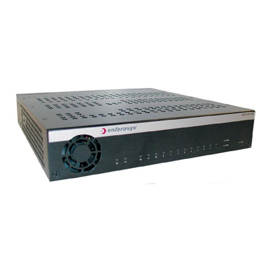
Introduction The Enterasys Networks ® D2 family of switches is designed to handle networking demands in a variety of business and institutional environments. Because the D2 operates with low noise emissions, this feature rich device is as suited to installation in conference rooms, office cubicles, and classrooms as it is to wiring closet installations. The D2 switch is a policy‐capable device powered by external redundant power supplies that support Power over Ethernet (PoE) and other enterprise class features. Overview The D2 product family includes the D2G124‐12 and D2G124‐12P switches, power supply options (redundant as well as additional power), and switch mounting hardware. D2G124-12 and D2G124-12P Switches The D2G124‐12 and D2G124‐12P systems provide twelve copper 10/100/1000 RJ45 ports and two 1‐Gigabit Small Form Factor Pluggable (SFP) fiber‐optic transceiver combo ports. Power over Ethernet (PoE) is factory installed on the D2G124‐12P. A D2 switch can be placed on a table‐top as a freestanding unit, installed into a standard 48.26‐centimeter (19‐inch) rack, mounted on a wall, or mounted under a table. The width of the D2 allows for two switches to be installed side‐by‐side into a standard rack. In addition, a wall‐mounted lockbox is available to secure the unit and cables from tampering after installation is complete. The D2G124‐12 and D2G124‐12P switches are shown in Figure 1‐1 and Figure 1‐2 on page 1‐2. The D2 switch’s status LEDs are visible from the front, rear, and top of the switch. Console and Ethernet ports are located on the rear panel. An add‐on plastic cover can be ordered separately and installed over the switch when used as a freestanding unit or mounted on a wall. Enterasys D-Series Hardware Installation Guide 1-1... -
Page 22: D2G124-12P Switch (Rear View) Without Plastic Cover Installed
Console port (RJ45) Reset button Power Supply 2 (PWR2) LED RJ45 ports (1-12) Figure 1-2 D2G124-12P Switch (top and front view) without plastic cover installed CPU (system) LED Power supply (PWR1 and PWR2) LEDs 1-2 Introduction SFP combo ports (11 and 12) -
Page 23: Features
– Twelve RJ45 (10/100/1000Mbps,1000BASE‐TX copper) ports plus two combo SFP ports in the rear panel Notes: Each combo SFP port on the D2G124-12 and D2G124-12P supports the installation of Mini-GBICs for 1000Base-SX, 1000Base-LX, 100Base-FX or 1000Base-T copper SFP transceivers. Each combo SFP port in use on these units eliminates the availability of one RJ45 port. In other words, only twelve ports can be active at any given time. -
Page 24: D2-Hipwr-Poe Power Combiner
PoE (Power over Ethernet) Support • LEDs LEDs are visible from the top, front, and rear panels of the D2 switch and include: – The CPU LED indicates the state of the system, as described in Table – Two power LEDs (PWR1 and PWR2) indicate voltage for the primary and secondary power inputs as described in Table Port LEDs indicate the operational status of ports in the rear panel, as described in Table page 3‐2. D2-HIPWR-POE Power Combiner The D2‐HIPWR‐POE is an optional power combiner that provides a full 15.4 watts of PoE to all twelve RJ45 ports on the D2G124‐12P. The D2‐HIPWR‐POE combines the power output of two D2‐ PWR‐POE power supplies into a single output that can be plugged into a D2G124‐12P switch. You can connect a single D2‐HIPWR‐POE power combiner to your D2G124‐12P switch, or two D2‐HIPWR‐POE power combiners for redundant PoE on all twelve front panel RJ45 ports. Figure 1‐3 shows the front panel LEDs and rear panel inputs of the D2‐HIPWR‐POE power combiner. Figure 1-3 D2-HIPWR-POE Status LEDs Power Inputs PoE (Power over Ethernet) Support The D2G124‐12P switch is 802.3af compliant. This means the switch is capable of providing up to ... -
Page 25: Powered Device Classifications (Pds)
Power over Ethernet (PoE) refers to the ability to provide 48 Vdc power to a powered device using the same Ethernet cabling that provides data. Modern Ethernet implementations employ differential signals over twisted pair cables. This requires a minimum of two twisted pairs for a single physical link. Both ends of the cable are isolated with transformers blocking any DC or common mode voltage on the signal pair. PoE exploits this fact by using two twisted pairs as the two conductors to supply a direct current. One pair carries the power supply current and the other pair provides a path for the return current. While several proprietary legacy implementations of PoE have been deployed by LAN equipment vendors, in 2003 the IEEE published the IEEE 802.3af specification, which is part of the 802.3 suite of standards. The switch is fully compliant with the IEEE 802.3af standard. It supports the standard resistor‐based detection method, as well as AC disconnect capability. When operating at 40°C or less, the switch supports an average of 8.3W PoE power per port. It provides up to 15.4W for Class 3 support on any port, up to a system maximum of 100 watts. Total system PoE power decreases 2.16W per °C increase over 40°C. Powered Device Classifications (PDs) PDs are devices that receive their operating 48 Vdc power through a new or existing Ethernet cable from a switch or other device that can provide a PoE‐compliant port connection. This enables the PD to operate in a location without local power. For example: • Devices such as PoE‐compliant remote EXIT signs and Personal Data Assistants (PDAs), • Devices that support Voice over IP such as PoE‐compliant digital telephones, • Devices that support Wireless Application Protocol (WAP) such as security cameras, laptop PCs, and many more devices. PoE (Power over Ethernet) Support Enterasys D-Series Hardware Installation Guide 1-5... - Page 26 PoE (Power over Ethernet) Support 1-6 Introduction...
-
Page 27: Installation
Mounting the Switch Connecting Power to the Switch Connecting to the Console Port Connecting to the Network Installing the Optional Plastic Cover Completing the Installation Installation Refer to page... 2-26 2-27 2-28 2-28 2-35 Enterasys D-Series Hardware Installation Guide 2-1... -
Page 28: Unpacking The D2 Switch
Unpacking the D2 Switch Unpacking the D2 Switch Note: Unpack the D2 switch components only as needed. Leave the components in their respective shipping cartons until you are ready to install that component. Save all shipping materials in the event that the switch has to be repacked. -
Page 29: Order Of Installation Steps
“Installing the Switch in the Lockbox and Mounting on a Wall” (page 2‐15) Connect power to the switch. Refer to “Connecting Power to the Switch” on page 2‐26. Connect to the console port. Refer to “Connecting to the Console Port” on page 2‐27. Connect to the network (including installing optional SFPs). Refer to “Connecting to the Network” on page 2‐28. Install the optional plastic cover. Refer to “Installing the Optional Plastic Cover” on page 2‐33. Complete the installation. Refer to “Completing the Installation” on page 2‐35. Using the Switch as a Freestanding Device If you are installing the D2 switch as a freestanding device, choose an appropriate flat, secure location, such as a desk top, and: If desired, install the optional rubber feet underneath the switch by affixing one securely in each of the four corners. (Optional) Connect the D2‐HIPWR‐POE power combiner as described in “Connecting a D2‐ HIPWR‐POE Power Combiner” on page 2‐25. Proceed to connect power to the switch as described in “Connecting Power to the Switch” on page 2‐26. Order of Installation Steps Enterasys D-Series Hardware Installation Guide 2-3... -
Page 30: Mounting The Switch
Caution: Before installing the screws as described in this installation procedure, refer to Values” on page A-3. Precaución: Antes de retirar los tornillos, tal como se describe en las instrucciones de instalación, consulte Installing the Switch into a Rack The D2 switch can be single or dual‐mounted in a standard EIA‐310‐D compliant 48.26‐centimeter (19‐inch) equipment rack. To mount one or two switches into a rack, you must first install each switch into a rack mount kit as described in the following procedure. You must provide the ... -
Page 31: Positioning And Securing One Or Two Switches
Positioning and Securing One or Two Switches Figure 2-4 Installing a Switch in the Rack Mount Kit (D2G124-12P shown) Front edge of switch To install a switch in the rack mount kit, proceed as follows: Mount the switch in the mounting tray by sliding the front edge of the switch underneath the lip on the mounting tray as shown in Figure bottom of the switch with the three holes in the rack mounting tray. (Optional) Repeat Step tray. Rack mounting tray lip 2‐4, and aligning the three screw holes on the 1 to mount a second switch on the opposite side of the rack mounting Enterasys D-Series Hardware Installation Guide 2-5 Mounting the Switch... -
Page 32: Installing One Or More Power Supplies
Mounting the Switch Figure 2-5 Fastening Switch(es) to the Rack Mounting Tray (two D2G124-12Ps shown) Rear edge of switch Using the screws provided (three for each switch), fasten each switch to the rack mounting tray as shown in Figure Installing One or More Power Supplies The D2 rack mount kit provides mounting positions for up to four power supplies (up to two for each mounted switch). Depending on whether you have one or two switches in the rack mount kit, and whether you want one or two power supplies for each switch, the method you use to secure each power supply may vary slightly. Choose one of the following options for installing a power supply in the rack mount kit: • “Edge of Tray Installation” (page 2‐6) • “Middle of Tray Installation” (page 2‐8) Edge of Tray Installation Using one of the hook & loop straps provided, secure a power supply to one of the edge mounting ... -
Page 33: Positioning Of Hook & Loop Straps To Secure Power Supply (Edge Of Tray Shown)
Hook & loop straps DC power cord Outer set of bridge anchors Inner set of bridge anchors 2‐7. AC power cord Outer set of bridge anchors Inner set of bridge anchors Enterasys D-Series Hardware Installation Guide 2-7 Mounting the Switch... - Page 34 Mounting the Switch Plug the power cord from the power supply into the switch DC power receptacle that is appropriate for your type of power supply. • For the D2‐PWR supply, plug into the PWR1‐A or PWR2‐A receptacle. • For the D2‐PWR‐POE supply, plug into the PWR1‐B or PWR2‐B receptacle. Choose one of the following: • If you are done installing power supplies, proceed to “Mounting the Assembled Kit Into a Rack” on page 2‐9. • If you need to install one or more additional power supplies, either ‐ Repeat this Edge of Tray Installation procedure, or ‐ Proceed to the Middle of Tray Installation procedure on page 2‐8. (Optional) Use the wire ties provided to secure the power cords inside the rack mounting tray. Middle of Tray Installation Note: When installing power supplies in the middle of the rack mount tray, you do not need to use the mounting holes on the edge of the tray.
-
Page 35: Mounting The Assembled Kit Into A Rack
D2 switch (Dual D2124-12Ps shown) Connecting Power, Console, and Network Cables Once the assembled rack mount kit is attached to your rack location, proceed to: • Connect power to the switch(es) by plugging each AC power cord into a dedicated, grounded AC outlet. Refer to “Connecting Power to the Switch” on page 2‐26. • Attach console cable(s). Refer to “Connecting to the Console Port” on page 2‐27 for more information. • Attach network cables. Refer to “Connecting to the Network” on page 2‐28 for more information. PWR1-B and PWR2-B PoE DC power receptacles DC power chords Enterasys D-Series Hardware Installation Guide 2-9 Mounting the Switch... -
Page 36: Installing The Switch Under A Table
Caution: The table location and rack mounting screws/anchoring method that the installer selects for mounting the D2 switch must be capable of supporting 60 lbs (27.2kg). Advertencia: La ubicación de la mesa y el método de anclaje o los tornillos de montaje del estante que el instalador seleccione para montar el interruptor D2 deberán ser capaces de soportar un peso... -
Page 37: Attaching The D2-Hipwr-Poe To The Table Mounting Tray
Wrap the ends of the strap over the top of the power supply and fasten securely. Repeat Step 4 to secure the other end of the power supply to the mounting tray. (Optional) Repeat Step 4 to secure a second power supply to the mounting tray. (Optional) If you are installing a D2‐HIPWR‐POE, refer to Figure Figure 2-10 Attaching the D2-HIPWR-POE to the Table Mounting Tray D2-PWR-POE power supply D2G124-12P switch 2‐10 and proceed as follows: Hook & loop fasteners with adhesive D2-HIPWR-POE power combiner Enterasys D-Series Hardware Installation Guide 2-11 Mounting the Switch... -
Page 38: Installing The Switch On A Wall
Plug each AC power cord into a dedicated, grounded AC outlet. See “Connecting Power to the Switch” on page 2‐26 for information on redundancy and the initialization process. Note: Once assembled, the serial number on the bottom of your D2 switch will be visible through the window on the bottom of the table mount kit. Installing the Switch on a Wall Caution: The wall location and wall mounting screws/anchoring method that the installer selects for mounting the D2 switch must be capable of supporting 55 lbs (25kg). -
Page 39: Installing The Switch On A Wall (Shown With One D2-Pwr Supply)
Mount the switch on the front side of the wall mount kit in the direction shown, aligning the three screw holes on the bottom of the unit with the three holes in the wall mount tray. Note: Ensure that the D2 switch is secured to the wall mount tray in the position shown, with the back panel of the switch facing downward. The fan tab on the wall mount tray must face downward when the kit is installed on the wall. -
Page 40: Mounting The D2-Hipwr-Poe To The Wall Mounting Tray
Mounting the Switch Using the hook & loop strap provided, thread the strap through the mounting tray and over the power supply in the following order: Up through the mounting tray bracket at the side of the power supply b. Through the opening in the mounting tray flange Fasten the ends of the hook & loop strap securely around the power supply. Repeat Step Step 6 to secure a second power supply. (Optional) If mounting a D2‐HIPWR‐POE to the wall mounting tray, refer to Figure proceed as follows: Figure 2-12 Mounting the D2-HIPWR-POE to the Wall Mounting Tray ‘‘ Hook & loop fasteners with adhesive With the hook and loop sides attached together, peel back the adhesive covering on one side of each hook & loop fastener and apply to opposite corners on the bottom of the D2‐HIPWR‐POE. b. Once the hook & loop fasteners are adhered to the bottom of the D2‐HIPWR‐POE, remove the adhesive covering on the other side of both hook & loop fasteners and adhere to the table mounting tray. Firmly press the D2‐HIPWR‐POE against the table mounting tray and hold together for a few seconds. 2-14 Installation 5 and ... -
Page 41: Installing The Switch In The Lockbox And Mounting On A Wall
14. (Optional) If you have purchased an optional plastic cover, attach it to the mounted D2 switch as described in “Installing the Optional Plastic Cover” (page 2‐33). Note: Once assembled, the serial number on the bottom of your D2 switch will be accessible through the window on the bottom of the wall mounting tray. In the event you need to view it, you will need to detach the wall mounting tray from the wall and (if installed) remove the power supply from underneath the serial number window. -
Page 42: Installing Power Supplies
Installing the Switch in the D2 Lockbox Tray Mounting screws (three) Mounting screw holes Mount the switch inside the lockbox tray in the direction shown in Figure aligning the three screw holes on the bottom of the unit with the three holes in the lockbox tray. Note: Ensure that the D2 switch is secured to the lockbox tray in the position shown in on page wall. Using the screws provided, fasten the switch to the lockbox tray. Installing Power Supplies Once the switch is secured in the lockbox tray, assemble the rest of the D2 components into the ... -
Page 43: Installing Power Supplies Into The Lockbox Tray
(2) Under the power supply (3) Through the bridge anchor on the other side of the power supply b. Wrap the ends of the strap over the top of the power supply and fasten securely. Repeat step 1 on page 2‐16 with another hook & loop strap to secure the other end of the power supply to the mounting tray. Final placement of power supplies is shown in Figure 2‐14 on page 2‐17. Plug the DC power cord from the power supply into the switch DC power receptacle that is appropriate for your type of power supply. • For the D2‐PWR supply, plug into the PWR1‐A or PWR2‐A receptacle. • For the D2‐PWR‐POE supply, plug into the PWR1‐B or PWR2‐B receptacle. Plug the AC cord into the power supply’s AC receptacle. (Optional) If you have purchased a second power supply and wish to install it, repeat step on page 2‐16 though Step 3 using the second power supply slot in the tray and the unused PWR receptacle appropriate for the supply. Refer to “Connecting Power to the Switch” on page 2‐26 for more information about power redundancy. Plug each AC power cord into a dedicated, grounded AC outlet. See “Connecting Power to the Switch” on page 2‐26 for information about the initialization process. Mounting the Switch Enterasys D-Series Hardware Installation Guide 2-17 1 ... -
Page 44: Installing The D2-Hipwr-Poe In The Lockbox
Mounting the Switch Installing the D2-HIPWR-POE in the Lockbox Note: Enterasys recommends installing the lockbox mounting screws to your wall as described in “Mounting the Lockbox on the Use the following procedure if your D2 lockbox power configuration includes the D2‐HIPWR‐POE power combiner. With the switch secured in the lockbox tray, assemble the rest of the D2 components as follows: Use Figure 2‐15 on page 2‐18 as a guide and thread the hook & loop straps as follows: Through the top‐left upper power supply bridge anchor Through the top‐right upper power supply bridge anchor b. Through the bottom‐left lower power supply bridge anchor Through the bottom‐right lower power supply bridge anchor Figure 2-15 Fastening the Hook &... -
Page 45: Installing The Power Supplies
Figure 2-16 Installing the Power Supplies Seat the lower power supply against the bottom of the lockbox with its DC power cord facing left as shown in Figure 2‐16. Fasten the two hook & loop straps securely around the power supply. Attach the three‐prong end of the connecting cord to the Power1‐B power input on your D2 switch. Thread the DC power cords from both power supplies and the connecting cord in between the D2 switch and the upper power supply and secure them in place with the hook & loop strap, as shown in Figure 2‐17. Figure 2-17 Threading the Cables Mounting the Switch Enterasys D-Series Hardware Installation Guide 2-19... -
Page 46: Seating The D2-Hipwr-Poe In The Lockbox
Mounting the Switch Connect the two, 3‐prong power cords from each power supply to the D2‐HIPWR‐POE’s Power In 1 and 2 power inputs. Attach the connecting cord to the D2‐HIPWR‐POE’s Power Output receptacle. Thread the two power supply AC power cords: – through the hole in the bottom left of the lockbox if not mounting over a power outlet. – in between the D2 switch and upper power supply. Use the hook & loop strap securing the DC power cords and connecting cord to also secure the AC power cords. Plug each AC cord into each power supply’s AC receptacle. Seat the D2‐HIPWR‐POE in the space between the power supplies and the D2 switch as shown in Figure Figure 2-18 Seating the D2-HIPWR-POE in the Lockbox 2-20 Installation 2‐18. -
Page 47: Connecting Network Cabling And Attaching The Wire Relief Bracket
Connecting Network Cabling and Attaching the Wire Relief Bracket The wire relief bracket is designed to hold network cables securely in place and prevent tampering once cabling is connected to switch ports. To attach the wire relief bracket to the lockbox tray: Attach network cables as shown in Figure page 2‐28 for more information. Figure 2-19 Attaching a Network Cable (UTP cable to RJ45 port shown) Align the wire relief bracket with the flange and the two screw holes on the side of the lockbox tray as shown in Figure 2‐19. Refer to “Connecting to the Network” on 2‐20 on page 2‐22. Enterasys D-Series Hardware Installation Guide 2-21 Mounting the Switch... -
Page 48: Mounting The Lockbox On The Wall
Caution: The wall location and wall mounting screws/anchoring method that the installer selects for mounting the D2 lockbox and switch assembly must be capable of supporting 68 lbs (30.84kg). Advertencia: La ubicación de la pared y el método de anclaje o los tornillos de montaje de la pared que el instalador seleccione para montar la caja de seguridad y el conjunto del interruptor D2 deberán ser capaces de soportar un peso de 68 lbs (30.84 kg). -
Page 49: Attaching And Locking The Cover
Position the lockbox screw holes over the installed wall screws. Secure the assembled lockbox in place by pulling slightly downward on the unit. Attaching and Locking the Cover Once the switch and power supplies are assembled in the lockbox tray, and power and network cabling is connected, refer to Figure follows: Network wire relief bracket (shown installed) AC power/data outlet opening Power supply hook & loop strap Fiber adapter opening 2‐22 on page 2‐24 and proceed to attach and lock the cover as Enterasys D-Series Hardware Installation Guide 2-23 Mounting the Switch... -
Page 50: Attaching The D2 Lockbox Cover
Mounting the Switch Figure 2-22 Attaching the D2 Lockbox Cover Cover locking tabs Latch and lock assembly (locking position) Secure the cover over the top of the lockbox assembly by locking the mounting tabs over the lip in the side of the mounting tray. Slide the latch on the lock assembly to the position shown until it clicks into place. Lock the lockbox by turning the provided key in the lock counter‐clockwise. Insert the three cover screws (provided) in the positions shown and tighten securely. Return the lockbox key to a secure location. 2-24 Installation Cover fastening screws (three) -
Page 51: Removing The Lockbox Cover
D2-HIPWR-POE Power Combiner AC Power Cords To connect a D2‐HIPWR‐POE to the D2G124‐12P switch: Connect the DC power cord from each D2‐PWR‐POE power supply to each of the Power In receptacles on the D2‐HIPWR‐POE. Note: The D2-HIPWR-POE will not supply power to the D2 switch until both input power supplies are connected to the D2-HIPWR-POE. 2‐23 as a reference for the following procedure. D2-PWR-POE Power Supplies Connecting Cord Enterasys D-Series Hardware Installation Guide 2-25... -
Page 52: Connecting Power To The Switch
Notes: Both power supplies must be of the same type to support redundancy. The D2-PWR supply will power either the D2G124-12 or the D2G124-12P without PoE support. The D2-PWR-POE is the only supply for powering the D2G124-12P with PoE support To connect power to the D2 switch: ... -
Page 53: Power Led Displays
Unused Unused Unused Unused To connect to the console port: Connect the RJ45 connector at one end of the cable to the RJ45 console port on the D2 switch. Plug the RJ45 connector at the other end of the cable into the RJ45 to DB9 adapter. Connect the RJ45 to DB9 adapter to the serial port on a terminal or a PC running terminal emulation software. Make sure the terminal emulation software is set as follows: – Select the appropriate serial port (COM port 1 or 2). – Set the data rate to 9600 baud. – Set the data format to 8 data bits, 1 stop bit, and no parity. – Set flow control to none. – Set the emulation mode to VT100. – When using HyperTerminal, select Terminal keys, not Windows keys. Status Power supply not present. Normal operation. Enterasys D-Series Hardware Installation Guide 2-27 Connecting to the Console Port... -
Page 54: Connecting To The Network
Connecting to the Network When you are ready to begin configuring the D2 switch, use the procedures in “Completing the Installation” on page 2‐35 to power on the switch and boot the software. You will perform initial setup by entering CLI commands on the management console. Table 2-3 RJ45 to DB9 Adapter Pinout Signal Receive (RX) Transmit (TX) Ground (GRD) For a description of how to use the CLI and descriptions of all the CLI commands, refer to the Enterasys D‐Series CLI Reference. Connecting to the Network The following procedures cover the cable connections from the network or other devices to the D2 switch. • Connecting UTP Cables to RJ45 Ports • Installing an Optional SFP on page 2‐29 • Connecting Fiber‐Optic Cables to SFP Ports on page 2‐32 Connecting UTP Cables to RJ45 Ports RJ45 10000BASE‐TX front panel ports on the D2G124‐12 and D2G124‐12P switches support Auto ... -
Page 55: Installing An Optional Sfp
Repeat all steps above until all connections have been made. Installing an Optional SFP Notes: Each combo SFP port on the D2G124-12 and D2G124-12P supports the installation of Mini- GBICs for 1000Base-SX, 1000Base-LX, or 100Base-FX SFP transceivers. Each combo SFP port in use on these units eliminates the availability of one RJ45 port. In other words, only twelve ports can be active at any given time on components equipped with a combination of RJ45 and SFP interfaces. - Page 56 Connecting to the Network Warning: Fiber-optic SFPs use Class 1 lasers. Do not use optical instruments to view the laser output. The use of optical instruments to view laser output increases eye hazard. When viewing the output optical port, power must be removed from the network adapter. Advertencia: Los SFPs de fibra optica usan lasers de clase 1.
-
Page 57: Removing An Sfp
Mientras no esté instalado, mantenga el SFPen su bolsa antiestática o en cualquier otro recipiente antiestático. To remove a transceiver from a With an antistatic wrist strap attached to your wrist, remove the cables connected to the transceiver. Release the transceiver using its wire handle (located under the front end of the transceiver.) Specific operation of the handle will vary depending on transceiver type. Grasp the sides of the transceiver and pull it straight out of the port slot. Edge connector (insertion side) Port slot Transceiver side view port slot, refer back to Figure 2‐25 and proceed as follows: Enterasys D-Series Hardware Installation Guide 2-31 Connecting to the Network... -
Page 58: Connecting Fiber-Optic Cables To Sfp Ports
Connecting to the Network If storing or shipping an SFP which has a fiber‐optic connector, insert its protective dust cover to protect the ends of the fiber‐optic fibers from dust or contamination. Connecting Fiber-Optic Cables to SFP Ports Before connecting cables to SFP ports, you must install the appropriate transceiver as described in Installing an Optional SFP on page 2‐29. This section describes how to connect a 1‐Gigabit fiber‐ optic segment from the network or other devices to an MT‐RJ or LC port connector. Each fiber‐optic link consists of two fiber‐optic strands within the cable for Transmit (TX) and Receive (RX). The transmit strand from a device port connects to the receive port of a fiber‐optic 1‐Gigabit Ethernet device at the other end of the segment. The receive strand of the applicable LC or MT‐RJ port connects to the transmit port of the fiber‐optic 1‐Gigabit Ethernet device. Caution: Do not touch the ends of the fiber-optic strands, and do not let the ends come in contact with dust, dirt, or other contaminants. Contamination of cable ends causes problems in data transmissions. -
Page 59: Installing The Optional Plastic Cover
Note: The optional plastic cover can be installed over a freestanding unit or a unit mounted in a D2-WALL-MNT kit. It is not intended for use in a D2 lockbox. Installing the Optional Plastic Cover 2 LC cable connector Release tab 2‐27 on page 2‐34. Enterasys D-Series Hardware Installation Guide 2-33... -
Page 60: Installing The Optional Plastic Cover (Freestanding Switch Shown)
Installing the Optional Plastic Cover Figure 2-27 Installing the Optional Plastic Cover (freestanding switch shown) Cover mounting screws (four) Cover mounting screw holes (four) To install the plastic cover: Align the fan and LED openings on the front panel of the plastic cover over the front panel of the switch. • If the switch is freestanding, front panel LEDs will align as shown in Figure open end of the cover will align with the rear panel of the switch, allowing access to the ports and network, power and console cables. • If the switch is mounted on the wall as shown in Figure LEDs will face up (towards the ceiling), and the open end of the cover will face down (away from the ceiling), allowing access to the ports and network, power and console cables. Secure the cover in place. When positioned securely, mounting tabs inside the edge of the cover will snap into place into corresponding notches on the switch. 2-34 Installation... -
Page 61: Completing The Installation
Completing the Installation Power on the switch. Note: The D2 fans turn on when power is first supplied to the switch and will shut off automatically. The fans will turn back on automatically if the temperature ever exceeds the following ambient thresholds: •... - Page 62 Note: It is strongly recommended that you change the admin password from its default state of blank (no password), once the D2 switch becomes operational in your network. For more information, refer to the Enterasys D-Series CLI Reference If you require assistance, contact Enterasys Networks using one of the methods described in ...
-
Page 63: Chapter 3: Troubleshooting
Status No power. Major system failure, including failure to boot. Power on self-test failed. Diagnostics are running. Functional image is loaded. System is booting. System is fully operational. Enterasys D-Series Hardware Installation Guide 3-1 Troubleshooting Refer to page... 3‐1. 1‐1 ... -
Page 64: Power Leds
Note: Notify the system administrator before changing the password. To reset the D2 switch password: Locate the reset button on the back of the switch as shown in Figure Press‐and‐hold the reset button while the switch is operational. This changes the login password to the default password and will be indicated by means of the command line interface (CLI) only. You can now logon to the switch through the console port using the default password, and assign a new password using the CLI. To access switch management from your local PC, terminal, or modem connection, refer to the Enterasys D‐Series CLI Reference for instructions on how to log in and enter a new password. If you require assistance, contact Enterasys Networks using one of the methods described in “Getting Help” on page xvii. 3-2 Troubleshooting 3‐2 describes their status. Status Power supply not present. Normal operation. Status No link established. Ethernet link established without activity. For combo SFP ports, this indicates power up. -
Page 65: Resetting The D2-Hipwr-Poe
Resetting the D2-HIPWR-POE The D2‐HIPWR‐POE will shut down in the event of an overload or short circuit. To reset the D2‐HIPWR‐POE: • Disconnect AC power to one of the power supplies. Wait 30 seconds (to allow the DC output voltage to decay enough to reset the D2‐HIPWR‐POE) before re‐applying AC power. • Remove and replace one of the D2‐HIPWR‐POE’s power input cables, no minimum time required. Resetting the D2-HIPWR-POE Enterasys D-Series Hardware Installation Guide 3-3... - Page 66 Resetting the D2-HIPWR-POE 3-4 Troubleshooting...
-
Page 67: A-1 D2 Specifications
When an SFP transceiver (Mini-GBIC) in SFP port 11 establishes a link, RJ45 port 11 is disabled. When an SFP transceiver in SFP port 12 establishes a link, RJ45 port 12 is disabled. MPC8241, 266 MHz processor 256 MB 32 MB Enterasys D-Series Hardware Installation Guide A-1 Specifications Refer to page... -
Page 68: D2-Hipwr-Poe Specifications
50-60Hz • D2G124-12 - 2.0A • D2G124-12P - 3.2A • D2G124-12 - 110V - 0.3A / 102.39 (BTUs/hr) • D2G124-12P - 110V - 2.16A / 443.69 (BTUs/hr) • D2G124-12 - 0°C to 60°C (32°F to 140°F) • D2G124-12P - 0°C to 50°C (32°F to 122°F) -40°C to 70°C (-40°F to 158°F) -
Page 69: Power Supply Specifications
100 - 240Vac / 3.2A 50V 2.6 A max Torque in Pounds Metric Nominal 1.42 2.85 4.75 8.55 17.10 18.0 30.40 32.0 63.65 67.0 Enterasys D-Series Hardware Installation Guide A-3 Power Supply Specifications Bit Size 1.57 3.15 5.25 9.45 18.90 33.60 70.35... -
Page 70: 1-Gigabit Ethernet And 100Base-Fx Transceiver (Sfp) Specifications
1-Gigabit Ethernet and 100Base-FX Transceiver (SFP) Specifications 1-Gigabit Ethernet and 100Base-FX Transceiver (SFP) Specifications The D2 SFP (Mini‐GBIC) port interface slots support 1‐Gbps fiber‐optic and copper connections as described in Table Table A-5 Mini-GBIC Input/Output Port Specifications Item MGBIC-LC01 MGBIC-MT01 MGBIC-02 MGBIC-LC03 MGBIC-LC04 MGBIC-LC05 MGBIC-LC07 MGBIC-08 MGBIC-LC09 The specifications for the Mini‐GBICs shown in Table A‐6 through Table IEEE 802.3z‐1998 standard. MGBIC-LC01/MGBIC-MT01 Specifications (1000BASE-SX) Table A-6 MGBIC-LC01/MGBIC-MT01 Optical Specifications Item Transmit Power (minimum) Receive Sensitivity... -
Page 71: Mgbic-02 Specifications (1000Base-T
62.5 µm MMF 50 µm MMF -20 dBm -23.5 dBm -31 dBm -31 dBm 11 dBm 7.5 dBm Enterasys D-Series Hardware Installation Guide A-5 50/125 µm MMF -9.5 dBm -3 dBm -20 dBm 10.5 dB Range 2,000 Meters 2,000 Meters... -
Page 72: Mgbic-Lc05 Specifications (100Base-Fx
1-Gigabit Ethernet and 100Base-FX Transceiver (SFP) Specifications MGBIC-LC05 Specifications (100BASE-FX) Table A-12 MGBIC-LC05 Optical Specifications Item Transmit Power (minimum) Receive Sensitivity Link Power Budget MGBIC-LC07 Specifications (1000BASE-ELX) Table A-13 MGBIC-LC07 Optical Specifications Item Transmit Power (minimum) Receive Sensitivity Maximum Input Power Link Power Budget (Full Duplex Only) 1. -
Page 73: Mgbic-Lc09 Specifications (1000Base-Lx
CISPR-22 (Class A). VCCI V-3. CNS 13438 (BSMI), 2004/108/EC (EMC Directive) 2002/95/EC (RoHS Directive), 2002/96/EC (WEEE Directive), Ministry of Information Order #39 (China RoHS) Enterasys D-Series Hardware Installation Guide A-7 Console Port Pinout Assignments 10 µm SMF -9.5 dBm -20 dBm 10.5 dBm... - Page 74 Regulatory Compliance A-8 Specifications...
-
Page 75: Index
Network, connecting to the 2-28 Password reset button Pinout assignments console port Plastic cover installation 2-33 PoE (Power over Ethernet) support Power connecting to the switch 2-26 LED displays 2-27 supply specifications Rack mounting Regulatory compliance SFP port connections 2-32 SFP/XFP installation... - Page 76 Index-2...
Need help?
Do you have a question about the D2G124-12 and is the answer not in the manual?
Questions and answers