Enterasys G3G124-24 Hardware Installation Manual
G-series
Hide thumbs
Also See for G3G124-24:
- Hardware installation manual (59 pages) ,
- Quick reference (2 pages)

Related Manuals for Enterasys G3G124-24


Summary of Contents for Enterasys G3G124-24
- Page 1 ® Enterasys G-Series Ethernet Switch Hardware Installation Guide G3G124-24 G3G124P-24 G3G170-24 9034357-05...
- Page 3 Elektrischer Gefahrenhinweis: Installationen sollten nur durch ausgebildetes und qualifiziertes Personal vorgenommen werden. Notice Enterasys Networks reserves the right to make changes in specifications and other information contained in this document and its web site without prior notice. The reader should in all cases consult Enterasys Networks to determine whether any such changes have been made. The hardware, firmware, or software described in this document is subject to change without notice. IN NO EVENT SHALL ENTERASYS NETWORKS BE LIABLE FOR ANY INCIDENTAL, INDIRECT, SPECIAL, OR CONSEQUENTIAL DAMAGES WHATSOEVER (INCLUDING BUT NOT LIMITED TO LOST PROFITS) ARISING OUT OF OR RELATED TO THIS DOCUMENT, WEB SITE, OR THE INFORMATION CONTAINED IN THEM, EVEN IF ENTERASYS NETWORKS HAS BEEN ADVISED OF, KNEW OF, OR SHOULD HAVE KNOWN OF, THE POSSIBILITY OF SUCH DAMAGES. Enterasys Networks, Inc. 50 Minuteman Road Andover, MA 01810 © 2008 Enterasys Networks, Inc. All rights reserved. Part Number: 9034357‐05 October 2008 ENTERASYS, ENTERASYS NETWORKS, ENTERASYS SECURE NETWORKS, NETSIGHT, ENTERASYS NETSIGHT, and any logos associated therewith, are trademarks or registered trademarks of Enterasys Networks, Inc., in the United States and/or other countries. For a complete list of Enterasys trademarks, see http://www.enterasys.com/company/trademarks.aspx. All other product names mentioned in this manual may be trademarks or registered trademarks of their respective companies. Documentation URL: http://www.enterasys.com/support/manuals Documentacion URL: http://www.enterasys.com/support/manuals Dokumentation im Internet: http://www.enterasys.com/support/manuals...
-
Page 4: Regulatory Compliance Information
Regulatory Compliance Information Federal Communications Commission (FCC) Notice This device complies with Part 15 of the FCC rules. Operation is subject to the following two conditions: (1) this device may not cause harmful interference, and (2) this device must accept any interference received, including interference that may cause undesired operation. NOTE: This equipment has been tested and found to comply with the limits for a class A digital device, pursuant to Part 15 of the FCC rules. These limits are designed to provide reasonable protection against harmful interference when the equipment is operated in a commercial environment. This equipment uses, generates, and can radiate radio frequency energy and if not installed in accordance with the operator’s manual, may cause harmful interference to radio communications. Operation of this equipment in a residential area is likely to cause interference in which case the user will be required to correct the interference at his own expense. WARNING: Changes or modifications made to this device which are not expressly approved by the party responsible for compliance could void the user’s authority to operate the equipment. Industry Canada Notice This digital apparatus does not exceed the class A limits for radio noise emissions from digital apparatus set out in the Radio Interference Regulations of the Canadian Department of Communications. Le présent appareil numérique n’émet pas de bruits radioélectriques dépassant les limites applicables aux appareils numériques de la class A prescrites dans le Règlement sur le brouillage radioélectrique édicté par le ministère des Communications du Canada. Class A ITE Notice WARNING: This is a Class A product. In a domestic environment this product may cause radio interference in which case the user may be required to take adequate measures. Clase A. Aviso de ITE ADVERTENCIA: Este es un producto de Clase A. En un ambiente doméstico este producto puede causar interferencia de radio ... - Page 5 BSMI EMC Statement — Taiwan This is a class A product. In a domestic environment this product may cause radio interference in which case the user may be required to take adequate measures. AS/NZS CISPR 22 Hazardous Substances This product complies with the requirements of European Directive, 2002/95/EC, Restriction of Hazardous Substances (RoHS) in Electrical and Electronic Equipment. European Waste Electrical and Electronic Equipment (WEEE) Notice In accordance with Directive 2002/96/EC of the European Parliament on waste electrical and electronic equipment (WEEE): The symbol above indicates that separate collection of electrical and electronic equipment is required and that this product was placed on the European market after August 13, 2005, the date of enforcement for Directive 2002/96/EC. When this product has reached the end of its serviceable life, it cannot be disposed of as unsorted municipal waste. It must be collected and treated separately. It has been determined by the European Parliament that there are potential negative effects on the environment and human health as a result of the presence of hazardous substances in electrical and electronic equipment. It is the users’ responsibility to utilize the available collection system to ensure WEEE is properly treated. For information about the available collection system, please go to www.enterasys.com/services/support/ or contact Enterasys Customer Support at 353 61 705586 (Ireland).
- Page 6 Supplement to Product Instructions (Hazardous Substance) (Parts) (Metal Parts) Circuit Modules) Cables & Cable Assemblies) (Plastic and Polymeric parts) Circuit Breakers) SJ/T 11363-2006 Indicates that the concentration of the hazardous substance in all homogeneous materials in the parts is below the relevant threshold of the SJ/T 11363-2006 standard. SJ/T 11363-2006 Indicates that the concentration of the hazardous substance of at least one of all homogeneous materials in the parts is above the relevant threshold of the SJ/T 11363-2006 standard.
-
Page 7: Safety Information
Safety Information Class 1 Laser Transceivers The single mode interface modules use Class 1 laser transceivers. Read the following safety information before installing or operating these modules. The Class 1 laser transceivers use an optical feedback loop to maintain Class 1 operation limits. This control loop eliminates the need for maintenance checks or adjustments. The output is factory set, and does not allow any user adjustment. Class 1 Laser transceivers comply with the following safety standards: • 21 CFR 1040.10 and 1040.11 U.S. Department of Health and Human Services (FDA). • IEC Publication 825 (International Electrotechnical Commission). • CENELEC EN 60825 (European Committee for Electrotechnical Standardization). When operating within their performance limitations, laser transceiver output meets the Class 1 accessible emission limit of all three standards. Class 1 levels of laser radiation are not considered hazardous. When the connector is in place, all laser radiation remains within the fiber. The maximum amount of radiant power exiting the ‐6 fiber (under normal conditions) is ‐12.6 dBm or 55 x 10 watts. -
Page 8: Declaration Of Conformity
Declaration of Conformity Application of Council Directive(s): 2004/108/EC 2006/95/EC Manufacturer’s Name: Enterasys Networks, Inc. Manufacturer’s Address: 50 Minuteman Road Andover, MA 01810 European Representative Name: Enterasys Networks, Ltd. European Representative Address: Nexus House, Newbury Business Park London Road, Newbury Berkshire RG14 2PZ, England Conformance to Directive(s)/Product Standards: EC Directive 2004/108/EC EN 55022:2006 EN 55024:1998 EN 61000‐3‐2:2000 EN 61000‐3‐3:1995 EC Directive 2006/95/EC EN 60950‐1:2001 EN 60825‐1:1994 EN 60825‐2:2004 Equipment Type/Environment: Information Technology Equipment, for use in a Commercial or Light Industrial Environment. Enterasys Networks, Inc. declares that the equipment packaged with this notice conforms to the above directives. - Page 9 NTERASYS ETWORKS IRMWARE ICENSE GREEMENT BEFORE OPENING OR UTILIZING THE ENCLOSED PRODUCT, CAREFULLY READ THIS LICENSE AGREEMENT. This document is an agreement (“Agreement”) between the end user (“You”) and Enterasys Networks, Inc., on behalf of itself and its Affiliates (as hereinafter defined) (“Enterasys”) that sets forth Your rights and obligations with respect to the Enterasys software program/firmware (including any accompanying documentation, hardware or media) (“Program”) in the package and prevails over any additional, conflicting or inconsistent terms and conditions appearing on any purchase order or other document submitted by You. “Affiliate” means any person, partnership, corporation, limited liability company, other form of enterprise that directly or indirectly through one or more intermediaries, controls, or is controlled by, or is under common control with the party specified. This Agreement constitutes the entire understanding between the parties, with respect to the subject matter of this Agreement. The Program may be contained in firmware, chips or other media. BY INSTALLING OR OTHERWISE USING THE PROGRAM, YOU REPRESENT THAT YOU ARE AUTHORIZED TO ACCEPT THESE TERMS ON BEHALF OF THE END USER (IF THE END USER IS AN ENTITY ON WHOSE BEHALF YOU ARE AUTHORIZED TO ACT, “YOU” AND “YOUR” SHALL BE DEEMED TO REFER TO SUCH ENTITY) AND THAT YOU AGREE THAT YOU ARE BOUND BY THE TERMS OF THIS AGREEMENT, WHICH INCLUDES, AMONG OTHER PROVISIONS, THE LICENSE, THE DISCLAIMER OF WARRANTY AND THE LIMITATION OF LIABILITY. IF YOU DO NOT AGREE TO THE TERMS OF THIS AGREEMENT OR ARE NOT AUTHORIZED TO ENTER INTO THIS AGREEMENT, ENTERASYS IS UNWILLING TO LICENSE THE PROGRAM TO YOU AND YOU AGREE TO RETURN THE UNOPENED PRODUCT TO ENTERASYS OR YOUR DEALER, IF ANY, WITHIN TEN (10) DAYS FOLLOWING THE DATE OF RECEIPT FOR A FULL REFUND. IF YOU HAVE ANY QUESTIONS ABOUT THIS AGREEMENT, CONTACT ENTERASYS NETWORKS, LEGAL DEPARTMENT AT (978) 684‐1000. You and Enterasys agree as follows: LICENSE. You have the non‐exclusive and non‐transferable right to use only the one (1) copy of the Program provided in this package subject to the terms and conditions of this Agreement. RESTRICTIONS.
- Page 10 Vietnam, or such other countries as may be designated by the United States Government), (ii) export to Country Groups D:1 or E:2 (as defined herein) the direct product of the Program or the technology, if such foreign produced direct product is subject to national security controls as identified on the U.S. Commerce Control List, or (iii) if the direct product of the technology is a complete plant or any major component of a plant, export to Country Groups D:1 or E:2 the direct product of the plant or a major component thereof, if such foreign produced direct product is subject to national security controls as identified on the U.S. Commerce Control List or is subject to State Department controls under the U.S. Munitions List. UNITED STATES GOVERNMENT RESTRICTED RIGHTS. The enclosed Program (i) was developed solely at private expense; (ii) contains “restricted computer software” submitted with restricted rights in accordance with section 52.227‐19 (a) through (d) of the Commercial Computer Software‐Restricted Rights Clause and its successors, and (iii) in all respects is proprietary data belonging to Enterasys and/or its suppliers. For Department of Defense units, the Program is considered commercial computer software in accordance with DFARS section 227.7202‐3 and its successors, and use, duplication, or disclosure by the U.S. Government is subject to restrictions set forth herein. DISCLAIMER OF WARRANTY. EXCEPT FOR THOSE WARRANTIES EXPRESSLY PROVIDED TO YOU IN WRITING BY ENTERASYS, ENTERASYS DISCLAIMS ALL WARRANTIES, EITHER EXPRESS OR IMPLIED, INCLUDING BUT NOT LIMITED TO IMPLIED WARRANTIES OF MERCHANTABILITY, SATISFACTORY QUALITY, FITNESS FOR A PARTICULAR PURPOSE, TITLE AND NON‐INFRINGEMENT WITH RESPECT TO THE PROGRAM. IF IMPLIED WARRANTIES MAY NOT BE DISCLAIMED BY APPLICABLE LAW, THEN ANY IMPLIED WARRANTIES ARE LIMITED IN DURATION TO THIRTY (30) DAYS AFTER DELIVERY OF THE PROGRAM TO YOU. LIMITATION OF LIABILITY. IN NO EVENT SHALL ENTERASYS OR ITS SUPPLIERS BE LIABLE FOR ANY DAMAGES WHATSOEVER (INCLUDING, WITHOUT LIMITATION, DAMAGES FOR LOSS OF BUSINESS, PROFITS, BUSINESS INTERRUPTION, LOSS OF BUSINESS INFORMATION, SPECIAL, INCIDENTAL, CONSEQUENTIAL, OR RELIANCE DAMAGES, OR OTHER LOSS) ARISING OUT OF THE USE OR INABILITY TO USE THE PROGRAM, EVEN IF ENTERASYS HAS BEEN ADVISED OF THE POSSIBILITY OF SUCH DAMAGES. THIS FOREGOING LIMITATION SHALL APPLY REGARDLESS OF THE CAUSE OF ACTION UNDER WHICH DAMAGES ARE SOUGHT. THE CUMULATIVE LIABILITY OF ENTERASYS TO YOU FOR ALL CLAIMS RELATING TO THE PROGRAM, IN CONTRACT, TORT OR OTHERWISE, SHALL NOT EXCEED THE TOTAL AMOUNT OF FEES PAID TO ENTERASYS BY YOU FOR THE RIGHTS GRANTED HEREIN. AUDIT RIGHTS. You hereby acknowledge that the intellectual property rights associated with the Program are of critical value to Enterasys, and, accordingly, You hereby agree to maintain complete books, records and accounts showing (i) license fees due and paid, and (ii) the use, copying and deployment of the Program. You also grant to Enterasys and its authorized representatives, upon reasonable notice, the right to audit and examine during Your normal business hours, Your books, records, accounts and hardware devices upon which the Program may be deployed to verify compliance with this Agreement, including the verification of the license fees due and paid Enterasys and the use, copying and deployment of the Program. Enterasys’ right of examination shall be exercised reasonably, in good faith and in a manner calculated to not unreasonably interfere with Your business. In the event such audit discovers non‐compliance with this Agreement, including copies of the Program made, used or deployed in breach of this Agreement, You shall promptly pay to Enterasys the appropriate license fees. Enterasys reserves the right, to be exercised in its sole discretion and without prior notice, to terminate this license, effective immediately, for failure ...
- Page 11 13. SEVERABILITY. In the event any provision of this Agreement is found to be invalid, illegal or unenforceable, the validity, legality and enforceability of any of the remaining provisions shall not in any way be affected or impaired thereby, and that provision shall be reformed, construed and enforced to the maximum extent permissible. Any such invalidity, illegality, or unenforceability in any jurisdiction shall not invalidate or render illegal or unenforceable such provision in any other jurisdiction. 14. TERMINATION. Enterasys may terminate this Agreement immediately upon Your breach of any of the terms and conditions of this Agreement. Upon any such termination, You shall immediately cease all use of the Program and shall return to Enterasys the Program and all copies of the Program.
-
Page 13: Table Of Contents
Removing an XFP/SFP .......................... 2-21 Connecting Fiber-Optic Cables to SFP/XFP Ports ................. 2-21 Completing the Installation ........................... 2-22 Installing an Optional PoE Module in the G3G124-24 Switch ..............2-23 Removing the Switch Cover ........................2-23 Installing the PoE Module ........................2-24... - Page 14 Index Figures G3G124-24 Switch (front view) with one G3G-24TX IOM installed in Slot 2........1-1 G3G124-24 Switch (rear view) with 1200 and 400-watt power supplies installed ......1-2 Attaching the Brackets to the Switch (G3G124-24 with G3G-24TX IOM shown) ....... 2-5 Installing a Power Supply Module (1200-watt module into PWR 2 slot shown) ........
- Page 15 Tables Power Distribution According to Number of Installed Power Supplies ..........2-6 Console Port Pinout.......................... 2-15 RJ45 to DB9 Adapter Pinout ......................2-15 SYSTEM LED Definitions ........................3-2 Power LED Definitions........................3-3 IOM Status LED Definitions ........................ 3-3 Port LED Definitions ........................... 3-3 G3 Switch Specifications ........................A-1 Power Supply Specifications ......................A-3 G3G-24TX IOM Specifications ......................A-3...
-
Page 17: About This Guide
About This Guide ® This guide provides an overview, specifications and instructions for installing the Enterasys G‐Series Ethernet Switch in a standard 19‐inch equipment rack or on a suitable flat surface. This guide also explains how to interpret the system status LEDs to facilitate troubleshooting when necessary, and also provides information on how to contact Enterasys Networks for additional help. Who Should Use This Guide Electrical Hazard: Only qualified personnel should install or service this unit. Riesgo Electrico: Nada mas personal capacitado debe de instalar o darle servicio a esta unida. Elektrischer Gefahrenhinweis: Installationen oder Servicearbeiten sollten nur durch ausgebildetes und qualifiziertes Personal vorgenommen werden. -
Page 18: Document Conventions
Document Conventions Document Conventions The following typographical conventions and icons are used in this guide. blue type Indicates a hypertext link. When reading this document online, click the text in blue to go to the referenced figure, table, or section. Lowercase x Indicates the general use of an alphanumeric character (for example, 6x1xx, the x’s indicate a combination of numbers or letters). -
Page 19: Getting Help
World Wide Web www.enterasys.com/services/support/ Phone 1-800-872-8440 (toll-free in U.S. and Canada) or 1-978-684-1000 To find the Enterasys Networks Support toll-free number in your country: www.enterasys.com/services/support/contact Internet mail support@enterasys.com To expedite your message, please type [Switching] in the subject line. To send comments or suggestions concerning this document to the Technical Publications Department: techpubs@enterasys.com... - Page 20 Getting Help xviii About This Guide...
-
Page 21: Chapter 1: Introduction
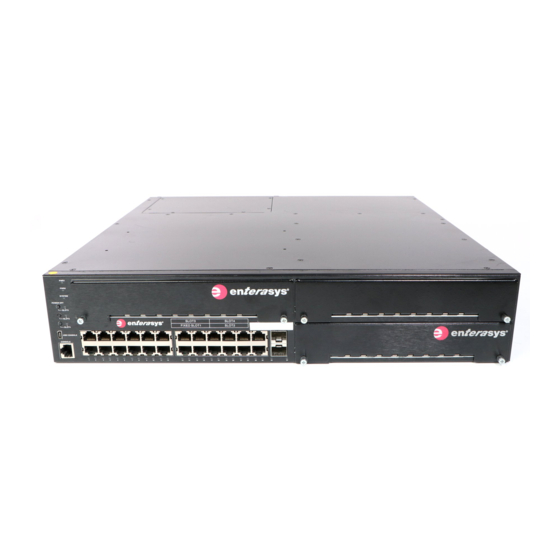
The G‐Series switch can be placed as a freestanding unit or installed into a standard 48.26‐ centimeter (19‐inch) rack. Figure 1-1 G3G124-24 Switch (front view) with one G3G-24TX IOM installed in Slot 2. SYSTEM LED SFP combo ports Power Supply LEDs (PWR1 and PWR2) IOM handle (G3G-24TX in Slot 2) IOM power off buttons (Slots 2, 3 and 4) -
Page 22: Features
G3K‐2XFP, a 2‐port XFP module – G3K‐4XFP, a 4‐port XFP module Notes: Each combo SFP port on the G3G124-24, G3G124-24P or G3G-24TX supports the installation of Mini-GBICs for 1000Base-SX, 1000Base-LX, 100Base-FX or 1000Base-T copper SFP transceivers. Each combo SFP port in use on these 10/100/1000 base systems or the G3G-24TX module eliminates the availability of one RJ45 port. - Page 23 Features • Standalone or Rack Mountable Chassis The G‐Series Ethernet switch can be installed as a freestanding unit on a shelf or table. Optionally, it can be mounted into a standard 48.26‐centimeter (19‐inch) equipment rack. • Optional PoE – PoE is factory installed on the G3G124‐24P base system. – G3G‐POE, a module that enables PoE for 24 ports is available for any installed G3G‐24TX IOM or the G3G124‐24 base system. Refer to “PoE (Power over Ethernet) Support” on page 1‐4 for more information. • Power Supplies The G‐Series switch requires 100~240 VAC input and has two power supply slots located in the rear of the base unit. Power supplies must be ordered separately since they are not provided with the base switch. The following power supplies are available for purchase from Enterasys: – G3‐PWR, a 400‐watt AC power supply capable of providing power to a fully‐loaded non‐ PoE switch and some PoE power (requires 15 Amp circuit) – G3‐PWR‐POE, a 1200‐watt AC power supply recommended for full PoE capability (requires 20 Amp circuit) The power supplies are removable. They can be mixed and can be used redundantly with full load sharing, or non‐redundantly. The switch is capable of supporting 48 PoE ports at 15.4 watts fully redundant, and 96 PoE ports at 15.4 watts in non‐redundant mode. For more information about power supplies, refer to “Power Supply Installation Considerations” on page 2‐5. • Power LEDs The two power LEDs indicate voltage for the primary and secondary power inputs. • Fans The G‐Series switch has nine fans in two different sizes located in three zones to serve different cooling functions. It supports fan redundancy, which means that the system will remain operational if one fan fails. Refer to “Fan Management” on page 1‐4 for more information.
-
Page 24: Poe (Power Over Ethernet) Support
Features PoE (Power over Ethernet) Support The G3G124‐24P switch is 802.3af compliant out‐of‐box. The G3G124‐24 and the G3G‐24TX IOM can be equipped with user‐installed optional PoE modules to make them 802.3af compliant. For more information about installing optional PoE modules, see “Installing an Optional PoE Module on the G3G‐24TX IOM” on page 2‐10 and “Installing an Optional PoE Module in the G3G124‐24 Switch” on page 2‐23. The G3G switches and IOMs that are 802.3af compliant provide Power over Ethernet cable connections from their RJ45 front panel connectors to powered devices (PDs) in the network. Power over Ethernet (PoE) refers to the ability to provide 48 Vdc power to a powered device using the same Ethernet cabling that provides data. Modern Ethernet implementations employ differential signals over twisted pair cables. This requires a minimum of two twisted pairs for a single physical link. Both ends of the cable are isolated with transformers blocking any DC or common mode voltage on the signal pair. PoE exploits this fact by using two twisted pairs as the two conductors to supply a direct current. One pair carries the power supply current and the other pair provides a path for the return current. While several proprietary legacy implementations of PoE have been deployed by LAN equipment vendors, in 2003 the IEEE published the IEEE 802.3af specification, which is part of the 802.3 suite of standards. The switch is fully compliant with the IEEE 802.3af standard. It supports the standard resistor‐ based detection method, as well as AC disconnect capability. The switch is also capable of supplying 15.4 watts of power to 96 ports in nonredundant power mode, and 9.4 watts of power to 96 ports in redundant power mode. Powered Device Classifications (PDs) PDs are devices that receive their operating 48 Vdc power through a new or existing Ethernet cable from a switch or other device that can provide a PoE‐compliant port connection. This enables the PD to operate in a location without local power. For example: • Devices such as PoE‐compliant remote EXIT signs and Personal Data Assistants (PDAs), • Devices that support Voice over IP such as PoE‐compliant digital telephones, • Devices that support Wireless Application Protocol (WAP) such as security cameras, laptop ... - Page 25 Features For fan group 1, when all appropriate temperature sensors register temperatures of 50 degrees C or lower, group 1 fans run at 60% of maximum speed. If firmware detects any sensor reading (on the baseboard or any IOM) above 50 degrees C, all group 1 fans will increase to 100% of maximum speed. In addition, if firmware detects a failure of any fan in group 1, all other group 1 fans will be increased to 100% of maximum speed. For fan group 2, behavior is similar. When all appropriate temperature sensors register temperatures of 50 degrees C or lower, group 1 fans run at 60% of maximum speed. If firmware detects any sensor reading (on the rear of the baseboard or any power supply sensor) above 50 degrees C, all group 2 and 3 fans will increase to 100% of maximum speed. In addition, if firmware detects a failure of any fan in group 2 or 3, all other group 2 and 3 fans will be increased to 100% of maximum speed. Refer to the Enterasys G‐Series CLI Reference for information on using the G3 CLI to determine fan status. Enterasys G-Series Hardware Installation Guide 1-5...
- Page 26 Features 1-6 Introduction...
- Page 27 Installing and Removing an IOM 2-10 Connecting Power to the Switch 2-13 Connecting to the Console Port 2-14 Connecting to the Network 2-16 Completing the Installation 2-22 Installing an Optional PoE Module in the G3G124-24 Switch 2-23 Enterasys G-Series Hardware Installation Guide 2-1...
-
Page 28: Unpacking The G-Series Switch
Note: Unpack the G-Series Ethernet switch components only as needed. Leave the components in their respective shipping cartons until you are ready to install that component. Save all shipping materials in the event that the chassis has to be repacked. Shipped With the Switch Inspect the contents for any signs of physical damage. Contact Enterasys Networks if it is damaged. Refer to “Getting Help” on page xvii for details. The contents of the package includes: • G‐Series Ethernet switch •... -
Page 29: Order Of Installation Steps
It is recommended that the installation proceed in this order: (Optional) Install a PoE card. Refer to “G3G124‐24 Optional PoE Module Installation Considerations” on page 2‐3. Mount the chassis to a 19‐inch (48.26‐centimeter) rack or other secure location. Refer to “Mounting the Switch” on page 2‐3. Install power supply module(s). Refer to “Installing a Power Supply” on page 2‐8. (Optional) Install IOMs. Refer to “Installing and Removing an IOM” on page 2‐10. Connect power to the switch. Refer to “Connecting Power to the Switch” on page 2‐13. Connect to the console port. Refer to “Connecting to the Console Port” on page 2‐14. Connect to the network (including installing optional SFPs) Refer to “Connecting to the Network” on page 2‐16. Complete the installation. Refer to “Completing the Installation” on page 2‐22. G3G124-24 Optional PoE Module Installation Considerations Installing PoE capability in the G3G124‐24 base switch requires significant disassembly of the switch. Before installing the card, you must uninstall the components described in this chapter, including the following: Unplugging all power and network connections to the switch. Removing IOMs. Removing power supplies. Removing and retaining screws securing the switch cover top and compact flash slot coverplate. Removing the switch cover. Refer to “Installing an Optional PoE Module in the G3G124‐24 Switch” on page 2‐23 for more information. Note: Instructions for installing PoE on the base switch do not apply to the G3G124-24P model since it is already equipped with a PoE card. -
Page 30: Placing The Switch On A Flat Surface
Mounting the Switch Placing the Switch on a Flat Surface When installing the switch on a flat surface, the installation of the rubber feet is recommended to prevent the switch from sliding. Also, the surface must be able to support 15.5 kg (35 lbs) of static weight. Caution: To ensure proper ventilation and prevent overheating, leave a minimum clearance space of 3.81cm (1.5 in.) at the left, right, and rear of the G-Series. Do not connect the G-Series to the AC power source until instructed to do so later in the installation process. -
Page 31: Power Supply Installation Considerations
Power Supply Installation Considerations Figure 2-1 Attaching the Brackets to the Switch (G3G124-24 with G3G-24TX IOM shown) 1 Screws 3 Right rack-mount bracket 2 Left rack-mount bracket Using your mounting hardware, attach the front of the brackets to the rack. Tighten securely. Power Supply Installation Considerations G‐Series switches can have up to two internal power supplies installed. Currently, two sizes of power supplies are offered. The following power supplies are available to be purchased from Enterasys for installation on the G‐Series switch: • G3‐PWR, a 400‐watt AC power supply (requires a 15 amp circuit) • G3‐PWR‐POE, a 1200‐watt AC power supply (requires a 20 amp circuit) These power supplies perform load sharing and may be used in any combination. The following ... -
Page 32: Power Distribution According To Number Of Installed Power Supplies
Power Supply Installation Considerations By default, the G3 switch automatically allots power to the base board and to each installed module. Each component’s power consumption is subtracted from the available power and the remaining power is equally distributed among installed PoE modules. A PoE module must be allotted a minimum of 37 watts to be operational. Table 2‐1 illustrates the G3 power distribution. If one power supply fails or is removed (hot swapped) for any reason, the other power supply takes up the load. Power redundancy remains in effect as long as the load does not exceed the power as stated in the Redundancy column. Table 2-1 Power Distribution According to Number of Installed Power Supplies Power Redundancy Power Sharing Supplies Swappable Maximum power 1200 Yes, if power demand is less than The total load is shared by both power the capacity of one power supply. -
Page 33: Allocation Of Poe Power To Modules
Power Supply Installation Considerations Allocation of PoE Power to Modules The G‐Series firmware determines the power available for PoE based on hardware configuration, power supply status, and power supply redundancy mode. The system calculates and reserves the correct amount of power required by the installed IOMs and motherboard and then makes the balance of power available for PoE. When any change is made to the hardware configuration, power supply status, or redundancy mode, the firmware recalculates the power available for PoE. The power available for PoE is distributed to each PoE‐capable base board and IOM based on the configured allocation mode: • Automatic mode (default), in which available power is distributed evenly to PoE‐capable modules based on PoE port count. Any change in available power, due to a change in power supply status or redundancy mode or to the addition or removal of modules, will trigger an automatic redistribution of power to the PoE controller on each PoE‐capable module. • Manual mode, in which the power budget for each PoE‐capable module is manually configured, using either CLI commands or the MIBs. The sum of the wattage configured for each module cannot exceed the total power available on the switch for PoE. The configured wattage assignments are used to calculate each slot’s percentage of total available power. If the total available PoE power changes, a redistribution of available power will occur, applying the calculated percentages. When manual distribution mode is configured, if a PoE module is added to the G‐Series switch, the PoE power budget for existing modules will not be recalculated. The new module will have a power budget of zero until it is manually provisioned. Since the sum of the manually provisioned wattages cannot exceed the total system power available, it may be necessary to adjust existing budgets to free up power for the new module. When a PoE module is removed from a G‐Series switch configured with manual power distribution mode, the PoE budget for each module will not be recalculated, based on the assumption that the module removed will be replaced with a new module that should receive the same amount of PoE power. If the power needed or requested exceeds the power available, the system will generate a trap to notify the system manager. For more information on configuring Manual mode, see the Enterasys G‐Series CLI Reference. -
Page 34: Management Of Poe Power To Pds
To install one or both power supplies in the G‐Series switch: With an antistatic wrist strap attached to your wrist, unpack the power supply by removing it from its shipping box and stripping the packing material. (Save the shipping box and materials in the event the unit must be reshipped.) Remove the power supply from its protective wrapping. Examine the power supply carefully, checking for damage. If any damage is noted, do not install the power supply. Contact Enterasys Networks for instructions. If necessary, remove the coverplate from its slot by loosening its captive screws. Retain the coverplate for future use. Holding the power supply by its handle, position it with the LEDs to the left and align it with the slot opening. Caution: Forcing a misaligned power supply into place can damage the power supply or chassis backplane. Precaución: Colocar de manera forzada una fuente de poder o no colocarla bien alineada podría dañarla y/o maltratar el panel posterior del chasis. -
Page 35: Removing A Power Supply
Removing a Power Supply With the power supply properly inserted into the opening, carefully slide the module until it connects to the backplane, as shown in Figure 2‐2 on page 2‐9. The module’s handle should be nearly flush with the back of the G‐Series switch. If significant resistance is encountered before the power supply is seated, remove and reinsert it. Do not force the module into place. Figure 2-2 Installing a Power Supply Module (1200-watt module into PWR 2 slot shown) 1 Power supply 2 Power supply handle 3 Captive screws Secure the power supply to the chassis by tightening the captive screws. If you are installing an additional power supply, repeat step 4 through step 7. If not, ensure that the unused power slot has a coverplate installed over it. Removing a Power Supply To remove a power supply, proceed as follows: ... -
Page 36: Installing And Removing An Iom
IO. Installing an Optional PoE Module on the G3G-24TX IOM Notes: Instructions in this section do not fully describe installing PoE on the G3G124-24 base system, which requires completing several disassembly steps first. For more information on base system assembly, refer to “Installing an Optional PoE Module in the G3G124-24... -
Page 37: Installing An Iom
Installing and Removing an IOM Figure 2-3 Installing a PoE module in the G3G-24TX IOM Fastening screws IOM connector PoE daughter card module G3G-24TX IOM (motherboard) IOM to PoE connector Using the screws shipped with the PoE module, firmly attach the PoE module to the IOM. Installing an IOM The following procedure describes how to install a hot‐swappable IOM into your G3G switch. You can install an IOM into any open slot. Enterasys Networks recommends inserting any IOMs before you connect power to the switch as described in “Connecting Power to the Switch” on page 2‐13. Note: An IOM can be hot-inserted into the G-Series switch, but must be removed by following the procedure described in “Removing an IOM”... -
Page 38: Installing An Iom (G3G-24Tx With Optional Poe Shown)
Installing and Removing an IOM Unpack the module by taking it from its shipping box and removing any packaging materials, and removing the module from its protective plastic bag. (Save the shipping box and materials in the event the unit must be reshipped.) Examine the module carefully, checking for damage. If any damage is found, do not install it. Contact Enterasys Networks for instructions. Remove the coverplate from a slot by loosening the coverplate’s two captive screws. Insert the IOM in the guide rail of the slot. Gently slide the module into the slot, as shown in Figure 2‐4, until the IOM engages the connector on the backplane and is flush with adjoining coverplates. Once the connection is made, the slot’s status LED flashes green and IOM initialization begins. The IOM initialization lasts for approximately thirty seconds to allow enough time to tighten the IOM’s captive screws. When initialization is complete the slot’s status LED turns solid green and the IOM is ready for use. Figure 2-4 Installing an IOM (G3G-24TX with optional PoE shown) IOM slot 2 Optional PoE module IOM handle Captive screw If you are installing additional modules, wait until the slot status LED for the previously ... -
Page 39: Removing An Iom
Connecting Power to the Switch When you install an IOM into a slot that previously had an IOM installed, then: • If the IOM being installed is the same type as the previous IOM, the old configuration will be applied to the ports on the new IOM. • If the IOM being installed is not the same type as the previous IOM, the default configuration will be applied to the ports. For more information about the default configuration, see the Enterasys G‐Series CLI Reference Guide. Removing an IOM Caution: Do not attempt to remove an IOM from the G-Series switch when power is on to the switch without performing the following procedure. Precaución: No intente retirar el módulo IOM del switch G Series si éste está... -
Page 40: Connecting To The Console Port
Connecting to the Console Port Plug the other end of each power cord into an appropriate, dedicated grounded AC outlet as follows. • G3‐PWR‐POE requires a 20 Amp circuit. • G3‐PWR requires a 15 Amp circuit. Note: To take full advantage of the load sharing and redundancy capabilities, each power cord should be plugged into a separate dedicated AC outlet. Verify that the appropriate power LEDs (PWR1 and PWR2, not shown), located on the front panel, turn on as described in “Power LED Displays” on page 2‐14 and the SYSTEM LED turns red until the G‐Series completes its initialization. If the initialization process is successful, the SYSTEM LED turns green. If the SYSTEM LED does not turn green, refer to Chapter 3 for troubleshooting information. -
Page 41: Console Port Pinout
Connecting to the Console Port Table 2-2 Console Port Pinout Connection Unused Unused Unused Unused Unused To connect to the console port: Connect the RJ45 connector at one end of the cable to the RJ45 console port on the G‐Series switch. Plug the RJ45 connector at the other end of the cable into the RJ45 to DB9 adapter. Connect the RJ45 to DB9 adapter to the serial port on a terminal or a PC running terminal emulation software. Make sure the terminal emulation software is set as follows: – Select the appropriate serial port (COM port 1 or 2). – Set the data rate to 9600 baud. – Set the data format to 8 data bits, 1 stop bit, and no parity. – Set flow control to none. – Set the emulation mode to VT100. – When using HyperTerminal, select Terminal keys, not Windows keys. When you are ready to begin configuring the G‐Series Ethernet switch, use the procedures in “Completing the Installation” on page 2‐22 to power on the switch and boot the software. You will perform initial setup by entering CLI commands on the management console. Table 2-3 RJ45 to DB9 Adapter Pinout Signal RJ45 Pin DB9 Pin... -
Page 42: Connecting To The Usb Console Port
Connecting to the Network Connecting to the USB Console Port In addition to its RJ45 console port, the G‐Series switch also supports console operation through a USB console port. To connect, you will need the following user‐supplied components: • USB Type A to Mini‐USB cable • Third party device driver Note: Before connecting a PC into the G-Series USB console port, you must download to the PC and install a third party driver, the VCP Driver Kit, located at https://www.silabs.com/products/mcu/Pages/USBtoUARTBridgeVCPDrivers.aspx Connecting to the Network The following procedures cover the cable connections from the network or other devices to the G‐... -
Page 43: Connecting A Utp Cable Segment To Rj45 Port
Verify that the cabling being used is Category 5 or better with an impedance between 85 and 111 ohms with a maximum length of 100 meters (328 feet). b. Verify that the device at the other end of the twisted pair segment is on and properly connected to the segment. Verify that the RJ45 connectors on the twisted pair segment have the proper pinouts and check the cable for continuity. Typically, a crossover cable is used between hub devices. A straight‐through cable is used to connect between G‐Series or hub devices and an end user (computer). Refer to Figure 2‐6 and Figure 2‐7 on page 2‐18 for four‐wire RJ45 connections. Refer to Figure 2‐8 and Figure 2‐9 on page 2‐19 for eight‐wire RJ45 connections. If a link is not established, contact Enterasys Networks. Refer to “Getting Help” on page xvii for details. Repeat all steps above until all connections have been made. Figure 2-6 Four-Wire Crossover Cable RJ45 Pinouts for 10/100BASE-TX À Á RX– RX– Ã TX– TX–... -
Page 44: Four-Wire Straight-Through Cable Rj45 Pinouts For 10/100Base-Tx
Connecting to the Network Figure 2-7 Four-Wire Straight-Through Cable RJ45 Pinouts for 10/100BASE-TX À Á RX– RX– Ã TX– TX– Â 1 RJ45 switch port 3 RJ45-to-RJ45 straight-through cable 2 Other device port 4 RX+/RX- and TX+/TX-connections These connections must share a common color pair. Figure 2-8 Eight-Wire Crossover Cable RJ45 Pinouts for 10/100/1000BASE-TX Á... -
Page 45: Installing Optional Sfp/Xfp
Installing Optional SFP/XFP Note: Each combo SFP port in use on the G3G124-24 or G3G124-24P base systems or the G3G-24TX module eliminates the availability of one RJ45 port. In other words, only 24 ports can be active at any given time on components equipped with a combination of RJ45 and SFP interfaces. -
Page 46: Installing An Sfp/Xfp (Shown With Lc Connector And Without Dust Cover)
Connecting to the Network Caution: Carefully follow the instructions in this manual to avoid damaging the SFP/XFP and G-Series. The SFP/XFP and G-Series are sensitive to static discharges. Use an antistatic wrist strap and observe all static precautions during this procedure. Failure to do so could result in damage to the SFP/XFP and G-Series. -
Page 47: Removing An Xfp/Sfp
Connecting to the Network Removing an XFP/SFP Caution: Do NOT remove the XFP/SFP from the port slot without releasing it. The XFP/SFP is released by pulling down on its wire handle. Attempting to remove the XFP/SFP without releasing it can damage the XFP/SFP. The XFP/SFP and its host G-Series are sensitive to static discharges. -
Page 48: Completing The Installation
Completing the Installation Note: Leave the protective covers in place when the connectors are not in use to prevent contamination. Insert the cable connector into the connector until it clicks into place. SFP/XFP Figure 2-11 Cable Connection (LC shown) to Uplink Port with SFP/XFP Installed Combo SFP port with MGBIC installed 2 LC cable connector Release tab Plug the other end of the cable into the appropriate port on the other device. Some cables may ... -
Page 49: Installing An Optional Poe Module In The G3G124-24 Switch
Installing an Optional PoE Module in the G3G124-24 Switch For details on how to configure the G‐Series using the command line interface, refer to the Enterasys G‐Series CLI Reference. The CLI commands enable you to set a new password and perform more involved management configurations on the G‐Series. Note: It is strongly recommended that you change the admin password from its default state of blank (no password), once the G-Series switch becomes operational in your network. For more information, refer to the Enterasys G-Series CLI Reference If you require assistance, contact Enterasys Networks using one of the methods described in ... -
Page 50: Installing The Poe Module
Installing an Optional PoE Module in the G3G124-24 Switch Figure 2-12 Screw and Coverplate Removal for Removing the G3G124-24 Cover Using a Phillips screwdriver and a counter‐clockwise motion, remove all necessary screws. Retain screws and the Compact Flash coverplate in a secure location until the PoE module installation is complete and you are ready to reinstall the switch cover. Lift the cover off the switch. Installing the PoE Module Once you have completed the steps described in “Removing the Switch Cover” on page 2‐23, you can install the PoE module in the base switch. Installation instructions and the location of standoffs and PoE‐to‐motherboard connections (behind the ports) are the same as previously described for installing PoE on the G3G‐24TX IOM. To install an optional PoE module in the G‐Series base switch: Using Figure 2‐3 on page 2‐11 as a guideline for locating standoffs on the base switch, follow the procedure in “Installing an Optional PoE Module on the G3G‐24TX IOM” on page 2‐10. Replace the switch cover and Compact Flash coverplate and secure all screws. -
Page 51: Chapter 3: Troubleshooting
Troubleshooting This chapter contains instructions on troubleshooting the G‐Series Ethernet switch as required. This can include: For information about... Refer to page... Checking the LEDs Using the Password Reset Button Removing the Switch from a Rack Electrical Hazard: Only qualified personnel should install or service this unit. Riesgo Eléctrico: Nada mas personal capacitado debe de instalar o darle servicio a esta unida. Elektrischer Gefahrenhinweis: Installationen oder Servicearbeiten sollten nur durch ausgebildetes und qualifiziertes Personal vorgenommen werden. -
Page 52: Checking The Leds
Checking the LEDs The following sections define the behavior of the LEDs on the G‐Series Ethernet switch chassis and on the IOMs. Refer to Figure 3‐1 for the location of the LEDs on the chassis and IOMs. Figure 3-1 G3 system LEDs (G3G124-24 shown) Power Supply LEDs (PWR1 and PWR2) IOM power off buttons (Slot 2, 3 and 4) SYSTEM LED IOM power off status LEDs (Slot 2, 3 and 4) SYSTEM LED The SYSTEM LED indicates the state of the system, as described in Table... -
Page 53: Power Leds
Checking the LEDs Power LEDs The two power LEDs, marked PWR1 and PWR2, indicate voltage for the primary and secondary power inputs. Table 3‐2 describes their status. Table 3-2 Power LED Definitions Display Status Power supply not present. Green Normal operation. Amber Not enough power for redundancy. Operating in additive power mode. Power failure. IOM Status LEDs The three IOM status LEDs, marked POWER OFF ‐ SLOT 2, SLOT 3, and SLOT 4, indicate operational status of installed modules as described in Table 3‐3. -
Page 54: Using The Password Reset Button
Using the Password Reset Button Using the Password Reset Button If you forget the G‐Series login password, use the password reset button to reset the password to the default value as described in the following procedure. Note: Notify the system manager before changing the password. To reset the G‐Series password: Locate the password reset button on the back of the switch as shown in Figure 3‐2. Figure 3-2 Locating the Password Reset button Password reset button Press‐and‐hold the password reset button while the switch is operational. This changes the login password to the default password and will be indicated by means of the command line interface (CLI) only. You can now logon to the switch using the default password via the Console port and assign a new password using the CLI. To access switch management from your local PC, terminal, or modem connection, refer to the Enterasys G‐Series CLI Reference for instructions on how to log in and enter a new password. -
Page 55: Removing The Switch From A Rack
Removing the Switch from a Rack Removing the Switch from a Rack To remove the G‐Series Ethernet switch from a rack: While supporting the switch so it does not fall, carefully remove the mounting screws from the two brackets that attach the switch to the rack. If necessary, remove each bracket from the switch by removing the mounting kit screws as shown in Figure 2‐1 on page 2‐5. Enterasys G-Series Hardware Installation Guide 3-5... - Page 56 Removing the Switch from a Rack 3-6 Troubleshooting...
-
Page 57: Appendix A: Specifications
with auto-sensing and auto-negotiation via RJ45 connectors. These ports also support 802.3af PoE connections on the G3G124-24P base unit (or when the optional PoE module is installed on the G3G124-24 base unit). Combo SFP ports 23 and 24 Two ports that support optional Mini-GBICs 100BASE-FX, 1000BASE- LX/SX fiber-optic connections and 1000BASE-T copper connections. - Page 58 Power Specifications Input Voltage 100 to 240 VAC Power Consumption • G3G124-24 - 126 W (429 BTU/hr) • G3G124-24P - 130 W (443 BTU/hr) without PoE power draw • G3G170-24 - 92.18W (214 BTU/hr) Input Frequency 50 to 60 Hz Input Current •...
-
Page 59: Power Supply Specifications
Power Supply Specifications Power Supply Specifications The G‐Series switch accepts up to two G3‐PWR or G3‐PWR‐POE power supplies, or a combination of the two. Table A‐2 provides the specifications for the available G3 power supplies: Table A-2 Power Supply Specifications Item Specification G3-PWR Power cord plug accepted IEC320 C13 (15A) Input Frequency 50 to 60 Hz Input Voltage/Current 100 - 240Vac / 6A Output Power 400W Power Efficiency (%) 0.87 ACVA... -
Page 60: G3G-24Sfp Iom Specifications
IOM Specifications Table A-3 G3G-24TX IOM Specifications (continued) Item Specification Physical Dimensions 4.1 H x 20.5 W x 32 D cm / 1.6 H x 8.1 W x 12.6 D in (handle included) Approximate Weight 1.1 kg (2.43 lb) without optional PoE Predicted hours for Mean Time Calculated following Bellcore TR-331 Issue 6 standard, at room Between Failures (MTBF) -
Page 61: G3K-2Xfp And G3K-4Xfp Iom Specifications
IOM Specifications Table A-4 G3G-24SFP IOM Specifications (continued) Item Specification Environmental Operating Temperature 0°C to 50°C (32°F to 122°F) Storage Temperature -40°C to 70°C (-40°F to 158°F) Operating Relative Humidity 5% to 95% (non-condensing) Table A-5 G3K-2XFP and G3K-4XFP IOM Specifications Item Specification G3K-2XFP and G3K-4XFP... -
Page 62: Poe Daughter Card Specifications
PoE Daughter Card Specifications PoE Daughter Card Specifications Table A‐6 provides the specifications for the G3G‐POE daughter card. Table A-6 G3G-POE Specifications Item Specification Physical Dimensions 1.6 H x 17 W x 11.4 D cm / 0.63 H x 6.69 W x 4.49D in Approximate Weight 0.064 kg (0.14 lb) Predicted hours for Mean Time Calculated following Bellcore TR-331 Issue 6 standard, at room Between Failures (MTBF) -
Page 63: 1-Gigabit Ethernet And 100Base-Fx Transceiver (Sfp) Specifications
1-Gigabit Ethernet and 100Base-FX Transceiver (SFP) Specifications 1-Gigabit Ethernet and 100Base-FX Transceiver (SFP) Specifications The G3 SFP (Mini‐GBIC) port interface slots support 1‐Gbps fiber‐optic and copper connections as described in Table A‐8. These optional Mini‐GBICs are hot swappable. Table A-8 Mini-GBIC Input/Output Port Specifications Item Specification MGBIC-LC01 1 LC fiber-optic multimode port that is compliant with the 1000BASE-SX standard and has an LC connector. MGBIC-MT01 1 MT-RJ fiber-optic multi-mode port that is compliant with the 1000BASE-SX standard and has an MT-RJ connector. -
Page 64: Mgbic-02 Specifications (1000Base-T
1-Gigabit Ethernet and 100Base-FX Transceiver (SFP) Specifications MGBIC-02 Specifications (1000BASE-T) Table A-11 MGBIC-02 Specifications Item Specification Supported Cable Type: Copper, Category 5 UTP Maximum Length Up to 100 meters Connector RJ45 Data Rate 1 Gbps, IEEE 802.3:2000 compatible 1000BASE-T operation only Automatic crossover detection TX Output impedance 100 ohms, typical at all frequencies between 1 MHz and 125 MHz... -
Page 65: Mgbic-Lc05 Specifications (100Base-Fx
1-Gigabit Ethernet and 100Base-FX Transceiver (SFP) Specifications Table A-15 MGBIC LC04 Operating Range Item 1310 nm Range 9 or 10 µm SMF 2,000 Meters MGBIC-LC05 Specifications (100BASE-FX) Table A-16 MGBIC-LC05 Optical Specifications Item 10 µm SMF Transmit Power (minimum) -15 dBm Receive Sensitivity -25 dBm Link Power Budget... -
Page 66: Mgbic-08 Specifications (1000Base-Elx
1-Gigabit Ethernet and 100Base-FX Transceiver (SFP) Specifications MGBIC-08 Specifications (1000BASE-ELX) Table A-20 MGBIC-08 Optical Specifications Item Transmit Power (minimum) -0 dBm, min. +2 dBm, typical +5 dBm, max. Receive Sensitivity -24 dBm, min. -26 dBm, typical Maximum Input Power -3 dBm Link Power Budget (Full Duplex Only) 23 dB... -
Page 67: 10-Gigabit Ethernet Transceiver (Xfp) Specifications
10-Gigabit Ethernet Transceiver (XFP) Specifications 10-Gigabit Ethernet Transceiver (XFP) Specifications The 10‐Gigabit Small Form Factor Pluggable (XFP) interface port slots on the G3 modules support various optional 10‐Gigabit Ethernet (10 GbE) standard type fiber‐optic and copper transceivers. Table A‐24 provides the input/output specifications for each supported XFP version as specified in the IEEE 802.3ae‐2002 standard. Table A-24 XFP Specifications Tx Power Rx Sensitivity Link Power MTBF Module Wavelength Min/Max (avg.) Min/Max (avg.) Budget (hours) 10GBASE-LR-XFP 1310 nm DFB -8.2 / 0.5 dBm -14.4 / 0.5 dBm 9.4 dB 2,631,579... -
Page 68: Compliance Standards
Regulatory Compliance Regulatory Compliance This product meets the safety, electromagnetic compatibility (EMC), and environmental requirements listed in Table A‐26: Table A-26 Compliance Standards Regulatory Compliance Standards Safety UL 60950-1, FDA 21 CFR 1040.10 and 1040.11, CAN/ CSA C22.2 No. 60950-1, EN 60950-1, EN 60825-1, EN 60825- 2, IEC 60950-1, 2006/95/EC (Low Voltage Directive) Electromagnetic Compatibility (EMC) FCC 47 CFR Part 15 (Class A), ICES-003 (Class A), EN 55022 (Class A), EN 55024, EN 61000-3-2, EN 61000-3-3, AS/NZ... -
Page 69: Index
Index Numerics Transceiver (XFP) Specifications 10-Gigabit Ethernet A-11 100Base-FX Transceiver (SFP) Pinout assignments specifications console port A-11 10-Gigabit Ethernet Transceiver UTP 4-wire crossover cable 2-17 Specifications (XFP) A-11 UTP 4-wire straight-through 1-Gigabit Ethernet and 100Base-FX cable 2-18 Transceiver (SFP) UTP 8-wire crossover cable 2-18 Specifications UTP 8-wire straight-through... - Page 70 Index-2...
Need help?
Do you have a question about the G3G124-24 and is the answer not in the manual?
Questions and answers