Table of Contents
Advertisement
Quick Links
Installing the Module
Electrical Hazard: Only qualified personnel should perform
installation procedures.
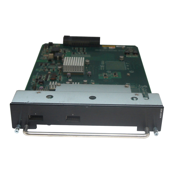
Use this Quick Reference to install or replace a 10‐Gigabit IOM
(Input/Output Module) into an available slot of an Enterasys
G‐Series switch. Refer to the Enterasys G‐Series Hardware
Installation Guide for the procedure to disconnect power and
remove the switch from a rack.
Handling the IOM
Caution: The IOM can be damaged by electrostatic discharge.
To prevent electrostatic damage, observe the following guidelines:
• Attach an ESD wrist strap to your wrist.
• Remove the IOM from its packaging only when ready to install.
• Do not touch IOM pins, connectors, or components.
• Hold the IOM by its edges or front panel only.
• Store or transport the IOM only in anti‐static packaging.
Tools
This installation requires a Phillips screwdriver.
IOM Installation Procedure
1. Remove the coverplate from the slot.
2. Insert the IOM in the guide rail of the slot. Gently slide the
module into the slot, as shown in Figure
1, until the IOM
engages the connector on the backplane and the module locks
into place and is flush with adjoining coverplates.
3. Tighten the two captive screws.
Figure 1
Installing the IOM (G3K-4XFP into Slot 2 shown)
IOM slot 2
3 Captive screw
1
2 IOM handle
4 IOM module
4. To install additional modules, remove the coverplate(s) from
the slot(s) and repeat the earlier steps. Save coverplates for
optional future use.
5. After completing all module installation, be sure to install
coverplate(s) over any unused IOM slot(s) to contain EMI
radiation and ensure proper air circulation.
Note: You must reboot the system before hot-inserted IOM modules will be
recognized. Once rebooted, module LEDs will display as described later in
this document.
IOM Removal Procedure
Caution: Do not attempt to remove an IOM module from the G-Series
switch when power is on to the switch without performing the following
procedure.
1. Disconnect any cabling from the module.
2. Loosen the module's two captive screws.
3. Press the power off button corresponding to the slot from
which you want to remove the IOM as shown in Figure
Figure 2
Chassis LEDs
1
Power Supply LEDs
3
IOM power off buttons (Slot 2, 3 and 4)
2
SYSTEM LED
4
IOM power off status LEDs (Slot 2, 3 and 4)
4. When the slot's POWER OFF status LED turns amber, gently
slide the module out of the slot.
5. Replace the slot's coverplate to contain EMI radiation and
ensure proper air circulation.
Specifications
The G3K‐2XFP and G3K‐4XFP IOMs can be installed in any
available slot of the G‐Series Ethernet switch.
Interfaces
G3K-2XFP
Two 10‐Gigabit Small Form Factor Pluggable (XFP) interfaces
G3K-4XFP
Four 10‐Gigabit Small Form Factor Pluggable (XFP) interfaces
Dimensions
Size: 4.1 H x 20.5 W x 32 D cm (handle included)
Weight: 1.1 kg (2.42 lb)
Power Consumption and Mean Time Between Failure
Power:
G3K‐2XFP = 22 W ‐ 76 BTU/HR
G3K‐4XFP = 40 W ‐ 136 BTU/HR
MTBF: G3K‐2XFP = 343,139 hours; G3K‐4XP = 246,568 hours
Temperature and Humidity
Operating: 0° to 50°C (32° to 122°F)
Storage:
‐40° to 70°C (‐40° to 158°F)
Operating relative humidity: 5% to 95% (non‐condensing)
XFP Fiber-Optic Specifications
Module
Wavelength
Max. Reach
10GBASE-LR-XFP
1310 nm DFB
10 km (6.21 mi)
10GBASE-ER-XFP
1550 nm EML
40 km (24.85 mi)
10GBASE-SR-XFP
850 nm VCSEL
300 m (1082.68 ft)
a.The limitation is receiver saturation by the transmitter. When given a signal above saturation
strength, the receiver cannot distinguish between pulses, though no hardware damage occurs.
For more XFP specifications, see the Enterasys G‐Series Hardware
Installation Guide.
Port LEDs
2.
The G‐Series XFP IOMs provide one LED per port, as described in
the following table and displayed in Figure
Display
Status
Off
No link established.
Solid Green
Ethernet link established without activity. For combo
SFP ports, this indicates power up.
Blinking Green
Ethernet link established with activity.
Figure 3
IOM LEDs (G3K-4XFP shown)
1
Port LED
2
XFP port
Getting Help
World Wide Web
www.enterasys.com/support/
Phone
1-800-872-8440 (toll-free in U.S. and Canada)
or 1-978-684-1000
To find the Enterasys Networks Support toll-free
number in your country:
www.enterasys.com/support/
Internet mail
support@enterasys.com
To expedite your message, type [Switching] in the
subject field of your message.
Latest image and
www.enterasys.com/support/downloads/
release notes
Documentation
www.enterasys.com/support/manuals/
To send comments concerning this document to the Technical
Publications Department:
techpubs@enterasys.com
Please include the document Part Number in your email message.
Before contacting Enterasys Networks for technical support, have the
following information ready:
a
Min. Reach
•
Your Enterasys Networks service contract number
2 m (6.6 ft)
•
A description of the failure
2 m (6.6 ft)
•
A description of any action(s) taken to resolve the problem
26 m (85.3 ft)
(e.g., changing mode switches, rebooting the unit)
•
The serial and revision numbers of all involved Enterasys Networks
products in the network
•
A description of your network environment (layout, cable type, etc.)
•
Network load and frame size at the time of trouble (if known)
•
The device history (i.e., have you returned the device before, is this a
recurring problem, etc.)
•
Any previous Return Material Authorization (RMA) numbers
3.
Documentation URL: http://www.enterasys.com/support/manuals
Documentacion URL: http://www.enterasys.com/support/manuals
Dokumentation URL: http://www.enterasys.com/support/manuals
Related Documents
• Enterasys G‐Series Hardware Installation Guide
• Enterasys G‐Series Configuration Guide
• Enterasys G3G‐24TX and G3G‐24SFP IOM Quick Reference
• Enterasys G‐Series Release Notes
Advertisement
Table of Contents

Related Manuals for Enterasys G3K-2XFP


Summary of Contents for Enterasys G3K-2XFP
- Page 1 Caution: Do not attempt to remove an IOM module from the G-Series a.The limitation is receiver saturation by the transmitter. When given a signal above saturation switch when power is on to the switch without performing the following strength, the receiver cannot distinguish between pulses, though no hardware damage occurs.
-
Page 2: Ethernet Switch
Federal Communications Commission (FCC) Notice This device complies with Part 15 of the FCC rules. Operation is subject to the following two conditions: (1) this device may not cause harmful interference, and (2) This table shows where these substances may be found in the supply chain of Enterasys’ electronic this device must accept any interference received, including interference that may information products, as of the date of sale of the enclosed product. Note that some of the component types cause undesired operation.
Need help?
Do you have a question about the G3K-2XFP and is the answer not in the manual?
Questions and answers