
Related Manuals for Enterasys C1H124-24


Summary of Contents for Enterasys C1H124-24
- Page 1 Matrix C1 Series Ethernet Switches C1G124-24 and C1H124-48 Installation Guide 9033831-04...
- Page 3 Enterasys Networks reserves the right to make changes in specifications and other information contained in this document and its web site without prior notice. The reader should in all cases consult Enterasys Networks to determine whether any such changes have been made.
-
Page 4: Fcc Notice
FCC NOTICE This device complies with Part 15 of the FCC rules. Operation is subject to the following two conditions: (1) this device may not cause harmful interference, and (2) this device must accept any interference received, including interference that may cause undesired operation. -
Page 5: Safety Compliance
Warning: Fiber-optic Port Safety When using a fiber-optic media expansion module, never look at the transmit laser while it is powered on. Also, never look directly at the fiber TX port and fiber cable ends when they are powered on. Avertissment: Ports pour fibres optiques - sécurité... -
Page 6: Safety Information
Wichtige Sicherheitshinweise (Germany) 1. Bitte lesen Sie diese Hinweise sorgfältig durch. 2. Heben Sie diese Anleitung für den späteren Gebrauch auf. 3. Vor jedem Reinigen ist das Gerät vom Stromnetz zu trennen. Verwenden Sie keine Flüssigoder Aerosolreiniger. Am besten eignet sich ein angefeuchtetes Tuch zur Reinigung. 4. -
Page 7: Program License Agreement
CAREFULLY READ THIS LICENSE AGREEMENT. This document is an agreement (“Agreement”) between the end user (“You”) and Enterasys Networks, Inc. on behalf of itself and its Affiliates (as hereinafter defined) (“Enterasys”) that sets forth Your rights and obligations with respect to the Enterasys software program (including any accompanying documentation, hardware or media) (“Program”) in the... - Page 8 APPLICABLE LAW. This Agreement shall be interpreted and governed under the laws and in the state and federal courts of the Commonwealth of Massachusetts without regard to its conflicts of laws provisions. You accept the personal jurisdiction and venue of the Commonwealth of Massachusetts courts. None of the 1980 United Nations Convention on Contracts for the International Sale of Goods, the United Nations Convention on the Limitation Period in the International Sale of Goods, and the Uniform Computer Information Transactions Act shall apply to this Agreement.
- Page 9 AUDIT RIGHTS. You hereby acknowledge that the intellectual property rights associated with the Program are of critical value to Enterasys and, accordingly, You hereby agree to maintain complete books, records and accounts showing (i) license fees due and paid, and (ii) the use, copying and deployment of the Program. You also grant to Enterasys and its authorized representatives, upon reasonable notice, the right to audit and examine during Your normal business hours, Your books, records, accounts and hardware devices upon which the Program may be deployed to verify compliance with this Agreement, including the verification of the license fees due and paid Enterasys and the use, copying and deployment...
-
Page 10: Declaration Of Conformity
Manufacturer’s Address: European Representative Address: Conformance to Directive(s)/Product Standards: Equipment Type/Environment: Networking Equipment, for use in a Commercial Enterasys Networks, Inc. declares that the equipment packaged with this notice conforms to the above directives. 73/23/EEC 50 Minuteman Road Andover, MA 01810 Enterasys Networks Ltd. -
Page 11: Table Of Contents
Figures ...xi Tables...xii ABOUT THIS GUIDE Who Should Use This Guide... xiii Structure of This Guide ...xiv How to Use This Guide ...xv Related Documents...xv Document Conventions...xvi INTRODUCTION Overview ... 1-1 1.1.1 Half-Duplex/Full-Duplex Auto-Negotiation ... 1-3 Port Trunking... 1-4 Remote Monitoring (RMON) ... 1-4 Port Redirect Function ... - Page 12 Installing Optional Mini-GBICs ... 3-2 Installing the Device ... 3-5 3.4.1 3.4.2 3.4.3 Connecting to the Network... 3-8 3.5.1 3.5.2 3.5.3 Connecting to Console Port for Local Management ... 3-17 3.6.1 3.6.2 3.6.3 3.6.4 3.6.5 Completing the Installation... 3-23 TROUBLESHOOTING Using LANVIEW...
-
Page 13: Figures
Figure C1H124-48 Standalone Device ... 1-2 C1G124-24 Standalone Device... 1-3 Mini-GBIC with MT-RJ Connector (C1H124-48 shown) ... 3-3 Mini-GBIC with LC Connector (C1H124-48 shown) ... 3-4 Clearance Required for Tabletop or Shelf Installation... 3-5 Attaching the Rackmount Brackets ... 3-6 Fastening the Device to the Rack ... - Page 14 Tables Table Contents of Shipping Carton...3-2 LANVIEW LEDs ...4-2 Troubleshooting Checklist...4-4 Device Specifications... A-2 Mini-GBIC Input/Output Port Specifications... A-4 MGBIC-LC01 / MGBIC-MT01 Optical Specifications ... A-4 MGBIC-LC01 / MGBIC-MT01 Operating Range ... A-5 MGBIC-LC09 Optical Specifications ... A-5 MGBIC-LC09 Operating Range ... A-5 Console Port Pin Assignments ...
-
Page 15: Important Notice
C1G124-24 devices and available options. For information about the Command Line Interface (CLI) set of commands used to configure and and manage the C1H124-48 and C1G124-24, refer to the Enterasys Networks™ Matrix C Series Configuration Guide. For information about connecting optional redundant power source, refer to the Enterasys Networks™... -
Page 16: Structure Of This Guide
Structure of This Guide STRUCTURE OF THIS GUIDE This guide is organized as follows: This preface provides preliminary information to help you use this guide and a brief summary of each chapter, defines conventions used in this document, and lists technology and user guides that may help you set up and manage the C1H124-48 and C1G124-24 and available options. -
Page 17: How To Use This Guide
HOW TO USE THIS GUIDE For... An overview of the C1H124-48 and C1G124-24 features and how to obtain technical support Network requirements that must be met before installing the device Instructions to install the device hardware Troubleshooting installation problems and diagnosing network/operational problems using the LANVIEW LEDs Specifications, environmental requirements,... -
Page 18: Document Conventions
Document Conventions DOCUMENT CONVENTIONS This guide uses the following conventions: NOTE: Calls the reader’s attention to any item of information that may be of special importance. TIP: Conveys helpful hints concerning procedures or actions. CAUTION: Contains information essential to avoid damage to the equipment. ELECTRICAL HAZARD: Warns against an action that could result in personal injury or death due to an electrical hazard. -
Page 19: Introduction
This chapter introduces the C1H124-48 and C1G124-24 standalone Ethernet switch devices. Depending on the firmware version used in the device, some features described in this document may not be supported. Refer to the Release Notes shipped with the device to determine which features are supported. -
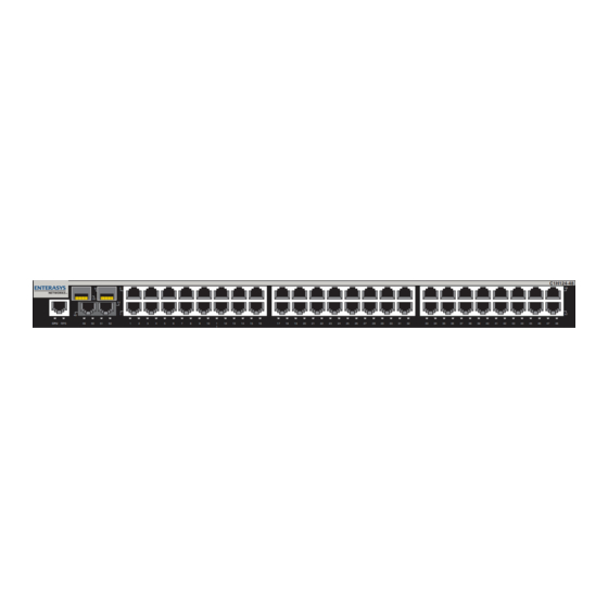
Page 20: C1H124-48 Standalone Device
C1G124-24 Figure 1-1 C1H124-48 Standalone Device Ä Â Á À Ã Redundant power supply (RPS) status LED RJ45 Console port CPU LED C1G124-24 The C1G124-24 (Figure 1-2) has several types of port connections, which include • twenty-four front panel RJ45 ports (10BASE-T/100BASE-TX/1000BASE-T compliant), and •... -
Page 21: Mini-Gigabit Interface Connectors (Mini-Gbics)
RJ45 Console port CPU LED C1H124-48 and C1G124-24 The switch functions can be configured using the WebView™ application, CLI switching commands, or SNMP. Each device can be installed as a tabletop unit or installed into a standard 19-inch rack using the mounting hardware supplied with the rack. -
Page 22: Port Trunking
Port Trunking PORT TRUNKING Port Trunking is used for load balancing or load sharing. Port Trunking provides a mechanism to group, or aggregate, multiple links of any technology together to scale the backbone bandwidth beyond the limitations of a single link. All links are user-configurable so administrators can scale the backbone bandwidth by adding Port Trunking. -
Page 23: 802.1P Port Priority
The devices support a wide variety of industry standard MIBs including RFC 1213 (MIB II), RFC 1757 (RMON), and RFC 1493 (Bridge MIB). A full suite of Enterasys Networks Enterprise MIBs provide a wide array of statistical information to enhance troubleshooting. For information on how to extract and compile individual MIBs, contact Enterasys Networks. -
Page 24: 1.11 Upn Support
UPN Support 1.11 UPN SUPPORT User Personalized Networks (UPN) is an architecture that allows network administrators to map network services to identified users, machines, peripherals and other network entities. UPN consists of three tiers: • Classification rules make up the first or bottom tier. The rules apply to devices in the UPN environment, such as switches and routers. -
Page 25: 1.12 Getting Help
1.12 GETTING HELP For additional support related to the devices or this document, contact Enterasys Networks using one of the following methods: World Wide Web http://www.enterasys.com Phone 603-332-9400 1-800-872-8440 (toll-free in U.S. and Canada) For the Enterasys Networks Support toll-free number in your country: http://www.enterasys.com/support/gtac-all.html... -
Page 27: Network Requirements
Failure to do so will produce poor network performance. NOTE: The Matrix C Series Configuration Guide and Cabling Guide referred to in the following sections can be obtained from the Enterasys Networks World Wide Web site: http://www.enterasys.com/... -
Page 28: 100Base-Tx Twisted-Pair Network
100BASE-TX Twisted-Pair Network 100BASE-TX TWISTED-PAIR NETWORK When connecting a 100BASE-TX segment to one of the fixed ports (1 through 48), or to an optional Ethernet expansion module, use Category 5 UTP cabling. The device at the other end of the twisted pair segment must meet IEEE 802.3-2002 100BASE-TX Fast Ethernet network requirements for the devices to operate at 100 Mbps. -
Page 29: Hardware Installation
ELECTRICAL HAZARD: Only qualified personnel should install the C1H124-48 and C1G124-24. NOTE: Read the Release Notes shipped with the C1H124-48 and C1G124-24 to check for any exceptions to the supported features and operation documented in this guide. This chapter provides the instructions required to install the device. Follow the order of the sections as listed below to correctly install the device. -
Page 30: Unpacking The Device
Unpacking the Device UNPACKING THE DEVICE Unpack the device as follows: 1. Open the box and remove the packing material protecting the device. 2. Verify the contents of the carton as listed in Table 3-1 Contents of Shipping Carton Item C1H124-48 or C1G124-24 Antistatic Wrist Strap Console Cable Kit... -
Page 31: Mini-Gbic With Mt-Rj Connector (C1H124-48 Shown)
To prepare and install a Mini-GBIC, proceed as follows: Preparation Before installing the Mini-GBIC, proceed as follows: 1. Attach the antistatic wrist strap (refer to the instructions in the antistatic wrist strap package) before removing the Mini-GBIC from the antistatic packaging. 2. -
Page 32: Mini-Gbic With Lc Connector (C1H124-48 Shown)
Installing Optional Mini-GBICs Figure 3-2 Mini-GBIC with LC Connector (C1H124-48 shown) À Ä Mini-GBIC (MGBIC-LC01 and MGBIC-LC09) Mini-GBIC top side 7-Pin edge connector (insertion side) Removing the Mini-GBIC CAUTION: Carefully follow the instructions in this manual to avoid damaging the Mini-GBIC and the host device (C1H124-48 The Mini-GBIC and host device are sensitive to static discharges. -
Page 33: Installing The Device
4. Grasp the sides of the Mini-GBIC If storing or shipping the Mini-GBIC, insert the dust protector into the Mini-GBIC to protect the fiber ports. INSTALLING THE DEVICE For a tabletop or shelf installation, locate the device within seven feet of its power source and on an unrestricted free surface area as shown in going to be installed and connected to the D-type cable connector on the rear of the device, refer to the installation guide shipped with the redundant power system. -
Page 34: Rackmount Installation
Installing the Device 3.4.1 Rackmount Installation To install the device in a 19-inch rack, you need: • Two rackmount brackets and mounting screws (rackmount kit) shipped with the device. • Four user-supplied screws to attach the device to a standard 19-inch rack. 3.4.1.1 Guidelines for Rackmount Installation The installation site must be within reach of the network cabling and meet the requirements listed... -
Page 35: Connecting Power
3.4.3 Connecting Power If you experience any problems with this installation, contact Enterasys Networks for assistance. NOTE: The power supply in the device has automatic voltage sensing that allows connection to power sources ranging from 100–125 Vac, 2.5 A or 200–240 Vac, 1.25 A, 50/60 Hz. -
Page 36: Connecting To The Network
Connecting to the Network Figure 3-6 Device, Rear View AC power cord AC power receptacle 3. Observe that the power (RPS) LED (not shown), located on the front panel, turns ON (green) and the CPU turns red until the device completes its initialization. It takes under 30 seconds for the device to boot up. -
Page 37: Connecting Utp Cables
3.5.1 Connecting UTP Cables The RJ45 fixed front panel ports (1 through 48) of the C1H124-48 are 10BASE-T/100BASE-TX compliant and have internal crossovers. The RJ45 fixed front panel ports (1 through 24) of the C1G124-24 are 10BASE-T/100BASE-TX/1000BASE-T compliant and have internal crossovers. When connecting a workstation to these ports, use a straight-through cable. -
Page 38: Four-Wire Crossover Cable Rj45 Pinouts For 10/100Base-Tx
Cabling Guide. Refer to on obtaining this document. 4. If a link is not established, contact Enterasys Networks. Refer to Repeat all steps above until all connections have been made. Figure 3-8 Four-Wire Crossover Cable RJ45 Pinouts for 10/100BASE-TX Ã... -
Page 39: Four-Wire Straight-Through Cable Rj45 Pinouts For 10/100Base-Tx
Figure 3-9 Four-Wire Straight-Through Cable RJ45 Pinouts for 10/100BASE-TX Ã RJ45 device port Other device port Figure 3-10 Eight-Wire Crossover Cable RJ45 Pinouts for 10/100/1000BASE-T RJ45 device port Other device port À Â RJ45-to-RJ45 straight-through cable RX+/RX- and TX+/TX- connections. These connections must share a common color pair. -
Page 40: Connecting Fiber-Optic Cables To Mt-Rj Ports
The receive strand of the applicable MT-RJ port connects to the transmit port of the fiber-optic Fast Ethernet device. Enterasys Networks recommends labeling fiber-optic cables to indicate receive and transmit ends. Many cables are pre-labeled, providing matching labels or tapes at both ends of each strand of cable. -
Page 41: Cable Connection To Mt-Rj Multimode Fiber-Optic Connectors
To connect an MT-RJ cable to a fixed MT-RJ connector of a Mini-GBIC, refer to proceed as follows: 1. Remove the protective covers (not shown) from the front panel MT-RJ fiber-optic port 52 in this example) and from the connectors NOTE: Leave the protective covers in place when the connectors are not in use to prevent contamination. -
Page 42: Connecting Fiber-Optic Cables To Lc Ports
The receive strand of the applicable LC port connects to the transmit port of the fiber-optic Fast Ethernet device. 3-14 Hardware Installation Chapter 4 for LED troubleshooting details. If a Section 1.12 for details on contacting Enterasys Networks for support. is on (blinking green or “Related... - Page 43 Enterasys Networks recommends labeling fiber-optic cables to indicate receive and transmit ends. Many cables are pre-labeled, providing matching labels or tapes at both ends of each strand of cable. To connect an LC cable connector to a fixed LC connector of a Mini-GBIC, refer to and proceed as follows: 1.
-
Page 44: Cable Connection To Lc Multimode Fiber-Optic Connectors
5. Repeat steps 1 through 3, above, until all connections have been made. 3-16 Hardware Installation Á Â Chapter 4 for LED troubleshooting details. If a Section 1.12 for details on contacting Enterasys Networks for support. À Ã Release tab Link/Activity LED is on (blinking green or “Related... -
Page 45: Connecting To Console Port For Local Management
This section describes how to install a UTP straight-through cable with RJ45 connectors and optional adapters to connect a PC, a VT series terminal, or a modem to an Enterasys Networks module to access CLI commands. This section also provides the pinout assignments of the adapters. -
Page 46: Connecting To A Vt Series Terminal
RJ45 Console port shown on C1H124-48 3.6.3 Connecting to a VT Series Terminal To connect a VT Series terminal to an Enterasys Networks device Console port a UTP straight-through cable with RJ45 connectors and an optional RJ45-to-DB25 female adapter, and proceed as follows: 1. -
Page 47: Connecting To A Modem
RJ45 Console port shown on C1H124-48 3.6.4 Connecting to a Modem To connect a modem to an Enterasys Networks device modem port straight-through cable with RJ45 connectors and an optional RJ45-to-DB25 male adapter, and proceed as follows: 1. Connect the RJ45 connector at one end of the cable Networks device. -
Page 48: Connecting To A Modem
Connecting to Console Port for Local Management 5. Configure your VT emulation package with the following parameters: Parameter Mode Transmit Bits Parity Stop Bit When these parameters are set, the Startup screen will display. Proceed to the installation. Figure 3-16 Connecting to a Modem UTP straight-through cable with RJ45 connectors RJ45 Console port on C1H124-48... -
Page 49: Adapter Wiring And Signal Assignments
3.6.5 Adapter Wiring and Signal Assignments Console Port Adapter Wiring and Signal Diagram RJ45 VT Series Port Adapter Wiring and Signal Diagram RJ45 Connecting to Console Port for Local Management Conductor Blue Green Orange Yellow DB25 Conductor Blue Yellow Green Orange Signal Receive (RX) - Page 50 Connecting to Console Port for Local Management Modem Port Adapter Wiring and Signal Diagram RJ45 Conductor Blue Orange Green Yellow Gray 3-22 Hardware Installation DB25 Signal Transmit (TX) Data Carrier Detect (DCD) Receive Ground (GRD) Data Terminal Ready (DTR) Ring Indicator...
-
Page 51: Completing The Installation
COMPLETING THE INSTALLATION After installing the Enterasys Networks device and making the connections to the network, proceed as follows: Initial Logon to Device Management To initially access device management from your local pc, terminal, or modem connection, proceed as follows at the displayed startup screen: Enter rw (Read-Write) for Username. -
Page 53: Troubleshooting Checklist
LED indications and provides recommended actions as appropriate. 4.1) (Section 4.2) 4.3) Figure 4-1) and the C1G124-24 use the Enterasys Networks built-in À Ã Á Â RPS LED for redundant power source status Link/Activity LED for 10/100 Mbps RJ45 port 1 Troubleshooting Ä... - Page 54 Recommended Action If the LED remains red for several minutes, the system may have a fatal error. Contact Enterasys Networks for technical support. If the LED remains amber for more than several minutes, contact Enterasys Networks for technical support.
- Page 55 C1H124-48, note the display of its LED indicators for power status indications. Correct problem as necessary. 3. Contact Enterasys Networks for technical support. 1. Ensure that the power cords are plugged in correctly and that there is power at the two power sources.
-
Page 56: Troubleshooting Checklist
Guide for the Community Names Table setup. If the Community Names have been forgotten, refer to Matrix C Series Configuration Guide for instructions on how to set the mode switch to reset the Community Names to their default values. for proper Console port... - Page 57 Table 4-2 Troubleshooting Checklist (Continued) Problem Possible Cause Cannot contact IP address not assigned. the device through in-band management. Port is disabled. No link to device. Port(s) goes into Loop condition detected. standby for no apparent reason. User parameters Clear NVRAM was set (IP address, using CLI commands.
-
Page 58: Using The Reset Button
Series Configuration Guide. The CLI commands enable you to initially set up and perform more involved switch management configurations. The guide is available online at: http://www.enterasys.com/support/manuals If you require assistance, contact Enterasys Networks using one of the methods described in Section 1.12. Troubleshooting Á... -
Page 59: Specifications
• Optional Mini-GBIC input/output port specifications • Gigabit Ethernet (Section • Console Port pinout assignment • Regulatory compliance Enterasys Networks reserves the right to change the specifications at any time without notice. (Section A.3) (Section A.4) (Section A.5) Specifications A.1) (Section A.2) -
Page 60: A.1 C1G124-24 And C1H124-48 Specifications
C1G124-24 and C1H124-48 Specifications C1G124-24 AND C1H124-48 SPECIFICATIONS Table A-1 provides the I/O ports, processors and memory, physical, and environmental specifications for the C1G124-24 and C1H124-48. Table A-1 Device Specifications Item C1G124-24 I/O Ports Ports 1 through 24 (21 through 24 are either/ or shared with Mini-GBIC ports slots 21 through 24) Ports 21 and 24 (Mini-GBIC option slots) are... - Page 61 Table A-1 Device Specifications (Continued) Item Redundant Power Source Connector External Power Connector on rear of the C1G124-24 and C1H124-48 Physical Dimensions Shipping Weight (one device per carton) Net weight MTBF (calculated): C1H124-48 C1G124-24 Environmental Operating Temperature Storage Temperature Operating Relative Humidity C1G124-24 and C1H124-48 Specifications Specification 15-pin D-type connector for an optional dc...
-
Page 62: Mini-Gbic Input/Output Specifications
Mini-GBIC Input/Output Specifications MINI-GBIC INPUT/OUTPUT SPECIFICATIONS The Mini-Gigabit Ethernet Card (Mini-GBIC) port expansion slots can accept 1000BASE-SX short wavelength or 1000BASE-LX long wavelength fiber-optic Mini-GBICs (refer to optional Mini-GBICs are hot swappable. WARNING: Mini-GBICs use Class 1 lasers. Do not use optical instruments to view the laser output. -
Page 63: A-4 Mgbic-Lc01 / Mgbic-Mt01 Operating Range
Table A-4 MGBIC-LC01 / MGBIC-MT01 Operating Range Item 62.5 µm MMF 62.5 µm MMF 50 µm MMF 50 µm MMF A.3.2 MGBIC-LC09 Specifications (1000BASE-LX) Table A-5 MGBIC-LC09 Optical Specifications Item Transmit Power (minimum) Receive Sensitivity Link Power Budget Table A-6 MGBIC-LC09 Operating Range Item 62.5 µm MMF 50 µm MMF... -
Page 64: A.5 Regulatory Compliance
Console Port Pinout Assignments CONSOLE PORT PINOUT ASSIGNMENTS The Console port is a serial communications port that supports local management of the C1H124-48 and C1G124-24. These pin assignments differ from other Enterasys products. Refer to for the Console port pin assignments. Table A-7 Console Port Pin Assignments Signal Name Transmit Data (TD)
Need help?
Do you have a question about the C1H124-24 and is the answer not in the manual?
Questions and answers