Sign In
Upload
Manuals
Brands
Cisco Manuals
Multiplexer
ONS 15454 DWDM
Cisco ONS 15454 DWDM Manuals
Manuals and User Guides for Cisco ONS 15454 DWDM. We have
4
Cisco ONS 15454 DWDM manuals available for free PDF download: Installation And Operation Manual, Reference Manual, Manual
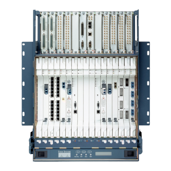
Cisco ONS 15454 DWDM Installation And Operation Manual (954 pages)
Brand:
Cisco
| Category:
Chassis
| Size: 18.06 MB
Table of Contents
Table of Contents
4
About this Guide
55
Revision History
55
Document Objectives
56
Related Documentation
57
Before You Begin
63
DLP-G2 Inspect the Shelf Assembly
69
NTP-G2 Install the Shelf Assembly
70
DLP-G3 Reverse the Mounting Bracket to Fit a 19-Inch (482.6-MM) Rack (ANSI Only)
72
DLP-G4 Install the External Brackets and Air Filter (ANSI Only)
73
Figure 1-1 Reversing the Mounting Brackets (23-Inch [584.2-MM] Position to 19-Inch [482.6-MM] Position)
73
Figure 1-2 Installing the External Brackets
74
DLP-G5 Mount the Shelf Assembly in a Rack (One Person)
75
Figure 1-3 Mounting an ONS 15454 ETSI in a Rack
76
DLP-G6 Mount the Shelf Assembly in a Rack (Two People)
77
DLP-G7 Mount Multiple Shelf Assemblies in a Rack
78
Figure 1-4 Three-Shelf ONS 15454 ETSI (15454 SDH) Bay Assembly
80
DLP-G8 Install the Air Ramp
81
NTP-G3 Open and Remove the Front Door
82
DLP-G9 Open the Front Cabinet Compartment (Door)
82
DLP-G10 Remove the Front Door
83
Figure 1-7 Removing the ONS 15454 ETSI Front Door
84
NTP-G4 Open and Remove the FMEC Cover (ETSI Only)
85
DLP-G11 Open the FMEC Cover
86
DLP-G12 Remove the FMEC Cover
87
Figure 1-10 Removing the ONS 15454 FMEC Cover
87
NTP-G5 Remove the Backplane Covers (ANSI Only)
88
DLP-G13 Remove the Lower Backplane Cover
88
DLP-G14 Remove the Backplane Sheet Metal Cover
89
NTP-G6 Install the MIC-A/P and MIC-T/C/P Fmecs (ETSI Only)
89
Figure 1-11 Installing Fmecs on the ONS 15454 ETSI
91
NTP-G7 Install the Power and Ground
92
DLP-G15 Connect the Office Ground to the ONS 15454 ETSI
94
DLP-G16 Connect the Office Ground to the ONS 15454 ANSI
95
Figure 1-12 Grounding the ONS 15454 ETSI
95
Figure 1-13 Ground Location on the Backplane
96
DLP-G17 Connect Office Power to the ONS 15454 ETSI
97
Table 1-1 Pin Connection of the Power Fmecs
98
DLP-G18 Connect Office Power to the ONS 15454 ANSI
99
Figure 1-14 Cisco ONS 15454 Power Terminals
100
DLP-G19 Turn on and Verify Office Power
101
NTP-G8 Install the Fan-Tray Assembly
102
Figure 1-15 Installing the Fan-Tray Assembly on the ONS 15454 ETSI
104
Figure 1-16 Installing the Fan-Tray Assembly on the ONS 15454 ANSI
105
NTP-G9 Install the Alarm Expansion Panel (ANSI Only)
106
Figure 1-17 Replace Backplane Screws with Standoffs
107
Figure 1-18 Installing Standoffs and the AEP
108
Figure 1-19 AEP Wire-Wrap Connections to Backplane Pins
108
NTP-G10 Attach Wires to Alarm, Timing, LAN, and Craft Pin Connections
109
Table 1-2 Pin Assignments for the AEP
109
DLP-G20 Install Alarm Wires on the MIC-A/P (ETSI Only)
110
Table 1-3 Alarm Pin Assignments
111
DLP-G21 Install Timing Wires on the MIC-C/T/P (ETSI Only)
113
Table 1-4 MIC-C/T/P Clock Connector Pin Assignment
113
DLP-G22 Install LAN Wires on the MIC-C/T/P (ETSI Only)
114
Table 1-5 LAN Pin Assignments
114
DLP-G23 Install Alarm Wires on the Backplane (ANSI Only)
115
Figure 1-20 Cisco ONS 15454 Backplane Pinouts (Release 3.4 or Later)
117
DLP-G24 Install Timing Wires on the Backplane (ANSI Only)
118
Figure 1-21 Highlighted Environmental Alarms
118
Table 1-6 External Timing Pin Assignments for BITS
118
DLP-G25 Install LAN Wires on the Backplane (ANSI Only)
119
DLP-G26 Install the TL1 Craft Interface (ANSI Only)
120
Table 1-7 LAN Pin Assignments for the ONS 15454 ANSI Shelf
120
NTP-G11 Install an External Wire-Wrap Panel on the AEP (ANSI Only)
121
Table 1-8 Craft Interface Pin Assignments
121
Figure 1-22 Installing the AEP Cover
122
Table 1-9 Alarm Input Pin Assignments
122
Table 1-10 Alarm Output Pin Assignments
123
Figure 1-23 Alarm Input Connector
124
Figure 1-24 Alarm Output Connector
125
NTP-G12 Install and Close the FMEC Cover (ETSI Only)
125
Figure 1-25 ONS 15454 ETSI FMEC Cover
126
Figure 1-26 Backplane Attachment for the Rear Cover
127
NTP-G13 Install the Rear Cover (ANSI Only)
127
NTP-G14 Install DWDM Equipment
128
Figure 1-27 Installing the Rear Cover with Spacers
128
DLP-G27 Install the DCU Shelf Assembly
129
DLP-G28 Install the Fiber Patch Panel Shelf
130
DLP-G29 Install the Fiber Storage Shelf
130
DLP-G30 Install the Flexlayer Shelf
131
DLP-G31 Install the Flexlayer Modules
131
Table 1-11 ONS 15Xxx Flexlayer Hardware Part Numbers
132
DLP-G32 Install the Y-Cable Protection Modules
133
Figure 1-28 ONS 15Xxx Flexlayer Shelf Assembly
133
NTP-G15 Install the Common Control Cards
134
DLP-G33 Install the TCC2 Card
135
Figure 1-29 Installing Cards in the ONS 15454 ETSI
135
DLP-G34 Install the AIC or AIC-I Card
138
NTP-G16 Perform the Shelf Installation Acceptance Test
139
Table 1-12 ONS 15454 ETSI Shelf Installation Task Summary
139
DLP-G35 Inspect the Shelf Installation and Connections
140
Table 1-13 ONS 15454 ANSI Shelf Installation Task Summary
140
DLP-G36 Measure Voltage
141
Connect the PC and Log into the GUI
143
Before You Begin
143
NTP-G17 Set up Computer for CTC
144
DLP- G37 Run the CTC Installation Wizard for Windows 2-3
145
Chapter 2 Connect the PC and Log into the GUI
145
DLP-G38 Run the CTC Installation Wizard for UNIX
148
NTP-G18 Set up CTC Computer for Local Craft Connection to the ONS 15454
151
Table 2-1 CTC Computer Setup for Local Craft Connections to the ONS 15454
151
DLP-G39 Set up a Windows PC for Craft Connection to an ONS 15454 on the same Subnet Using Static IP Addresses
153
DLP-G40 Set up a Windows PC for Craft Connection to an ONS 15454 Using Dynamic Host Configuration Protocol
155
Detection
157
DLP-G42 Set up a Solaris Workstation for a Craft Connection to an ONS 15454
160
NTP-G19 Set up a CTC Computer for a Corporate LAN Connection to the ONS 15454
162
DLP-G43 Disable Proxy Service Using Internet Explorer (Windows)
163
DLP-G44 Disable Proxy Service Using Netscape (Windows and UNIX)
163
NTP-G20 Set up a Remote Access Connection to the ONS 15454
164
NTP-G21 Log into the ONS 15454 GUI
165
DLP-G45 Connect Computer to the ONS 15454
166
DLP-G46 Log into CTC
167
DLP-G47 Install Public-Key Security Certificate
170
DLP-G48 Create Login Node Groups
171
DLP-G49 Add a Node to the Current Session or Login Group
172
Figure 2-2 Login Node Group
172
DLP-G50 Delete a Node from the Current Session or Login Group
173
DLP-G51 Delete a Node from a Specified Login Node Group
173
DLP-G52 Change the JRE Version
174
DLP-G53 Configure the CTC Alerts Dialog Box for Automatic Popup
175
Chapter 3 Turn up a Node
177
Before You Begin
177
NTP-G22 Verify Common Card Installation
178
NTP-G23 Create Users and Assign Security
179
DLP-G54 Create a New User-Single Node
180
DLP-G55 Create a New User-Multiple Nodes
180
NTP-G24 Set up Name, Date, Time, and Contact Information
182
NTP-G25 Set Power Monitor Thresholds
184
NTP-G26 Set up CTC Network Access
184
DLP-G56 Provision IP Settings
185
Table 3-1 LED Behavior During TCC2 Reboot
188
DLP-G57 Set the IP Address, Default Router, and Network Mask Using the LCD
189
Figure 3-3 Selecting the Save Configuration Option
190
Figure 3-4 Saving and Rebooting the TCC2/TCC2P
190
DLP-G58 Create a Static Route
191
DLP-G59 Set up or Change Open Shortest Path First Protocol
192
DLP-G60 Set up or Change Routing Information Protocol
194
NTP-G27 Set up the ONS 15454 for Firewall Access
195
Figure 3-5 Nodes Behind a Firewall
195
DLP-G61 Provision the IIOP Listener Port on the ONS 15454
196
Figure 3-6 CTC Computer and ONS 15454S Residing Behind Firewalls
196
Table 3-2 Ports Used by the TCC2 Cards
197
DLP-G62 Provision the IIOP Listener Port on the CTC Computer
198
NTP-G28 Set up SNMP
198
Figure 3-7 Creating an SNMP Trap
199
NTP-G29 Preprovision a Slot
200
Figure 3-8 Cisco Metroplanner Site Dialog Window
201
NTP-G30 Install the DWDM Cards
202
NTP-G31 Install the DWDM Dispersion Compensating Units
204
NTP-G32 Install the Transponder and Muxponder Cards
206
DLP-G63 Install an SFP
208
DLP-G64 Remove an SFP
208
NTP-G33 Create a Y-Cable Protection Group
209
Table 3-3 Protection Types
209
Figure 3-9 Creating a Y-Cable Protection Group
210
NTP-G34 Install Fiber-Optic Cables on DWDM Cards
211
Figure 3-10 Cisco Metroplanner Internal Connections Table
212
DLP-G65 Install Fiber-Optic Cables for OSC Link Terminations on All Nodes
213
Figure 3-11 Fibering OSC Terminations-Hub Node with OSCM Cards
215
DLP-G66 Install Fiber-Optic Cables for a Hub Node
216
Figure 3-12 Fibering a Hub Node
218
DLP-G67 Install Fiber-Optic Cables for a Terminal Node
219
DLP-G68 Install Fiber-Optic Cables for a Line Amplifier Node
220
Figure 3-13 Fibering a Line Amplifier Node
221
DLP-G69 Install Fiber-Optic Cables for an OSC Regeneration Node
222
Figure 3-14 Fibering an OSC Regeneration Node
223
DLP-G70 Install Fiber-Optic Cables for an Amplified or Passive OADM Node
224
Figure 3-15 Fibering an Amplified OADM Node
226
Figure 3-16 Fibering a Passive OADM Node
228
DLP-G71 Install Fiber-Optic Cables for an ROADM Node
229
Figure 3-17 Fibering an ROADM Node
230
NTP-G35 Route Fiber-Optic Cables
231
NTP-G36 Calculate Cable Connections
232
DLP-G72 Create a DWDM Connection
233
DLP-G73 Delete a DWDM Connection
233
NTP-G37 Run Automatic Node Setup
234
DLP-G74 Import a Cisco Metroplanner Configuration File
235
NTP-G38 Provision Terminations and Ring ID
236
DLP-G75 Create OSC Terminations
237
Figure 3-18 OSC Terminations Pane
237
DLP-G76 Provision GCC Terminations
238
DLP-G77 Provision the Ring ID
239
NTP-G39 Verify OSCM and OSC-CSM Transmit Power
239
NTP-G40 Replace the Front Door
240
Figure 3-19 Installing the Door Ground Strap Retrofit Kit
241
Figure 3-20 Shelf Assembly with Door Ground Strap Retrofit Kit Installed
242
Perform Node Acceptance Tests
243
Before You Begin
243
Chapter 4 Perform Node Acceptance Test
244
NTP-G42 Perform the Terminal Node with 32WSS and 32DMX Cards Acceptance Test
246
NTP-G43 Perform the ROADM Node Acceptance Test
248
NTP-G44 Perform the Anti-ASE Hub Node Acceptance Test
250
NTP-G45 Perform the Symmetric Line Node with OSCM Cards Acceptance Test
252
NTP-G46 Perform the Symmetric Line Node with OSC-CSM Cards Acceptance Test
254
NTP-G47 Perform the Asymmetric Line Node with OSC-CSM and OSCM Cards Acceptance Test
255
NTP-G48 Perform the Symmetric OADM Node with OSCM Cards Acceptance Test
258
NTP-G49 Perform the Symmetric OADM Node with OSC-CSM Cards Acceptance Test
260
NTP-G50 Perform the Symmetric Passive OADM Node with OSC-CSM Cards Acceptance Test
262
DLP-G78 Verify the 32MUX-O and 32DMX-O Power
264
DLP-G79 Verify the OPT-BST Amplifier Laser and Power
264
DLP-G80 Verify the OPT-PRE Amplifier Laser and Power
265
DLP-G81 Verify the 32DMX-O or 32DMX Power
266
DLP-G82 Verify the OSC-CSM Power
266
DLP-G83 Verify the OSC-CSM Power-OADM Nodes
267
DLP-G84 Verify the OSC-CSM Incoming Power
267
DLP-G85 Verify Express Channel Connections-OADM Node with OSCM Cards
268
DLP-G86 Verify Express Channel Connections-OADM Node with OSC-CSM Cards
269
DLP-G87 Verify the AD-Xb-XX.X Output Express Power
270
DLP-G88 Verify the AD-XC-XX.X Output Express Power
270
DLP-G89 Verify OADM Node Pass-Through Channel Connections
271
DLP-G90 Verify an AD-Xb-XX.X Pass-Through Connection Power
272
DLP-G91 Verify an AD-XC-XX.X Pass-Through Connection
273
DLP-G92 Verify an 4MD-XX.X Pass-Through Connection Power
274
DLP-G93 Verify Add and Drop Connections on OADM Node with OSCM Card
275
DLP-G94 Verify Add and Drop Connections on OADM Node with OSC-CSM Card
277
Before You Begin
281
NTP-G51 Verify DWDM Node Turn up
282
NTP-G52 Verify Node-To-Node Connections
283
Chapter 5 Turn up Network
283
NTP-G53 Set up Timing
284
DLP-G95 Set up External or Line Timing
284
DLP-G96 Set up Internal Timing
286
NTP-G54 Provision and Verify a DWDM Network
287
DLP-G97 Provision a Proxy Tunnel
290
DLP-G98 Provision a Firewall Tunnel
291
DLP-G99 Create a Provisionable Patchcord
292
NTP-G55 Verify the Optical Receive Power
293
NTP-G56 Verify the OSNR
294
NTP-G57 Create a Logical Network Map
295
Before You Begin
297
NTP-G58 Locate and View Optical Channel Network Connections
298
DLP-G100 Search for Optical Channel Network Connections
298
Chapter 6 Create Channel and Circuit
298
DLP-G101 View Optical Channel Network Connection Information
299
Table 6-1 Circuit Protection Types
301
Table 6-2 Cisco ONS 15454 Circuit Status
301
DLP-G102 Filter the Display of Optical Channel Network Connections
302
DLP-G103 View Optical Channel Network Connections on a Span
303
NTP-G59 Create and Delete Optical Channel Network Connections
304
DLP-G104 Assign a Name to a Port
304
DLP-G105 Provision DWDM Optical Channel Network Connections
305
Table 6-3 OCHNC Channels
305
DLP-G106 Delete Optical Channel Network Connections
307
NTP-G60 Create Overhead Circuits
308
DLP-G107 Create an IP-Encapsulated Tunnel
309
DLP-G108 Change the Service State for a Port
310
DLP-G109 Provision Orderwire
311
DLP-G110 Create a User Data Channel Circuit
312
NTP-G61 Modify and Delete Overhead Circuits
313
DLP-G111 Repair an IP Tunnel
313
DLP-G112 Delete Overhead Circuits
314
NTP-G62 Create a J0 Section Trace
314
Before You Begin
317
Manage Alarms
318
NTP-G63 Document Existing Provisioning
318
DLP-G113 Print CTC Data
318
Figure 7-1 Selecting CTC Data for Print
319
Chapter 7 Manage Alarm
319
DLP-G114 Export CTC Data
320
NTP-G64 View Alarms, History, Events, and Conditions
321
DLP-G115 View Alarms
322
Figure 7-3 CTC Node View
323
Table 7-1 Alarm Column Descriptions
323
DLP-G116 View Alarm or Event History
324
Table 7-2 Color Codes for Alarms and Condition Severities
324
DLP-G117 Change the Maximum Number of Session Entries for Alarm History
326
DLP-G118 Display Alarms and Conditions Using Time Zone
327
DLP-G119 Synchronize Alarms
327
DLP-G120 View Conditions
328
NTP-G65 Delete Cleared Alarms from Display
329
NTP-G66 View Alarm-Affected Circuits
330
Figure 7-6 Select Affected Circuits Option
331
NTP-G67 View Alarm Counts on the LCD for a Node, Slot, or Port
332
NTP-G68 Create, Download, and Assign Alarm Severity Profiles
333
Figure 7-8 Shelf LCD Panel
333
DLP-G121 Create a New or Cloned Alarm Severity Profile
334
Figure 7-9 Store Profiles Dialog Box
337
DLP-G122 Download an Alarm Severity Profile
338
DLP-G123 Apply Alarm Profiles to Ports
339
Figure 7-10 AD-1C Card Alarm Profile
341
DLP-G124 Apply Alarm Profiles to Cards and Nodes
342
Figure 7-11 Node View Alarm Profile
342
DLP-G125 Delete Alarm Severity Profiles
343
Figure 7-12 Select Node/Profile Combination for Delete Dialog Box
344
NTP-G69 Enable, Modify, or Disable Alarm Severity Filtering
345
DLP-G126 Enable Alarm Filtering
345
DLP-G127 Modify Alarm, Condition, and History Filtering Parameters
346
Figure 7-13 Alarm Filter Dialog Box General Tab
347
Figure 7-14 Alarm Filter Dialog Box Conditions Tab
347
DLP-G128 Disable Alarm Filtering
348
NTP-G70 Suppress Alarms or Discontinue Alarm Suppression
349
DLP-G129 Suppress Alarm Reporting
349
DLP-G130 Discontinue Alarm Suppression
351
NTP-G71 Provision External Alarms and Controls on the Alarm Interface Controller Card
352
Figure 7-15 AIC Card External Alarms
353
NTP-G72 Provision External Alarms and Controls on the Alarm Interface Controller-International
354
Figure 7-16 Provisioning External Alarms on the AIC-I Card
356
Monitor Performance
359
Before You Begin
359
NTP-G73 Change the PM Display
360
DLP-G131 Refresh PM Counts at 15-Minute Intervals
360
Chapter 8 Monitor Performance
360
DLP-G132 Refresh PM Counts at One-Day Intervals
361
DLP-G133 View Near-End PM Counts
362
DLP-G134 View Far-End PM Counts
362
DLP-G135 Reset Current PM Counts
363
DLP-G136 Clear Selected PM Counts
364
DLP-G137 Set Auto-Refresh Interval for Displayed PM Counts
364
DLP-G138 Refresh PM Counts for a Different Port
365
NTP-G74 Monitor DWDM Card Performance
366
DLP-G139 View Optical Service Channel PM Parameters
366
Figure 8-1 OC3 Line Tab in the Optical Service Channel Card View Performance Window
367
DLP-G140 View Optical Amplifier PM Parameters
368
DLP-G141 View Pms for 32MUX-O, 32-WSS, 32-DMX-O, and 32DMX Cards
369
DLP-G142 View Channel Filter Optical Add/Drop Multiplexer PM Parameters
370
Figure 8-4 Optical Line Tab in the Channel Filter OADM Card View Performance Window
371
DLP-G143 View Band Filter Optical Add/Drop Multiplexer PM Parameters
372
NTP-G75 Monitor Transponder and Muxponder Performance
373
DLP-G144 Enable/Disable OTN ITU-T G.709 Performance Monitoring
374
DLP-G145 Enable/Disable OTN FEC Performance Monitoring
375
DLP-G146 View Optics PM Parameters
376
DLP-G147 View Payload PM Parameters
377
Figure 8-8 Viewing Optics Performance Monitoring Information
377
Figure 8-9 Viewing Payload Performance Monitoring Information
378
DLP-G148 View OTN PM Parameters
379
Figure 8-10 Viewing OTN ITU-T G.709 Performance Monitoring Information
379
DLP-G149 View Payload Statistics PM Parameters
380
Figure 8-11 Viewing OTN FEC Performance Monitoring Information
380
Figure 8-12 Statistics Tab on the Card View Performance Window
381
DLP-G150 View Payload Utilization PM Parameters
382
Figure 8-13 Utilization Tab on the Card View Performance Window
382
DLP-G151 View Payload History PM Parameters
383
DLP-G152 View Payload SONET PM Parameters
384
Figure 8-14 History Tab on the Card View Performance Window
384
Figure 8-15 SONET PM Tab on the Card View Performance Window
385
DLP-G153 Create RMON Alarm Thresholds
386
DLP-G154 Delete RMON Alarm Thresholds
388
Advertisement
Cisco ONS 15454 DWDM Installation And Operation Manual (1218 pages)
Brand:
Cisco
| Category:
Multiplexer
| Size: 21.72 MB
Table of Contents
Table of Contents
4
Cisco ONS 15454 DWDM Installation and Operations Guide
38
About this Guide
65
Revision History
65
Related Documentation
67
Test Equipment (ETSI)
86
DLP- G2 Inspect the Shelf Assembly
87
NTP- G2 Install the Shelf Assembly
88
DLP- G3 Reverse the Mounting Bracket to Fit a 19-Inch (482.6-MM) Rack (ANSI Only)
90
DLP- G4 Install the External Brackets and Air Filter (ANSI Only)
91
Figure 1-2 Installing the External Brackets
92
DLP- G5 Mount the Shelf Assembly in a Rack (One Person)
93
Figure 1-3 Mounting an ONS 15454 ETSI in a Rack
94
DLP- G6 Mount the Shelf Assembly in a Rack (Two People)
95
DLP- G7 Mount Multiple Shelf Assemblies in a Rack
96
Figure 1-4 Three-Shelf ONS 15454 ETSI (15454 SDH) Bay Assembly
98
DLP- G8 Install the Air Ramp
99
Figure 15-25 Backplane Covers
100
NTP- G3 Open and Remove the Front Door
100
DLP- G10 Remove the Front Door
101
Figure 1-7 Removing the ONS 15454 ETSI Front Door
102
NTP- G4 Open and Remove the FMEC Cover (ETSI Only)
103
DLP- G11 Open the FMEC Cover
104
DLP- G12 Remove the FMEC Cover
105
NTP- G5 Remove the Backplane Covers (ANSI Only)
106
Figure
107
DLP- G14 Remove the Backplane Sheet Metal Cover
107
NTP- G6 Install the MIC-A/P and MIC-T/C/P Fmecs (ETSI Only)
108
Figure 1-12 Installing Fmecs on the ONS 15454 ETSI
109
NTP- G7 Install the Power and Ground
110
DLP- G15 Connect the Office Ground to the ONS 15454 ETSI
112
Figure 1-13 Grounding the ONS 15454 ETSI
113
DLP- G16 Connect the Office Ground to the ONS 15454 ANSI
114
Figure
114
DLP- G17 Connect Office Power to the ONS 15454 ETSI
115
Table 1-1 Pin Connection of the Power Fmecs
116
DLP- G18 Connect Office Power to the ONS 15454 ANSI
117
Figure 1-15 Cisco ONS 15454 Power Terminals
118
DLP- G19 Turn on and Verify Office Power
119
NTP- G8 Install the Fan-Tray Assembly
120
Figure 1-16 Installing the Fan-Tray Assembly on the ONS 15454 ETSI
122
Figure 1-17 Installing the Fan-Tray Assembly on the ONS 15454 ANSI
123
NTP- G9 Install the Alarm Expansion Panel (ANSI Only)
124
Replace Backplane Screws with Standoffs
125
Figure 1-19 Installing Standoffs and the AEP
126
Figure 1-20 AEP Wire-Wrap Connections to Backplane Pins
126
NTP- G10 Attach Wires to Alarm, Timing, LAN, and Craft Pin Connections
127
DLP- G20 Install Alarm Wires on the MIC-A/P (ETSI Only)
128
Table 1-3 Alarm Pin Assignments
129
DLP- G21 Install Timing Wires on the MIC-C/T/P (ETSI Only)
131
Table 1-4 MIC-C/T/P Clock Connector Pin Assignment
131
DLP- G22 Install LAN Wires on the MIC-C/T/P (ETSI Only)
132
Table 1-5 LAN Pin Assignments
132
DLP- G23 Install Alarm Wires on the Backplane (ANSI Only)
133
Table 1-2 Pin Assignments for the AEP
127
Cisco ONS 15454 Backplane Pinouts (Release 3.4 or Later)
134
DLP- G24 Install Timing Wires on the Backplane (ANSI Only)
135
DLP- G25 Install LAN Wires on the Backplane (ANSI Only)
136
DLP- G26 Install the TL1 Craft Interface (ANSI Only)
137
NTP- G11 Install an External Wire-Wrap Panel on the AEP (ANSI Only)
138
Figure 1-23 Installing the AEP Cover
139
Table 1-9 Alarm Input Pin Assignments
139
Table 1-10 Alarm Output Pin Assignments
140
Alarm Input Connector
141
Figure 1-25 Alarm Output Connector
142
NTP- G12 Install and Close the FMEC Cover (ETSI Only)
143
Figure 1-27 Backplane Attachment for the Rear Cover
144
NTP- G13 Install the Rear Cover (ANSI Only)
144
Figure 1-28 Installing the Rear Cover with Spacers
145
NTP- G14 Install DWDM Equipment
146
DLP- G27 Install the DCU Shelf Assembly
147
DLP- G29 Install the Fiber-Storage Tray
148
DLP- G31 Install the Flexlayer Modules
149
Table 1-11 ONS 15Xxx Flexlayer Hardware Part Numbers
149
DLP- G32 Install the Y-Cable Protection Modules
150
NTP- G15 Install the Common Control Cards
151
DLP- G33 Install the TCC2 or TCC2P Card
152
DLP- G34 Install the AIC-I Card
155
Table 1-12 ONS 15454 ETSI Shelf Installation Task Summary
156
Table 1-13 ONS 15454 ANSI Shelf Installation Task Summary
156
NTP- G16 Perform the Shelf Installation Acceptance Test
156
DLP- G35 Inspect the Shelf Installation and Connections
157
DLP- G36 Measure Voltage
158
Before You Begin
159
Figure
160
Chapter 2 Connect the PC and Log into the GUI
161
DLP- G38 Run the CTC Installation Wizard for UNIX
164
NTP- G18 Set up CTC Computer for Local Craft Connection to the ONS 15454
167
Figure
168
Table 2-1 CTC Computer Setup for Local Craft Connections to the ONS 15454
168
Figure
169
DLP- G40 Set up a Windows PC for Craft Connection to an ONS 15454 Using Dynamic Host Configuration Protocol
171
Figure
174
Figure
177
NTP- G19 Set up a CTC Computer for a Corporate LAN Connection to the ONS 15454
179
DLP- G43 Disable Proxy Service Using Internet Explorer (Windows)
180
NTP- G20 Set up a Remote Access Connection to the ONS 15454
181
Figure
182
DLP- G46 Log into CTC
183
Figure 2-1 Logging into CTC
184
DLP- G47 Install Public-Key Security Certificate
186
Figure 2-2 Login Node Group
187
DLP- G49 Add a Node to the Current Session or Login Group
188
DLP- G51 Delete a Node from a Specified Login Node Group
189
Figure
190
Before You Begin
191
Chapter 3 Turn up a Node
192
NTP- G139 Verify Cisco Metroplanner Reports and Files
193
NTP- G22 Verify Common Card Installation
194
NTP- G23 Create Users and Assign Security
195
DLP- G54 Create a New User on a Single Node
196
DLP- G55 Create a New User on Multiple Nodes
197
NTP- G24 Set up Name, Date, Time, and Contact Information
198
NTP- G25 Set Power Monitor Thresholds
200
NTP- G26 Set up CTC Network Access
201
DLP- G56 Provision IP Settings
202
Table 3-2 LED Behavior During TCC2/TCC2P Reboot
204
DLP- G57 Set the IP Address, Default Router, and Network Mask Using the LCD
205
Figure 3-2 Selecting the IP Address Option
205
Figure 3-3 Changing the IP Address
205
Figure 3-4 Selecting the Save Configuration Option
206
Figure 3-5 Saving and Rebooting the TCC2/TCC2P
206
DLP- G264 Enable Node Security Mode
207
DLP- G58 Create a Static Route
208
DLP- G59 Set up or Change Open Shortest Path First Protocol
209
DLP- G60 Set up or Change Routing Information Protocol
212
Figure 3-6 Nodes Behind a Firewall
213
NTP- G27 Set up the ONS 15454 for Firewall Access
213
DLP- G61 Provision the IIOP Listener Port on the ONS 15454
214
DLP- G62 Provision the IIOP Listener Port on the CTC Computer
215
DLP- G283 Provision OSI Routing Mode
217
DLP- G284 Provision the TARP Operating Parameters
218
DLP- G285 Add a Static TID to NSAP Entry to the TARP Data Cache
220
DLP- G287 Add a TARP Manual Adjacency Table Entry
221
DLP- G289 Provision Additional Manual Area Addresses
222
DLP- G290 Enable the OSI Subnet on the LAN Interface
223
DLP- G291 Create an IP-Over-CLNS Tunnel
224
NTP- G28 Set up SNMP
225
Figure 3-8 Creating an SNMP Trap
226
Cisco ONS 15454 DWDM Reference Manual (830 pages)
Brand:
Cisco
| Category:
Controller
| Size: 21.65 MB
Table of Contents
Table of Contents
3
Cisco ONS 15454 DWDM Reference Manual
26
Table of Contents
39
Chapter 8 Transponder and Muxponder Card
49
Chapter 1 Shelf Assembly Hardware
66
ONS 15454 ANSI Rack Installation
67
Reversible Mounting Bracket
68
Mounting a Single Node
69
ONS 15454 ANSI Bay Assembly
70
Mounting a Single Node
71
Mounting Multiple Nodes
72
Figure 1-5 Three-Shelf ONS 15454 ETSI Bay Assembly
73
Flexlayer and Y-Cable Protection
73
Table 1-1 ONS 15454 100-Ghz Channel Plan
74
Flexlayer Modules
74
Figure 1-7 ONS 15454 Two-Channel Optical Add/Drop Flexlayer Module
76
Figure 1-8 Two-Channel Drop Component Connector Mapping and Labeling
76
Single Y-Cable Protection Module
77
Figure 1-10 Typical Y-Cable Protection Module Configuration
78
Figure 1-11 1:2 Splitter and 2:1 Coupler (Y-Cable Protection) Module Block Diagram
79
Figure 1-12 ONS 15454 Y-Cable Protection Flexlayer Module (Single-Mode)
79
Figure 1-13 ONS 15454 Y-Cable Protection Flexlayer Module (Multimode)
80
Table 1-3 Protection a (TXP Cards 1 and 2) Port Mapping: Splitter to DWDM
81
Table 1-4 Protection B (TXP Cards 3 and 4) Port Mapping: Combiner from DWDM
81
Table 1-5 Protection B (TXP Cards 3 and 4) Port Mapping: Splitter to DWDM
81
Multiple Y-Cable Module Tray
82
Figure 1-16 Y-Cable Protection Port Label
83
Typical DWDM Rack Layouts
83
Front Door
85
Figure 1-19 Cisco ONS 15454 ANSI Deep Door
86
Figure 1-20 ONS 15454 ANSI Front Door Ground Strap
87
Figure 1-21 Removing the ONS 15454 ANSI Front Door
88
Figure 1-22 Removing the ONS 15454 ETSI Front Door
89
Figure 1-23 ONS 15454 ANSI Front-Door Erasable Label
90
Figure 1-26 Laser Warning on the ONS 15454 ETSI Front-Door Label
92
ONS 15454 ANSI Backplane Covers
92
Lower Backplane Cover
93
Figure 1-29 Backplane Attachment for Cover
94
Rear Cover
94
Alarm Interface Panel
95
ONS 15454 ETSI Front Mount Electrical Connection
96
Figure 1-31 AEP Printed Circuit Board Assembly
97
Figure 1-32 AEP Block Diagram
97
Figure 1-34 Alarm Input Circuit Diagram
99
Table 1-7 Alarm Input Pin Association
99
Figure 1-35 Alarm Output Circuit Diagram
100
Table 1-8 Pin Association for Alarm Output Pins
100
Ethernet Adapter Panel
101
Figure 1-36 Connecting the EAP to the Node Controller and Subtending Shelf
102
Figure 1-37 EAP Cable
103
Filler Card
103
Cable Routing and Management
104
Figure 1-38 Filler Card Faceplate
104
Figure 1-39 Managing Cables on the Front Panel
105
Fiber Management
105
Figure 1-40 Fiber Capacity
106
Table 1-10 ETSI Fiber Channel Capacity (One Side of the Shelf)
106
Table 1-9 ANSI Fiber Channel Capacity (One Side of the Shelf)
106
Fiber Management Using the Patch-Panel Trays
107
Figure 1-42 Deep Patch-Panel Tray
108
Channel Patch-Panel Tray
109
Figure 1-43 Patch-Panel Port Wavelengths
109
Figure 1-44 40-Channel Patch-Panel Tray, Side View
110
Figure 1-45 40-Channel (15454-PP-80) Patch-Panel Port Wavelengths
110
Mesh Patch-Panel Tray
110
Fiber Management Using the Y-Cable Module Tray
111
Figure 1-46 Four-Degree Patch-Panel Tray
111
Figure 1-47 Eight-Degree Patch-Panel Tray
111
Fiber Management Using the Fiber-Storage Tray
112
Figure 1-48 Y-Cable Module Tray
112
Figure 1-49 Fiber-Storage Tray
112
Fiber Management Using the Optional ANSI Tie-Down Bar
113
Fan-Tray Assembly
114
Fan Tray Units for ONS 15454 Cards
115
Table 1-12 Fan Tray Units for ONS 15454 Cards
116
Fan Speed
117
Power and Ground Description
118
ONS 15454 ANSI Alarm, Timing, LAN, and Craft Pin Connections
119
Figure 1-53 Cisco ONS 15454 Backplane Pinouts (Release 3.4 or Later)
120
Figure 1-54 ONS 15454 ANSI Backplane Pinouts
121
Alarm Contact Connections
121
Timing Connections
122
TL1 Craft Interface Installation
123
Figure 1-55 Installing Cards in the ONS 15454 ANSI
124
Card Slot Requirements
125
Card Replacement
126
Card Overview
127
Chapter 2 Common Control Card
128
TCC2 Functionality
129
Redundant TCC2 Card Installation
130
Table 2-1 TCC2 Card-Level Indicators
130
Network-Level Indicators
131
TCC2P Card
132
TCC2P Functionality
134
Table 2-4 TCC2P Card-Level Indicators
135
Power-Level Indicators
136
Table 2-7 AIC-I Card-Level Indicators
137
External Alarms and Controls
138
Orderwire
139
Figure 2-4 RJ-11 Connector
140
Power Monitoring
140
Table 2-8 Orderwire Pin Assignments
140
Table 2-9 UDC Pin Assignments
140
Data Communications Channel
141
Table 2-11 MS-ISC-100T Card Port Assignments
142
MS-ISC-100T Card-Level Indicators
143
Table 2-12 MS-ISC-100T Card-Level Indicators
144
Front Mount Electrical Connections
144
Figure 2-6 MIC-A/P Faceplate
145
Figure 2-7 MIC-A/P Block Diagram
145
Table 2-13 Alarm Interface Pinouts on the MIC-A/P DB-62 Connector
146
MIC-C/T/P Fmec
147
Figure 2-8 MIC-C/T/P Faceplate
148
Card Overview
151
Figure 3-1 Class 1 Laser Product Label
152
Table 3-1 OSCM, OSC-CSM, and MMU Card Summary
152
Table 3-2 Software Release Compatibility for Optical Service Channel Cards
152
Figure 3-2 Hazard Level Label
153
Figure 3-3 Laser Source Connector Label
153
Figure 7-3 Laser Source Connector Label
153
Chapter 3 Optical Service Channel Card
153
Figure 3-4 FDA Statement Label
154
Figure 3-5 Shock Hazard Label
154
Figure 3-6 OSCM Card Faceplate
156
Figure 3-7 OSCM VOA Optical Module Functional Block Diagram
157
Power Monitoring
157
Table 3-3 OSCM VOA Port Calibration
157
Table 3-4 OSCM Card-Level Indicators
157
OSCM Port-Level Indicators
158
Figure 3-8 OSC-CSM Faceplate
160
Power Monitoring
162
Table 3-6 OSC-CSM Card-Level Indicators
163
Card Overview
165
Table 4-1 Optical Amplifier Cards for the ONS 15454
166
Chapter 4 Optical Amplifier Card
166
Card Compatibility
167
Figure 4-3 Laser Source Connector Label
168
Hazard Level 1M Label
168
Figure 4-4 FDA Statement Label
169
Figure 4-5 Shock Hazard Label
169
OPT-PRE Faceplate Ports
170
Figure 4-6 OPT-PRE Faceplate
171
OPT-PRE Block Diagrams
171
OPT-PRE Power Monitoring
172
Table 4-4 OPT-PRE Amplifier Card-Level Indicators
173
OPT-BST Faceplate Ports
174
Figure 4-9 OPT-BST Faceplate
175
OPT-BST Block Diagrams
175
OPT-BST Power Monitoring
176
Table 4-6 OPT-BST Card-Level Indicators
177
OPT-BST-E Faceplate Ports
178
Figure 4-12 OPT-BST-E Faceplate
179
OPT-BST-E Block Diagrams
179
OPT-BST-E Power Monitoring
180
Table 4-8 OPT-BST-E Card-Level Indicators
181
OPT-BST-L Faceplate Ports
182
Figure 4-15 OPT-BST-L Faceplate
183
OPT-BST-L Block Diagrams
183
OPT-BST-L Power Monitoring
184
Table 4-10 OPT-BST-L Card-Level Indicators
185
OPT-AMP-L Faceplate Ports
186
Figure 4-18 OPT-AMP-L Faceplate
187
OPT-AMP-L Block Diagrams
187
OPT-AMP-L Power Monitoring
189
Table 4-11 OPT-AMP-L Port Calibration
189
Table 4-12 OPT-AMP-L Card-Level Indicators
189
OPT-AMP-17-C Card
190
Figure 4-21 OPT-AMP-17-C Faceplate
191
OPT-AMP-17-C Block Diagrams
191
Figure 4-22 OPT-AMP17-C Block Diagram
192
OPT-AMP-17-C Automatic Power Control
192
OPT-AMP-17-C Power Monitoring
193
Table 4-14 OPT-AMP-17-C Card-Level Indicators
193
OPT-AMP-C Card
194
Figure 4-24 OPT-AMP-C Card Faceplate
195
Figure 4-25 OPT-AMP-C Block Diagram
196
OPT-AMP-C Card Block Diagrams
196
OPT-AMP-C Card Power Monitoring
197
Table 4-15 OPT-AMP-C Port Calibration
197
Table 4-16 OPT-AMP-C Card-Level Indicators
197
Card Overview
199
Card Summary
200
Table 5-1 Multiplexer and Demultiplexer Cards
200
Table 5-2 Software Release Compatibility for Legacy Multiplexer and Demultiplexer Cards
200
C H a P T E R 5 Multiplexer and Demultiplexer Cards
201
Table 5-4 10-Gbps Interface Optical Performance
202
Table 5-5 2.5-Gbps Interface Optical Performance
202
Table 5-6 DWDM Channel Allocation Plan (C Band)
203
Table 5-7 DWDM Channel Allocation Plan (L Band)
204
Figure 5-1 Class 1 Laser Product Label
206
Safety Labels
206
Figure 5-2 Hazard Level Label
207
Figure 5-3 Laser Source Connector Label
207
Figure 5-4 FDA Statement Label
207
Figure 5-5 Shock Hazard Label
208
Figure 5-6 Class 1M Laser Product Label
208
Figure 5-7 Hazard Level Label
209
Figure 5-8 Laser Source Connector Label
209
Figure 5-9 FDA Statement Label
209
Figure 5-10 Shock Hazard Label
210
MUX-O Card
210
Figure 5-11 32MUX-O Faceplate
211
Figure 5-12 32MUX-O Block Diagram
212
Figure 5-13 32MUX-O Optical Module Functional Block Diagram
212
CHAPTER 5 Multiplexer and Demultiplexer Cards
212
Channel Plan
212
Power Monitoring
214
Table 5-10 32MUX-O Card-Level Indicators
214
Figure 5-14 32DMX-O Faceplate
216
Figure 5-15 32DMX-O Block Diagram
217
Figure 5-16 32DMX-O Optical Module Functional Block Diagram
217
Power Monitoring
217
Table 5-11 32DMX-O Port Calibration
217
Table 5-12 32DMX-O Card-Level Indicators
218
Figure 5-19 4MD-XX.X Optical Module Functional Block Diagram
220
Wavelength Pairs
221
MD-XX.X Port-Level Indicators
222
Card Overview
223
Table 6-1 Optical Add/Drop Cards
223
Chapter 6 Optical Add/Drop Card
224
Table 6-2 Software Release Compatibility for Optical Add/Drop Cards
224
CHAPTER 7 Reconfigurable Optical Add/Drop Cards
225
Interface Classes
225
Table 6-3 ONS 15454 Card Interfaces Assigned to Input Power Classes
225
Table 6-4 10-Gbps Interface Optical Performance
226
Table 6-5 2.5-Gbps Interface Optical Performance
226
DWDM Card Channel Allocation Plan
227
Class 1M Laser Product Safety Lasers
229
Figure 6-1 Class 1M Laser Product Label
229
Figure 6-2 Hazard Level Label
229
Figure 6-3 Laser Source Connector Label
230
Figure 6-4 FDA Statement Label
230
AD-1C-XX.X Card
231
Figure 6-5 Shock Hazard Label
231
Figure 6-6 AD-1C-XX.X Faceplate
232
Figure 6-7 AD-1C-XX.X Block Diagram
233
Figure 6-8 AD-1C-XX.X Optical Module Functional Block Diagram
233
Power Monitoring
233
Table 6-7 AD-1C-XX.X Port Calibration
234
Table 6-8 AD-1C-XX.X Card-Level Indicators
234
Figure 6-9 AD-2C-XX.X Faceplate
235
Figure 6-10 AD-2C-XX.X Block Diagram
236
Figure 6-11 AD-2C-XX.X Optical Module Functional Block Diagram
236
Wavelength Pairs
236
Power Monitoring
237
Table 6-11 AD-2C-XX.X Card-Level Indicators
238
Figure 6-12 AD-4C-XX.X Faceplate
239
Figure 6-13 AD-4C-XX.X Block Diagram
240
Figure 6-14 AD-4C-XX.X Optical Module Functional Block Diagram
240
Wavelength Sets
240
Power Monitoring
241
Table 6-14 AD-4C-XX.X Card-Level Indicators
242
Figure 6-15 AD-1B-XX.X Faceplate
243
Figure 6-16 AD-1B-XX.X Block Diagram
244
Figure 6-17 AD-1B-XX.X Optical Module Functional Block Diagram
244
Power Monitoring
244
Table 6-15 AD-1B-XX.X Port Calibration
244
AD-1B-XX.X Card-Level Indicators
245
Figure 6-18 AD-4B-XX.X Faceplate
246
Figure 6-19 AD-4B-XX.X Block Diagram
247
Figure 6-20 AD-4B-XX.X Optical Module Functional Block Diagram
247
Power Monitoring
247
Table 6-17 AD-4B-XX.X Port Calibration
248
Table 6-18 AD-4B-XX.X Card-Level Indicators
248
Card Overview
250
Table 7-1 ROADM Card Summary
250
C H a P T E R 7 Reconfigurable Optical Add/Drop Cards
251
Channel Allocation Plans
254
Table 7-4 10-Gbps Interface Optical Performance
254
Table 7-5 2.5-Gbps Interface Optical Performance
254
Table 7-6 DWDM C Band Channel Allocation Plan with 50-Ghz Spacing
255
Safety Labels for Class 1M Laser Product Cards
257
Table 7-7 DWDM L Band Channel Allocation Plan at 50 Ghz Spacing
257
Figure 7-1 Class 1M Laser Product Label
258
Figure 7-2 Hazard Level Label
258
Figure 7-4 FDA Statement Label
259
Figure 7-5 Shock Hazard Label
259
WSS Card
260
Figure 7-6 32WSS Faceplate and Ports
261
Figure 7-7 32WSS Block Diagram
261
Figure 7-8 32WSS Optical Block Diagram
263
Table 7-8 32WSS Port Calibration
264
Table 7-9 32WSS Channel Allocation Plan
264
WSS ROADM Functionality
264
Table 7-10 32WSS Card-Level Indicators
265
WSS Port-Level Indicators
266
WSS-L Faceplate Ports
267
Figure 7-9 32WSS-L Faceplate and Ports
268
WSS-L Block Diagram
268
Figure 7-10 32WSS-L Block Diagram
269
Figure 7-11 32WSS-L Optical Block Diagram
270
Table 7-12 32WSS-L Channel Plan
271
WSS-L ROADM Functionality
271
WSS-L Card-Level Indicators
272
DMX Card
273
Table 7-13 32WSS-L Card-Level Indicators
273
DMX Block Diagram
274
DMX ROADM Functionality
275
Figure 7-13 32DMX Block Diagram
275
Figure 7-14 32DMX Optical Module Functional Block Diagram
275
DMX Power Monitoring
276
Table 7-14 32DMX Port Calibration
276
Table 7-15 32DMX Channel Allocation Plan
276
Table 7-16 32DMX Card-Level Indicators
277
DMX-L Card
278
DMX-L Block Diagram
279
DMX-L ROADM Functionality
280
Figure 7-16 32DMX-L Block Diagram
280
Figure 7-17 32DMX-L Optical Module Functional Block Diagram
280
DMX-L Power Monitoring
281
Table 7-17 32DMX-L Port Calibration
281
Table 7-18 32DMX-L Channel Plan
282
Table 7-19 32DMX-L Card-Level Indicators
282
DMX-C Card
283
DMX-C Block Diagram
284
DMX-C ROADM Functionality
285
DMX-C Power Monitoring
286
DMX-C Card-Level Indicators
287
Table 7-22 40-DMX-C Card-Level Indicators
288
DMX-CE Card Block Diagram
289
Figure 7-21 40-DMX-CE Card Faceplate
289
DMX-CE Card ROADM Functionality
290
DMX-CE Card Power Monitoring
291
DMX-CE Card-Level Indicators
292
Table 7-25 40-DMX-CE Card-Level Indicators
293
MUX-C Card Block Diagram
294
MUX-C Card Power Monitoring
295
Table 7-26 40-MUX-C Port Calibration
296
Table 7-27 40-MUX-C Channel Plan
296
MUX-C Card-Level Indicators
297
WSS-C Card
298
Figure 7-27 40-WSS-C Faceplate
299
WSS-C Block Diagram
299
Figure 7-29 40-WSS-C Optical Module Functional Block Diagram
301
WSS-C ROADM Functionality
301
WSS-C Channel Plan
302
WSS-C Card-Level Indicators
303
Table 7-32 40-WSS-C Card-Level Indicators
304
WSS-CE Faceplate Ports
305
Figure 7-30 40-WSS-CE Faceplate
306
WSS-CE Card Block Diagram
306
Figure 7-31 40-WSS-CE Block Diagram
307
Figure 7-32 40-WSS-CE Card Optical Module Functional Block Diagram
308
WSS-CE Card ROADM Functionality
308
WSS-CE Card Channel Plan
309
WSS-CE Card-Level Indicators
310
Table 7-36 40-WSS-CE Card-Level Indicators
311
WXC-C Faceplate Ports
312
Figure 7-33 40-WXC-C Faceplate
313
WXC-C Block Diagram
313
WXC-C Power Monitoring
314
WXC-C Channel Plan
315
Table 7-39 40-WXC-C Channel Plan
316
WXC-C Card-Level Indicators
316
Table 7-40 40-WXC-C Card-Level Indicators
317
Figure 7-35 MMU Faceplate and Ports
318
MMU Block Diagram
318
MMU Power Monitoring
319
Table 7-41 MMU Port Calibration
319
Table 7-42 MMU Card-Level Indicators
319
MMU Port-Level Indicators
320
Card Overview
322
Card Compatibility
323
Table 8-1 Cisco ONS 15454 Transponder and Muxponder Cards
323
Safety Labels
324
Table 8-2 Software Release Compatibility for Transponder and Muxponder Cards
324
Figure 8-1 Class 1 Laser Product Label
325
Figure 8-2 Hazard Level Label
325
Figure 8-3 Laser Source Connector Label
325
Figure 8-4 FDA Statement Label
326
Figure 8-5 Shock Hazard Label
326
Figure 8-6 Class 1M Laser Product Label
327
Figure 8-7 Hazard Level Label
327
Figure 8-8 Laser Source Connector Label
327
Figure 8-10 Shock Hazard Label
328
Figure 8-9 FDA Statement Label
328
Automatic Laser Shutdown
330
Figure 8-11 TXP_MR_10G Faceplate and Block Diagram
330
Table 8-3 TXP_MR_10G Card-Level Indicators
331
Key Features
332
Client Interface
333
Figure 8-12 TXP_MR_10E Faceplate and Block Diagram
333
Enhanced FEC (E-FEC) Feature
334
Automatic Laser Shutdown
335
Table 8-5 TXP_MR_10E Card-Level Indicators
335
Table 8-6 TXP_MR_10E Port-Level Indicators
335
TXP_MR_10E_C and TXP_MR_10E_L Cards
336
Figure 8-13 TXP_MR_10E_C and TXP_MR_10E_L Faceplates and Block Diagram
337
Client Interface
337
DWDM Trunk Interface
338
Client-To-Trunk Mapping
339
Table 8-7 TXP_MR_10E _C and TXP_MR_10E_L Card-Level Indicators
339
Table 8-8 TXP_MR_10E_C and TXP_MR_10E_L Port-Level Indicators
339
TXP_MR_2.5G and TXPP_MR_2.5G Cards
340
Faceplate
341
Block Diagram
342
Automatic Laser Shutdown
343
Figure 8-15 TXP_MR_2.5G and TXPP_MR_2.5G Block Diagram
343
Table 8-11 TXP_MR_2.5G and TXPP_MR_2.5G Card-Level Indicators
344
Table 8-12 TXP_MR_2.5G and TXPP_MR_2.5G Port-Level Indicators
344
Figure 8-16 MXP_2.5G_10G Faceplate
346
Timing Synchronization
347
Table 8-13 MXP_2.5G_10G Card-Level Indicators
348
Table 8-14 MXP_2.5G_10G Port-Level Indicators
348
Key Features
349
Faceplate
350
Client Interfaces
351
Timing Synchronization
352
SONET/SDH Overhead Byte Processing
353
Automatic Laser Shutdown
354
Table 8-15 MXP_2.5G_10E Trunk Wavelengths
354
Onboard Traffic Generation
355
Table 8-16 MXP_2.5G_10E Card-Level Indicators
355
Table 8-17 MXP_2.5G_10E Port-Level Indicators
355
Key Features
356
Faceplate
357
Client Interfaces
358
Figure 8-20 MXP_2.5G_10E _C and MXP_2.5G_10E_L Faceplates and Block Diagram
358
Multiplexing Function
359
FEC and E-FEC Modes
360
Table 8-18 MXP_2.5G_10E_C Trunk Wavelengths
362
Table 8-19 MXP_2.5G_10E_L Trunk Wavelengths
362
Automatic Laser Shutdown
363
Onboard Traffic Generation
364
Table 8-20 MXP_2.5G_10E_C and MXP_2.5G_10E_L Card-Level Indicators
364
Table 8-21 MXP_2.5G_10E_C and MXP_2.5G_10E_L Port-Level Indicators
364
Table 8-22 Card Versions
365
Table 8-23 MXP_MR_2.5G and MXPP_MR_2.5G Client Interface Data Rates and Encapsulation
366
Table 8-24 Client Data Rates and Ports
366
Performance Monitoring
367
Figure 8-21 MXP_MR_2.5G and MXPP_MR_2.5G Faceplates
368
Block Diagram
368
Automatic Laser Shutdown
369
Figure 8-22 MXP_MR_2.5G and MXPP_MR_2.5G Block Diagram
369
Table 8-25 MXP_MR_2.5G and MXPP_MR_2.5G Card-Level Indicators
370
Table 8-26 MXP_MR_2.5G and MXPP_MR_2.5G Port-Level Indicators
370
MXP_MR_10DME_C and MXP_MR_10DME_L Cards
371
Table 8-27 MXP_MR_10DME_C and MXP_MR_10DME_L Client Interface Data Rates and Encapsulation
372
Table 8-28 Supported Client Data Rates for Ports 1 through 4 and Ports 5 through
372
Key Features
373
Faceplate
374
Figure 8-23 MXP_MR_10DME_C and MXP_MR_10DME_L Faceplates and Block Diagram
375
Wavelength Identification
375
Table 8-29 MXP_MR_10DME_C Trunk Wavelengths
376
Table 8-30 MXP_MR_10DME_L Trunk Wavelengths
378
Table 8-31 MXP_MR_10DME_C and MXP_MR_10DME_L Card-Level Indicators
378
MXP_MR_10DME_C and MXP_MR_10DME_L Port-Level Indicators
379
Key Features
380
Table 8-33 GE_XP and 10GE_XP Card Modes
380
Faceplate and Block Diagram
381
Figure 8-25 10GE_XP Faceplates and Block Diagram
383
Client Interface
384
Security
385
Table 8-34 GE_XP and 10GE_XP Card-Level Indicators
387
Table 8-35 GE_XP and XP_10G Port-Level Indicators
388
Key Features
389
Figure 8-27 ADM-10G Card Faceplate and Block Diagram
390
Port Configuration Rules
390
Client Interfaces
391
Figure 8-28 ADM-10G Card Port Capacities
391
Interlink Interfaces
392
Security
393
Port Protection Schemes
394
Table 8-37 ADM-10G Card-Level Indicators
394
Y-Cable and Splitter Protection
395
Figure 8-29 Y-Cable Protection
397
Splitter Protection
397
Far-End Laser Control
398
SFP and XFP Modules
399
Chapter 9 Node Reference
402
Table 8-39 Termination Modes
399
Figure 9-1 Hub Node Configuration Example with 32-Channel C-Band Cards
403
Figure 9-2 Hub Node Configuration Example with 40-WSS-C Cards
404
Figure 9-4 Terminal Node Configuration with 32MUX-O Cards Installed
406
Figure 9-5 Terminal Node Configuration with 40-WSS-C Cards Installed
407
Figure 9-7 Amplified OADM Node Configuration Example
409
Figure 9-10 Passive OADM Node Channel Flow Example
411
Figure 9-11 ROADM Node with 32DMX Cards Installed
412
Figure 9-12 ROADM Node with 40-WSS-C Cards Installed
413
Figure 9-13 ROADM Node with 32WSS-L and 32DMX-L Cards Installed
414
Figure 9-15 Anti-ASE Node Channel Flow Example
416
Line Amplifier Node
417
Figure 9-17 OSC Regeneration Line Node Configuration Example
418
Figure 9-18 OSC Regeneration Line Node Flow
418
Figure 9-19 Multishelf Node Configuration
419
Multishelf Node Layout
420
Figure 9-21 Interconnecting Sides Conceptual View
422
Optical Sides
422
Table 9-1 Supported Fiber Stage Configurations
423
A/D Stage
424
Side Line Ports
425
Optical Side Configurations
426
Table 9-4 Multishelf Four-Degree Mesh Node Layout Example
427
Table 9-5 Multishelf Four-Degree Protected Mesh Node Layout Example
427
Table 9-6 Multishelf Four-Degree Protected Mesh Node Layout Example
427
Table 9-7 Multishelf Four-Degree Mesh Node Upgrade Layout Example
428
Table 9-10 Multishelf Four-Degree Mesh Node User-Defined Layout Example
429
Table 9-8 Multishelf Eight-Degree Mesh Node Layout Example
429
Table 9-9 Multishelf Four-Degree Mesh Node Upgrade Layout Example
429
Configuring Mesh DWDM Networks
430
Figure 9-22 Line Termination Mesh Node Shelf
431
Figure 9-23 Line Termination Mesh Node Side-40-MUX-C Cards
432
Figure 9-24 Line Termination Mesh Node Side-40-WSS-C Cards
433
Figure 9-25 Line Termination Mesh Nodes-ROADM with MMU Cards
434
XC Termination Mesh Node
435
Mesh Patch Panels and Shelf Layouts
436
Figure 9-29 Layout for ROADM Node with MMU Cards and Four-Degree Mesh Topology
438
Figure 9-30 Four-Degree Line Termination Mesh Node Layout
439
Figure 9-31 Four-Degree Protected Line Termination Mesh Node Layout
440
Figure 9-32 Local Add/Drop Management Using Two Network Elements
441
Using a Mesh Node for Local Add/Drop Channel Management
441
OSC Link Termination Fiber-Optic Cabling
443
Hub Node Fiber-Optic Cabling
445
Terminal Node Fiber-Optic Cabling
446
Figure 9-35 Fibering a Line Amplifier Node
447
Line Amplifier Node Fiber-Optic Cabling
447
OSC Regeneration Node
448
OSC Regeneration Node Fiber-Optic Cabling
449
Amplified or Passive OADM Node Fiber-Optic Cabling
451
ROADM Node Fiber-Optic Cabling
456
Automatic Node Setup
458
DWDM Functional View
461
Table 9-11 Provisioning > ANS-WDM > Provisioning Tab Parameters
461
Figure 9-41 Functional View for an Eight-Sided Node
462
Navigating Functional View
462
Using the Graphical Display
464
Displaying Port Information
465
Figure 9-43 Side a OPT-BST Card Shelf and Slot Information
465
Figure 9-44 Side a 40-MUX Port Information
466
Displaying Patchcord Information
467
Figure 9-45 Patchcord Input and Output Port State Information
467
Displaying MPO Information
468
Changing the Views
469
Figure 9-47 Side a MPO Connection to an MXP before Double-Clicking
469
Figure 9-48 Side a MPO Connection to an MXP after Double-Clicking
469
Selecting Circuits
470
Figure 9-51 Optical Path Power
471
Non-DWDM (TDM) Networks
472
Chapter 10 Network Reference
474
Figure 10-1 Hubbed Traffic Topology
475
Multihubbed Traffic Topology
475
Any-To-Any Traffic Topology
476
Meshed Traffic Topology
477
Linear Networks
478
Mesh Networks
479
Figure 10-8 Mesh Network
480
Figure 10-9 Multiring Network
481
Optical Performance
481
Automatic Power Control
482
APC at the Amplifier Card Level
483
Managing APC
486
Figure 10-11 Automatic Power Control
487
ROADM Power Equalization Monitoring
488
Span Loss Verification
489
Figure 10-13 Span Loss Verification
490
Network Optical Safety
490
Automatic Laser Shutdown
491
Fiber Cut Scenarios
492
Figure 10-14 Nodes Using OPT-BST/OPT-BST-E Cards
493
Scenario 2: Fiber Cut in Nodes Using OSC-CSM Cards
494
Figure 10-15 Nodes Using OSC-CSM Cards
495
Figure 10-16 Nodes Using OPT-BST-L Cards
496
Scenario 3: Fiber Cut in Nodes Using OPT-BST-L Cards
496
OPT-LINE Mode) Cards
497
Figure 10-17 Nodes Using OPT-AMP Cards
498
Figure 10-18 Fiber Cut with DCN Extension
499
Scenario 5: Fiber Cut in Nodes Using DCN Extension
499
Network-Level Gain—Tilt Management of Optical Amplifiers
500
Gain Tilt Control at the Card Level
501
System Level Gain Tilt Control
503
Table 10-2 Flat Output Gain Range Limits
503
Figure 10-23 Cisco Transportplanner Installation Parameters
505
System Gain Tilt Compensation with ROADM Nodes
505
Optical Data Rate Derivations
506
Figure 10-25 ITU-T G.709 Frame Structure
507
ITU-T G.709 Optical Data Rates
507
OC-192 Packaged into OTU2 G.709 Frame Data Rate (10.70923 Gbps)
508
Figure 10-26 104-Channel C-Band Plus L-Band ROADM Node
510
Figure 10-27 112-Channel C-Band Plus L-Band ROADM Node
511
Figure 11-1 Optical Channel Circuits
513
C H a P T E R 11 Optical Channel Circuits and Virtual Patchcords Reference
514
Table 11-1 OCHNC Ports
514
OCHCC Circuits
515
CHAPTER 11 Optical Channel Circuits and Virtual Patchcords Reference
517
OCHNC Circuits
517
Creating and Deleting Ochccs
518
Figure 11-3 Internal Patchcords Tab
519
Virtual Patchcords
519
Table 11-3 Internal Patchcord Ports
520
Figure 11-4 Network View Provisionable Patchcords Tab
522
Table 11-4 Provisionable Patchcord Ports
523
C H a P T E R 12 Cisco Transport Controller Operation
526
Figure 12-2 CTC Software Versions, Network View
527
CHAPTER 12 Cisco Transport Controller Operation
527
CTC Software Installed on the PC or UNIX Workstation
527
CTC Installation Overview
528
PC and UNIX Workstation Requirements
529
Table 12-2 Computer Requirements for CTC
530
Table 12-3 ONS 15454 Connection Methods
531
ONS 15454 Connections
532
CTC Window
533
Table 12-4 Multishelf View (Multishelf Mode), Node View (Single-Shelf Mode), and Shelf View (Multishelf Mode) Card
534
Summary Pane
534
Node View (Multishelf Mode), Node View (Single-Shelf Mode), and Shelf View (Multishelf Mode)
535
Figure 12-5 Terminal Loopback Indicator
536
Table 12-7 Node View (Single-Shelf Mode) or Shelf View (Multishelf Mode) Card Port Colors and Service States
536
Multishelf View Card Shortcuts
537
Table 12-8 Multishelf View Tabs and Subtabs
538
Table 12-9 Node View (Single-Shelf Mode) or Shelf View (Multishelf Mode) Tabs and Subtabs
538
Node View (Single-Shelf Mode) or Shelf View (Multishelf Mode) Tabs
539
Figure 12-7 Network in CTC Network View
540
Table 12-10 Network View Tabs and Subtabs
540
Network View Tabs
541
DCC Links
542
Card View
543
Table 12-14 Card View Tabs and Subtabs
544
Figure 12-9 Static IP-Over-CLNS Tunnels
545
Using the CTC Launcher Application to Manage Multiple ONS Nodes
545
Figure 12-10 TL1 Tunnels
546
Table 12-15 TL1 and Static IP-Over-CLNS Tunnels Comparison
546
TCC2/TCC2P Card Reset
547
Software Revert
548
User Ids and Security Levels
549
Chapter 13 Security Reference
550
Table 13-1 ONS 15454 Security Levels-Node View
551
Table 13-2 ONS 15454 Security Levels-Network View
553
Security Policies
554
Superuser Privileges for Provisioning Users
555
Table 13-3 ONS 15454 Default User Idle Times
555
Table 13-4 Audit Trail Window Columns
556
Audit Trail Capacities
557
Table 13-5 Shared Secret Character Groups
558
Chapter 14 Timing Reference
560
Synchronization Status Messaging
562
C H a P T E R 15 Management Network Connectivity
564
Table 14-1 SSM Generation 1 Message Set
562
Table 14-2 SSM Generation 2 Message Set
562
Figure 15-1 Scenario 1: CTC and ONS 15454S on same Subnet (ANSI and ETSI)
565
CHAPTER 15 Management Network Connectivity
566
Scenario 3: Using Proxy ARP to Enable an ONS 15454 Gateway
566
Scenario 4: Default Gateway on CTC Computer
569
Scenario 5: Using Static Routes to Connect to Lans
570
Figure 15-6 Scenario 5: Static Route with One CTC Computer Used as a Destination (ANSI and ETSI)
571
Figure 15-7 Scenario 5: Static Route with Multiple LAN Destinations (ANSI and ETSI)
572
Scenario 6: Using OSPF
572
Scenario 7: Provisioning the ONS 15454 Proxy Server
574
Scenario 8: Dual Gnes on a Subnet
579
Table 15-3 Proxy Server Firewall Filtering Rules
579
Table 15-4 Proxy Server Firewall Filtering Rules
579
Scenario 9: IP Addressing with Secure Mode Enabled
581
Secure Node Locked and Unlocked Behavior
584
DCN Case Studies
585
Management of Non-LAN Connected Multishelf Node
586
DCN Case Study 1 IP Configuration
587
Table 15-5 DCN Case Study 1 Node IP Addresses
589
DCN Case Study 2: Linear Topology with DCN Connections on both Ends
590
Table 15-6 DCN Case Study 2 Node IP Addresses
592
DCN Case Study 3 IP Configurations
593
Table 15-7 DCN Case Study 3 Node IP Addresses
595
DCN Case Study 3 Limitations
596
Figure 15-21 DCN Case Study 4: Two Linear Cascaded Topologies with Two DCN Connections
597
DCN Case Study 4 Limitations
599
Figure 15-22 Network Using OSC
600
Figure 15-23 Network Using External DCN
600
Figure 15-24 Network Using GCC/DCC
601
Table 15-9 Sample Routing Table Entries
602
Table 15-10 Ports Used by the TCC2/TCC2P
603
External Firewalls
603
Open GNE
604
TCP/IP and OSI Networking
607
Figure 15-27 OSI/MSTP Scenario
608
Figure 15-28 OSI/MSTP Scenario
609
Figure 15-29 OSI/MSTP Scenario
610
Link Management Protocol
611
Mpls
612
Configuring LMP
613
TE Link Management
614
Figure 15-31 LMP and LMP-WDM Relationship
615
Figure 15-32 LMP System Implementation
616
Ipv6 Network Compatibility
616
Overview
617
Figure 16-1 Shelf LCD Panel
618
Table 16-1 Alarm Column Descriptions
618
CHAPTER 16 Alarm and TCA Monitoring and Management
618
Alarm Counts on the LCD for a Node, Slot, or Port
618
C H a P T E R 16 Alarm and TCA Monitoring and Management
619
Filtering Alarms
620
Controlling the Conditions Display
621
Filtering Conditions
622
Table 16-5 Conditions Column Description
622
History Column Descriptions
623
Table 16-6 History Column Description
623
Alarm History and Log Buffer Capacities
624
Alarm Profiles
625
Alarm Profile Buttons
626
Table 16-7 Alarm Profile Buttons
627
Table 16-8 Alarm Profile Editing Options
627
Row Display Options
628
External Alarms and Controls
629
Virtual Wires
630
Alarm Suppression
631
Figure 16-5 Navigating to Shelf View from Multishelf View
632
Multishelf Configuration Alarming
632
Ethernet Communication Alarms
633
G.709, SONET, and SDH TCA Groups
634
Table 16-9 TCA Suppression Groups
635
Chapter 17 Performance Monitoring
638
Optics PM Window
640
Payload PM Window
641
Table 17-2 Transponder and Muxponder Port Type PM Provisioning Options
642
Payload PM SONET/SDH Window
642
Payload PM Statistics Window
643
Table 17-4 Full RMON Statistics on TXP_MR_10G, TXP_MR_10E, TXP_MR_10E_C, TXP_MR_10E_L, GE_XP, and
644
Table 17-7 FC1G Payload Pms on the Client Side
645
Table 17-8 GFP-T Payload Pms
645
MXP_MR_2.5G/MXPP_MR_2.5G Payload Utilization Window
646
Table 17-10 History Statistics Per Time Interval
646
Table 17-9 Maxbaserate for STS and VC Circuits
646
Table 17-11 Transponder and Muxponder PM Provisioning Options
647
Table 17-12 ITU G.709 OTN Trunk-Side Pms
648
Table 17-13 FEC OTN Trunk-Side Pms
649
Table 17-14 ONS 15454 Optics and 8B10B Pms
649
Ether Ports PM Window
649
Ether Ports Utilization Window
651
Ether Ports History Window
652
Table 17-16 Ethernet History Statistics Per Time Interval
652
Table 17-17 Optical PM Parameters for Optical Amplifier Cards
652
MD-XX.X Card Performance Monitoring Parameters
653
Figure 17-3 ONS 15454 ANSI Node PM Read Points on OSCM and OSC-CSM Cards
654
Optics and 8B10B PM Parameter Definitions
656
ITU G.709 and ITU-T G.8021 Trunk-Side PM Parameter Definitions
657
Full RMON Statistics PM Parameter Definitions
659
FEC PM Parameter Definitions
661
SONET PM Parameter Definitions
662
Table 17-28 FEC PM Definitions
662
Table 17-29 SONET PM Parameters
662
SDH PM Parameter Definitions
663
Table 17-30 SDH PM Parameters
664
Pointer Justification Count Performance Monitoring
665
SNMP Overview
667
Chapter 18 SNMP
668
Basic SNMP Components
669
SNMP External Interface Requirement
670
SNMP Management Information Bases
671
Table 18-2 IETF Standard Mibs Implemented in the ONS 15454 System
672
Table 18-3 ONS 15454 Proprietary Mibs
672
Generic Threshold and Performance Monitoring Mibs
673
Table 18-4 Cerentgenericpmthresholdtable
674
Table 18-5 32-Bit Cerentgenericpmstatscurrenttable
674
Table 18-6 32-Bit Cerentgenericpmstatsintervaltable
675
SNMP Trap Content
675
Generic and IETF Traps
676
Table 18-8 Supported ONS 15454 Snmpv2 Trap Variable Bindings
677
SNMP Community Names
683
Proxy over Firewalls
685
Remote Monitoring
686
Row Creation in Cmediaindependenthistorycontroltable
687
Get Requests and Getnext Requests
688
Row Creation in Historycontroltable
689
Alarm RMON Group
690
Table 18-10 Oids Supported in the Alarmtable
690
Get Requests and Getnext Requests
691
Row Deletion in Alarmtable
692
A.1 Shelf Specifications
693
Appendix A Hardware Specification
694
A.1.6 Modem Interface
695
A.1.11 System Power
696
Table A-1 Fan Tray Assembly Power Requirements
696
A.1.13 System Environmental Specifications
697
Table A-2 Individual Card Power Requirements (Typical Values at 25 Degrees C
698
A.2.2 Temperature
699
A.3.1 TCC2 Card Specifications
700
A.3.3 AIC-I Card Specifications
701
A.3.4 AEP Specifications (ANSI Only)
702
A.3.5 MIC-A/P FMEC Specifications (ETSI Only)
703
A.3.7 MS-ISC-100T Card Specifications
704
A.4.1 OSCM Card Specifications
705
A.5 Optical Amplifier Cards
706
A.5.2 OPT-BST Amplifier Card Specifications
707
A.5.4 OPT-BST-L Amplifier Card Specifications
708
A.5.5 OPT-AMP-L Preamplifier Card Specifications
709
A.5.7 OPT-AMP-C Amplifier Card Specifications
710
A.6 Multiplexer and Demultiplexer Cards
711
A.6.3 4MD-XX.X Card Specifications
712
A.7 Reconfigurable Optical Add/Drop Cards
713
A.7.2 32DMX-L Card Specifications
715
Table A-7 32DMX Channel Plan
715
Table A-8 32DMX -L Optical Specifications
715
Table A-9 32DMX-L Channel Plan
716
A.7.3 32WSS Card Specifications
717
A.7.4 32WSS-L Card Specifications
719
Table A-13 32WSS-L Channel Plan
720
A.7.5 40-MUX-C Card Specifications
721
A.7.7 40-DMX-CE Card Specifications
722
A.7.8 40-WSS-C Card Specifications
723
Table A-16 40-DMX-CE Card Optical Specifications
723
Table A-17 40-WSS-C Optical Specifications
723
Table A-18 40-WSS-C Channel Grid
724
A.7.9 40-WSS-CE Card Specifications
725
Table A-19 40-WSS-C Card Optical Specifications
726
Table A-20 40-WSS-C Card Channel Grid
727
A.7.10 40-WXC-C Card Specifications
728
Table A-21 40-WXC-C Optical Specifications
728
A.7.11 MMU Card Specifications
729
A.8 Optical Add/Drop Cards
730
A.8.2 AD-2C-XX.X Card Specifications
731
A.8.3 AD-4C-XX.X Card Specifications
732
A.8.4 AD-1B-XX.X Card Specifications
733
A.8.5 AD-4B-XX.X Card Specifications
737
Table A-31 AD-4B-XX.X Transmit and Receive Dropped Band Wavelength Ranges
740
A.9 Transponder and Muxponder Card Specifications
740
A.9.2 MXP_2.5G_10G Card Specifications
742
A.9.3 TXP_MR_2.5G and TXPP_MR_2.5G Card Specifications
744
A.9.4 MXP_MR_2.5G and MXPP_MR_2.5G Card Specifications
746
Table A-33 MXP_MR_2.5G/MXPP_MR_2.5G Card Receiver Trunk Side Specifications
748
A.9.5 MXP_2.5G_10E Card Specifications
749
A.9.6 MXP_2.5G_10E_C Card Specifications
750
A.9.7 MXP_2.5G_10E_L Card Specifications
754
Table A-36 MXP_2.5G_10E_C Card Receiver Trunk Side Specifications
754
Table A-37 MXP_2.5G_10E_L Card Trunk Wavelengths
756
Table A-38 MXP_2.5G_10E_L Card Receiver Trunk Side Specifications
756
A.9.8 MXP_MR_10DME_C Card Specifications
757
Table A-39 MXP_MR_10DME_C Card Receiver Trunk Side Specifications
758
A.9.9 MXP_MR_10DME_L Card Specifications
760
Table A-40 MXP_MR_10DME_L Card Receiver Trunk Side Specifications
761
A.9.10 TXP_MR_10E Card Specifications
762
Table A-41 TXP_MR_10E Card Receiver Trunk Side Specifications
763
A.9.11 TXP_MR_10E_C Card Specifications
764
Table A-42 TXP_MR_10E_C Card Trunk Wavelengths
766
Table A-43 TXP_MR_10E _C Card Receiver Trunk Side Specifications
766
A.9.12 TXP_MR_10E_L Card Specifications
767
Table A-44 TXP_MR_10E_L Card Trunk Wavelengths
769
Table A-45 TXP_MR_10E Card Receiver Trunk Side Specifications
769
A.9.13 ADM-10G Card Specifications
770
A.9.14 GE_XP and 10GE_XP Card Specifications
771
Table A-46 GE_XP Card Receiver Trunk Side Specifications
772
A.10 Mesh Patch Panel Specifications
773
A.10.2 PP-MESH-8 Patch Panel Specifications
774
A.11 SFP and XFP Specifications
775
B.1 Service States
777
B.2 Administrative States
778
Appendix B Administrative and Service State
779
B.3.2 DWDM Card Service State Transitions
780
B.3.3 Optical Payload Port Service State Transitions
784
B.3.4 OSC Port Service State Transitions
786
B.3.5 OCHNC, OCHCC, and OCH-Trail Service State Transitions
788
B.3.6 Transponder/Muxponder Card Service State Transitions
789
B.3.7 Transponder/Muxponder Port Service State Transitions
794
Advertisement
Cisco ONS 15454 DWDM Manual (107 pages)
Brand:
Cisco
| Category:
Network Hardware
| Size: 3.25 MB
Table of Contents
Loopback Description
2
Facility Loopbacks
2
General Behavior
3
Card Behavior
3
Terminal Loopbacks
4
Perform a Facility Loopback on a Source-Node MXP or TXP Port
7
Create a Facility Loopback on an Intermediate-Node MXP or TXP Port
13
Test and Clear the MXP or TXP Port Facility Loopback Circuit
15
Create a Terminal Loopback on Intermediate-Node MXP or TXP Ports
16
Test and Clear the MXP or TXP Terminal Loopback Circuit
17
Troubleshooting DWDM Circuit Paths with ITU-T G.709 Monitoring
24
Performance Monitoring Counters and Threshold Crossing Alerts
25
Provision Individual Card BBE or SES Thresholds in CTC
27
Provision Optical TCA Thresholds
29
Forward Error Correction
30
Using CTC Diagnostics
32
Card LED Lamp Tests
32
Verify Card LED Operation
32
Retrieve Diagnostics File Button
33
Off-Load the Diagnostics File
34
Data Communications Network Tool
34
Restoring the Database and Default Settings
35
Restore the Node Database
35
PC Connectivity Troubleshooting
36
Unsupported Platforms and Browsers
37
Unable to Verify the IP Configuration of Your PC
37
Browser Login Does Not Launch Java
38
Reconfigure the PC Operating System Java Plug-In Control Panel
38
Reconfigure the Browser
39
Unable to Verify the NIC Connection on Your PC
39
CTC Operation Troubleshooting
41
Unable to Launch CTC Help after Removing Netscape
42
Unable to Change Node View to Network View
43
Set the CTC_HEAP and CTC_MAX_PERM_SIZE_HEAP Environment Variables for Windows
43
CTC Does Not Launch
45
Redirect the Netscape Cache to a Valid Directory
45
Slow CTC Operation or Login Problems
45
Delete the CTC Cache File Automatically
46
Delete the CTC Cache File Manually
47
Node Icon Is Gray on CTC Network View
48
Java Runtime Environment Incompatible
48
Different CTC Releases Do Not Recognize each Other
49
Verify Correct Username and Password
50
DCC Connection Lost
51
"Path in Use" Error When Creating a Circuit
51
Calculate and Design IP Subnets
51
Holdover Synchronization Alarm
52
Free-Running Synchronization Mode
53
Daisy-Chained BITS Not Functioning
53
Blinking STAT LED after Installing a Card
53
Advertisement
Related Products
Cisco ONS 15454 DS1-14
Cisco ONS 15454 SDH E1-75
Cisco ONS 15454 Series
Cisco ONS 15454 SONET
cisco ONS 15454
Cisco ONS 15454 SDH
Cisco ONS 15454 M2
Cisco ONS 15454 M6
Cisco ONS 15454 M12
Cisco ONS 15454 ETSI
Cisco Categories
Switch
IP Phone
Network Router
Wireless Access Point
Conference System
More Cisco Manuals
Login
Sign In
OR
Sign in with Facebook
Sign in with Google
Upload manual
Upload from disk
Upload from URL