Sign In
Upload
Manuals
Brands
Juniper Manuals
Network Router
QFX10016
Juniper QFX10016 Modular Ethernet Switch Manuals
Manuals and User Guides for Juniper QFX10016 Modular Ethernet Switch. We have
5
Juniper QFX10016 Modular Ethernet Switch manuals available for free PDF download: Hardware Manual, Quick Start Manual
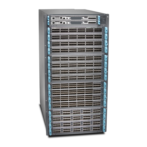
Juniper QFX10016 Hardware Manual (368 pages)
Brand:
Juniper
| Category:
Network Router
| Size: 26 MB
Table of Contents
Table of Contents
3
List of Tables
15
About the Documentation
19
Documentation and Release Notes
19
Supported Platforms
19
Documentation Conventions
19
Table 1: Notice Icons
20
Table 2: Text and Syntax Conventions
20
Documentation Feedback
21
About the Documentation
21
Requesting Technical Support
22
Self-Help Online Tools and Resources
22
Opening a Case with JTAC
22
Cooling System Components and Descriptions
25
Line Card Components and Descriptions
25
System Overview
25
Chassis Components and Descriptions
25
Control Board Components and Descriptions
25
Power System Components and Descriptions
25
Overview
25
Switch Fabric Components and Descriptions
25
Chapter 1 System Overview
27
System Overview
27
QFX10016 Hardware Overview
27
Table 3: QFX10016 Port Densities
27
Chassis Description
28
Figure 1: QFX10016 Chassis Front
29
System Overview
29
Figure 2: QFX10016 Chassis Rear
30
Control Board
31
Figure 3: QFX10016 Chassis Internal Components
31
Figure 4: QFX10000 Control Board
32
Line Cards
32
Figure 5: QFX10000-36Q Line Card
33
Figure 6: QFX10016 SIB
33
Sibs
33
Cooling System
34
Figure 7: QFX10016 Fan Tray
34
Figure 8: QFX10000 Fan Tray Controller
34
Power Supplies
34
Figure 10: QFX10000 DC Power Supply
35
Figure 9: QFX10000 AC Power Supply
35
Software
35
QFX10016 Components and Configurations
36
Table 4: QFX10016 Hardware Configurations
36
QFX10000 Component Redundancy
37
QFX10000 Hardware and CLI Terminology Mapping
38
Table 5: CLI Equivalents of Terms Used in Documentation for QFX10000
38
Chapter 2 Chassis Components and Descriptions
41
QFX10016 Chassis Physical Specifications
41
Table 6: QFX10016 Physical Specifications
41
Chassis Components and Descriptions
43
Figure 11: Front View of QFX100016
43
QFX10000 Field-Replaceable Units
44
Table 7: Frus in an QFX10000
44
QFX10000 Status Panel Leds
45
Figure 12: Status Panel
46
Table 8: Status Panel Leds in a QFX10000
46
QFX10000 Optional Equipment
47
QFX10000 Cable Management System
47
Card
47
Figure 13: QFX10000 Cable Management System
48
Figure 14: Cable Management Parts
48
Qfx10000 Sata Ssd
49
Figure 15: Two Cable Management Systems Installed on QFX10016
49
Figure 16: SATA SSD
49
Chapter 3 Control Board Components and Descriptions
51
QFX10000 Control Board Description
51
Control Board Functions
51
Figure 17: QFX10000 Control Board
51
Control Board Components
52
QFX10000 Control Board Leds
52
Figure 18: Control Board Faceplate
52
Control Board Status Panel Leds
53
Control Board Components and Descriptions
53
Figure 19: QFX10000 Control Board Leds
53
Figure 20: Control Board Status Panel Leds
53
Table 9: Control Board Status Leds
53
Figure 21: Management Port Leds on a QFX10000
54
QFX10000 Management Port Leds
54
SATA SSD Leds
55
Table 10: RJ-45 Management Port Leds on a QFX10000 Control Board
55
Table 11: SFP Management Port Leds on a QFX10000 Control Board
55
Table 12: Control Board Status Leds
55
Virtual Port Connections
56
Chapter 4 Cooling System Components and Descriptions
57
QFX10016 Cooling System and Airflow
57
Fan Tray
57
Figure 22: Fan Trays for a QFX10016
58
Table 13: QFX10016 Fan Tray Specifications
58
Fan Tray Controller
59
Cooling System Components and Descriptions
59
Airflow Direction in the QFX10016
60
Table 14: QFX100016 Fan Tray Controller Specifications
60
QFX10000 Fan Tray Leds and Fan Tray Controller Leds
61
Figure 23: Airflow through a QFX10016
61
Fan Tray Leds
62
Figure 24: Fan Tray Leds on a QFX10000
62
Table 15: Fan Tray Leds on a QFX10000
62
Fan Tray Controller Leds
65
Figure 25: Fan Tray Controller Leds on a QFX10000
65
Table 16: Fan Tray Controller Leds on a QFX100000
66
Chapter 5 Power System Components and Descriptions
67
QFX10000 AC Power Supply
67
AC Power Supply Description
67
Figure 26: AC Power Supply
69
Figure 27: Power Cord Retainer for an AC Power Supply
69
QFX10000 DC Power Supply
70
Figure 28: DC Power Supply
71
Figure 29: Leds on an AC Power Supply in QFX10000 Switches
72
QFX10000 AC Power Supply Leds
72
Table 17: Leds on an AC Power Supply in QFX10000
72
Figure 30: Leds on a DC Power Supply in QFX10000 Switches
73
QFX10000 DC Power Supply Leds
73
Table 18: Leds on an DC Power Supply in QFX10000
74
Power System Components and Descriptions
69
Chapter 6 Switch Fabric Components and Descriptions
75
QFX10016 Switch Interface Board Description
75
Figure 31: QFX10016 SIB
76
Table 19: Dimensions of a QFX10016 SIB
76
QFX10000 Switch Interface Board Leds
77
Figure 32: Sibs Installed in a QFX10016
77
Switch Fabric Components and Descriptions
77
Figure 33: SIB Leds
78
Table 20: SIB Leds
78
Chapter 7 Line Card Components and Descriptions
79
QFX10000-36Q Line Card
79
Overview
79
Switch Ports
80
Figure 34: QFX10000-36Q Port Panel
80
Figure 35: All Ports Are Enabled for 40-Gigabit Ethernet by Default
81
Figure 36: 100-Gigabit Ethernet Ports
81
Figure 37: 100-Gigabit Ethernet Port Disables Two Associated 40-Gigabit
81
Ethernet Ports
81
Line Card Components and Descriptions
81
Figure 38: Use the First and Fourth Port in each 6XQSFP Cage to Channelize a
82
Table 21: QFX10000-36Q Port Mapping
82
Status and Activity Leds
84
Figure 39: LED Indicators for QSFP+ and QSFP28 Ports
84
Table 22: Network Port Status and Activity Leds on a QFX10000-36Q Line
84
QFX10000-30C Line Card
85
Overview
85
Channelizing 40-Gigabit Ports
85
Figure 40: QFX10000-30C Port Panel
85
Figure 41: Disabled Ports in Channelization Mode
86
Table 23: Maximum Port Configuration
86
Table 24: Port Mapping for Channelization
86
Switch Ports
87
Status and Activity Leds
87
Figure 42: Indicators for QSFP28 Ports on QFX10000-30C Line Cards
87
QFX10000-60S-6Q Line Card
88
Table 25: Network Port Status and Activity Leds on a QFX10000-30C Line
88
Figure 43: QFX10000-60S-6Q Port Panel
89
Hardware Features
89
Port Groups
90
Channelization of 40-Gigabit Ethernet Ports
91
Figure 44: QFX10000-60S-6Q Port Groups
91
Table 26: QFX10000-60S-6Q Port Mapping
91
Figure 45: Supported Placement for Copper and Fiber SFP+ Transceivers
92
Figure 46: Belly-To-Belly SFP Transceivers
92
SFP+ Status and Activity Leds
92
Using Copper and Fiber SFP Transceivers
92
Figure 47: SFP+ Port Indicators and Status Leds on a QFX10000-60S-6Q Line
93
Figure 48: LED Indicators on QSFP+ and QSFP28 Ports on QFX10000-60S-6Q
93
QSFP+ and QSFP28 Status and Activity Leds
93
Table 27: Network Port Status and Activity Leds for SFP+ Ports on a QFX10000-60S-6Q Line Card
93
QFX10K-12C-DWDM Coherent Line Card
94
Table 28: QSFP+ and QSFP28 Network Port Status and Activity Leds
94
Figure 49: QFX10K-12C-DWDM Port Panel
95
Hardware Features
95
Figure 50: QFX10K-12C-DWDM Interfaces
96
Compatibility
97
Optical Transmit Specifications
97
Table 29: QFX10K-12C-DWDM Modulation Formats
97
Table 30: Juniper Networks Compatible Products in 100 Gbps Mode
97
Table 31: QFX10K-12C-DWDM Optical Transmit Specifications
97
Optical Receive Specifications
98
Table 32: QFX10K-12C-DWDM Optical Receive Specifications
98
Figure 51: DWDM Port and Ethernet Link State Leds
99
Status and Activity Leds
99
Table 33: Network Port Status Leds (Ot Interfaces)
99
Table 34: Valid Et Interface Link Combinations of Every Two Ot Ports
99
Software Features
100
Table 35: Ethernet Link Leds (Et Interfaces)
100
Alarms, Errors, and Events
101
OT and ET Interface Alarms and Defects
107
Table 36: OT Interface Alarms and Defects
107
Table 37: ET Interface Alarms and Defects
108
QFX10000 Line Card Leds
109
Figure 52: Line Card Leds
109
1.2 Terabyte DWDM OTN Module Wavelengths
110
Table 38: Power and Status Leds
110
Table 39: QFX1000-12C-DWDM Module Wavelengths
110
Part 2 Site Planning, Preparation, and Specifications
127
Chapter 8 Preparation Overview
129
QFX10000 Environmental Requirements and Specifications
131
Table 41: QFX10000 Environmental Tolerances
131
General Site Guidelines
132
Site Electrical Wiring Guidelines
133
QFX10000 Rack Requirements
133
Table 42: Site Electrical Wiring Guidelines
133
Table 43: Rack Requirements for the QFX10000
134
QFX10000 Clearance Requirements for Airflow and Hardware Maintenance
135
Figure 53: Clearance Requirements for Airflow and Hardware Maintenance for
135
Figure 54: Clearance Requirements for Airflow and Hardware Maintenance for
136
Preparation Overview
129
QFX10000 Site Preparation Checklist
129
Table 40: Site Preparation Checklist
129
Chapter 9 Power Specifications and Requirements
137
Power Requirements for QFX10000 Components
137
Table 44: Power Requirements for QFX10000 Components
137
Calculating Power Requirements for a QFX10016 Switch
138
Calculating the Power Consumption of Your QFX10016 Configuration
139
Table 45: Chassis Power Consumption for Standard Configurations
139
Table 46: Line Card Power Consumption
139
Calculating the Number of Power Supplies Required for Your QFX10016
141
Configuration
141
Table 47: Total Power Available
141
Table 48: Total Power Available with Efficiency
142
QFX10000 AC Power Specifications
143
Table 49: Power Specifications for an AC Power Supply Used in a
143
Table 50: Physical Specifications for a QFX10000 AC Power Supply
143
QFX10000 Power Cord Specifications
144
Table 51: AC Power Cord Specifications for QFX10000 Modular Switches
145
QFX10000 DC Power Specifications
147
Table 52: Power Specifications for the QFX10000 DC Power Supply
147
QFX10000 Grounding Cable and Lug Specifications
148
Table 53: Physical Specifications of a QFX10000 DC Power Supply
148
Chapter 10 Transceiver and Cable Specifications
151
Determining QFX10000 Optical Transceiver and Cable Support
151
Cable Specifications for QSFP+ and QSFP28 Transceivers
152
Table 54: QSFP+ and QSFP28 Optical Module Receptacle Pinouts
152
QFX10000 Cable Specifications for Console and Management Connections
153
Table 55: QSFP+ MPO Fiber-Optic Crossover Cable Pinouts
153
Table 56: Cable Specifications for Console and Management Connections for
153
Dispersion
154
Signal Loss in Multimode and Single-Mode Fiber-Optic Cables
154
Attenuation and Dispersion in Fiber-Optic Cable
155
Calculating the Fiber-Optic Cable Power Budget for a QFX Series Device
155
Calculating the Fiber-Optic Cable Power Margin for a QFX Series Device
156
Table 57: Estimated Values for Factors Causing Link Loss
157
Chapter 11 Pinout Specifications
159
USB Port Specifications for the QFX Series
160
Management Port Connector Pinouts for the QFX Series
161
Table 59: RJ-45 Management Port Connector Pinouts for the QFX Series
161
Pinout Specifications
159
Console Port Connector Pinouts for a QFX10000
159
Table 58: Console Port Connector Pinouts for the QFX Series
159
Initial Installation and Configuration
163
Chapter 12 Unpacking and Mounting the Switch
165
QFX10016 Installation Overview
165
Unpacking the QFX10016
166
Figure 55: Shipping Crate and Accessory Box
167
Figure 56: Bracket Bolt Removal
168
Boards
169
Comparing the QFX10000 Order to the Packing List
170
Figure 57: Unpacking a Line Card
170
Table 60: Redundant Configuration Order
171
Table 61: Base Configuration Order
172
Table 62: QFX10000 Accessory Kit
173
Installing the Mounting Hardware for a QFX10000
174
Table 63: QFX10000 Rack-Mounting Kit
174
Table 64: QFX10000 Front Panel Kit
174
Figure 58: Mounting Brackets for Four-Post Rack Installation
176
Mounting a QFX10016 in a Four-Post Rack Using a Mechanical Lift
177
Figure 59: Loading the QFX10016 into a Rack Using a Mechanical Lift
178
Figure 60: Attaching Front-Mounting Brackets
179
Installing the Front Panel on a QFX10000
180
Figure 61: Front Panel Mounting Hardware
180
Figure 62: Attaching Front Panel Brackets on a QFX10008
181
Figure 63: Attaching Front Panel Brackets on a QFX10016
182
Figure 64: Front Panel Installation on a QFX10008
183
Figure 65: Front Panel Installation on a QFX10016
184
Chapter 13 Connecting the Switch to Power
185
Connecting Earth Ground to a QFX10000
186
Figure 66: ESD Point for the QFX10008
187
Figure 67: ESD Point for the QFX10016
187
Figure 68: Connecting a Grounding Cable to the QFX10008
188
Figure 69: Connecting a Grounding Cable to the QFX10016
188
Connecting AC Power to a QFX10000
189
Connecting DC Power to a QFX10000
189
Chapter 14 Connecting the Switch to the Network
191
Connecting a Device to a Network for Out-Of-Band Management
191
Connecting a Device to a Management Console by Using an
191
Figure 70: RJ-45 Connector on an Ethernet Cable
191
Connector
192
Figure 71: Connecting a Device to a Network for Out-Of-Band Management
192
Figure 72: RJ-45 Connector on an Ethernet Cable
192
Figure 73: Connecting a Device to a Management Console through a Console
193
Figure 74: Connecting a Device Directly to a Management Console
193
Server
193
Chapter 15 Performing Initial Configuration
195
Configuring a QFX10000
195
Part 4 Installing, Maintaining, and Replacing Components
199
Chapter 16 Replacing Cooling System Components
201
Installing a QFX10000 Fan Tray
201
Figure 75: ESD Point for QFX10008 Chassis Rear
202
Figure 76: ESD Point for QFX10016 Chassis Rear
202
Figure 77: Installing a Fan Tray in a QFX10008
203
Removing a QFX10000 Fan Tray
204
Figure 78: Installing a Fan Tray in a QFX10016
204
Figure 79: ESD Point on QFX10008 Chassis Rear
206
Figure 80: ESD Point on QFX10016 Chassis Rear
206
Figure 81: Removing a Fan Tray from a QFX10008
207
Figure 82: Removing a Fan Tray from a QFX10016
208
Installing a QFX10000 Fan Tray Controller
209
Figure 83: Fan Tray Controller
209
Figure 84: Replacing a QFX10008 Fan Tray Controller
210
Figure 85: Replacing a QFX10016 Fan Tray Controller
210
Removing a QFX10000 Fan Tray Controller
211
Figure 86: Fan Tray Controller
211
Figure 87: Removing a QFX10008 Fan Tray Controller
212
Figure 88: Removing a QFX10016 Fan Tray Controller
212
Chapter 17 Replacing Power Supplies
213
Installing a QFX10000 AC Power Supply
213
Figure 89: ESD Point on QFX10008 Chassis Rear
214
Figure 90: ESD Point on QFX10016 Chassis Rear
214
Figure 91: Removing the PSU Cover Panel on a QFX10008
215
Figure 92: Removing the PSU Cover Panel on a QFX10016
215
Figure 93: Installing an AC Power Supply in a QFX10008
216
Figure 94: Installing an AC Power Supply in a QFX10016
217
Removing a QFX10000 AC Power Supply
218
Figure 95: Power Cord and Retainer Clip
218
Figure 96: ESD Point on QFX10008 Chassis Rear
220
Figure 97: ESD Point on QFX10016 Chassis Rear
220
Figure 98: Removing an AC Power Supply from a QFX10008
221
Installing a QFX10000 DC Power Supply
222
Figure 99: Removing an AC Power Supply from a QFX10016
222
Figure 100: ESD Point on QFX10008 Chassis Rear
224
Figure 101: ESD Point on QFX10016 Chassis Rear
224
Figure 102: Removing the Plastic Cable Cover on a QFX10000 DC Power
225
Supply
225
Figure 103: Connecting the DC Power Supply Cables to a QFX10000
227
Figure 104: Removing the PSU Cover Panel on a QFX10008
228
Figure 105: Removing the PSU Cover Panel on a QFX10016
228
Figure 106: Installing a DC Power Supply in a QFX10000
230
Removing a QFX10000 DC Power Supply
231
Figure 107: Setting the Enable Switches for the Power Source
231
Figure 108: ESD Point on Chassis Rear
233
Figure 109: ESD Point on QFX10016 Chassis Rear
233
Figure 110: Removing a DC Power Supply from a QFX10008
234
Figure 111: Removing a DC Power Supply from a QFX10016
235
Chapter 18 Replacing Switch Fabric Cards
237
Handling and Storing QFX10000 Line Cards, Control Boards, and Sibs
237
Holding Line Cards and Control Boards
237
Figure 112: Connector Edge of a Line Card
238
Holding Sibs
239
Figure 113: QFX10000 SIB
239
Storing Line Cards, Control Boards, and Sibs
240
Installing a QFX10000 Switch Interface Board
240
Figure 114: ESD Point on QFX10008 Chassis Rear
241
Figure 115: ESD Point on QFX10016 Chassis Rear
241
Figure 116: Removing a SIB Cover Plate on a QFX10008
242
Figure 117: Installing a QFX10008 SIB
243
Figure 118: Installing a QFX10016 SIB
244
Removing a QFX10000 Switch Interface Board
245
Figure 119: ESD Point on QFX10008 Chassis Rear
246
Figure 120: ESD Point on QFX10016 Chassis Rear
247
Figure 121: Loosening Captive Screws and Spread Ejector Handles
248
Figure 122: Removing the SIB from a QFX10008 Chassis
249
Figure 123: Removing the SIB from a QFX10016 Chassis
250
Figure 124: Extracted SIB
251
Chapter 19 Installing and Replacing Line Cards
253
Installing a QFX10000 Line Card
253
Figure 125: ESD Point on QFX10008 Chassis Front
254
Figure 126: ESD Point on QFX10016 Chassis Front
254
Figure 127: Removing the Cover Panel for a Line Card
254
Figure 128: Line Card Connectors
255
Figure 129: Inserting a Line Card into the Slot and Rotating the Handles
255
Removing a QFX10000 Line Card
256
Figure 130: ESD Point on QFX10008 Chassis Front
257
Figure 131: ESD Point on QFX10016 Chassis Front
257
Figure 132: Removing a QFX10000 Line Card
258
Installing the QFX10000 Cable Management System
259
Figure 133: QFX10000 Line Card Connectors
259
Figure 134: Cable Management System Components
260
Figure 135: Removing the Handle Screws
260
Figure 136: Adding Handle Extensions
261
Figure 137: Adding the Cable Tray
261
Figure 138: Completed Cable Management System
262
Chapter 20 Installing and Replacing a Control Board
263
Installing a QFX10000 Control Board
263
Figure 139: ESD Point for QFX10008 Chassis Front
264
Figure 140: ESD Point for QFX10016 Chassis Front
264
Figure 141: Removing a Control Board Cover Panel
264
Removing a QFX10000 Control Board
265
Figure 142: Control Board Installation
265
Figure 143: ESD Point on QFX10008 Chassis Front
266
Figure 144: ESD Point on QFX10016 Chassis Front
266
Figure 145: Removing a Control Board
267
Chapter 21 Installing and Replacing an SSD
269
Installing the Optional SATA Solid State Drive in a QFX10000
269
Figure 146: ESD Point on QFX10008 Chassis Front
270
Figure 147: ESD Point on QFX10016 Chassis Front
270
Figure 148: Removing the SATA SSD Cover Plate
270
Removing the Optional SATA Solid State Drive in a QFX10000
271
Figure 149: Installing the SATA SSD into the Slot
271
Figure 150: ESD Point on QFX10008 Chassis Front
272
Figure 151: ESD Point on QFX10016 Chassis Front
272
Figure 152: Removing the SATA SSD
272
Advertisement
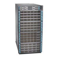
Juniper QFX10016 Hardware Manual (306 pages)
Brand:
Juniper
| Category:
Switch
| Size: 25 MB
Table of Contents
Table of Contents
3
List of Tables
15
About the Documentation
17
Documentation and Release Notes
17
Using the Examples in this Manual
17
Merging a Full Example
18
Merging a Snippet
18
About the Documentation
19
Documentation Conventions
19
Table 1: Notice Icons
19
Table 2: Text and Syntax Conventions
20
Documentation Feedback
21
Requesting Technical Support
21
Creating a Service Request with JTAC
22
Self-Help Online Tools and Resources
22
Card
23
Chapter 1 Overview
23
QFX10008 Hardware Overview
23
QFX10008 System Overview
23
Benefits of QFX10000 Modular Chassis Switches
24
Chassis Description
24
Figure 1: QFX10008 Chassis Front
25
Figure 2: QFX10008 Chassis Rear
26
Figure 3: QFX10008 Chassis Internal Components
27
Figure 4: QFX10000 RCB
27
Routing and Control Board
27
Ethernet Ports
28
Figure 5: QFX10000-36Q Line Card
28
Line Cards
28
Cooling System
29
Figure 6: QFX10008 SIB
29
Sibs
29
Figure 7: QFX10008 Fan Tray
30
Figure 8: QFX10000 Fan Tray Controller
30
Power Supplies
30
Figure 10: QFX10000 DC Power Supply
31
Figure 9: QFX10000 AC Power Supply
31
QFX10008 Configurations
31
Software
31
Table 3: QFX10008 Hardware Configurations
32
Card
33
QFX10000 Hardware and CLI Terminology Mapping
33
Table 4: CLI Equivalents of Terms Used in Documentation for QFX10000
33
QFX10000 Component Redundancy
34
QFX10000 Field-Replaceable Units
35
QFX10008 Chassis
35
Table 5: Frus in an QFX10000
35
QFX10000 Status Panel Leds
36
Figure 11: Status Panel
37
Figure 12: Status Panel on Chassis with the Enhanced Power Bus
37
Table 6: Status Panel Leds in a QFX10000
38
Figure 13: QFX10008 and QFX10016 EMI Front Panels
39
QFX10000 EMI Front Panel
39
Table 7: QFX10000 EMI Door Specifications
39
Figure 14: QFX10000 Cable Management System
40
Figure 15: Cable Management Parts
40
QFX10000 Cable Management System
40
QFX10000 Optional Equipment
40
Figure 16: Two Cable Management Systems Installed on QFX10016
41
Figure 17: SATA SSD
41
Qfx10000 Sata Ssd
41
Fan Tray
42
Figure 18: Fan Trays for a QFX10008
42
QFX10008 Cooling System
42
QFX10008 Cooling System and Airflow
42
Fan Tray Controller
43
Table 8: Fan Tray Specifications
43
Airflow Direction in the QFX10008
44
Table 9: Fan Tray Controller Specifications
44
Fan Tray Leds
45
Figure 19: Airflow through a QFX10008
45
QFX10000 Fan Tray Leds and Fan Tray Controller Leds
45
Figure 20: Fan Tray Leds on a QFX10000
46
Table 10: Fan Tray Leds on a QFX10000
46
Fan Tray Controller Leds
49
Figure 21: Fan Tray Controller Leds on a QFX10000
49
QFX10000 AC Power Supply
50
QFX10000 AC Power System
50
Table 11: Fan Tray Controller Leds on a QFX100000
50
AC Power Supply Description
51
Figure 22: AC Power Supply
52
Figure 23: Power Cord Retainer for an AC Power Supply
53
QFX10000 AC Power Specifications
53
Table 12: Power Specifications for an AC Power Supply Used in a QFX10000
53
Table 13: Physical Specifications for a QFX10000 AC Power Supply
53
QFX10000 Power Cord Specifications
54
Table 14: AC Power Cord Specifications for QFX10000 Modular Switches
55
QFX10000 AC Power Supply Leds
57
Figure 24: Leds on an AC Power Supply in QFX10000 Switches
58
Table 15: Leds on an AC Power Supply in QFX10000
58
QFX10000 DC Power Supply
59
QFX10000 DC Power System
59
Figure 25: DC Power Supply
60
QFX10000 DC Power Specifications
61
QFX10000 DC Power Supply Leds
61
Table 16: Power Specifications for the QFX10000 DC Power Supply
61
Table 17: Physical Specifications of a QFX10000 DC Power Supply
61
Figure 26: Leds on a DC Power Supply in QFX10000 Switches
62
Table 18: Leds on an DC Power Supply in QFX10000
62
Card
63
QFX10008 Switch Interface Board
63
QFX10008 Switch Interface Board Description
63
Table 19: Dimensions of a QFX10008 SIB
64
Figure 28: Sibs Installed in a QFX10008
65
QFX10000 Switch Interface Board Leds
65
Figure 29: SIB Leds
66
QFX10000 Routing and Control Board
66
Table 20: SIB Leds
66
Figure 30: QFX10000 Control Board
67
QFX10000 Routing and Control Board Description
67
Routing and Control Board Components
67
Routing and Control Board Functions
67
Figure 31: RCB Faceplate
68
Figure 32: QFX10000 RCB Leds
68
QFX10000 Routing and Control Board Leds
68
RCB Status Panel Leds
68
Figure 33: RCB Status Panel Leds
69
QFX10000 Management Port Leds
69
Table 21: Control Board Status Leds
69
Figure 34: Management Port Leds on a QFX10000
70
SATA SSD Leds
70
Table 22: RJ-45 Management Port Leds on a QFX10000 RCB
70
Table 23: SFP Management Port Leds on a QFX10000 RCB
70
QFX10000 Line Cards
71
QFX10000-30C Line Card
71
Table 24: Control Board Status Leds
71
Virtual Port Connections
71
Channelizing 40-Gigabit Ports
72
Figure 35: QFX10000-30C Port Panel
72
Figure 36: Disabled Ports in Channelization Mode
72
Overview
72
Table 25: Maximum Port Configuration
72
Switch Ports
73
Table 26: Port Mapping for Channelization
73
Figure 37: Indicators for QSFP28 Ports on QFX10000-30C Line Cards
74
Status and Activity Leds
74
Table 27: Network Port Status and Activity Leds on a QFX10000-30C Line
74
Overview
75
QFX10000-30C-M Line Card
75
Channelizing 40-Gigabit Ports
76
Figure 38: QFX10000-30C-M Port Panel
76
Figure 39: Disabled Ports in Channelization Mode
76
Table 28: Maximum Port Configuration
76
Network Ports
77
Power and Status Leds
77
Table 29: Port Mapping for Channelization
77
Table 30: Power LED
77
Figure 40: Indicators for QSFP28 Ports on QFX10000-30C-M Line Cards
78
Offline Button
78
Port Status and Activity Leds
78
Table 31: Status LED
78
Overview
79
QFX10000-36Q Line Card
79
Table 32: Network Port Status and Activity Leds on a QFX10000-30C-M Line
79
Figure 41: QFX10000-36Q Port Panel
80
Switch Ports
80
Figure 42: All Ports Are Enabled for 40-Gigabit Ethernet by Default
81
Figure 43: 100-Gigabit Ethernet Ports
81
Figure 44: 100-Gigabit Ethernet Port Disables Two Associated 40-Gigabit
81
Figure 45: Use the First and Fourth Port in each 6XQSFP Cage to Channelize a
82
Table 33: QFX10000-36Q Port Mapping
82
Figure 46: LED Indicators for QSFP+ and QSFP28 Ports
84
Status and Activity Leds
84
Table 34: Network Port Status and Activity Leds on a QFX10000-36Q Line
84
Hardware Features
85
QFX10000-60S-6Q Line Card
85
Figure 47: QFX10000-60S-6Q Port Panel
86
Channelization of 40-Gigabit Ethernet Ports
87
Figure 48: QFX10000-60S-6Q Port Groups
87
Port Groups
87
Table 35: QFX10000-60S-6Q Port Mapping
87
Figure 49: Supported Placement for Copper and Fiber SFP+ Transceivers
88
Using Copper and Fiber SFP Transceivers
88
Figure 50: Belly-To-Belly SFP Transceivers
89
Figure 51: SFP+ Port Indicators and Status Leds on a QFX10000-60S-6Q Line
89
SFP+ Status and Activity Leds
89
Table 36: Network Port Status and Activity Leds for SFP+ Ports on a QFX10000-60S-6Q Line Card
89
Figure 52: LED Indicators on QSFP+ and QSFP28 Ports on QFX10000-60S-6Q
90
QFX10K-12C-DWDM Coherent Line Card
90
QSFP+ and QSFP28 Status and Activity Leds
90
Table 37: QSFP+ and QSFP28 Network Port Status and Activity Leds
90
Figure 53: QFX10000-6C-DWDM Port Panel
91
Hardware Features
91
Figure 54: QFX10K-12C-DWDM Interfaces
92
Table 38: QFX10000-6C-DWDM Modulation
92
Compatibility
93
Optical Transmit Specifications
93
Table 39: Juniper Networks Compatible Products in 100 Gbps Mode
93
Table 40: QFX10000-6C-DWDM Optical Transmit Specifications
93
Optical Receive Specifications
94
Table 41: QFX10K-12C-DWDM Optical Receive Specifications
94
Figure 55: DWDM Port and Ethernet Link State Leds
95
Status and Activity Leds
95
Table 42: Network Port Status Leds (OT Interfaces)
95
Table 43: Valid et Interface Link Combinations
95
1.2 Terabyte DWDM OTN Module Wavelengths
96
Table 44: Ethernet Link Leds (et Interfaces)
96
Table 45: DWDM Module Wavelengths
96
Figure 56: Line Card Leds
112
QFX10000 Line Card Leds
112
Table 46: Power and Status Leds
113
Chapter 2 Site Planning, Preparation, and Specifications
115
QFX10000 Site Preparation Checklist
115
Table 47: Site Preparation Checklist
115
Qfx10000 Environmental Requirements and Specifications
117
QFX10008 Site Guidelines and Requirements
117
Table 48: QFX10000 Environmental Tolerances
117
General Site Guidelines
118
QFX10008 Installation Overview
118
QFX10016 Installation Overview
118
QFX10000 Rack Requirements
119
QFX5120 Site Electrical Wiring Guidelines
119
Table 49: Site Electrical Wiring Guidelines
119
Table
120
Table 50: Rack Requirements for the QFX10000
120
Figure 57: Clearance Requirements for Airflow and Hardware Maintenance for
121
Figure 58: Clearance Requirements for Airflow and Hardware Maintenance for a QFX10016 Modular Chassis
121
Maintenance
121
QFX10008 Chassis Physical Specifications
122
Table 51: QFX10008 Physical Specifications
122
Figure 59: Front View of QFX10008
123
Power Requirements for QFX10000 Components
124
QFX10008 Power Planning
124
Table 52: Power Requirements for QFX10000 Components
124
Calculating Power Requirements for a QFX10008
125
Calculating the Number of Power Supplies Required for Your QFX10008
126
Calculating the Power Consumption of Your QFX10008
126
Configuration
126
Table 53: Chassis Power Consumption for Standard Configurations
126
Table 54: Line Card Power Consumption
126
Configuration
127
QFX10000 Grounding Cable and Lug Specifications
128
Table 55: Total Power Available
128
Cable Specifications for QSFP+ and QSFP28 Transceivers
130
QFX10000 Optical Transceiver and Cable Support
130
QFX10000 Transceiver and Cable Specifications
130
Understanding QFX Series Fiber-Optic Cable Signal Loss, Attenuation, and Dispersion
130
Table 56: QSFP+ and QSFP28 Optical Module Receptacle Pinouts
131
Table 57: QSFP+ MPO Fiber-Optic Crossover Cable Pinouts
131
Signal Loss in Multimode and Single-Mode Fiber-Optic Cables
132
Attenuation and Dispersion in Fiber-Optic Cable
133
Calculating Power Budget and Power Margin for Fiber-Optic Cables
133
Calculating Power Budget for Fiber-Optic Cable
134
Calculating Power Margin for Fiber-Optic Cable
134
Table 58: Estimated Values for Factors Causing Link Loss
134
QFX10000 Cable Specifications for Console and Management
135
QFX10000 Console and Management Cable Specifications and Pinouts
135
Connections
136
RJ-45 to DB-9 Serial Port Adapter Pinout Information
136
Table 59: Cable Specifications for Console and Management Connections for
136
Table 60: RJ-45 to DB-9 Serial Port Adapter Pinout Information
136
Console Port Connector Pinout Information
137
RJ-45 Management Port Connector Pinout Information
137
Table 61: RJ-45 Management Port Connector Pinout Information
137
Table 62: Console Port Connector Pinout Information
138
USB Port Specifications for the QFX Series
138
Chapter 3 Initial Installation and Configuration
141
QFX10008 Installation Overview
141
Unpacking the QFX10008
142
Unpacking the Chassis
142
Figure 60: Shipping Crate and Accessory Box
143
Unpacking QFX10000 Line Cards, Routing and Control Boards, and Switch Interface Boards
144
Figure 61: Bracket Bolt Removal
144
Figure 62: Unpacking a Line Card
145
Comparing the QFX10000 Order to the Packing List
146
Table 63: Redundant Configuration Order
146
Table 64: Base Configuration Order
147
Table 65: QFX10000 Accessory Kit
148
Table 66: QFX10000 Rack Mount Kit
149
Table 67: QFX10000 Front Panel Kit
149
Installing the Mounting Hardware for a QFX10000
150
Figure 63: Mounting Brackets for Four-Post Rack Installation
151
Installing the QFX10008 into a Rack
152
Mounting a QFX10008 in a 4-Post Rack Using a Mechanical Lift
152
Figure 64: Loading the QFX10008 into a Rack Using a Mechanical Lift
154
Manually Mounting a QFX10008 in a 4-Post Rack
155
Figure 65: Attaching Front-Mounting Brackets
155
Figure 66: Lifting the QFX10008 Without Using a Mechanical Lift
157
Figure 67: Installing a QFX10008 in a 4-Post Rack
158
Installing the Front Panel on a QFX10000
159
Figure 68: Front Panel Mounting Hardware
159
Figure 69: Attaching Front Panel Brackets on a QFX10008
160
Figure 70: Attaching Front Panel Brackets on a QFX10016
161
Figure 71: Front Panel Installation on a QFX10008
162
Connecting the QFX10000 to Power
163
Figure 72: Front Panel Installation on a QFX10016
163
Connecting Earth Ground to a QFX10000
164
Figure 73: ESD Point for the QFX10008
165
Figure 74: ESD Point for the QFX10016
165
Figure 75: Connecting a Grounding Cable to the QFX10008
166
Figure 76: Connecting a Grounding Cable to the QFX10016
166
Connecting AC Power to a QFX10000
167
Connecting DC Power to a QFX10000
167
Connecting the QFX10000 to External Devices
168
Connecting a Device to a Network for Out-Of-Band Management
168
Connecting a Device to a Management Console by Using an
168
Figure 77: RJ-45 Connector on an Ethernet Cable
168
Connector
169
Figure 78: Connecting a Device to a Network for Out-Of-Band Management
169
Figure 79: RJ-45 Connector on an Ethernet Cable
169
Configuring a QFX10000
170
Figure 80: Connecting a Device to a Management Console through a Console
170
Figure 81: Connecting a Device Directly to a Management Console
170
Chapter 4 Maintaining Components
173
Handling and Storing QFX10000 Line Cards, Rcbs, and Sibs
173
Holding Line Cards and Rcbs
173
Figure 82: Connector Edge of a Line Card
174
Holding Sibs
175
Figure 83: QFX10000 SIB
175
Storing Line Cards, Rcbs, and Sibs
176
Maintaining QFX10000 Routing and Control Boards
176
Removing a QFX10000 Routing and Control Board
177
Figure 84: ESD Point on QFX10008 Chassis Front
177
Figure 85: ESD Point on QFX10016 Chassis Front
177
Installing a QFX10000 Routing and Control Board
178
Figure 86: Removing an RCB
178
Figure 87: ESD Point for QFX10008 Chassis Front
179
Figure 88: ESD Point for QFX10016 Chassis Front
179
Figure 89: Removing a RCB Cover Panel
179
Maintaining QFX10008 Cooling System
180
Figure 90: RCB Installation
180
Removing a QFX10008 Fan Tray
181
Figure 91: ESD Point on QFX10008 Chassis Rear
181
Installing a QFX10008 Fan Tray
182
Figure 92: Removing a Fan Tray from a QFX10008 Chassis
182
Figure 93: ESD Point for QFX10008 Chassis Rear
183
Removing a QFX10008 Fan Tray Controller
184
Figure 94: Installing a Fan Tray in a QFX10008 Chassis
184
Figure 95: QFX10008 Fan Tray Controller
184
Installing a QFX10008 Fan Tray Controller
185
Figure 96: Removing a QFX10008 Fan Tray Controller
185
Figure 97: Fan Tray Controller
186
Maintaining QFX10000 Power System
187
Removing a QFX10000 AC Power Supply
187
Figure 98: Replacing a QFX10008 Fan Tray Controller
187
Figure 99: ESD Point on QFX10008 Chassis Rear
189
Figure 100: ESD Point on QFX10016 Chassis Rear
189
Figure 101: Removing an AC Power Supply from a QFX10008
190
Installing a QFX10000 AC Power Supply
191
Figure 102: Removing an AC Power Supply from a QFX10016
191
Figure 103: ESD Point on QFX10008 Chassis Rear
192
Figure 104: ESD Point on QFX10016 Chassis Rear
192
Figure 105: Removing the PSU Cover on a QFX10008
193
Figure 106: Removing the PSU Cover on a QFX10016
193
Figure 107: Installing an AC Power Supply in a QFX10008
194
Figure 108: Installing an AC Power Supply in a QFX10016
195
Removing a QFX10000 DC Power Supply
196
Figure 109: Power Cord and Retainer Clip
196
Figure 110: ESD Point on Chassis Rear
198
Figure 111: ESD Point on QFX10016 Chassis Rear
198
Figure 112: Removing a DC Power Supply from a QFX10008
199
Installing a QFX10000 DC Power Supply
200
Figure 113: Removing a DC Power Supply from a QFX10016
200
Figure 114: ESD Point on QFX10008 Chassis Rear
202
Figure 115: ESD Point on QFX10016 Chassis Rear
202
Figure 116: Removing the Plastic Cable Cover on a QFX10000 DC Power
203
Figure 117: Connecting the DC Power Supply Cables to a QFX10000
205
Figure 118: Removing the PSU Cover on a QFX10008
206
Figure 119: Removing the PSU Cover on a QFX10016
206
Figure 120: Installing a DC Power Supply in a QFX10000
208
Maintaining QFX10000 Switch Interface Boards
209
Removing a QFX10000 Switch Interface Board
209
Figure 27: SIB
209
Figure 121: Setting the Enable Switches for the Power Source
209
Figure 122: ESD Point on QFX10008 Chassis Rear
210
Figure 123: ESD Point on QFX10016 Chassis Rear
211
Figure 124: Loosening Captive Screws and Spread Ejector Handles
212
Figure 125: Removing the SIB from a QFX10008 Chassis
213
Figure 126: Removing the SIB from a QFX10016 Chassis
214
Installing a QFX10000 Switch Interface Board
215
Figure 127: Extracted SIB
215
Figure 128: ESD Point on QFX10008 Chassis Rear
216
Figure 129: ESD Point on QFX10016 Chassis Rear
216
Figure 130: Removing a SIB Cover Plate on a QFX10008
217
Figure 131: Installing a QFX10008 SIB
218
Figure 132: Installing a QFX10016 SIB
219
Maintaining QFX10000 Line Cards
221
Removing a QFX10000 Line Card
221
Figure 133: ESD Point on QFX10008 Chassis Front
222
Figure 134: ESD Point on QFX10016 Chassis Front
222
Figure 135: Removing a QFX10000 Line Card
223
Installing a QFX10000 Line Card
224
Figure 136: QFX10000 Line Card Connectors
224
Figure 137: ESD Point on QFX10008 Chassis Front
225
Figure 138: ESD Point on QFX10016 Chassis Front
225
Figure 139: Removing the Cover for a Line Card
225
Figure 140: Line Card Connectors
226
Figure 141: Inserting a Line Card into the Slot and Rotating the Handles
226
Installing the QFX10000 Cable Management System
227
Figure 142: Cable Management System Components
227
Figure 143: Removing the Handle Screws
228
Figure 144: Adding Handle Extensions
228
Figure 145: Adding the Cable Tray
229
Figure 146: Completed Cable Management System
229
Maintaining QFX10000 Solid State Drives
230
Removing the Optional SATA Solid State Drive in a QFX10000
230
Figure 147: ESD Point on QFX10008 Chassis Front
231
Figure 148: ESD Point on QFX10016 Chassis Front
231
Figure 149: Removing the SATA SSD
231
Installing the Optional SATA Solid State Drive in a QFX10000
232
Figure 150: ESD Point on QFX10008 Chassis Front
233
Figure 151: ESD Point on QFX10016 Chassis Front
233
Figure 152: Removing the SATA SSD Cover
233
Maintaining Transceivers and Fiber-Optic Cables on QFX10000
234
Removing a Transceiver
234
Figure 153: Installing the SATA SSD into the Slot
234
Figure 154: Removing an SFP, SFP+, XFP, or a QSFP+ Transceiver
236
Installing a Transceiver
237
Disconnecting a Fiber-Optic Cable
239
Figure 155: Installing a Transceiver
239
Connecting a Fiber-Optic Cable
240
Maintaining Fiber-Optic Cables
240
Figure 156: Connecting a Fiber-Optic Cable to an Optical Transceiver Installed
240
Removing the QFX10008
241
Powering off a QFX10000
241
Removing a QFX10008 from a 4-Post Rack Using a Mechanical Lift
243
Manually Removing a QFX10008 from a 4-Post Rack
245
Figure 157: Moving the QFX10008 Using a Mechanical Lift
245
Figure 158: Lifting the QFX10008 Without Using a Mechanical Lift
247
Chapter 5 Troubleshooting
249
Troubleshooting QFX10000 Modular Chassis
249
QFX10000 Troubleshooting Resources Overview
249
Chassis Alarm Messages on QFX10008 and QFX10016 Modular Chassis
249
Switches
249
QFX Series Alarm Messages Overview
250
Table 68: Chassis Component Alarm Conditions on QFX10000 Modular
251
Chapter 6 Contacting Customer Support and Returning the Chassis or
255
Components
255
Contacting Customer Support to Obtain Return Material Authorization
255
Returning the QFX10000 Chassis or Component
256
Returning a Hardware Component to Juniper Networks, Inc
256
Locating the Serial Number on a QFX10000 Switch or Component
257
Listing the Chassis and Component Details Using the CLI
257
Qfx10016
259
Figure 159: QFX10008 Serial Number Label
259
Locating the Serial Number ID Labels on QFX10000 Power
260
Supplies
260
Figure 160: QFX10016 Serial Number Label
260
Locating the Serial Number ID Labels on QFX10000 Fan Trays and Fan Tray Controllers
261
Figure 161: QFX10000 AC Power Supply Serial Number Location
261
Figure 162: QFX10000 DC Power Supply Serial Number Location
261
Locating the Serial Number ID Labels on QFX10000 Control Boards
262
Figure 163: QFX10000 Fan Tray Serial Number Location
262
Figure 164: QFX10000 Fan Tray Controller Serial Number Location
262
Locating the Serial Number ID Labels on a QFX10000 Line Card
263
Locating the Serial Number ID Labels on a QFX10000 Switch Interface
263
Board (SIB)
263
Figure 165: QFX10000 Control Board Serial Number Location
263
Figure 166: QFX10000 Line Card Serial Number Location
263
Locating the Serial Number ID Label on a QFX10000 SATA SSD
264
Packing a QFX10000 or Component for Shipping
264
Figure 167: QFX10000 SIB Serial Number Location
264
Figure 168: QFX10000 SATA SSD Serial Number Location
264
Packing a QFX10000 Switch Chassis for Shipping
265
Figure 169: Stacking Configuration for Packing the QFX10008 Chassis
265
Packing QFX10000 Switch Components for Shipping
269
Chapter 7 Safety and Compliance Information
271
General Safety Guidelines and Warnings
272
Definitions of Safety Warning Levels
273
Qualified Personnel Warning
274
Warning Statement for Norway and Sweden
275
Fire Safety Requirements
275
Fire Suppression
275
Fire Suppression Equipment
275
Installation Instructions Warning
276
Chassis and Component Lifting Guidelines
277
Restricted Access Warning
277
Ramp Warning
278
Rack-Mounting and Cabinet-Mounting Warnings
279
Grounded Equipment Warning
283
Radiation from Open Port Apertures Warning
283
Laser and LED Safety Guidelines and Warnings for the QFX Series
284
Class 1M Laser Product Warning
285
Class 1M Laser Radiation Warning
285
Unterminated Fiber-Optic Cable Warning
285
Maintenance and Operational Safety Guidelines and Warnings
287
Battery Handling Warning
287
Jewelry Removal Warning
288
Lightning Activity Warning
289
Operating Temperature Warning
290
Product Disposal Warning
291
General Electrical Safety Guidelines and Warnings
292
Action to Take after an Electrical Accident
293
Prevention of Electrostatic Discharge Damage
293
AC Power Electrical Safety Guidelines
294
AC Power Disconnection Warning
295
DC Power Electrical Safety Guidelines
296
DC Power Disconnection Warning
296
DC Power Grounding Requirements and Warning
298
DC Power Wiring Terminations Warning
299
Multiple Power Supplies Disconnection Warning
300
TN Power Warning
301
Agency Approvals for the QFX Series
301
Compliance Statements for EMC Requirements for the QFX Series
302
Canada
303
European Community
303
Israel
303
Japan
304
Korea
304
Tawain
304
United States
305
Nonregulatory Environmental Standards
305
QFX Series Compliance Statements for NEBS
306
Compliance Statements for Environmental Requirements
306
Juniper QFX10016 Hardware Manual (439 pages)
Brand:
Juniper
| Category:
Switch
| Size: 33 MB
Table of Contents
Table of Contents
3
About this Guide
11
Overview
12
Qfx10016 System Overview/Qfx10016 Hardware Overview
13
QFX10016 Hardware Overview
13
QFX10016 System Overview
13
Chassis Description
17
Line Cards
21
Routing and Control Board
21
Switch Interface Boards
22
Cooling System
23
Power Supplies
25
Software
28
QFX10016 Components and Configurations
29
QFX10000 Hardware and CLI Terminology Mapping
31
QFX10000 Component Redundancy
33
In this Section
35
QFX10000 Chassis
35
QFX10000 Field-Replaceable Units
35
QFX10000 Status Panel
37
QFX10000 EMI Front Panel
40
QFX10000 Optional Equipment
41
QFX10016 Cooling System
44
QFX10016 Cooling System and Airflow
44
QFX10000 Fan Tray Leds and Fan Tray Controller Leds
50
Qfx10000-Pwr-Ac Power Supply
57
In this Section
57
QFX10000 AC Power System
57
QFX10000-PWR-AC Power Specifications
60
JNP10K-PWR-AC2 Power Supply
61
JNP10K-PWR-AC2 Power Specifications
63
QFX10000 Power Cables Specifications
64
QFX10000 AC Power Supply Leds
75
JNP10K-PWR-AC2 Power Supply Leds
77
QFX10000 DC Power System
79
QFX10000-PWR-AC Power Supply
80
Qfx10000 Line Cards
104
QFX10000-30C Line Card
104
Channelizing 40-Gigabit Ports
105
Overview
105
Switch Ports
107
Status and Activity Leds
108
In this Section
109
QFX10000-30C-M Line Card
109
In this Section
115
QFX10000-36Q Line Card
115
Qfx10000-60S-6Q Line Card
123
Hardware Features
124
Port Groups
125
Channelization of 40-Gigabit Ethernet Ports
126
Using Copper and Fiber SFP Transceivers
127
SFP+ Status and Activity Leds
128
QSFP+ and QSFP28 Status and Activity Leds
129
QFX10K-12C-DWDM Coherent Line Card
130
Terabyte Per Second DWDM OTN Module Wavelengths
137
QFX10000 Line Card Leds
163
Offline Button
164
Maintaining Components
240
QFX10000 Field-Replaceable Units
241
Handling and Storing QFX10000 Line Cards, Rcbs, and Sibs
243
Maintaining QFX10000 Routing and Control Boards
247
Maintaining QFX10016 Cooling System Components
252
Installing a QFX10016 Fan Tray Controller
260
Advertisement
Juniper QFX10016 Quick Start Manual (31 pages)
Brand:
Juniper
| Category:
Switch
| Size: 7 MB
Table of Contents
Table of Contents
1
Quick Start Description
2
Step 1-Preparing the Site for the QFX10016
2
Rack-Mounting Requirements
2
Clearance Requirements
3
Cooling and Airflow Requirements
3
Step 2-Unpacking the QFX10016
4
Step 3-Mounting the Switch Chassis
7
Installing the Mounting Hardware
7
Mounting the QFX10016 Using a Mechanical Lift
9
Step 4-Installing Line Cards
12
Step 5-Installing the Front Panel
15
Step 6-Connecting Power to the Chassis
17
Ground the Chassis
17
Install AC Power Supplies
20
Install DC Power Supplies
23
Step 7-Connecting to the Network
28
Step 8-Performing Initial Configuration
28
Safety Warnings Summary
30
Power Cable Warning (Japanese)
31
Juniper QFX10016 Quick Start Manual (24 pages)
Brand:
Juniper
| Category:
Network Hardware
| Size: 5 MB
Table of Contents
Table of Contents
1
Step 1: Begin
1
Meet the QFX10016
2
Prepare the Site for the QFX10016
2
Unpack the QFX10016
4
Mount the Switch Chassis
5
Install the QFX10016
7
Install the Line Cards
10
Install the Front Panel
11
Connect Power to the Chassis
13
Step 2: up and Running
19
Step 3: Keep Going
22
Advertisement
Related Products
Juniper QFX10002
Juniper QFX5100
Juniper QFX5100-48SH
Juniper QFX5100-48TH
Juniper QFX10002-36Q
Juniper QFX10002-72Q
Juniper QFX10008
Juniper QFX10002-60C
Juniper QFX5100-32Q
Juniper 6rd
Juniper Categories
Network Router
Switch
Gateway
Software
Network Hardware
More Juniper Manuals
Login
Sign In
OR
Sign in with Facebook
Sign in with Google
Upload manual
Upload from disk
Upload from URL