Juniper QFX10016 Hardware Manual
Hide thumbs
Also See for QFX10016:
- Hardware manual (368 pages) ,
- Quick start manual (31 pages) ,
- Quick start manual (24 pages)
Table of Contents
Advertisement
Quick Links
Advertisement
Chapters
Table of Contents

Related Manuals for Juniper QFX10016


Summary of Contents for Juniper QFX10016
- Page 1 QFX10016 Switch Hardware Guide Published 2022-09-09...
- Page 2 The Juniper Networks product that is the subject of this technical documentation consists of (or is intended for use with) Juniper Networks software. Use of such software is subject to the terms and conditions of the End User License Agreement ("EULA") posted at https:/ /support.juniper.net/support/eula/.
-
Page 3: Table Of Contents
QFX10000 EMI Front Panel | 29 QFX10000 Optional Equipment | 30 QFX10016 Cooling System | 33 QFX10016 Cooling System and Airflow | 33 QFX10000 Fan Tray LEDs and Fan Tray Controller LEDs | 39 QFX10000 AC Power System | 46... - Page 4 QFX10000-PWR-DC Power Supply LEDs | 77 JNP10K-PWR-DC2 Power Supply LEDs | 79 QFX10016 Switch Interface Board | 81 QFX10016 Switch Interface Board Description | 81 QFX10000 Switch Interface Board LEDs | 85 QFX10000 Routing and Control Board | 86 QFX10000 Routing and Control Board Description | 86...
- Page 5 Calculating Power Requirements for a QFX10016 | 172 How to Calculate the Power Consumption of Your QFX10016 | 173 How to Calculate the Number of Power Supplies Required for Your QFX10016 Configuration | 176 QFX10008 and QFX100016 Grounding Cable and Lug Specifications | 178...
- Page 6 Register Products—Mandatory to Validate SLAs | 204 Installing the Mounting Hardware for a QFX10000 | 205 Mounting a QFX10016 in a Four-Post Rack Using a Mechanical Lift | 207 Installing the Front Panel on a QFX10000 | 211 Connecting the QFX10008 or QFX10016 to Power | 217...
- Page 7 Removing a QFX10016 Fan Tray Controller | 247 Installing a QFX10016 Fan Tray Controller | 249 Maintaining QFX10000 Power System | 252 How to Remove a QFX10000-PWR-AC Power Supply | 252 How to Install a QFX10000-PWR-AC Power Supply | 257...
- Page 8 Locating the Serial Number on a QFX10000 Switch or Component | 365 Listing the Chassis and Component Details Using the CLI | 366 Locating the Chassis Serial Number ID Label on a QFX10008 or QFX10016 | 368 Locating the Serial Number ID Labels on QFX10000 Power Supplies | 369...
- Page 9 Warning Statement for Norway and Sweden | 389 Fire Safety Requirements | 390 Installation Instructions Warning | 391 QFX10016 Chassis Lifting Guidelines | 392 Restricted Access Warning | 392 Ramp Warning | 394 Rack-Mounting and Cabinet-Mounting Warnings | 394 Grounded Equipment Warning | 398...
- Page 10 Compliance Statements for Environmental Requirements | 428...
-
Page 11: About This Guide
About This Guide Use this guide to plan, install, perform initial software configuration, perform routine maintenance, and to troubleshoot QFX10016 modular switches. After completing the installation and basic configuration procedures covered in this guide, refer to the Junos OS documentation for further software configuration. -
Page 12: Overview
QFX10016 System Overview | 2 QFX10000 Chassis | 24 QFX10016 Cooling System | 33 QFX10000 AC Power System | 46 QFX10000 DC Power System | 68 QFX10016 Switch Interface Board | 81 QFX10000 Routing and Control Board | 86 QFX10000 Line Cards | 93... -
Page 13: Qfx10016 System Overview
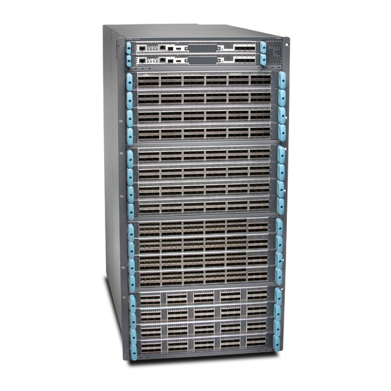
QFX10000 line of switches, the QFX10016 can provide 96 Tbps of throughput and 32 Bpps of forwarding capacity in a 21 rack unit (21 U) chassis. The QFX10016 has 16 slots for line cards that allow for a smooth transition from 10-Gigabit Ethernet and 40-Gigabit Ethernet networks to 100-Gigabit Ethernet high-performance networks. - Page 14 • Juniper Networks MC-LAG for Layer 2 and 3 networks The QFX10016 is available in both base and redundant configurations for both AC and DC operation. All systems feature front-to-back airflow. This airflow is also know as airflow out (AFO).
- Page 15 Figure 1 on page 5 shows a front and rear view of the QFX10016.
- Page 16 Figure 1: QFX10016—Front and Rear...
-
Page 17: Chassis Description
Chassis Description The QFX10016 is 21 U tall. Two QFX10016 chassis can fit in a standard 42 U rack with adequate cooling and power. All key QFX10016 components are field-replaceable units (FRUs). Figure 2 on page illustrates the key components visible from the front and rear of the chassis.,... - Page 18 Figure 4 on page 9 illustrates the components that are internal to the chassis. Figure 2: QFX10016 Chassis Front RCBs slots 0 and 1 (numbered top to bottom) Installation holes for the front panel —...
- Page 19 Some chassis ship with an enhanced power bus to support the power needs of higher wattage line QFX10000 Status Panel cards. Chassis with the enhanced power bus have a modified Status Panel (see Figure 3: QFX10016 Chassis Rear AC or DC power supplies slots 0 to 9 ESD point —...
- Page 20 Figure 4: QFX10016 Chassis Internal Components Fan tray controllers slots 0 and 1 (numbered Switch Interface Boards (SIBs) slots 0 to 5 — — left to right) (numbered left to right) "QFX10016 Chassis Physical Specifications" on page 166 "QFX10000 Field-Replaceable Units" on page...
-
Page 21: Routing And Control Board
Figure 5: QFX10000 Routing and Control Board (QFX10000-RE) Line Cards The QFX10016 features 16 horizontal line card slots and supports line rate for each line card. The line cards combine a Packet Forwarding Engine (PFE) and Ethernet interfaces enclosed in a single assembly. -
Page 22: Switch Interface Boards
QFX10016. A sixth SIB is available in the redundant configuration to provide installed between the line cards and the fan trays inside of the chassis (see Figure 7 on page 12). Each QFX10016 SIB has 16 connectors that match to a line card slot, eliminating the need for a backplane. -
Page 23: Cooling System
When all six SIBs are installed, the QFX10016 has a net switching capacity of 96 Tbps. See "QFX10016 Switch Interface Board Description" on page Figure 7: QFX10016 SIB Cooling System The cooling system in a QFX10016 consists of two hot-removable and hot-insertable FRU fan trays (see... - Page 24 The fan trays install vertically on the rear of the chassis and provide front-to-back chassis cooling. "QFX10016 Cooling System and Airflow " on page Figure 8: Fan Tray (QFX10016-FAN) Figure 9: Fan Tray Controller (QFX10016-FAN-CTRL)
-
Page 25: Power Supplies
All of the power supplies for the QFX10000 are fully redundant, load-sharing, and hot-removable and hot-insertable FRUs. Each QFX10016 base configuration has five power supplies; redundant configurations hold the maximum of ten AC HVAC, DC, or HVDC power supplies. Each power supply has an internal fan for cooling. - Page 26 (Continued) Table 2: Power Supply Overview QFX10000-PWR- JNP10K-PWR-AC2 QFX10000-PWR- JNP10K-PWR-DC2 Note: *The JNP10K-PWR-AC2 and the JNP10K-PWR-DC2 power supplies are supported on both the standard and enhanced chassis. However, when these models are run in a standard chassis, the power management software sets the power budget to 3000 W.
- Page 27 CAUTION: Do not mix power supply models in the same chassis in a running environment. DC and HVDC can coexist in the same chassis during the hot swap of DC for HVDC. Figure 10: QFX10000-PWR-AC Power Supply Figure 11: JNP10K-PWR-AC2 Power Supply...
-
Page 28: Software
The same Junos OS code base that runs on QFX Series switches also runs on all Juniper Networks EX Series, M Series, MX Series, and T Series routers and SRX Series Services Gateways. The minimum Junos OS release is 15.1X53-D61. -
Page 29: Qfx10016 Components And Configurations
QFX10016 Components and Configurations Table 3 on page 18 lists the four hardware configurations for a QFX10016 modular chassis—base (AC version), and redundant (AC and DC versions)—and the components included in each configuration. Table 3: QFX10016 Hardware Configurations Switch Configuration... - Page 30 Two RCBs • Two QFX10016-FAN-CTRL fan tray controllers • Two QFX10016-FAN fan trays • Ten QFX10000-PWR-AC power supplies • Six QFX10016-SF Switch Interface Boards (SIBs) • Twenty power cords • Sixteen line card covers • One front panel Redundant DC configuration •...
-
Page 31: Qfx10000 Hardware And Cli Terminology Mapping
NOTE: If you want to purchase additional power supplies (AC or DC), SIBs, or RCBs for your switch configuration, you must order them separately. SEE ALSO QFX10016 Chassis Physical Specifications | 166 QFX10000 Hardware and CLI Terminology Mapping This topic describes the hardware terms used in QFX10000 documentation and the corresponding terms used in the Junos OS CLI. - Page 32 0–7 for the does not have actual Conventions Flexible PIC QFX10008 and 0–15 FPCs—the line cards Concentrator for the QFX10016. The are the FPC (FPC) value corresponds to equivalents on the the line card slot switch.) On QFX10008...
-
Page 33: Qfx10000 Component Redundancy
(Continued) Table 4: CLI Equivalents of Terms Used in Documentation for QFX10000 Switches Hardware Description (CLI) Value (CLI) Item In Documentation Additional Information Item (CLI) n is a value in the range show chassis fabric sibs SIB ( This field Fabric plane indicates: of 0–5. - Page 34 QFX10008 Cooling System and Airflow sufficient cooling for the switch indefinitely. See "QFX10016 Cooling System and Airflow " on page RELATED DOCUMENTATION QFX10016 Cooling System | 33...
-
Page 35: Qfx10000 Chassis
QFX10000 Chassis IN THIS SECTION QFX10000 Field-Replaceable Units | 24 QFX10000 Status Panel | 26 QFX10000 EMI Front Panel | 29 QFX10000 Optional Equipment | 30 QFX10000 Field-Replaceable Units Field-replaceable units (FRUs) are switch components that you can replace at your site. The switch uses these types of FRUs: •... - Page 36 QFX10008 Configurations and Upgrade Options "QFX10016 Components and Configurations" on page Switch Interface Boards (SIBs) SIBs are hot-insertable and hot-removable. We recommend that you take SIBs offline before removing them to avoid traffic loss while the switch fabric is being reconfigured.
-
Page 37: Qfx10000 Status Panel
NOTE: If you have a Juniper Care service contract, register any addition, change, or upgrade of hardware components at https:/ /www.juniper.net/customers/support/tools/updateinstallbase/. Failure to do so can result in significant delays if you need replacement parts. This note does not apply if you replace an existing component with the same type of component. - Page 38 Other chassis have the same set of five bi-color LEDs, but also have an azure blue line to indicate the enhanced power bus (see Figure 15 on page 27). Figure 15: Status Panel on Chassis with the Enhanced Power Bus Table 6 on page 27 describes the status panel LEDs.
- Page 39 (Continued) Table 6: Status Panel LEDs in a QFX10000 Name Color State Description None The fan tray controllers and fan trays are not receiving power. SIBs Green On steadily All installed Switch Interface Boards (SIBs) are online. Yellow On steadily There is an error in one or more SIBs.
-
Page 40: Qfx10000 Emi Front Panel
(EMI) protection. The panel attaches to the front of the chassis and swings open to allow easy access to optics and line cards, see Figure 16 on page 29 Table 7 on page Figure 16: QFX10008 and QFX10016 EMI Front Panels... -
Page 41: Qfx10000 Optional Equipment
Weight QFX10008 22.25 in. H x 17.70 in. W x 6.10 in. D 12.8 lb QFX10016 36.43 in. H x 17.70 in. W x 6.10 in. D 20.3 lb SEE ALSO Installing the Front Panel on a QFX10000 | 211... - Page 42 QFX10000 Cable Management System The QFX10000 cable management system (see Figure 17 on page 31) enables you to route optical cables away from the line card ports for better airflow through the chassis. Using this optional system also makes it easier to use cable ties or strips to organize the cabling. Figure 17: QFX10000 Cable Management System The cable management system is comprised of a set of handle extensions and a tray that snaps to the extensions (see...
- Page 43 Figure 19 on page 32). Figure 19: Two Cable Management Systems Installed on QFX10016 QFX10000 SATA SSD The QFX10000 line of modular chassis switches allows you to install one of two Serial Advanced Technology Attachment (SATA) solid-state drives (SSDs) as a secondary boot drive or for log storage.
-
Page 44: Qfx10016 Cooling System
QFX10016 Cooling System and Airflow | 33 QFX10000 Fan Tray LEDs and Fan Tray Controller LEDs | 39 The QFX10016 cooling system components work together to keep all components within the acceptable temperature range. If the maximum temperature specification is exceeded and the system cannot be adequately cooled, the Routing and Control Board shuts down some or all of the hardware components. - Page 45 The cooling system in a QFX10016 chassis consists of dual fan trays and dual fan tray controllers. There is no air filter in a QFX10016. Fan Tray QFX10016-FAN Each fan tray is a hot-insertable and hot-removable FRU. Each fan tray contains 21 fans (0-20), a non- removable Control Board, and LEDs.
- Page 46 Table 8: QFX10016-FAN Fan Tray Specifications Specification Value Height 36.6 in. (92.97 cm) Width 6.6 in. (16.8 cm) Depth 4.0 in. (10.2 cm) without handles, 5.3 in. (13.46 cm) with handles Weight 19.8 lb. (8.98 kg) Only remove one fan tray when replacing an existing fan tray while the switch is running. The switch continues to operate for a limited time with a single operating fan tray without triggering a thermal alarm.
- Page 47 user@device> show chassis fan Item Status Measurement Fan Tray 0 Fan 0 4500 Spinning at normal speed Fan Tray 0 Fan 1 4650 Spinning at normal speed Fan Tray 0 Fan 2 4650 Spinning at normal speed Fan Tray 0 Fan 3 4800 Spinning at normal speed Fan Tray 0 Fan 4...
- Page 48 Weight 1.5 lb. (0.68 kg) Airflow Direction in the QFX10016 The air intake to cool the chassis is located on the port (line card) side of the chassis. Air flows into the chassis from the ports in the Routing and Control Boards (RCBs) and line cards, through the Switch...
- Page 49 (AFO). See Figure 22 on page Figure 22: Airflow Through a QFX10016 The fan tray continues to operate indefinitely and provides sufficient cooling even when a single fan fails, provided the room temperature is within the operating range. You can check the status of fans by viewing the LEDs on each fan tray.
-
Page 50: Qfx10000 Fan Tray Leds And Fan Tray Controller Leds
Figure 23 on page 39 shows the location of the LEDs on the QFX10008–FAN and QFX10016-FAN fan tray. Figure 23: Fan Tray QFX10000-FAN LEDs Fan status LED SIB status (SIB 0 through SIB 2 for the left —... - Page 51 Table 10: Fan Tray LEDs on a QFX10000 Switch Name Color State Description Fan status Green On steadily All fans are operating normally. The system has verified that the fan tray is engaged, that the airflow is in the correct direction, and that all fans are operating correctly.
- Page 52 (Continued) Table 10: Fan Tray LEDs on a QFX10000 Switch Name Color State Description Yellow Blinking An error has been detected in the fan tray controller. Replace the fan tray controller as soon as possible. The fan tray controller is located behind the fan tray above the SIBs.
- Page 53 (Continued) Table 10: Fan Tray LEDs on a QFX10000 Switch Name Color State Description Green Blinking The beacon feature is enabled. This request feature is enabled using the chassis beacon command. Yellow Blinking An error has been detected in SIB 1. Replace the SIB as soon as possible.
- Page 54 (Continued) Table 10: Fan Tray LEDs on a QFX10000 Switch Name Color State Description Green Blinking The beacon feature is enabled. This request feature is enabled using the chassis beacon command. Yellow Blinking An error has been detected in SIB 3. Replace the SIB as soon as possible.
- Page 55 (Continued) Table 10: Fan Tray LEDs on a QFX10000 Switch Name Color State Description Green Blinking The beacon feature is enabled. This request feature is enabled using the chassis beacon command. Yellow Blinking An error has been detected in SIB 5. Replace the SIB as soon as possible.
- Page 56 None The fan tray controller is not receiving power. RELATED DOCUMENTATION Installing a QFX10016 Fan Tray | 245...
-
Page 57: Qfx10000 Ac Power System
(FRU). You can install up to six power supplies in a QFX10008 in the slots labeled PSU 0 through PSU 5 (top to bottom) located in the rear of the chassis. In QFX10016, you can install up to 10 power supplies in the slots labeled PSU 0 through PSU 9. - Page 58 NOTE: All base configuration QFX10008 switches are shipped with three power supplies; base configuration for QFX10016 switches are shipped with five power supplies. Covers are installed over the remaining power supply slots. You can add additional power supplies to base configuration switches as necessary.
- Page 59 Each QFX10000-PWR-AC power supply has a power switch with international markings for on (|) and off (O), a fan, and four LEDs on the faceplate that indicate the status of the power supply. See Figure 25 on page Figure 25: QFX10000-PWR-AC Power Supply Each QFX10000-PWR-AC power supply comes with two power cord retainers that hold the power cords in place.
-
Page 60: Qfx10000-Pwr-Ac Power Specifications
Each power supply connects to the power rail in the switch. The power rail distributes the output power produced by the power supplies to different switch components. Each AC power supply provides power to all the components in the switch. Each power supply has its own fan and is cooled by its own internal cooling system. -
Page 61: Jnp10K-Pwr-Ac2 Power Supply
(Continued) Table 13: Physical Specifications for a QFX10000-PWR-AC Power Supply Specification Value Weight 6.8 lb (3.08 kg) JNP10K-PWR-AC2 Power Supply The JNP10K-PWR-AC2 power supply is a high-capacity, high-line model that is designed to support either AC or DC systems in either a low-power or high-power mode. The power supply takes AC input and provides DC output of 12.3 VDC, 5000 W with a single feed and 5500 W with a dual feed. - Page 62 The JNP10K-PWR-AC2 fits into the standard power supply bay but when compared to most other models, the JNP10K-PWR-AC2 is longer and protrudes from the bay when fully inserted into the chassis. See Figure 27 on page 51 for the settings for the dip switches. Figure 27: Comparision of the JNP10K-PWR-AC2 to the QFX10000-PWR-AC Power Supply WARNING: Extreme burn danger–Do not handle an HVAC or HVDC power supply running in the chassis without heat protective gloves, such as welder’s gloves.
-
Page 63: Jnp10K-Pwr-Ac2 Power Specifications
Table 14: Power Input and Output Voltages for JNP10K-PWR-AC2 Power Supplies INP0 (Switch 1) INP1 (Switch 2) H/L (High Input 30 A/Low Input 20A) Output Power On (30 A) 5500 W Off (20 A) 3000 W On (30 A) 5000 W On (30 A) 5000 W Off (20 A) -
Page 64: Qfx10000 Power Cables Specifications
Table 15: Power Specifications for a JNP10K-PWR-AC2 Power Supply (Continued) Item Specifications DC input voltage 190–410 VDC Input current rating 28.5 A DC output power 12.3 V, 5500 W with dual feed and 5000 W with single feed Table 16 on page 53 shows the physical specifications for a JNP10K-PWR-AC2 power supply. - Page 65 AC power cord specifications for QFX10000-PWR-AC for various countries and regions. Table 17: AC Power Cord Specifications for QFX10000-PWR-AC Power Supplies Country/Region Electrical Plug Standards Juniper Model Graphic Specifications Number Argentina 250 VAC, 16 A, IRAM Type RA/...
- Page 66 (Continued) Table 17: AC Power Cord Specifications for QFX10000-PWR-AC Power Supplies Country/Region Electrical Plug Standards Juniper Model Graphic Specifications Number Australia 250 VAC, 15 A, AS/NZS 3112 Type CBL-EX-PWR-C19- 50 Hz SAA/3/15 Brazil 250 VAC, 16 A, NBR 14136: 2002...
- Page 67 (Continued) Table 17: AC Power Cord Specifications for QFX10000-PWR-AC Power Supplies Country/Region Electrical Plug Standards Juniper Model Graphic Specifications Number Japan 250 VAC, 16 A, NEMA 6–20 Type CBL-EX-PWR-C19- 60 Hz N6/20 JP (default) 250 VAC, 16 A, NEMA L6–20P...
- Page 68 (Continued) Table 17: AC Power Cord Specifications for QFX10000-PWR-AC Power Supplies Country/Region Electrical Plug Standards Juniper Model Graphic Specifications Number Switzerland 250 VAC, 16 A, SEV 5934/2 Type CBL-EX-PWR-C19- 50 Hz United Kingdom 250 VAC, 13 A, BS 1363/A Type...
- Page 69 Table 18: JNP10K-PWR-AC2 Power Cable Specifications for 20-A Input Locale Cord Set Rating Plug Standards Spare Juniper Model Graphic Number Argentina 16 A, 250 VAC IRAM 2073 Type CBL-JNP-SG4-AR RA/3 Australia and New 15 A, 250 VAC AS/NZS 4417 CBL-JNP-SG4-AU...
- Page 70 (Continued) Table 18: JNP10K-PWR-AC2 Power Cable Specifications for 20-A Input Locale Cord Set Rating Plug Standards Spare Juniper Model Graphic Number Israel 16 A, RA, 250 VAC SI 32/1971 Type CBL-JNP-SG4-IL IL/3G Italy 16 A, 250 VAC CEI 23-16 CBL-JNP-SG4-IT...
- Page 71 (Continued) Table 18: JNP10K-PWR-AC2 Power Cable Specifications for 20-A Input Locale Cord Set Rating Plug Standards Spare Juniper Model Graphic Number South Africa 16 A, 250 VAC SANS 164/1 CBL-JNP-SG4-SA Switzerland 16 A, 250 VAC CEI 23-50 CBL-JNP-SG4-SZ Table 19: JNP10K-PWR-AC2 Power Cable Specifications for HVAC Input...
- Page 72 For connection to AC systems, Juniper provides a cable with either a NEMA 30-A connector (Figure 28 on page 61) or an IEC 330P6W connector (Figure 29 on page 61). Figure 28: NEMA 30-A Connector Figure 29: IEC 330P6W Connector...
- Page 73 (Continued) Table 20: 30-A Cabling Options Power Cord Locale Cord Set Plug Standards Connector Spare Juniper Model Rating Number AC power North America 30-A 250 VAC UL 950 and Anderson/ CBL-PWR2-332P6W cord IEC332P6 straight to IEC332P6 AC power North America...
- Page 74 Figure 30: Right-Angle, Bare Cable with Anderson Connector Black wire–Return (+) White wire–Neutral — — Green wire-Ground — SEE ALSO General Electrical Safety Guidelines and Warnings...
-
Page 75: Qfx10000 Ac Power Supply Leds
INP1–Source input 1 — — Table 21 on page 64 describes the LEDs on a QFX10000-AC power supply in QFX10008 and QFX10016 modular chassis. Table 21: LEDs on a QFX10000-AC Power Supply in a QFX10000 Color State Description INP1 (INP0 in CLI output) - Page 76 (Continued) Table 21: LEDs on a QFX10000-AC Power Supply in a QFX10000 Color State Description Dark Unlit The power supply is switched off. PWR OK Green Solid DC power output is within normal operating range. Yellow Blinking The output is out of the limits. FAULT Dark Unlit...
-
Page 77: Jnp10K-Pwr-Ac2 Power Supply Leds
JNP10K-PWR-AC2 Power Supply LEDs The JNP10K-PWR-AC2 power supply has four LEDs on its faceplate: !, OK, 2, and 1. These LEDs display information about the status of the power supply. See Figure 32 on page Figure 32: LEDs on a JNP10K-PWR-AC2 HVAC/HVDC Power Supply ! FAULT 2 INP2–Source input 1 —... - Page 78 Table 23 on page 67 describes the LEDs on a JNP10K-PWR-AC2 power supply. Table 23: Interpreting JNP10K-PWR-AC2 LEDs Color State Description INP1 or INP0 in CLI Yellow Blinking The input voltage is present, but is not within output normal operating range. Green Solid The input voltage is present and within normal...
-
Page 79: Qfx10000 Dc Power System
QFX10000 DC Power System IN THIS SECTION QFX10000-PWR-DC Power Supply | 69 QFX10000-PWR-DC Power Specifications | 72 JNP10K-PWR-DC2 Power Supply | 73 JNP10K-PWR-DC2 Power Specifications | 75 QFX10000-PWR-DC Power Supply LEDs | 77 JNP10K-PWR-DC2 Power Supply LEDs | 79 The QFX10000 supports three types of DC power supply modules: •... -
Page 80: Qfx10000-Pwr-Ac Power Supply
All three power supplies fit into a power slot bay, but the JNP10K-PWR-AC2 and JNP10K-PWR-DC2 are longer and protrude from the bay when fully inserted into the chassis. See Figure 33 on page Figure 33: Size Comparison Between QFX10000-PWR-DC and JNP10K-PWR-DC2 Power Supplies QFX10000-PWR-DC Power Supply CAUTION: Do not mix power supply models in the same chassis in a running environment. - Page 81 QFX10000 switches. For details about different chassis configurations, see Configurations and Upgrade Options "QFX10016 Components and Configurations" on page Each QFX10000-PWR-DC power supply weighs approximately 6 lb (2.7 kg) and has two independent pairs of DC input lugs (Input 1, RTN, –48V/–60V and Input 2, RTN, –48V/–60V) on the faceplate of the power supply.
- Page 82 DC feed. The chosen breaker should be sized to deliver 60 A of input current. Each power supply connects to the combined power rail in a QFX10008 or QFX10016. The power rail distributes the output power produced by the power supplies to different switch components. Each QFX10000-PWR-DC power supply provides power to all the components in the switch.
- Page 83 The airflow is from the front of the power supply to the back. Hot air exhausts from the rear of the chassis. QFX10000-PWR-DC Power Specifications QFX10000-PWR-DC power supplies are supported in only the QFX10008 and QFX10016 redundant configuration. Table 24 on page 72 lists the power specifications for the QFX10000-PWR-DC power supply used in a QFX10000 modular chassis.
- Page 84 (Continued) Table 25: Physical Specifications of a QFX10000-PWR-DC Power Supply Specification Value Width 3.6 in. (9.14 cm) Depth 14.4 in. (36.58 cm) Weight 6 lb (2.72 kg) JNP10K-PWR-DC2 Power Supply The JNP10K-PWR-DC2 power supply provides two power supplies in a single housing that accepts either 60 A or 80 A using four redundant input power feeds.
- Page 85 (Continued) Table 26: Power Input and Output Voltages for JNP10K-PWR-DC2 Power Supplies INP0 (Switch 1) INP1 (Switch 2) H/L (High Input 80 A/Low Input 60A) Output Power Off (60 A) 2200 W Figure 35: JNP10K-PWR-DC2 Power Supply CAUTION: Do not mix power supply models in the same chassis in a running environment.
- Page 86 For details about different chassis configurations, see Upgrade Options "QFX10016 Components and Configurations" on page Chassis with the enhanced bus support the full 5500 W available from the JNP10K-PWR-DC2. Chassis with the standard bus provides 3000 W for power budget from the power management software. To...
- Page 87 (Continued) Table 27: Power Specifications for the JNP10K-PWR-DC2 Power Supply Item Specifications Output pow er 2200 W for low input (60-A) single feed 4400 W for low input (60-A) dual feed 2750 W for high input (80-A) single feed 5500 W for high input (80-A) dual feed Table 28 on page 76 shows the physical specifications for a JNP10K-PWR-DC2 power supply.
- Page 88 — INP2–Source input 2 FAULT — — Table 29 on page 77 describes the LEDs in QFX10008 and QFX10016 modular chassis. Table 29: LEDs on an QFX10000-PWR-DC Power Supply in QFX10000 Color State Description 1 (INP0 in CLI output) or...
- Page 89 ON. See Connect DC Power to a QFX10008 or QFX10016 for more information on the enable switches. NOTE: If the INP1 or INP2 and the PWR OK LED are unlit, the power cords are not installed properly or the power supply has failed.
- Page 90 JNP10K-PWR-DC2 Power Supply LEDs A JNP10K-PWR-DC2 power supply module has four LEDs on its faceplate: 1, 2, OK, and the symbol for fault, !. These LEDs display information about the status of the power supply. See Figure 37 on page Figure 37: LEDs on a JNP10K-PWR-DC2 Power Supply !–FAULT 2–Source input 1...
- Page 91 If the ! LED is blinking, add a power supply to balance the power demand and supply. RELATED DOCUMENTATION Maintaining QFX10000 Power System Power Requirements for QFX10000 Components Connect DC Power to a QFX10008 or QFX10016...
- Page 92 SIBs that are installed vertically, mid-chassis, between the line cards and the Routing and Control Boards (RCBs) in the front and the fan trays in the rear. When all six SIBs are installed, the QFX10016 has a net switching capacity of 96 terabits per second (Tbps).
- Page 93 0 to 5, numbered from left to right. See Figure 38 on page Figure 38: QFX10016 SIB Table 31 on page 82 shows the physical specifications for a QFX10016 SIB. Table 31: Dimensions of a QFX10016 SIB Specification Value Height 34.6 in.
- Page 94 (Continued) Table 31: Dimensions of a QFX10016 SIB Specification Value Depth 10.4 in. (26.42 cm) Weight 35.2 lb (15.97 kg) SIBs are hot-removable and hot-insertable field-replaceable units (FRUs). They are not visible from the outside of the switch chassis. You must remove one of the fan trays in order to view the SIBs. The SIBs...
- Page 95 SIB0 to SIB5, with SIB0 located next to the power supplies. See Figure 39 on page Figure 39: SIBs Installed in a QFX10016 Fan tray controllers SIBs — —...
- Page 96 QFX10000 Switch Interface Board LEDs The Switch Interface Board (SIB) has two status LEDs at the top of each board. See Figure 40 on page Figure 40: SIB LEDs Table 32 on page 85 describes the functions of these LEDs. Table 32: SIB LEDs Label Color...
- Page 97 Table 32: SIB LEDs (Continued) Label Color State Description Green Blinking The beacon feature is enabled. Yellow On steadily The SIB has failed. Unlit The fan tray controller is having a power problem. RELATED DOCUMENTATION Handling and Storing QFX10000 Line Cards, RCBs, and SIBs | 232 Maintaining QFX10000 Switch Interface Boards | 315 QFX10000 Routing and Control Board IN THIS SECTION...
- Page 98 The Routing and Control Board (RCB) is responsible for system management in a QFX10008 or QFX10016 (see Figure 41 on page 87). The switch chassis can run with one or two RCBs. The base configurations ship with one RCB that can be expanded with a second RCB for a fully-redundant system.
- Page 99 Other standard interfaces are shown in Figure 42 on page Figure 42: RCB Faceplate RCB status LEDs USB 2.0 port — — Console port SATA SSD slot — — PTP-capable connections: SMB In, SMB Out, Reset button — — 10 MHz In, 10 MHz Out Ethernet management ports: RJ-45 for Four SFP+ ports (reserved for future use) —...
- Page 100 The QFX10000 Routing and Control Boards (RCBs) have four types of LED indicators (see Figure 43 on page 89). Figure 43: QFX10000 RCB LEDs RCB status panel SATA SSD — — Management ports Virtual port connection — — RCB Status Panel LEDs The RCB status panel LEDs indicate the state of the RCB (see Figure 44 on page 89).
- Page 101 The RCB is the backup. QFX10000 Management Port LEDs There are two management ports on the RCB of a QFX10008 and QFX10016 that have LEDs that indicate link status and link activity. These two ports, located on the RCB panel between the clocking connections and the USB port, are both labeled MGMT.
- Page 102 port has separate LEDs for status and activity. The fiber (SFP) port has a combination link and activity LED. Figure 45: Management Port LEDs on a QFX10000 Status LED (RJ-45) Link LED–Green indicates the link is up; — — blinking indicates activity (SFP) Activity LED (RJ-45) —...
- Page 103 Table 35: SFP Management Port LEDs on a QFX10000 RCB Color State Description Link/Activity/Status Unlit No transceiver is present. Green On steadily A link is established. The interface is up. Green Blinking or flickering The beacon feature is enabled. Yellow Blinking An error has occurred.
-
Page 104: Qfx10000-30C Line Card
RELATED DOCUMENTATION Handling and Storing QFX10000 Line Cards, RCBs, and SIBs Maintaining QFX10000 Routing and Control Boards Connect a Device to a Network for Out-of-Band Management QFX10000 Line Cards IN THIS SECTION QFX10000-30C Line Card | 93 QFX10000-30C-M Line Card | 98 QFX10000-36Q Line Card | 104 QFX10000-60S-6Q Line Card | 112 QFX10K-12C-DWDM Coherent Line Card | 119... -
Page 105: Overview
The QFX10000-30C line card consists of thirty 28-Gbps QSFP+ Pluggable Solution (QSFP28) cages that support 40-Gigabit Ethernet or 100-Gigabit Ethernet optical transceivers. The QFX10000-30C ports automatically detect the type of transceiver installed and set the configuration to the appropriate speed. The line card can support 10-Gigabit Ethernet by channelizing the 40-Gigabit ports. - Page 106 disabled. See Figure 47 on page 95 to see which ports are disabled and see Table 37 on page 95 the maximum port configurations. Figure 47: Disabled Ports in Channelization Mode Table 37: Maximum Port Configuration Port Speed Non-Channelized Mode (Mode D) Channelized Mode (Mode A) 100 Gbps 30 or...
-
Page 107: Switch Ports
Table 38: Port Mapping for Channelization ASIC Available Ports Disabled Port 0, 2, 4, 6, 8 1, 3, 5, 7, 9 10, 12, 14, 16, 18 11, 13, 15, 17, 19 20, 22, 24, 26, 28 21, 23, 25, 27, 29 To change from the default mode to 40-Gigabit Ethernet channelized mode, use the Junos OS operational command set chassis fpc slot-number pic 0 port port number channel-speed 10g . -
Page 108: Status And Activity Leds
On the QFX10000-30C, the ports are enabled by default, and the default configuration adds the ports to the default VLAN. Status and Activity LEDs All QSFP28 ports have an up or down indicator for each port and four bi-colored LEDs that show port status and link activity based on whether or not the port is configured for channelization. -
Page 109: In This Section
(non- indicate the beacon function was enabled on the port. channelized) SEE ALSO QFX10000 Field-Replaceable Units Channelizing Interfaces on QFX3500, QFX3600, QFX5100, QFX10002, QFX10008, QFX10016, and EX4600 Switches QFX10000 Line Card LEDs Installing a QFX10000 Line Card QFX10000-30C-M Line Card... - Page 110 As part of Juniper Networks Open Cloud Interconnect, the QFX10000-30C-M line card brings secure data center interconnect (DCI), inter-data center and intra-data center connectivity using MACsec at 100 Gbps and 40 Gbps speeds.
- Page 111 Channelizing 40-Gigabit Ports Beginning with Junos OS Release 18.2R1, 40-Gigabit Ethernet ports on the QFX10000-30C-M line card can be channelized to 10-Gigabit Ethernet. When ports are in channelization mode, every fourth port is disabled. See Figure 50 on page 100 to see which ports are disabled and see Table 40 on page 100 the maximum port configurations.
- Page 112 Table 41: Port Mapping for Channelization ASIC Available Ports Disabled Port 0, 2, 4, 6, 8 1, 3, 5, 7, 9 10, 12, 14, 16, 18 11, 13, 15, 17, 19 20, 22, 24, 26, 28 21, 23, 25, 27, 29 To change from the default mode to 40-Gigabit Ethernet channelized mode, use the Junos OS operational command set chassis fpc slot-number pic 0 port port number channel-speed 10g .
- Page 113 Table 42: Power LED Color State Description Unlit There is no power to the line card. Green On steadily The line card has power. Yellow or amber Blinking The line card has a power fault. Table 43: Status LED Color State Description Unlit...
- Page 114 Port Status and Activity LEDs Each QSFP28 port has a bi-colored up or down LED indicator that show port status and link activity. See Figure 51 on page 103 Table 44 on page 103. Figure 51: Indicators for QSFP28 Ports on QFX10000-30C-M Line Cards Table 44: Network Port Status and Activity LEDs on a QFX10000-30C-M Line Card Color State...
-
Page 115: Qfx10000-36Q Line Card
SEE ALSO QFX10000 Field-Replaceable Units Configuring MACsec on EX, QFX and SRX Devices Channelizing Interfaces on QFX3500, QFX3600, QFX5100, QFX10002, QFX10008, QFX10016, and EX4600 Switches Installing a QFX10000 Line Card QFX10000-36Q Line Card... - Page 116 Overview The line cards in QFX10000 modular switches combine a Packet Forwarding Engine and Ethernet interfaces in a single assembly. Line cards are field-replaceable units (FRUs) that can be installed in the line card slots on the front of the switch chassis. The line cards are hot-insertable and hot-removable; you can remove and replace them without powering off the switch or disrupting switch functions.
- Page 117 • QSFP+ to SFP+ direct attach copper breakout (DACBO) cables Each of the 36 QSFP+ ports supports: • 40-Gigabit Ethernet QSFP+ transceivers • QSFP+ DAC cables • QSFP+ to SFP+ fiber breakout and DACBO cables • Access ports You can use 40-Gigabit Ethernet QSFP+ transceivers and QSFP+ DAC cablesin any downstream port. QFX10000 Optical Transceiver and Cable Support •...
- Page 118 Figure 53 on page 107 shows the location of QSFP+ ports for the QFX10000-36Q. Figure 53: All Ports Are Enabled for 40-Gigabit Ethernet by Default Figure 54: 100-Gigabit Ethernet Ports Figure 55: 100-Gigabit Ethernet Port Disables Two Associated 40-Gigabit Ethernet Ports The 40-Gigabit Ethernet ports can operate independently or bundled with the next two consecutive ports and channelized into twelve 10-Gigabit Ethernet ports as a port range.
- Page 119 6XQSFP cage are available to channelize a port range (see Figure 56 on page 108). The port range must be configured using the set chassis fpc pic port channel-speed command. For example, to channelize the 0 pic 0 port 1 channel-speed 10g command. first switch port, use the set chassis fpc Figure 56: Use the First and Fourth Port in Each 6XQSFP Cage to Channelize a Port Range Table 45 on page 108...
- Page 120 (Continued) Table 45: QFX10000-36Q Port Mapping Port Number 4X10-Gigabit 4X10-Gigabit 40-Gigabit 100-Gigabit 100-Gigabit Ethernet Ethernet Channelized Ethernet Ethernet Disables Port Group – – ✓ ✓ ✓ 6, 8 ✓ ✓ ✓ – – ✓ ✓ – – ✓ ✓ ✓ –...
- Page 121 (Continued) Table 45: QFX10000-36Q Port Mapping Port Number 4X10-Gigabit 4X10-Gigabit 40-Gigabit 100-Gigabit 100-Gigabit Ethernet Ethernet Channelized Ethernet Ethernet Disables Port Group – – ✓ ✓ ✓ – – ✓ ✓ 21, 22 ✓ ✓ ✓ – – ✓ ✓ ✓ 24, 26 ✓...
- Page 122 Status and Activity LEDs All ports have an up or down indicator for each port and four bi-colored LEDs that show port status and link activity based on whether or not the port is configured for channelization. See Figure 57 on page Table 46 on page 111.
-
Page 123: Qfx10000-60S-6Q Line Card
Table 46: Network Port Status and Activity LEDs on a QFX10000-36Q Line Card (Continued) Color State Description Blinking One or more sub-channels has a fault condition. Yellow or Amber Blinking A single LED blinking indicates and interface fault. All four LEDs blink to (non- indicate the beacon function was enabled on the port. -
Page 124: Hardware Features
The QFX10000-60S-6Q line card is supported on Junos OS Release 17.1R1 and later. NOTE: Junos OS Release 17.1R1 does not support 1-Gigabit Ethernet on the 10-Gigabit Ethernet SFP+ ports. Junos OS Release 17.2R1 supports 1-Gigabit Ethernet on the 10-Gigabit Ethernet SFP+ ports. This topic describes: Hardware Features The line cards in QFX10000 modular switches combine a Packet Forwarding Engine and Ethernet... -
Page 125: Port Groups
slot-number port port-number channel-speed speed command to Ethernet ports. Use the set chassis fpc change the port speed. Each QSFP+ port (61, 62, 63, and 65 is part of a port group and is controlled either by the associated QSFP28 port (60 or 64). A QSFP28 port operating at 40-Gpbs speeds, the QSFP+ ports can be configured to support: •... -
Page 126: Channelization Of 40-Gigabit Ethernet Ports
group. Figure 59 on page 115 shows the location of QSFP28 ports and port groups for the QFX10000-60S-6Q. Table 47 on page 115 shows the available combinations for the ports. Figure 59: QFX10000-60S-6Q Port Groups Table 47: QFX10000-60S-6Q Port Mapping Port Number 4X10-Gigabit 4X10-Gigabit... -
Page 127: Using Copper And Fiber Sfp Transceivers
slot-number pic pic- To channelize a 40-Gbps port to 4 independent 10-Gbps ports, use the set chassis fpc number port port-number channel-speed speed command. For example, to channelize ports 60 through 62 for a line card in slot 6: [edit chassis fpc 6 pic 1] user@switch# set port 60 channel-speed 10g Review your configuration and issue the commit command. -
Page 128: Sfp+ Status And Activity Leds
Because 1 Gbps copper SFP transceivers are physically larger than optical SFP transceivers, there is insufficient room for 3 copper SFP transceivers to be stacked. Use the top row only for optical SFP transceivers. You can stack copper transceivers in the bottom two rows. Ports are arranged belly-to- belly. -
Page 129: Qsfp+ And Qsfp28 Status And Activity Leds
• A down arrow indicates the third row. Table 48: Network Port Status and Activity LEDs for SFP+ Ports on a QFX10000-60S-6Q Line Card Color State Description Unlit The port is administratively disabled, there is no power, the link is down, or a transceiver is not present. -
Page 130: Qfx10K-12C-Dwdm Coherent Line Card
Table 49: QSFP+ and QSFP28 Network Port Status and Activity LEDs Color State Description Unlit The port is administratively disabled, there is no power, the link is down, or a transceiver is not present. All sub-channels are disabled. Green On steadily A link is established. - Page 131 The QFX10K-12C-DWDM line card is the combination of Juniper Networks Junos OS for QFX10000 modular chassis software running on Juniper Networks JNP10K-LC1104 hardware. The QFX10000-12C-DWDM line card provides up to 1.2 Tbps packet forwarding for cloud providers, service providers, and enterprises that need coherent dense wavelength-division multiplexing (DWDM) with MACsec security features.
- Page 132 to one of three forwarding ASICs. The ASICs through a MACsec to PHY to MACsec encryption is optionally supported on each 100-Gigabit Ethernet interface. See Figure 65 on page 121. Figure 65: QFX10K-12C-DWDM Interfaces NOTE: All optical properties are configured under the OT interface. Use the set interfaces x/x/x optics-options CLI command to set these options.
- Page 133 The Juniper Networks Open Cloud Interconnect solution includes integrated 100 GbE coherent optics on Juniper Networks QFX Series switches; MX Series 5G Universal Routing Platforms and PTX Series Packet Transport Routers; and BTI Packet Optical Platforms optimized for DCI. As part of the Open Cloud Interconnect solution, the QFX10K-12C-DWDM coherent line card is compatible with many third-party optical products as well as Juniper Networks optical solutions and offerings.
- Page 134 Table 52: QFX10000-6C-DWDM Optical Transmit Specifications Specification Value Standards compliance IEEE 802.3 IEC 60825-1 Class 1 Modulation format DP-QPSK, DP-8QAM, DP-16QAM Line rate DP-QPSK = 136.66 Gbps DP-8QAM = 205 Gbps DP-16QAM= 273.33 Gbps FEC types SDFEC and SDFEC25 (default) Channel-plan wavelength range Entended C-band, 1528.77 nm to 1568.36 nm Channel-plan frequency range...
- Page 135 Optical Receive Specifications Table 53: QFX10K-12C-DWDM Optical Receive Specifications Specification 100G DP-PSK 150G DP-8QAM 200G DP-16QAM Optical receiver input power range (low Rx -18 dBm to 0 dBm -18 dBm to 0 dBm -18 dBm to 0 dBm OSNR) Optical receiver input power range (unamplified / -32 dBm to 0 dBm -27 dBm to 0 dBm -25 dBm to 0 dBm...
- Page 136 pair that indicate the link state of the associated ET interfaces, see Figure 66 on page 125. To determine the link state of the OT interface, see Table 54 on page 125. Figure 66: DWDM Port and Ethernet Link State LEDs Port LEDs (OT interfaces) Ethenet LEDs (ET interfaces) —...
-
Page 137: Terabyte Per Second Dwdm Otn Module Wavelengths
Table 55: Valid ET Interface Link Combinations Modulation Format Aggregate Data Rate OT Interface Data Rate ET Interface Configuration Ports 0, 2, 1, 3, 5 200 Gbps 200 Gbps 16-QAM (x2) 4 x 100 Gigabit 0, 1, 2, 3 2 independent 200 Ethernet Gbps 16-QAM QPSK and 16-QAM... - Page 138 0.02 THz. The QFX10000-12C-DWDM line card is available for the QFX10008 and QFX10016 switch chassis running Junos OS Release 17.3R1 and later. The PTX10K-LC1104 coherent line card is available for the PTX10008 and PTX10016 routers. See Table 57 on page 127 for the available channel frequencies and wavelengths.
- Page 139 (Continued) Table 57: DWDM Module Wavelengths Frequency (THz) Wavelength (nm) Offset (GHz) 191.53 1565.29 12.5 191.54 1565.19 12.5 191.55 1565.09 12.5/50 191.56 1564.99 12.5 191.58 1564.88 12.5 191.59 1564.78 12.5 191.6 1564.68 12.5/50/100 191.61 1564.58 12.5 191.63 1564.48 12.5 191.64 1564.37 12.5 191.65...
- Page 140 (Continued) Table 57: DWDM Module Wavelengths Frequency (THz) Wavelength (nm) Offset (GHz) 191.71 1563.76 12.5 191.73 1563.66 12.5 191.74 1563.56 12.5 191.75 1563.46 12.5/50 191.76 1563.35 12.5 191.78 1563.25 12.5 191.79 1563.15 12.5 191.8 1563.05 12.5/50/100 191.81 1562.95 12.5 191.83 1562.84 12.5 191.84...
- Page 141 (Continued) Table 57: DWDM Module Wavelengths Frequency (THz) Wavelength (nm) Offset (GHz) 191.9 1562.23 12.5/50/100 191.91 1562.13 12.5 191.93 1562.03 12.5 191.94 1561.93 12.5 191.95 1561.83 12.5/50 191.96 1561.72 12.5 191.98 1561.62 12.5 191.99 1561.52 12.5 1561.42 12.5/50/100 192.01 1561.32 12.5 192.03 1561.22...
- Page 142 (Continued) Table 57: DWDM Module Wavelengths Frequency (THz) Wavelength (nm) Offset (GHz) 192.09 1560.71 12.5 192.1 1560.61 12.5/50/100 192.11 1560.51 12.5 192.13 1560.4 12.5 192.14 1560.3 12.5 192.15 1560.2 12.5/50 192.16 1560.1 12.5 192.18 1560 12.5 192.188 1559.9 12.5 192.2 1559.79 12.5/50/100 192.21...
- Page 143 (Continued) Table 57: DWDM Module Wavelengths Frequency (THz) Wavelength (nm) Offset (GHz) 192.28 1559.19 12.5 192.29 1559.08 12.5 192.3 1558.98 12.5/50/100 192.31 1558.88 12.5 192.33 1558.78 12.5 192.34 1558.68 12.5 192.35 1558.58 12.5/50 192.36 1558.48 12.5 192.38 1558.38 12.5 192.39 1558.27 12.5 192.4...
- Page 144 (Continued) Table 57: DWDM Module Wavelengths Frequency (THz) Wavelength (nm) Offset (GHz) 192.46 1557.67 12.5 192.48 1557.57 12.5 192.49 1557.47 12.5 192.5 1557.36 12.5/50/100 192.51 1557.26 12.5 192.53 1557.16 12.5 192.54 1557.06 12.5 192.55 1556.96 12.5/50 192.56 1556.86 12.5 192.58 1556.76 12.5 192.59...
- Page 145 (Continued) Table 57: DWDM Module Wavelengths Frequency (THz) Wavelength (nm) Offset (GHz) 192.65 1556.15 12.5/50 192.66 1556.05 12.5 192.68 1555.95 12.5 192.69 1555.85 12.5 192.7 1555.75 12.5/50/100 192.71 1555.65 12.5 192.73 1555.55 12.5 192.74 1555.44 12.5 192.75 1555.34 12.5/50 192.76 1555.24 12.5 192.78...
- Page 146 (Continued) Table 57: DWDM Module Wavelengths Frequency (THz) Wavelength (nm) Offset (GHz) 192.84 1554.64 12.5 192.85 1554.54 12.5/50 192.86 1554.44 12.5 192.88 1554.34 12.5 192.89 1554.24 12.5 192.9 1554.13 1554.134 192.91 1554.03 12.5 192.93 1553.93 12.5 192.94 1553.83 12.5 192.95 1553.73 12.5/50 192.96...
- Page 147 (Continued) Table 57: DWDM Module Wavelengths Frequency (THz) Wavelength (nm) Offset (GHz) 193.03 1553.13 12.5 193.04 1553.03 12.5 193.05 1552.93 12.5/50 193.06 1552.83 12.5 193.08 1552.73 12.5 193.09 1552.63 12.5 193.1 1552.52 12.5/50/100 193.11 1552.42 12.5 193.13 1552.32 12.5 193.14 1552.22 12.5 193.15...
- Page 148 (Continued) Table 57: DWDM Module Wavelengths Frequency (THz) Wavelength (nm) Offset (GHz) 193.21 1551.62 12.5 193.23 1551.52 12.5 193.24 1551.42 12.5 193.25 1551.32 12.5/50 193.26 1551.22 12.5 193.28 1551.12 12.5 193.29 1551.02 12.5 193.3 1550.92 12.5/50/100 193.31 1550.82 12.5 193.33 1550.72 12.5 193.34...
- Page 149 (Continued) Table 57: DWDM Module Wavelengths Frequency (THz) Wavelength (nm) Offset (GHz) 193.4 1550.12 12.5/50/100 193.41 1550.02 12.5 193.43 1549.92 12.5 193.44 1549.82 12.5 193.45 1549.72 12.5/50 193.46 1549.62 12.5 193.48 1549.52 12.5 193.49 1549.42 12.5 193.5 1549.32 12.5/50/100 193.51 1549.22 12.5 193.53...
- Page 150 (Continued) Table 57: DWDM Module Wavelengths Frequency (THz) Wavelength (nm) Offset (GHz) 193.59 1548.62 12.5 193.6 1548.52 12.5/50/100 193.61 1548.42 12.5 193.63 1548.32 12.5 193.64 1548.22 12.5 193.65 1548.12 12.5/50 193.66 1548.02 12.5 193.68 1547.92 12.5 193.69 1547.82 12.5 193.7 1547.72 12.5/50/100 193.71...
- Page 151 (Continued) Table 57: DWDM Module Wavelengths Frequency (THz) Wavelength (nm) Offset (GHz) 193.78 1547.12 12.5 193.79 1547.02 12.5 193.8 1546.92 12.5/50/100 193.81 1546.82 12.5 193.83 1546.72 12.5 193.84 1546.62 12.5 193.85 1546.52 12.5/50 193.86 1546.42 12.5 193.88 1546.32 12.5 193.89 1546.22 12.5 193.9...
- Page 152 (Continued) Table 57: DWDM Module Wavelengths Frequency (THz) Wavelength (nm) Offset (GHz) 193.96 1545.62 12.5 193.98 1545.52 12.5 193.99 1545.42 12.5 1545.32 12.5/50/100 194.01 1545.22 12.5 194.03 1545.12 12.5 194.04 1545.02 12.5 194.05 1544.92 12.5/50 194.06 1544.82 12.5 194.08 1544.73 12.5 194.09 1544.63...
- Page 153 (Continued) Table 57: DWDM Module Wavelengths Frequency (THz) Wavelength (nm) Offset (GHz) 194.15 1544.13 12.5/50 194.16 1544.03 12.5 194.18 1543.93 12.5 194.19 1543.83 12.5 194.2 1543.73 12.5/50/100 194.21 1543.63 12.5 194.23 1543.53 12.5 194.24 1543.43 12.5 194.25 1543.33 12.5/50 194.26 1543.23 12.5 194.28...
- Page 154 (Continued) Table 57: DWDM Module Wavelengths Frequency (THz) Wavelength (nm) Offset (GHz) 194.34 1542.64 12.5 194.35 1542.54 12.5/50 194.36 1542.44 12.5 194.38 1542.34 12.5 194.39 1542.24 12.5 194.4 1542.14 12.5/50/100 194.41 1542.04 12.5 194.43 1541.94 12.5 194.44 1541.85 12.5 194.45 1541.75 12.5/50 194.46...
- Page 155 (Continued) Table 57: DWDM Module Wavelengths Frequency (THz) Wavelength (nm) Offset (GHz) 194.53 1541.15 12.5 194.54 1541.05 12.5 194.55 1540.95 12.5/50 194.56 1540.85 12.5 194.58 1540.76 12.5 194.59 1540.66 12.5 194.6 1540.56 12.5/50/100 194.61 1540.46 12.5 194.63 1540.36 12.5 194.64 1540.26 12.5 194.65...
- Page 156 (Continued) Table 57: DWDM Module Wavelengths Frequency (THz) Wavelength (nm) Offset (GHz) 194.71 1539.67 12.5 194.73 1539.57 12.5 194.74 1539.47 12.5 194.75 1539.37 12.5/50 194.76 1539.27 12.5 194.78 1539.17 12.5 194.79 1539.07 12.5 194.8 1538.98 12.5/50/100 194.81 1538.88 12.5 194.83 1538.78 12.5 194.84...
- Page 157 (Continued) Table 57: DWDM Module Wavelengths Frequency (THz) Wavelength (nm) Offset (GHz) 194.9 1538.19 12.5/50/100 194.91 1538.09 12.5 194.93 1537.99 12.5 194.94 1537.89 12.5 194.95 1537.79 12.5/50 194.96 1537.69 12.5 194.98 1537.59 12.5 194.99 1537.5 12.5 1537.4 12.5/50/100 195.01 1537.3 12.5 195.03 1537.2...
- Page 158 (Continued) Table 57: DWDM Module Wavelengths Frequency (THz) Wavelength (nm) Offset (GHz) 195.09 1536.7 12.5 195.1 1536.6 12.5/50/100 195.11 1536.51 12.5 195.13 1536.41 12.5 195.14 1536.31 12.5 195.15 1536.22 12.5/50 195.16 1536.12 12.5 195.18 1536.02 12.5 195.19 1535.92 12.5 195.2 1535.82 12.5/50/100 195.21...
- Page 159 (Continued) Table 57: DWDM Module Wavelengths Frequency (THz) Wavelength (nm) Offset (GHz) 195.28 1535.23 12.5 195.29 1535.13 12.5 195.3 1535.03 12.5/50/100 195.31 1534.94 12.5 195.33 1534.84 12.5 195.34 1534.74 12.5 195.35 1564.64 12.5/50 195.36 1534.55 12.5 195.38 1534.45 12.5 195.39 1534.35 12.5 195.4...
- Page 160 (Continued) Table 57: DWDM Module Wavelengths Frequency (THz) Wavelength (nm) Offset (GHz) 195.46 1533.76 12.5 195.48 1533.66 12.5 195.49 1533.56 12.5 195.5 1533.47 12.5/50/100 195.51 1533.37 12.5 195.53 1533.27 12.5 195.54 1533.17 12.5 195.55 1533.07 12.5/50 195.56 1532.98 12.5 195.58 1532.88 12.5 195.59...
- Page 161 (Continued) Table 57: DWDM Module Wavelengths Frequency (THz) Wavelength (nm) Offset (GHz) 195.65 1532.29 12.5/50 195.66 1532.19 12.5 195.68 1532.09 12.5 195.69 1532 12.5 195.7 1531.9 12.5/50/100 195.71 1531.8 12.5 195.73 1531.7 12.5 195.74 1531.61 12.5 185.75 1531.51 12.5/50 185.76 1531.41 12.5 195.78...
- Page 162 (Continued) Table 57: DWDM Module Wavelengths Frequency (THz) Wavelength (nm) Offset (GHz) 195.84 1530.82 12.5 195.85 1530.73 12.5/50 195.86 1530.63 12.5 195.88 1530.53 12.5 195.89 1530.43 12.5 195.9 1530.33 12.5/50/100 195.91 1530.34 12.5 195.93 1530.24 12.5 195.94 1530.04 12.5 195.95 1529.94 12.5/50 195.96...
-
Page 163: Qfx10000 Line Card Leds
(Continued) Table 57: DWDM Module Wavelengths Frequency (THz) Wavelength (nm) Offset (GHz) 196.03 1529.36 12.5 196.04 1529.26 12.5 196.05 1529.16 12.5/50 196.06 1529.07 12.5 196.08 1528.97 12.5 196.09 1528.87 12.5 196.1 1528.77 12.5/50/100 QFX10000 Line Card LEDs All QFX10000 line cards have three bi-colored LEDs (see Figure 67 on page 152). -
Page 164: Offline Button
Table 58: Power and Status LEDs Label Color State Description Green On steadily The line card is receiving power. Yellow Blinking The line card has a power error, such as insufficient power. Unlit The line card is not receiving power. Green On steadily The line card is online and functioning normally. - Page 165 RELATED DOCUMENTATION Maintaining QFX10000 Line Cards Channelizing Interfaces on QFX3500, QFX3600, QFX5100, QFX10002, QFX10008, QFX10016, and EX4600 Switches...
- Page 166 Site Planning, Preparation, and Specifications QFX10016 Site Preparation Checklist | 156 QFX10016 Site Guidelines and Requirements | 157 QFX10016 Power Planning | 170 QFX10000 Transceiver and Cable Specifications | 179 QFX10000 Console and Management Cable Specifications and Pinouts | 186...
- Page 167 □ Measure the distance between external power sources and the router installation site. □ Calculate the power consumption and requirements. "QFX10016 Power Planning" on page 170 Rack □ Verify that your rack meets the minimum requirements QFX10000 Rack Requirements for the installation of the router.
- Page 168 Item or Task For More Information ✓ □ Acquire cables and connectors: The list of supported transceivers for the QFX10016 line cards are found at https:/ / • Determine the number of cables needed based on pathfinder.juniper.net/hct/product/ your planned configuration.
- Page 169 QFX10016 Chassis Physical Specifications | 166 QFX10000 Environmental Requirements and Specifications The QFX10008 and QFX10016 modular switches must be installed in a four-post rack. It must be housed in a dry, clean, well-ventilated, and temperature-controlled environment. Follow these environmental guidelines: •...
- Page 170 Designed to comply with Zone 4 earthquake requirements per NEBS GR-63-CORE, Issue 3. NOTE: Install QFX10008 and QFX10016 modular switches only in restricted areas, such as dedicated equipment rooms and equipment closets, in accordance with Articles 110-16, 110-17, and 110-18 of the National Electrical Code, ANSI/NFPA 70.
- Page 171 • Follow the prescribed electrostatic discharge (ESD) prevention procedures to prevent damaging the equipment. Static discharge can cause components to fail completely or intermittently over time. • Install the device in a secure area, so that only authorized personnel can access the device. Site Electrical Wiring Guidelines Table 61 on page 160 describes the factors you must consider while planning the electrical wiring at...
- Page 172 Rack requirements consist of: • Rack type • Rack mount kit hole spacing • Rack size and strength • Rack connection to the building structure Table 62 on page 162 provides the rack requirements and specifications for the QFX10008 and the QFX10016.
- Page 173 A U is the standard rack unit defined in Associated Equipment (document number EIA-310–D) published by the Electronics Industry Association. You can stack two QFX10016 or three QFX10008 chassis in a four- post rack if: • The rack is 42 U or greater.
- Page 174 (Continued) Table 62: Rack Requirements for the QFX10000 Rack Requirement Guidelines Rack size and strength • Ensure that the rack complies with the standards for a 19-in. Cabinets, Racks, Panels, and Associated wide rack as defined in Equipment (document number EIA-310–D) published by the Electronics Industry Association.
- Page 175 Installing the QFX10008 into a Rack Mounting a QFX10016 in a Four-Post Rack Using a Mechanical Lift | 207...
- Page 176 QFX10000 Clearance Requirements for Airflow and Hardware Maintenance When planning the site for a QFX10008 or QFX10016 installation, you must allow sufficient clearance around the installed chassis for cooling and maintenance (see Figure 68 on page 165 for QFX10008 and Figure 69 on page 166 for QFX100016).
- Page 177 The QFX10016 modular-chassis is a rigid sheet-metal structure that houses the field-replaceable units (FRUs). You can mount up to two QFX10016 chassis in a standard 19-in. 4-post rack (42 U) rack, provided the rack can handle the combined weight and there is adequate power and cooling.
- Page 178 Table 63: QFX10016 Physical Specifications Description Weight Height Width Depth Chassis, spare 220 lb (99.79 36.6 in. 17.4 in. (44.2 cm) 35 in. (92.96 cm) (88.9 cm) NOTE: The outer edges of the mounting- bracket flange extend the width to 19 in.
- Page 179 (Continued) Table 63: QFX10016 Physical Specifications Description Weight Height Width Depth QFX10000-60S-6Q Line Card 21.4 lb (9.7 kg) 1.89 in. 17.2 in. (43.7 cm) 20.54 in. (4.8 cm) (52.2 cm) QFX10K-12C-DWDM 31 lb 1.89 in. 17.2 in. (43.7 cm) 20.54 in.
- Page 180 Do not use the handles to lift the chassis, even when the chassis is empty. See "Mounting a QFX10016 in a Four-Post Rack Using a Mechanical Lift" on page 207 for instructions for properly moving a loaded chassis.
- Page 181 Calculating Power Requirements for a QFX10016 | 172 QFX10008 and QFX100016 Grounding Cable and Lug Specifications | 178 Use the information to calculate the power consumption for the QFX10016 and plan your system’s power requirements. Power Requirements for QFX10000 Components...
- Page 182 Description Power Requirements (Watts) Typical Power Maximum Power 170 W 225 W QFX10008-SF QFX10008 SIB QFX10016-SF QFX10016 SIB 510 W 675 W QFX10008-FAN QFX10008 225 W at 77° F 475 W at maximum fan speed standard fan tray (25° C)
- Page 183 How to Calculate the Power Consumption of Your QFX10016 | 173 How to Calculate the Number of Power Supplies Required for Your QFX10016 Configuration | 176 Use the information in this topic to calculate power requirements of your QFX10016 configuration and the number of power supplies required for different QFX10016 switch configurations.
- Page 184 170. This topic describes these tasks: How to Calculate the Power Consumption of Your QFX10016 Use the following procedure to determine the maximum power you need to supply to the switch. To calculate system power consumption, you first determine the combined internal power requirements of all the switch components and then divide this result by the power supply output power.
- Page 185 Table 66: Line Card Power Consumption Numb QFX10000-36Q QFX10000-30C QFX10000-30C- QFX10000-60S- QFX10000-12C- er of DWDM Line Cards 675 W 1150 W 1250 W 455 W 1050 W 1350 W 2300 W 2500 W 910 W 2100 W 2025 W 3450 W 3750 W 1365 W 3150 W...
- Page 186 In a typical configuration, a QFX10016 switch supports up to sixteen line cards, with up to four QFX10000-12C-DWDM in any of the sixteen slots. To comply with EMC regulations, you must also install front panel on the QFX10016 chassis. "Installing the Front Panel on a QFX10000" on page 211.
- Page 187 Use this procedure to calculate the number of power supplies required by your switch configuration. The minimum power configuration for QFX10016 switches is three power supplies. However, using the calculated minimum power configuration does not prevent the system from raising a power alarm. To n +1 power supplies.
- Page 188 In the previous examples, we calculated that a QFX10016 AC system would require 16,050 W with five QFX10000-36Q and three QFX10000-30C line cards. In this example, we calculate the total...
- Page 189 (provided). This lug accommodates 4 AWG (21.1mm²) stranded wire. • The grounding cable that you provide for a QFX10016 must be the same size or heavier than the input wire of each power supply. Minimum recommendations are 6 AWG (13.3 mm²) stranded copper wire, Class B;...
- Page 190 (SFP) transceivers to connect the SFP management (MGMT) port. You can find information about the optical transceivers supported on your Juniper device by using the Hardware Compatibility Tool. In addition to transceiver and connection type, the optical and cable characteristics–where applicable–are documented for each transceiver.
- Page 191 The 40-Gigabit Ethernet QSFP+ and 100-Gigabit Ethernet QSFP28 transceivers that are used in QFX Series switches use 12-ribbon multimode fiber crossover cables with socket MPO/UPC connectors. The fiber can be either OM3 or OM4. These cables are not sold by Juniper Networks. CAUTION: To maintain agency approvals, use only a properly constructed, shielded cable.
- Page 192 (Continued) Table 68: QSFP+ and QSFP28 Optical Module Receptacle Pinouts Fiber Signal Unused Unused Unused Unused Rx3 (Receive) Rx2 (Receive) Rx1 (Receive) Rx0 (Receive) Table 69: QSFP+ MPO Fiber-Optic Crossover Cable Pinouts...
- Page 193 Table 69: QSFP+ MPO Fiber-Optic Crossover Cable Pinouts (Continued) Understanding QFX Series Fiber-Optic Cable Signal Loss, Attenuation, and Dispersion IN THIS SECTION Signal Loss in Multimode and Single-Mode Fiber-Optic Cables | 182 Attenuation and Dispersion in Fiber-Optic Cable | 183 To determine the power budget and power margin needed for fiber-optic connections, you need to understand how signal loss, attenuation, and dispersion affect transmission.
- Page 194 are not coherent light sources. They spray varying wavelengths of light into the multimode fiber, which reflect the light at different angles. Light rays travel in jagged lines through a multimode fiber, causing signal dispersion. When light traveling in the fiber core radiates into the fiber cladding (layers of lower refractive index material in close contact with a core material of higher refractive index), higher-order mode loss occurs.
- Page 195 TIP: You can use the Hardware Compatibility Tool to find information about the pluggable transceivers supported on your Juniper Networks device. To calculate the power budget and power margin, perform the following tasks: How to Calculate Power Budget for Fiber-Optic Cables To ensure that fiber-optic connections have sufficient power for correct operation, you need to calculate the link's power budget, which is the maximum amount of power it can transmit.
- Page 196 How to Calculate Power Margin for Fiber-Optic Cables After calculating a link's power budget, you can calculate the power margin (P ), which represents the amount of power available after subtracting attenuation or link loss (LL) from the power budget (P ).
- Page 197 = 13 dB – 2 km (1 dB/km) – 5 (0.5 dB) – 2 (0.5 dB) – 0.5 dB = 13 dB – 2 dB – 2.5 dB – 1 dB – 0.5 dB = 7 dB The following sample calculation for an 8-km-long single-mode link with a power budget (P ) of 13 dB uses the estimated values from Table 70 on page...
- Page 198 USB Port Specifications for the QFX Series | 190 QFX10000 Cable Specifications for Console and Management Connections Table 71 on page 187 lists the specifications for the cables that connect the QFX10000 line of switches to a management device. NOTE: The QFX10000 models can be configured with SFP management ports that support 1000BASE-SX transceivers.
- Page 199 RJ-45 to DB-9 Serial Port Adapter Pinout Information The console port on a Juniper Networks device is an RS-232 serial interface that uses an RJ-45 connector to connect to a management device such as a laptop or a desktop PC. If your laptop or...
- Page 200 Transmit/receive data pair 4 Console Port Connector Pinout Information The console port on a Juniper Networks device is an RS-232 serial interface that uses an RJ-45 connector to connect to a console management device. The default baud rate for the console port is 9600 baud.
- Page 201 CTS input USB Port Specifications for the QFX Series The following Juniper Networks USB flash drives have been tested and are officially supported for the USB port in the QFX Series: • RE-USB-1G-S—1-gigabyte (GB) USB flash drive (except QFX3100 Director device) •...
- Page 202 unsupported hardware. We strongly recommend that you use only supported USB flash drives. CAUTION: Remove the USB flash drive before upgrading Junos OS or rebooting a QFX Series device. Failure to do so could expose your device to unpredictable behavior. NOTE: Executing the request system snapshot CLI command on a QFX3500 device requires an external USB flash drive with at least 4 GB of free space.
- Page 203 Unpacking the QFX10016 | 194 Installing the Mounting Hardware for a QFX10000 | 205 Mounting a QFX10016 in a Four-Post Rack Using a Mechanical Lift | 207 Installing the Front Panel on a QFX10000 | 211 Connecting the QFX10008 or QFX10016 to Power | 217...
- Page 204 The switch chassis is bolted to the pallet base. You can install a QFX10016 switch in a standard 19 in. (483 mm) equipment rack by using the supplied rack mount kit and the flanges that are attached to the chassis.
- Page 205 NOTE: The chassis is maximally protected inside the shipping box. Do not unpack it until you are ready to begin installation. Ensure that you have the following parts and tools available to unpack the QFX10016: • A 13/32 in. (10 mm) open-end or socket wrench to remove the bracket bolts from the shipping pallet •...
- Page 206 The shipper has the option to either ship the front panel separately or to ship along with the chassis. If the front panel arrives with the chassis, set aside the front panel box until you are ready to verify the contents of the order.
- Page 207 Move the shipping box to a staging area as close to the installation site as possible. While the chassis is bolted to the pallet, you can use a forklift or pallet jack to move it. Make sure there is enough space to remove components from the chassis. Position the shipping box with the arrows pointing up.
- Page 208 12. Save the shipping box and packing materials in case you need to move or ship the switch at a later time. SEE ALSO Mounting a QFX10016 in a Four-Post Rack Using a Mechanical Lift | 207 Unpacking QFX10000 Line Cards, Routing and Control Boards, and Switch Interface Boards Before you unpack a component: •...
- Page 209 If any part on the packing list is missing, contact your customer service representative, or contact Juniper Networks Customer Care from within the U.S. or Canada by telephone at 1-888-314-5822. For international-dial or direct-dial options in countries without toll-free numbers, see https:/ / www.juniper.net/support/requesting-support.html.
- Page 210 1. Determine the configuration. The parts shipped depend on the configuration you order. Supported configurations are: • Redundant configuration. See Table 75 on page 199. • QFX10008-REDUND • QFX10008-REDUND-DC • QFX10008-REDUND-H • QFX10016-REDUND • QFX10016-REDUND-DC • Base configuration. See Table 76 on page 201. • QFX10008-BASE • QFX10008-BASE-H • QFX10016-BASE 2.
- Page 211 (Continued) Table 75: Redundant Configuration Order Component QFX10008 Quantity QFX10016 Quantity Fan trays Power supplies • QFX10000-PWR-AC • JNP10K-PWR-AC2 • QFX10000-PWR-DC • JNP10K-PWR-DC2 DC terminal lugs, 2-hole, 10-32, 24 for DC systems only 40 for DC systems only 4 AWG Power cables 12 for AC systems;...
- Page 212 3. Compare base configuration orders using Table 76 on page 201. Table 76: Base Configuration Order Component QFX10008 Quantity QFX10016 Quantity Chassis, including power bus Routing Control Boards Routing Control Board slot cover Fan tray controllers Fan trays Power supplies •...
- Page 213 (Continued) Table 76: Base Configuration Order Component QFX10008 Quantity QFX10016 Quantity Accessory kit (see Table 77 on page 202) Rack mount kit (see Table 78 on page 203) Front panel kit (see Table 79 on page 204) Documentation Roadmap Port dust covers 4.
- Page 214 Chassis ground lug, 2-hole, 10-32, 6 AWG Power cord retainer clips – • • QFX10008 Redundant, 12 – Base, 6 • QFX10016 • Redundant, 20 Base, 10 ESD bags • 3 in. x 5 in. • 4 in. x 6 in. •...
- Page 215 Warranty card Register Products—Mandatory to Validate SLAs Register all new Juniper Networks hardware products and changes to an existing installed product using the Juniper Networks website to activate your hardware replacement service-level agreements (SLAs). CAUTION: Register product serial numbers on the Juniper Networks website. Update the installation base data if any addition or change to the installation base occurs or if the installation base is moved.
- Page 216 To mount the chassis on a four-post rack, you must first install the mounting hardware in the rack. QFX10008 and QFX10016 switches come with a four-piece set of mounting brackets that support the chassis in the rack. This rack mount kit, EX-MOD-RMK-4POST, can be ordered as a spare. However, if you prefer a solid-shelf design for the rack, JNP-MOD-RMK-4PST is also available by separate order.
- Page 217 3. Position the left base bracket at the desired position in the left side of the rack and line up its front screw holes with the holes in the rack. Use four mounting screws appropriate for your rack to attach the left base bracket to the rack.
- Page 218 Hand-tighten the screws fully (to 12–16 in.-lb torque) using a number 2 Phillips screwdriver. RELATED DOCUMENTATION QFX10016 Chassis Lifting Guidelines | 392 Mounting a QFX10016 in a Four-Post Rack Using a Mechanical Lift Before you install the switch: QFX10008 Site Preparation Checklist •...
- Page 219 CAUTION: Before front-mounting the switch on a rack or cabinet, have a qualified technician verify that the rack is strong enough to support the switch's weight and is adequately supported at the installation site. CAUTION: If you are installing more than one switch in a rack or cabinet, install the first switch at the bottom of the rack.
- Page 220 Load the switch onto the lift, making sure it rests securely on the lift platform. Figure 75: Loading the QFX10016 into a Rack Using a Mechanical Lift Using the lift, align the switch in front of the rack, centering it in front of the base brackets.
- Page 221 After ensuring that the switch is aligned properly, tighten the screws using a screwdriver. 10. After you install the mounting screws and securely bolt the chassis to the rack, reinstall the components in the chassis. RELATED DOCUMENTATION Connecting the QFX10008 or QFX10016 to Power | 217...
- Page 222 Performing an Initial Configuration of a QFX10000 | 225 Installing the Front Panel on a QFX10000 The front panel is required on the QFX10008 and QFX10016 to protect fiber optic cabling and to provide additional protection from electromagnetic interference (EMI). The front panel can be installed with or without the optional cable management system.
- Page 223 NOTE: The right and left base bracket cannot be interchanged (see Figure 77 on page 212). Figure 77: Front Panel Mounting Hardware Latch brackets Left base bracket — — Right base bracket — 3. Use the Phillips screwdriver to attach two mounting screws to the right base bracket at the bottom right side of the chassis frame.
- Page 224 4. Use the Phillips screwdriver to attach two mounting screws to the latch bracket at the top left of the chassis frame (see Figure 78 on page 213 for QFX10008 and for QFX10016 installations). Figure 78: Attaching Front Panel Brackets on a QFX10008...
- Page 225 Figure 79: Attaching Front Panel Brackets on a QFX10016 5. Use the final two mounting screws to attach a latch bracket to the top right of the chassis frame so there are brackets on all four corners of the front of the chassis.
- Page 226 8. Tilt the panel towards the chassis until it is vertical with the chassis. The blue release buttons on the side of the panel click into place (see Figure 80 on page 215 for QFX10008 and Figure 81 on page for QFX10016). Figure 80: Front Panel Installation on a QFX10008...
- Page 227 Figure 81: Front Panel Installation on a QFX10016 RELATED DOCUMENTATION QFX10000 EMI Front Panel QFX10000 Optional Equipment...
- Page 228 You must install the QFX10008 and QFX10016 in a restricted-access location and ensure that the chassis is always properly grounded. The QFX10008 and QFX10016 has a two-hole protective grounding terminal provided on the chassis.
- Page 229 • Grounding lug for your grounding cable (provided)—This bracket attaches to the lower left corner of the chassis next to PSU 5 on the QFX10008 and PSU 9 on the QFX10016. The grounding lug required is a Panduit LCD6-10A-L or equivalent.
- Page 230 Figure 82 on page 219 Figure 83 on page 219). Figure 82: ESD Point for the QFX10008 Grounding point — Figure 83: ESD Point for the QFX10016 Grounding point — 4. Remove the two screws on the chassis using a Phillips screwdriver.
- Page 231 220. Figure 84: Connecting a Grounding Cable to the QFX10008 Figure 85: Connecting a Grounding Cable to the QFX10016 6. Place the two screws over the grounding lug and grounding cable. 7. Tighten the two screws using a Phillips screwdriver.
- Page 232 For installations that require a separate grounding conductor to the chassis, use the protective earthing terminal on the rear panel of the QFX10008 or QFX10016 to connect to the earth ground. A QFX modular chassis gets additional grounding when you plug the power supply in...
- Page 233 Each power supply input feed must be connected to a dedicated DC power source outlet. Before you begin to connect power to the switch be sure you understand how to prevent electrostatic Prevention of Electrostatic Discharge Damage discharge (ESD) damage. See How to Install a QFX10000-PWR- To connect DC power to a QFX10000-PWR-DC power supply, see DC Power Supply...
- Page 234 Connect a Device to a Network for Out-of-Band Management Ensure that you have an Ethernet cable that has an RJ-45 connector at either end. Figure 86 on page shows the RJ-45 connector of the Ethernet cable supplied with the device. Figure 86: RJ-45 Connector on an Ethernet Cable You can monitor and manage these devices by using a dedicated management channel.
- Page 235 Figure 88 on page 224 shows the RJ-45 connector on the Ethernet cable. Figure 88: RJ-45 Connector on an Ethernet Cable NOTE: If your laptop or desktop PC does not have a DB-9 plug connector pin and you want to connect your laptop or desktop PC directly to the device, use a combination of the RJ-45-to- DB-9 socket adapter supplied with the device and a USB-to-DB-9 plug adapter.
- Page 236 2. Connect the other end of the Ethernet cable to the console server (see Figure 89 on page 225) or management console (see Figure 90 on page 225). Figure 89: Connect a Device to a Management Console Through a Console Server Figure 90: Connect a Device Directly to a Management Console RELATED DOCUMENTATION QFX10000 Console and Management Cable Specifications and Pinouts...
- Page 237 • DCD State—Disregard You must perform the initial configuration of a QFX10000 modular switch through the console port using the command-line interface (CLI) or through Zero Touch Provisioning (ZTP). On QFX10002 fixed- chassis models, in addition to using the CLI, you may also use ZTP. In order to provision the QFX10002 using ZTP, you must have access to a Dynamic Host Control Protocol (DHCP) server and a File Transfer Protocol (anonymous FTP), Hypertext Transfer Protocol (HTTP), or Trivial File Transfer Potocol (TFTP) server on which the software image and configuration files are stored.
- Page 238 MGMT for fiber connections), are found on the port panel of the QFX10002 and on each of the Routing and Control Boards of the QFX10008 and QFX10016. (Optional) Configure the static routes to remote prefixes with access to the management port.
- Page 239 RELATED DOCUMENTATION QFX10008 Installation Overview QFX10002 System Overview...
- Page 240 QFX10000 Field-Replaceable Units | 230 Handling and Storing QFX10000 Line Cards, RCBs, and SIBs | 232 Maintaining QFX10000 Routing and Control Boards | 236 Maintaining QFX10016 Cooling System Components | 241 Maintaining QFX10000 Power System | 252 Maintaining QFX10000 Switch Interface Boards | 315...
-
Page 241: Qfx10000 Field-Replaceable Units
RCB in the second slot. The system will restart to elect a primary and backup. If necessary, you can switch the primary and backup request chassis routing-engine master switch using the command. QFX10008 Configurations and Upgrade Options "QFX10016 Components and Configurations" on page... - Page 242 Compatibility Tool. NOTE: Line cards are not part of the base or redundant configuration. You must order them separately. NOTE: If you have a Juniper Care service contract, register any addition, change, or upgrade of hardware components at https:/ /www.juniper.net/customers/support/tools/updateinstallbase/.
-
Page 243: Handling And Storing Qfx10000 Line Cards, Rcbs, And Sibs
Holding SIBs | 234 Storing Line Cards, RCBs, and SIBs | 235 The QFX10008 and QFX10016 chassis have several field-replaceable units (FRUs) that have fragile components. To avoid damaging the line cards, Routing and RCBs (RCBs), and Switch Interface Boards (SIBs), be sure you follow the following safe handling practices. - Page 244 CAUTION: Never hold the line card or RCB by the connector edge. The connectors are fragile and the line card or RCB will not seat properly if the connector is damaged. See Figure 91 on page 233. Figure 91: Connector Edge of a Line Card Connectors —...
- Page 245 Holding SIBs SIBs are installed vertically and should be held vertically until they are clear of the switch before rotating them 90 degrees and placing them on an antistatic mat or placing them in an electrostatic bag for storage. See Figure 92 on page 234.
- Page 246 CAUTION: Do not stack SIBs on top of one another or on top of any other component. Storing Line Cards, RCBs, and SIBs You must store line cards, RCBs, and SIBs either in the chassis or in a spare shipping container, horizontally and sheet metal side down.
-
Page 247: Maintaining Qfx10000 Routing And Control Boards
Maintaining QFX10000 Routing and Control Boards IN THIS SECTION Removing a QFX10000 Routing and Control Board | 236 Installing a QFX10000 Routing and Control Board | 238 Removing a QFX10000 Routing and Control Board The QFX10000 line of modular chassis can have one or two Routing and Control Boards (RCBs), depending on the configuration. - Page 248 Figure 93 on page 237 Figure 94 on page 237). Figure 93: ESD Point on QFX10008 Chassis Front ESD point — Figure 94: ESD Point on QFX10016 Chassis Front 3. Simultaneously rotate the RCB handles counterclockwise to unseat the RCB.
- Page 249 4. Grasp the handles and slide the RCB about halfway out of the chassis (see Figure 95 on page 238). Figure 95: Removing an RCB 5. Grasp each side of the RCB and slide it completely out of the chassis. 6.
- Page 250 1. Attach the ESD grounding strap to your bare wrist, and connect the strap to the ESD point on the front of the chassis (see Figure 96 on page 239 Figure 97 on page 239). Figure 96: ESD Point for QFX10008 Chassis Front ESD point — Figure 97: ESD Point for QFX10016 Chassis Front...
- Page 251 2. Either remove the cover from the available RCB slot (see Figure 98 on page 240) or remove the Removing a QFX10000 Routing and Control Board failing RCB (see Figure 98: Removing a RCB Cover Panel 3. Remove the new RCB from the electrostatic bag and inspect it for any damage before installing it into the chassis.
-
Page 252: Maintaining Qfx10016 Cooling System Components
Installing a QFX10016 Fan Tray | 245 Removing a QFX10016 Fan Tray Controller | 247 Installing a QFX10016 Fan Tray Controller | 249 QFX10016 routers have two independent, field-replaceable fan trays. To install or remove the fan trays and fan tray controller, see the following sections. - Page 253 • Ensure you understand how to prevent ESD damage. See "Prevention of Electrostatic Discharge Damage" on page 411. • Ensure that you have the following parts and tools available to remove a fan tray from a QFX10016 chassis: • Electrostatic discharge (ESD) grounding strap • Replacement fan tray •...
- Page 254 ESD point on the rear left side of the chassis. See Figure 100 on page 243. Figure 100: ESD Point on QFX10016 Chassis Rear ESD point — 2. Loosen the four captive screws either by unscrewing with your thumb and forefinger or with a...
- Page 255 244. Figure 101: Removing a Fan Tray from a QFX10016 Chassis 4. Tilt the top of the fan tray forward. 5. Using both hands, lift the fan tray out of the slot and rest it on a flat surface with the handles to the side.
- Page 256 Damage" on page 411. Ensure that you have the following parts and tools available to install a fan tray in a QFX10016 chassis: • Electrostatic discharge (ESD) grounding strap • A Phillips (+) screwdriver, number 1 or 2 (optional), for the captive screws •...
- Page 257 See Figure 102 on page 246. Figure 102: ESD Point for QFX10016 Chassis Rear 2. Grasp the top and bottom fan tray handles and align the bottom of the fan tray with the bottom of the fan tray slot.
- Page 258 Figure 103 on page 247. Figure 103: Installing a Fan Tray in a QFX10016 Chassis Removing a QFX10016 Fan Tray Controller For each of the two fan trays, there is a fan tray controller. Each controller is a hot-removable and hot-...
- Page 259 • Replacement fan tray controller • A Phillips (+) screwdriver, number 1, for the captive screws 1. Remove the fan tray. See "Removing a QFX10016 Fan Tray" on page 242. 2. Loosen the two captive screws on each side of the fan tray controller.
-
Page 260: Installing A Qfx10016 Fan Tray Controller
3. Grasp the fan tray controller and pull it straight out of the slot. See Figure 105 on page 249. Figure 105: Removing a QFX10016 Fan Tray Controller 4. Place the fan tray controller in an electrostatic bag or on an antistatic mat. SEE ALSO... - Page 261 • You have removed the associated fan tray and fan tray controller. See "Removing a QFX10016 Fan Tray" on page 242 "Removing a QFX10016 Fan Tray Controller" on page 247. Ensure that you have the following parts and tools available to install a fan tray controller into a QFX10000: •...
- Page 262 See Figure 107 on page 251. Figure 107: Replacing a QFX10016 Fan Tray Controller 3. Using a Phillips screwdriver, tighten the captive screws for the fan tray controller. 4. Replace the fan tray. See "Installing a QFX10016 Fan Tray" on page 245.
-
Page 263: Maintaining Qfx10000 Power System
QFX10008 and QFX10016 routers support both AC and DC power supplies. Additionally, QFX10000 routers support high voltage alternating current (HVAC) or high voltage direct current (HVDC) power supplies. To install and remove the power supplies in a QFX10008 router or a QFX10016 router, refer to the following sections. - Page 264 The QFX10000-PWR-AC power supply in a QFX10008 and QFX10016 switch chassis is a hot- removable and hot-insertable field-replaceable unit (FRU). You remove all power supplies from the rear of the chassis. CAUTION: Before you remove a power supply, ensure that you have power supplies Power Requirements for sufficient to power the switch left in the chassis.
- Page 265 ESD point — Figure 109: ESD Point on QFX10016 Chassis Rear ESD point — 2. Flip the Enable switch next to the appliance inlet on the power supply to the standby position. 3. Disconnect power from the switch by performing one of the two following tasks: •...
- Page 266 CAUTION: Do not bump the output connections. If the connection hits a solid object, it could damage the power supply.
- Page 267 9. If you are not replacing the power supply, install the cover over the slot by inserting your thumb and forefinger into the finger holes, squeezing and pulling the cover out of the slot. Figure 110: Removing a QFX10000-PWR-AC Power Supply from a QFX10008...
-
Page 268: How To Install A Qfx10000-Pwr-Ac Power Supply
Figure 111: Removing a QFX10000-PWR-AC Power Supply from a QFX10016 How to Install a QFX10000-PWR-AC Power Supply Before you install an QFX10000-PWR-AC power supply in the switch: Prevention of Electrostatic Discharge • Ensure you understand how to prevent ESD damage. See Damage •... - Page 269 QFX10016 switch chassis. All power supplies install in the rear of the chassis in the slots provided along the left side. CAUTION: Do not mix AC and DC power supplies in the same chassis. To install a QFX10000-PWR-AC power supply in a QFX10008 or QFX10016: Attach the electrostatic discharge (ESD) grounding strap to your bare wrist, and connect the strap to the ESD point on the chassis.
- Page 270 ESD point — Figure 113: ESD Point on QFX10016 Chassis Rear ESD point —...
- Page 271 QFX10016. Figure 114: Removing the PSU Cover Panel on a QFX10008 Figure 115: Removing the PSU Cover Panel on a QFX10016 Taking care not to touch power supply connections, remove the power supply from its bag. Peel back and remove the protective plastic wrap that covers all four sides of the power supply.
- Page 272 NOTE: You can install the power supplies in any slot labeled PSU 0 through PSU 5 (top to bottom) on a QFX10008, and PSU 0 through PSU 9 on a QFX10016. Using both hands, place the power supply in the power supply slot on the rear of the system.
- Page 273 11. Tighten the captive screw by turning it clockwise by using your fingers or by using the Phillips (+) screwdriver, number 1. Do not overtighten—do not apply more than 7.3 lb-in (0.82 Nm) of torque to the screws. When the screw is completely tight, the latch locks into the switch chassis. Figure 116: Installing a QFX10000-PWR-AC Power Supply in a QFX10008...
- Page 274 NOTE: Ensure that the ejector is fully open to avoid scratching the chassis. Figure 117: Installing a QFX10000-PWR-AC Power Supply in a QFX10016 12. Manually load balance the power supplies as you attach each power cable to a dedicated AC power source outlet.
- Page 275 uses INP2 (top receptacle) at fail over. See Figure 118 on page 264 for QFX10008 and Figure 119 on page 265. Figure 118: Proper Load Balancing for QFX10000-PWR-AC Power Cables on QFX10008...
- Page 276 Figure 119: Proper Load Balancing for QFX10000-PWR-AC Power Cables on QFX10016 WARNING: Ensure that the power cords do not block access to router components or drape where people can trip on them. Always prevent cords and cables from being exposed to hot air exhaust by routing them away from the fan trays and power supplies at the rear of the chassis.
- Page 277 18. Move the enable switches for input 1 and input 2 to the ON position. 19. Verify that the INP1 and INP2 LEDs on the power supply faceplate are lit and are on steadily. 20. Press the power switch to the on (|) position. SEE ALSO QFX10008 Power Planning QFX10016 Power Planning | 170...
-
Page 278: How To Remove A Jnp10K-Pwr-Ac2 Power Supply
• Replacement power supply or a cover panel for the power supply slot The JNP10K-PWR-AC2 power supply in a QFX10008 or a QFX10016 chassis is a hot-removable and hot-insertable field-replaceable unit (FRU). You remove all power supplies from the rear of the chassis. - Page 279 Figure 121: ESD Point on QFX10008 Chassis Rear ESD point — Figure 122: ESD Point on QFX10016 Chassis Rear ESD point — Flip the power | switch next to the appliance inlet on the power supply to the standby position.
- Page 280 Unscrew the captive screw counterclockwise by using your fingers or by using the Phillips (+) screwdriver, number 1. See Figure 123 on page 269 Figure 124 on page 270. Figure 123: Removing a JNP10K-PWR-AC2 from a QFX10008 Chassis...
-
Page 281: How To Install A Jnp10K-Pwr-Ac2 Power Supply
(FRU). You can install up to 6 JNP10K-PWR-AC2 power supplies in a QFX10008 and 10 in a QFX10016 switch chassis. All power supplies install in the rear of the chassis in the slots provided along the left side. - Page 282 HVDC connectors and lugs must be installed by a qualified electrician before installation. To install a JNP10K-PWR-AC2 power supply in a QFX10008 or a QFX10016: Attach the electrostatic discharge (ESD) grounding strap to your bare wrist, and connect the strap...
- Page 283 Figure 125 on page 272) or below PSU9 on the QFX10016 (see Figure 126 on page 272). Figure 125: ESD Point on the QFX10008 Chassis Rear ESD point — Figure 126: ESD Point on QFX10016 Chassis Rear ESD point —...
- Page 284 QFX10016. Figure 127: Removing the Power Supply Cover Panel on a QFX10008 Figure 128: Removing the Power Supply Cover Panel on a QFX10016 Taking care not to touch power supply connections, remove the power supply from its bag.
- Page 285 NOTE: You can install the power supplies in any slot labeled PSU 0 through PSU 5 (top to bottom) on a QFX10008, and PSU 0 through PSU 9 on a QFX10016. Using both hands, place the power supply in the power supply slot on the rear of the system. Slide the power supply straight into the chassis until the power supply is fully seated in the slot.
- Page 286 10. Tighten the captive screw by turning it clockwise by using your fingers or by using the Phillips (+) screwdriver, number 1. When the screw is completely tight, the latch locks into the switch chassis. Figure 129: Installing a JNP10K-PWR-AC2 in a QFX10008...
- Page 287 Figure 130: Installing a JNP10K-PWR-AC2 in a QFX10016...
- Page 288 See Figure 131 on page 277 for some possible cabling combinations for QFX10008 and Figure 132 on page 278 for QFX10016. Figure 131: Proper Load Balancing for QFX10000-PWR-AC2 Power Cables on QFX10008...
- Page 289 Figure 132: Proper Load Balancing for QFX10000-PWR-AC2 Power Cables on QFX100016 12. For each power cable, insert the end of the cable with the Anderson connector into the JNP10K- PWR-AC2 power supply module. The connector snaps and locks the cable into position. WARNING: Ensure that the power cords do not block access to switch components or drape where people can trip on them.
-
Page 290: How To Remove A Qfx10000-Pwr-Dc Power Supply
Table 81: Setting the JNP10K-PWR-AC2 DIP Switches Switch State Field IP0 is present IP0 is not present IP1 is present IP1 is not present Enabled for 30 A feed; 5500-W for a single feed, 5000-W for dual feeds Enabled for 20 A feed; power supply capacity is 3000-W CAUTION: It is important to connect both input feeds of the JNP10K-PWR-AC2 power supply to AC mains before loading the system with power. - Page 291 • Replacement power supply or a cover for the power supply slot The QFX10000-PWR-DC power supply in a QFX10008 and QFX10016 chassis is a hot-removable and hot-insertable field-replaceable unit (FRU). You remove DC power supplies from the rear of the chassis.
- Page 292 ESD point — Figure 134: ESD Point on QFX10016 Chassis Rear ESD point — Make sure that the voltage across the DC power source cables leads is 0 V and that there is no chance that the cables might become active during the removal process.
- Page 293 CAUTION: See the heat symbol . The power supply surfaces are hot. Allow a few minutes for the power supply to cool by pulling the power supply halfway out of the chassis, or wear heat-resistant gloves while removing the power supply. If you are not replacing the power supply, install the cover over the slot.
- Page 294 10. Remove the cable lugs from the input terminal studs. Figure 135: Removing a QFX10000-PWR-DC Power Supply from a QFX10008...
-
Page 295: How To Install A Qfx10000-Pwr-Dc Power Supply
Figure 136: Removing a QFX10000-PWR-DC Power Supply from a QFX10016 NOTE: Ensure that the ejector is fully open to avoid scratching the chassis. How to Install a QFX10000-PWR-DC Power Supply Before you install a QFX10000-PWR-DC power supply in the chassis, ensure that you have followed all... - Page 296 For instructions on connecting a QFX10000 switch to ground Connect the QFX10008 or QFX10016 to using a separate grounding conductor, see Earth Ground NOTE: The battery returns of the QFX10000-PWR-DC power supply must be connected as an isolated DC return (DC-I).
- Page 297 (FRU). You can install up to 6 QFX10000-PWR-DC power supplies in a QFX10008 switch chassis and 10 in a QFX10016 switch chassis. All DC power supplies install in the rear of the chassis in the slots along the left side of the chassis.
- Page 298 ESD point — Figure 138: ESD Point on QFX10016 Chassis Rear ESD point — Taking care not to touch power supply components, pins, leads, or solder connections, remove the power supply from its bag. CAUTION: See the heat symbol . The power supply surfaces are hot. Allow a few minutes for the power supply to cool by pulling the power supply halfway out of the chassis, or wear heat-resistant gloves while removing the power supply.
- Page 299 Remove the plastic cable cover from the DC power input terminals by using the Phillips (+) screwdriver, number 2, to loosen the screws (see Figure 139 on page 288). Figure 139: Removing the Plastic Cable Cover on a QFX10000-PWR-DC Power Supply Remove the nuts from each DC power input terminal, using the 13/32 in.
- Page 300 the battery plant, you can use a multimeter to verify the resistance of the –48V and RTN DC cables to chassis ground: • The cable with very high resistance (indicating an open circuit) to chassis ground is negative (–) and will be installed on the –48V (input) DC power input terminal. •...
- Page 301 b. Secure each negative (–) DC source power cable lug to the –48V (input) DC power input terminal. Figure 140: Connecting the QFX10000-PWR-DC Power Supply Cables to a QFX10000 Each power supply has two independent sets of DC power input terminals (INPUT 1: RTN –48V/– 60V: and INPUT 2: : RTN –48V/–60V).
- Page 302 QFX10016 installations). Figure 141: Removing the PSU Cover Panel on a QFX10008 Figure 142: Removing the PSU Cover Panel on a QFX10016 13. Unscrew the captive screw in the counterclockwise direction by using your fingers or by using the Phillips (+) screwdriver, number 1.
- Page 303 NOTE: You can install the power supplies in any slot labeled PSU 0 through PSU 5 (top to bottom) on a QFX10008 and PSU 0 through PSU 9 on a QFX10016. 15. Using both hands, place the power supply in the power supply slot on the rear of the switch..
- Page 304 18. Tighten the captive screw by turning it clockwise by using your fingers or by using the Phillips (+) screwdriver, number 1. Do not overtighten—do not apply more than 7.3 lb-in. (0.82 Nm) of torque to the screws. When the screw is completely tight, the latch locks into the switch chassis. Figure 143: Installing a QFX10000-PWR-DC Power Supply in a QFX10008...
- Page 305 Figure 144: Installing a QFX10000-PWR-DC Power Supply in a QFX10016 NOTE: Ensure that the ejector is fully open to avoid scratching the chassis.
- Page 306 19. Route INP1 cables to a power source and INP2 to another power source. The QFX10000-PWR-DC shares power, so if power dips on one input, the power supply is able to load balance internally. See Figure 145 on page 295 Figure 146 on page 296.
- Page 307 Figure 146: Proper Load Balancing for QFX10000-PWR-DC Power Cables on QFX100016 WARNING: Ensure that the power cables do not block access to router components or drape where people can trip on them. Always prevent cables from being exposed to hot air exhaust by routing them away from the fan trays and power supplies at the rear of the chassis.
-
Page 308: How To Remove A Jnp10K-Pwr-Dc2 Power Supply
Set both enable switches to the | (on) position when using both source inputs. When not using source redundancy, set the unused source to the O (off) position. The LED turns red and indicates an error if a source input is not in use and the enable switch is | (on). Figure 147: Setting the Enable Switches for the Power Source Dip switches for enabling input sources Power switch, on (|) and standby (o) - Page 309 QFX10008 Power Planning sufficient to power the switch left in the chassis. See Power Requirements for QFX10000 "QFX10016 Power Planning" on page 170 Components CAUTION: Do not leave the power supply slot empty for a long time while the switch is operational.
- Page 310 Figure 148: ESD Point on QFX10008 Chassis Rear ESD point — Figure 149: ESD Point on QFX10016 Chassis Rear ESD point — Make sure that the voltage across the DC power source cables leads is 0 V and that there is no chance that the cables might become active during the removal process.
- Page 311 Rotate the captive screw away from the faceplate of the power supply to release the latch. (See Figure 150 on page 300 Figure 151 on page 301.) Figure 150: Removing a JNP10K-PWR-DC2 Power Supply on QFX10008...
-
Page 312: How To Install A Jnp10K-Pwr-Dc2 Power Supply
Figure 151: Removing a JNP10K-PWR-DC2 Power Supply on QFX10016 Put on the heat resistant gloves to protect your hands from the hot power supply. Taking care not to touch power supply components, pins, leads, or solder connections, place one gloved hand under the power supply to support it. Grasp the power supply handle with your other hand and pull the power supply completely out of the chassis. - Page 313 For instructions on connecting a QFX10000 switch to ground Connect the QFX10008 or QFX10016 to using a separate grounding conductor, see Earth Ground NOTE: The battery returns of the JNP10K-PWR-DC2 power supply must be connected as an isolated DC return (DC-I).
- Page 314 HVDC power supplies install in the rear of the chassis in the slots along the left side of the chassis. To install a JNP10K-PWR-DC2 power supply in a QFX10008 or QFX10016 : Attach the electrostatic discharge (ESD) grounding strap to your bare wrist, and connect the strap to the ESD point on the chassis.
- Page 315 ESD point — Figure 153: ESD Point on QFX10016 Chassis Rear ESD point — Taking care not to touch power supply components, pins, leads, or solder connections, remove the power supply from its bag. Peel back and remove the protective plastic wrap that covers all four sides of the power supply.
- Page 316 Remove the plastic cable cover from the power input terminals by using the Phillips (+) screwdriver, number 2, to loosen the screws (see Figure 154 on page 305). Figure 154: Removing the Plastic Cable Cover on a JNP10K-PWR-DC2 Power Supply Remove the nuts from each DC power input terminal, using the 13/32 in.
- Page 317 CAUTION: You must ensure that power connections maintain the proper polarity. The power source cables might be labeled (+) and (–) to indicate their polarity. There is no standard color coding for DC power cables. Install each power cable lug on the DC power input terminal, securing it with the nut (see Figure 155 on page 307).
- Page 318 basic insulation between the inputs and the chassis ground. Also, there is basic insulation between RTN input feeds. Figure 155: Connecting the DC Power Supply Cables to a JNP10K-PWR-DC2 10. Install the plastic cable cover over each set of power cables by using the Phillips (+) screwdriver, number 2, to tighten the screw.
- Page 319 308). Figure 156: Removing the Power Supply Cover Panel on a QFX10008 Figure 157: Removing the Power Supply Cover Panel on a QFX10016 12. Unscrew the captive screw in the counterclockwise direction by using your fingers or by using the Phillips (+) screwdriver, number 1.
- Page 320 14. Using both hands, place the power supply in the power supply slot on the rear of the switch. Slide the power supply straight into the chassis until the power supply is fully seated in the slot. The power supply will protrude from the chassis about 2 in. (5 cm) (see Figure 158 on page 310 Figure 159 on page 311).
- Page 321 16. Tighten the captive screw by turning it clockwise by using your fingers or by using the Phillips (+) screwdriver, number 1. Do not overtighten—do not apply more than 7.3 lb-in (0.82 Nm) of torque to the screws. When the screw is completely tight, the latch locks into the switch chassis. Figure 158: Installing a JNP10K-PWR-DC2 in QFX10008...
- Page 322 Figure 159: Installing a JNP10K-PWR-DC2 in QFX10016...
- Page 323 17. Route INP1 cables to a power source and INP2 to another power source. The JNP10K-PWR-DC2 shares power, so if power dips on one input, the power supply is able to load balance internally. See Figure 160 on page 312 Figure 161 on page 313.
- Page 324 Figure 161: Proper Load Balancing for JNP10K-PWR-DC2 Power Cables on QFX100016 WARNING: Ensure that the power cables do not block access to router components or drape where people can trip on them. Always prevent cables from being exposed to hot air exhaust by routing them away from the fan trays and power supplies at the rear of the chassis.
- Page 325 Table 82: Setting the JNP10K-PWR-DC2 DIP Switches Switch State Field IP0 is present IP0 is not present IP1 is present IP1 is not present Enabled for 30 A feed; 5500-W for a single feed, 5000-W for dual feeds Enabled for 20 A feed; power supply capacity is 3000-W Figure 162: Setting the Enable Switches for the Power Source Dip switches Power switch, on (|) and standby (O)
-
Page 326: Maintaining Qfx10000 Switch Interface Boards
Removing a QFX10000 Switch Interface Board A QFX10008 and QFX10016 switch has six Switch Interface Boards (SIBs) that are located in the middle of the chassis behind the fan trays. SIB 0 through SIB 2 are located behind the left fan tray and SIB 3 through SIB 5 are located behind the right fan tray. - Page 327 There is an ESD point located next to the protective earthing terminal and below PSU 5 on the QFX10008 rear panel (see Figure 163 on page 316) and below PSU_9 on the QFX10016 (see Figure 164 on page 316.
- Page 328 5. Loosen the captive screws at the top and bottom of the card. 6. Grasp both ejector handles and spread them apart. The SIB slides about a quarter of the way out of the slot. See Figure 165 on page 317.
- Page 329 7. Grasp the ejector handle with one hand and place your other hand under the SIB for support as you slide the SIB out of the slot (see Figure 166 on page 318 Figure 167 on page 319). Figure 166: Removing the SIB from a QFX10008 Chassis...
- Page 330 Figure 167: Removing the SIB from a QFX10016 Chassis 8. Support the SIB as you rotate the SIB 90 degrees and place it on the antistatic mat with the printed circuit (PC) board facing upward. Be careful not to bump or handle the SIB by the connectors. If you do not have an antistatic mat, have another person help you slide the electrostatic bag over the SIB before placing it on the stable surface.
- Page 331 Installing a QFX10000 Switch Interface Board A QFX10008 and QFX10016 switch has six Switch Interface Boards (SIBs) that are located in the middle of the chassis behind the fan trays. SIB 0 through SIB 2 are located behind the left fan tray, and SIB 3 through SIB 5 are located behind the right fan tray.
- Page 332 There is an ESD point located next to the protective earthing terminal and below PSU 5 on the QFX10008 rear panel (see Figure 169 on page 321) and below PSU_9 on the QFX10016 rear panel (see Figure 170 on page 321).
- Page 333 Removing a QFX10000 Switch Interface Board 4. Either remove the failing SIB (see ) or remove the cover by grasping each side of the plate and pulling straight out (see Figure 171 on page 322 for an example using the QFX10008). Figure 171: Removing a SIB Cover Plate on a QFX10008 5.
- Page 334 7. Grasp the two ejector handles and fold them inward until they latch to seat the SIB (see Figure 172 on page 323 for the QFX10008 and Figure 173 on page 324 for the QFX10016). Figure 172: Installing a QFX10008 SIB...
- Page 335 Figure 173: Installing a QFX10016 SIB 8. Hand-tighten the captive screws. slot number online command. 9. Bring the SIB online using the request chassis sib slot You can check the status of the SIB using the show chassis fabric sibs and the show chassis fabric plane- location commands.
- Page 336 PFE #3 : OK PFE #4 : OK PFE #5 : OK FPC #3 PFE #0 : OK PFE #1 : OK PFE #2 : OK PFE #3 : OK PFE #4 : OK PFE #5 : OK FASIC #1 (plane 1) Active FPC #0 PFE #0 : OK PFE #1 : OK...
-
Page 337: Maintaining Qfx10000 Solid State Drives
slot NOTE: If you completely powered off the SIB using the set chassis sib power-off slot command, you must delete the configuration in order to bring the SIB online. To delete the slot configuration and bring a replacement SIB online, use the delete chassis sib power-off slot number command. - Page 338 Figure 175 on page 327). Figure 174: ESD Point on QFX10008 Chassis Front Figure 175: ESD Point on QFX10016 Chassis Front ESD point — 2. Loosen the two captive screws of the SATA SSD on the control panel by using the...
- Page 339 3. Grasp the faceplate of the SATA SSD by the captive screws and slide the drive out of the control panel (see Figure 176 on page 328). Figure 176: Removing the SATA SSD 4. Place the SATA SSD in an electrostatic bag or on an antistatic mat. 5.
- Page 340 Figure 178 on page 329). Figure 177: ESD Point on QFX10008 Chassis Front Figure 178: ESD Point on QFX10016 Chassis Front ESD point — 2. Loosen the two captive screws to remove the cover on the RCB by using the Phillips (+) screwdriver,...
-
Page 341: Maintaining Qfx10000 Line Cards
4. Slide the SATA SSD into the open slot until the pins engage and the faceplate is flush with the front panel of the Control Board (see Figure 180 on page 330). Figure 180: Installing the SATA SSD into the Slot 5. - Page 342 If you have the optional line-card cable management system, it is not necessary to remove the cable management system before removing the line card. Before you remove a line card from the switch chassis: • Ensure that you have taken the necessary precautions to prevent electrostatic discharge (ESD) damage.
- Page 343 ESD point — Figure 182: ESD Point on QFX10016 Chassis Front ESD point — 3. Label the cables connected to each port on the line card so you can reconnect the cables to the correct ports. 4. Take the line card offline by issuing the following CLI command: user@switch>...
- Page 344 6. Using the handles, slide the line card halfway out of the chassis. CAUTION: Do not stack line cards on top of one another or on top of any other component. Place each line card separately in the electrostatic bag or on the antistatic mat placed on a flat, stable surface.
- Page 345 Installing a QFX10000 Line Card QFX10000 line cards are field-replaceable units (FRUs) that can be installed in any of the line card slots on the front of the chassis. The line cards are hot-insertable and hot-removable: you can remove and replace them without powering off the switch or disrupting switch functions.
- Page 346 ESD point — Figure 186: ESD Point on QFX10016 Chassis Front 2. Remove the cover panel by grasping the handles and pulling straight out to expose the slot for the line card. See Figure 187 on page 335. Figure 187: Removing the Cover for a Line Card CAUTION: Do not lift the line card by holding the edge connectors or the handles on the faceplate.
- Page 347 which would prevent the line cards from being properly seated in the chassis. See Figure 188 on page 336. Figure 188: Line Card Connectors Connectors — 3. Remove the line card from the electrostatic bag and inspect it for any damage before installing it into the chassis.
- Page 348 7. Bring the line card online: user@switch> request chassis fpc slot slot-number online You can install the optional cable management kit after the card is installed. SEE ALSO Power Requirements for QFX10000 Components Installing the QFX10000 Cable Management System The QFX10000 cable management system is an optional kit that can be ordered to organize and protect optical cabling attached to the line cards.
- Page 349 2. Use the Phillips screwdriver to loosen and remove the screws on the two line card handles (see Figure 191 on page 338). Figure 191: Removing the Handle Screws 3. Replace the blue cap on the line card handle with the two handle extensions (see Figure 192 on page 338).
- Page 350 6. Place the cable tray across the front of the line card so that the two ends of the cable tray are under the handle extensions. 7. Snap to close the blue clips of the cable tray around the handle extensions (see Figure 193 on page 339).
- Page 351 8. Drape and tie the optical cables to the side (see Figure 194 on page 340). Another option is to drape some of the cables under the handle extension and some cables over the handle extension. Figure 194: Completed Cable Management System SEE ALSO QFX10000 Optional Equipment QFX10000 EMI Front Panel...
-
Page 352: Maintaining Transceivers And Fiber-Optic Cables On Qfx10000
• Rubber safety caps to cover the transceiver and fiber-optic cable connector • A dust cover to cover the port or a replacement transceiver The transceivers for Juniper Networks devices are hot-removable and hot-insertable field-replaceable units (FRUs). You can remove and replace them without powering off the device or disrupting device functions. - Page 353 1. Place the antistatic bag or antistatic mat on a flat, stable surface. 2. Wrap and fasten one end of the ESD wrist strap around your bare wrist, and connect the other end of the strap to the ESD point on the switch. 3.
- Page 354 CAUTION: To prevent electrostatic discharge (ESD) damage to the transceiver, do not touch the connector pins at the end of the transceiver. Figure 195: Removing an SFP, SFP+, XFP, or a QSFP+ Transceiver Ejector lever — To remove a CFP transceiver: a.
- Page 355 Juniper Networks. If you face a problem running a Juniper device that uses third-party optical modules or cables, JTAC may help you diagnose host-related issues if the observed issue is not, in the opinion of JTAC, related to the use of the third-party optical modules or cables.
- Page 356 3. Check to see whether the transceiver is covered with a rubber safety cap. If it is not, cover the transceiver with a rubber safety cap. LASER WARNING: Do not leave a fiber-optic transceiver uncovered except when inserting or removing a cable. The rubber safety cap keeps the port clean and protects your eyes from accidental exposure to laser light.
- Page 357 • A rubber safety cap to cover the transceiver • A rubber safety cap to cover the fiber-optic cable connector Juniper Networks devices have optical transceivers to which you can connect fiber-optic cables. To disconnect a fiber-optic cable from an optical transceiver installed in the device:...
- Page 358 1. Disable the port in which the transceiver is installed by issuing the following command: [edit interfaces] interface-name disable user@device# set LASER WARNING: Do not look directly into a fiber-optic transceiver or into the ends of fiber-optic cables. Fiber-optic transceivers and fiber-optic cables connected to transceivers emit laser light that can damage your eyes.
- Page 359 How to Handle Fiber-Optic Cables Fiber-optic cables connect to optical transceivers that are installed in Juniper Networks devices. Follow these guidelines when handling fiber-optic cables: • When you unplug a fiber-optic cable from a transceiver, place rubber safety caps over the transceiver and on the end of the cable.
-
Page 360: Removing The Qfx10016
Removing the QFX10016 IN THIS SECTION Powering Off a QFX10000 | 349 Removing a QFX10016 From a 4-Post Rack Using a Mechanical Lift | 352 Powering Off a QFX10000 Before you power off a QFX10000: • Ensure that you have taken the necessary precautions to prevent electrostatic discharge (ESD) Prevention of Electrostatic Discharge Damage damage. - Page 361 NOTE: Use the following procedure to power off a QFX10000. Ensure that you have the following parts and tools available to power off the switch: • An ESD grounding strap • An external management device such as a PC • An RJ-45 to DB-9 rollover cable to connect the external management device to the console port on one of the Routing and Control Board (RCBs) To power off a QFX10000: 1.
- Page 362 syncing disks... All buffers synced. Uptime: 11h0m30s Normal shutdown (no dump device defined) unloading fpga driver unloading fx-scpld Powering system off using ACPI kvm: 28646: cpu0 disabled perfctr wrmsr: 0xc1 data 0xabcd pci-stub 0000:01:00.2: transaction is not cleared; proceeding with reset anyway pci-stub 0000:01:00.1: transaction is not cleared;...
- Page 363 Remove the power source cables from the power supply. 6. Remove any remaining cables and optics from the switch before removing it from the rack. Removing a QFX10016 From a 4-Post Rack Using a Mechanical Lift Before you remove the switch using a lift: •...
- Page 364 4. Move the lift away from the rack and lower the lift. 5. Use the lift to transport the switch to its new location. Figure 198: Moving the QFX10016 Using a Mechanical Lift...
- Page 365 RELATED DOCUMENTATION QFX10000 Clearance Requirements for Airflow and Hardware Maintenance QFX10000 AC Power System | 46 QFX10000 DC Power System | 68...
- Page 366 C HAPTER Troubleshooting Troubleshooting QFX10000 Modular Chassis | 356...
-
Page 367: Qfx10000 Troubleshooting Resources Overview
QFX10000 Troubleshooting Resources Overview | 356 QFX Series Alarm Messages Overview | 357 Chassis Alarm Messages on QFX10008 and QFX10016 Modular Chassis Switches | 357 QFX10000 Troubleshooting Resources Overview To troubleshoot a QFX10000 modular chassis, you use the Junos OS CLI, alarms, and LEDs on the network ports, management panel, and components. - Page 368 Chassis Alarm Messages on QFX10008 and QFX10016 Modular Chassis Switches Chassis alarms indicate a failure on the device or one of its components. Chassis alarms are preset and cannot be modified. Chassis alarms on QFX10008 and QFX10016 modular chassis have two severity levels:...
- Page 369 • Major (red)—Indicates a critical situation on the device that has resulted from one of the conditions described in Table 83 on page 358. A red alarm condition requires immediate action. • Minor (yellow or amber)—Indicates a noncritical condition on the device that, if left unchecked, might cause an interruption in service or degradation in performance.
- Page 370 • Reboot the system. • If the alarm recurs, open a support case using the Case Manager link at https:/ /www.juniper.net/support/ call 1-888-314-5822 (toll free, US & Canada) or 1-408-745-9500 (from outside the United States). Hot swapping Too many hot-swap interrupts Major (red) Replace the failed components.
- Page 371 (Continued) Table 83: Chassis Component Alarm Conditions on QFX10000 Modular Models Chassis Alarm Condition Alarm Remedy Component Severity A power supply output has Major (red) Check power supply output connection. failed. A power supply has failed. Major (red) Replace the failed power supply. AC and DC power supplies are Major (red) Do not mix AC and DC power supplies.
- Page 372 Severity The temperature sensor has Major (red) Open a support case using the Case failed. Manager link at https:/ /www.juniper.net/ support/ or call 1-888-314-5822 (toll free, US & Canada) or 1-408-745-9500 (from outside the United States). SEE ALSO Configuring Junos OS to Determine Conditions That Trigger Alarms on Different Interface Types...
- Page 373 C HAPTER Contacting Customer Support and Returning the Chassis or Components Contact Customer Support to Obtain a Return Material Authorization | 363 Returning the QFX10000 Chassis or Component | 364...
- Page 374 Contact Customer Support to Obtain a Return Material Authorization If you need to return a device or hardware component to Juniper Networks for repair or replacement, obtain a Return Material Authorization (RMA) number from Juniper Networks Technical Assistance Center (JTAC). You must obtain an RMA number before you attempt to return the component.
- Page 375 NOTE: Do not return any component to Juniper Networks, Inc. unless you have first obtained an RMA number. Juniper Networks, Inc. reserves the right to refuse shipments that do not have an RMA.
- Page 376 If you are returning a switch or component to Juniper Networks for repair or replacement, you must locate the serial number of the switch or component. You must provide the serial number to the Juniper Networks Technical Assistance Center (JTAC) when you contact them to obtain a Return Materials Contact Customer Support to Obtain Return Material Authorization Authorization (RMA).
- Page 377 Listing the Chassis and Component Details Using the CLI To list the QFX10008 or QFX10016 chassis and the components and their serial numbers, use the show chassis hardware CLI operational mode command. user@device> show chassis hardware Hardware inventory: Item Version Part number Serial number...
- Page 378 Xcvr 2 REV 01 740-032986 QD475008 QSFP+40G-SR4 Xcvr 3 740-038624 APF14260038R44 QSFP+40G-CU3M Xcvr 4 REV 01 740-032986 QD372520 QSFP+40G-SR4 Xcvr 6 REV 01 740-032986 QE119029 QSFP+40G-SR4 Xcvr 13 REV 01 740-032986 QC320507 QSFP+40G-SR4 Xcvr 14 REV 01 740-032986 QD420798 QSFP+40G-SR4 Xcvr 22 REV 01 740-032986...
- Page 379 Locating the Chassis Serial Number ID Label on a QFX10008 or QFX10016 The serial number ID label is located on a label on the right side of the chassis. See Figure 199 on page for the location on a QFX10008 and Figure 200 on page 369 for the QFX10016.
- Page 380 Figure 200: QFX10016 Serial Number Label Locating the Serial Number ID Labels on QFX10000 Power Supplies The power supplies installed in a QFX10000 are field-replaceable units (FRUs). For each FRU, you must remove the FRU from the switch chassis to see the FRU serial number ID label.
- Page 381 • QFX10000-PWR-AC power supply—The serial number ID label is on the right side of the power supply. See Figure 201 on page 370. Figure 201: QFX10000 PWR-AC Power Supply Serial Number Location • JNP10K-PWR-AC2 power supply—The serial ID label is on the right side of the power supply. See Figure 202 on page 370.
- Page 382 • QFX10000-PWR-DC power supply—The serial number ID label is on the left side of the power supply. See Figure 203 on page 371. Figure 203: QFX10000 PWR-DC Power Supply Serial Number Location...
- Page 383 • JNP10K-PWR-DC2 power supply—The serial number ID label is on the left side of the power supply. Figure 204 on page 372. Figure 204: JNP10K-PWR-DC2 Power Supply Serial Number Location Locating the Serial Number ID Labels on QFX10000 Fan Trays and Fan Tray Controllers The two fan trays and their associated fan tray controllers installed in a QFX10000 are field-replaceable units (FRUs).
- Page 384 • Fan tray–The serial number ID label is located on the inside of the fan tray at the base of the fan tray Control Board. See Figure 205 on page 373. Figure 205: QFX10000 Fan Tray Serial Number Location • Fan tray controller–The serial number ID label is located on the top of the fan tray controller. See Figure 206 on page 373.
- Page 385 Locating the Serial Number ID Labels on QFX10000 Routing Control Boards The serial number ID label for a Routing Control Board is located on the connector end of the unit. See Figure 207 on page 374. Figure 207: QFX10000 Control Board Serial Number Location...
- Page 386 Locating the Serial Number ID Labels on a QFX10000 Line Card The serial number ID label for a line card is located on the connector end of the card. See Figure 208 on page 375. Figure 208: QFX10000 Line Card Serial Number Location Locating the Serial Number ID Labels on a QFX10000 Switch Interface Board (SIB) The serial number ID label for a SIB is located on the PC board.
- Page 387 Packing a QFX10000 Switch Chassis for Shipping | 377 Packing QFX10000 Switch Components for Shipping | 382 Follow this procedure if you are returning a QFX10000 chassis or component to Juniper Networks for repair or replacement. Before you pack a QFX10000 or component: •...
- Page 388 • ESD grounding strap. • Electrostatic bag, one for each component. • If you are returning the chassis: • A 13/32-in. or 10-mm open-end or socket wrench to install the bracket bolts on the chassis and shipping pallet • An appropriate screwdriver for the mounting screws used on your rack. This topic covers: Packing a QFX10000 Switch Chassis for Shipping The QFX10000 is shipped in a cardboard box that has a two-layer wooden pallet base with foam...
- Page 389 See Figure 13 for the stacking configuration of the QFX10008 and Figure 14 for the QFX10016. Figure 211: Stacking Configuration for Packing the QFX10008 Chassis...
- Page 390 Figure 212: Stacking Configuration for Packing the QFX10016 Chassis To pack a QFX10000 for shipping: Powering Off a QFX10000 Power down the chassis and remove the power cables. See Remove the cables that connect the QFX10000 to all external devices.
- Page 391 Removing a QFX10008 From a 4-Post Rack Using a Mechanical Lift Manually Removing a QFX10008 from a 4-Post Rack . For QFX10016 removal, see "Removing a QFX10016 From a 4- Post Rack Using a Mechanical Lift" on page 352. Installation Instructions Warning...
- Page 392 16. Attach the cardboard box to the wooden pallet by screwing two screws into each of the four pallet fasteners. See Figure 15 Figure Figure 213: Attaching the QFX10008 to the Pallet...
- Page 393 Figure 214: Attaching the QFX10016 to the Pallet 17. Write the RMA number on the exterior of the box to ensure proper tracking. Packing QFX10000 Switch Components for Shipping Before you begin packing a switch component, ensure that you have the following parts and tools available: •...
- Page 394 4. Close the top of the cardboard shipping box and seal it with packing tape. 5. Write the RMA number on the exterior of the box to ensure proper tracking. RELATED DOCUMENTATION QFX10008 System Overview QFX10016 System Overview | 2 Contact Customer Support to Obtain Return Material Authorization...
- Page 395 Qualified Personnel Warning | 389 Warning Statement for Norway and Sweden | 389 Fire Safety Requirements | 390 Installation Instructions Warning | 391 QFX10016 Chassis Lifting Guidelines | 392 Restricted Access Warning | 392 Ramp Warning | 394 Rack-Mounting and Cabinet-Mounting Warnings | 394...
- Page 396 DC Power Disconnection Warning | 416 DC Power Grounding Requirements and Warning | 417 DC Power Wiring Terminations Warning | 418 Multiple Power Supplies Disconnection Warning | 420 TN Power Warning | 420 Agency Approvals for the QFX Series | 421 Compliance Statements for EMC Requirements for the QFX Series | 423 QFX Series Compliance Statements for NEBS | 427 Compliance Statements for Environmental Requirements | 428...
- Page 397 General Safety Guidelines and Warnings The following guidelines help ensure your safety and protect the device from damage. The list of guidelines might not address all potentially hazardous situations in your working environment, so be alert and exercise good judgment at all times. •...
- Page 398 • Some parts of the chassis, including AC and DC power supply surfaces, power supply unit handles, SFB card handles, and fan tray handles might become hot. The following label provides the warning for hot surfaces on the chassis: • Always ensure that all modules, power supplies, and cover panels are fully inserted and that the installation screws are fully tightened.
- Page 399 dient u zich bewust te zijn van de bij elektrische schakelingen betrokken risico's en dient u op de hoogte te zijn van standaard maatregelen om ongelukken te voorkomen. Varoitus Tämä varoitusmerkki merkitsee vaaraa. Olet tilanteessa, joka voi johtaa ruumiinvammaan. Ennen kuin työskentelet minkään laitteiston parissa, ota selvää sähkökytkentöihin liittyvistä...
- Page 400 Qualified Personnel Warning WARNING: Only trained and qualified personnel should install or replace the device. Waarschuwing Installatie en reparaties mogen uitsluitend door getraind en bevoegd personeel uitgevoerd worden. Varoitus Ainoastaan koulutettu ja pätevä henkilökunta saa asentaa tai vaihtaa tämän laitteen. Avertissement Tout installation ou remplacement de l'appareil doit être réalisé...
- Page 401 In addition, you should establish procedures to protect your equipment in the event of a fire emergency. Juniper Networks products should be installed in an environment suitable for electronic equipment. We recommend that fire suppression equipment be available in the event of a fire in the vicinity of the equipment and that all local fire, safety, and electrical codes and ordinances be observed when you install and operate your equipment.
- Page 402 NOTE: To keep warranties effective, do not use a dry chemical fire extinguisher to control a fire at or near a Juniper Networks device. If a dry chemical fire extinguisher is used, the unit is no longer eligible for coverage under a service agreement.
- Page 403 • Before moving the QFX10016, disconnect all external cables. • When raising the QFX10016 into the rack using a mechanical life, have one person lift and align the switch with the rack while another person secures the switch to the rack.
- Page 404 Varoitus Tämä laite on tarkoitettu asennettavaksi paikkaan, johon pääsy on rajoitettua. Paikka, johon pääsy on rajoitettua, tarkoittaa paikkaa, johon vain huoltohenkilöstö pääsee jonkin erikoistyökalun, lukkoon sopivan avaimen tai jonkin muun turvalaitteen avulla ja joka on paikasta vastuussa olevien toimivaltaisten henkilöiden valvoma. Avertissement Cet appareil est à...
- Page 405 Ramp Warning WARNING: When installing the device, do not use a ramp inclined at more than 10 degrees. Waarschuwing Gebruik een oprijplaat niet onder een hoek van meer dan 10 graden. Varoitus Älä käytä sellaista kaltevaa pintaa, jonka kaltevuus ylittää 10 astetta. Avertissement Ne pas utiliser une rampe dont l'inclinaison est supérieure à...
- Page 406 Les directives ci-dessous sont destinées à assurer la protection du personnel: • Le rack sur lequel est monté le Juniper Networks switch doit être fixé à la structure du bâtiment.
- Page 407 Le seguenti direttive vengono fornite per garantire la sicurezza personale: • Il Juniper Networks switch deve essere installato in un telaio, il quale deve essere fissato alla struttura dell'edificio. • Questa unità deve venire montata sul fondo del supporto, se si tratta dell'unica unità...
- Page 408 Para garantizar su seguridad, proceda según las siguientes instrucciones: • El Juniper Networks switch debe instalarse en un bastidor fijado a la estructura del edificio. • Colocar el equipo en la parte inferior del bastidor, cuando sea la única unidad en el...
- Page 409 Följande riktlinjer ges för att trygga din säkerhet: • Juniper Networks switch måste installeras i en ställning som är förankrad i byggnadens struktur. • Om denna enhet är den enda enheten på ställningen skall den installeras längst ned på...
- Page 410 Avvertenza Questo dispositivo deve sempre disporre di una connessione a massa. Seguire le istruzioni indicate in questa guida per connettere correttamente il dispositivo a massa. Advarsel Denne enheten på jordes skikkelig hele tiden. Følg instruksjonene i denne veiledningen for å jorde enheten. Aviso Este equipamento deverá...
- Page 411 Avvertenza Quando i cavi in fibra non sono inseriti, radiazioni invisibili possono essere emesse attraverso l'apertura della porta. Evitate di esporvi alle radiazioni e non guardate direttamente nelle aperture. Advarsel Unngå utsettelse for stråling, og stirr ikke inn i åpninger som er åpne, fordi usynlig stråling kan emiteres fra portens åpning når det ikke er tilkoblet en fiberkabel.
- Page 412 • SFP and SFP+ transceivers are classified as Class 1 Laser Products (complies with 21 CFR 1040.10 and 1040.11 except for deviations pursuant to Laser Notice 50, dated July 26, 2001) or Class 1 LED Products. • QSFP+ and QSFP28 transceivers are classified as Class 1M Laser Products (IEC 60825-1 2001–01). Observe the following guidelines and warnings: Class 1M Laser Product Warning LASER WARNING: Class 1M laser product.
- Page 413 Unterminated Fiber-Optic Cable Warning WARNING: Invisible laser radiation might be emitted from the unterminated connector of a fiber-optic cable. To avoid injury to your eye, do not view the fiber optics with a magnifying optical device, such as a loupe, within 100 mm. Waarschuwing Er kunnen onzichtbare laserstralen worden uitgezonden vanuit het uiteinde van de onafgebroken vezelkabel of connector.
- Page 414 Aviso Radiação laser invisível pode ser emitida pela ponta de um conector ou cabo de fibra não terminado. Não olhe fixa ou diretamente para o feixe ou com instrumentos ópticos. Visualizar a emissão do laser com certos instrumentos ópticos (por exemplo, lupas, lentes de aumento ou microscópios) a uma distância de 100 mm pode causar riscos à...
- Page 415 Product Disposal Warning | 408 While performing the maintenance activities for devices, observe the following guidelines and warnings: Battery Handling Warning WARNING: Replacing a battery incorrectly might result in an explosion. Replace a battery only with the same or equivalent type recommended by the manufacturer. Dispose of used batteries according to the manufacturer's instructions.
- Page 416 ¡Atención! Existe peligro de explosión si la batería se reemplaza de manera incorrecta. Reemplazar la baterían EXclusivamente con el mismo tipo o el equivalente recomendado por el fabricante. Desechar las baterías gastadas según las instrucciones del fabricante. Varning! Explosionsfara vid felaktigt batteribyte. Ersätt endast batteriet med samma batterityp som rekommenderas av tillverkaren eller motsvarande.
- Page 417 metallici si riscaldano quando sono collegati tra punti di alimentazione e massa: possono causare ustioni gravi oppure il metallo può saldarsi ai terminali. Advarsel Fjern alle smykker (inkludert ringer, halskjeder og klokker) før du skal arbeide på utstyr som er koblet til kraftledninger. Metallgjenstander som er koblet til kraftledninger og jord blir svært varme og kan forårsake alvorlige brannskader eller smelte fast til polene.
- Page 418 6 in. (15.2 cm) of clearance around the ventilation openings. Waarschuwing Om te voorkomen dat welke switch van de Juniper Networks router dan ook oververhit raakt, dient u deze niet te bedienen op een plaats waar de maximale aanbevolen omgevingstemperatuur van 40°...
- Page 419 40° C. Para evitar a restrição à circulação de ar, deixe pelo menos um espaço de 15,2 cm à volta das aberturas de ventilação. ¡Atención! Para impedir que un encaminador de la serie Juniper Networks switch se recaliente, no lo haga funcionar en un área en la que se supere la temperatura ambiente máxima recomendada de 40°...
- Page 420 Avertissement La mise au rebut définitive de ce produit doit être effectuée conformément à toutes les lois et réglementations en vigueur. Warnung Dieses Produkt muß den geltenden Gesetzen und Vorschriften entsprechend entsorgt werden. Avvertenza L'eliminazione finale di questo prodotto deve essere eseguita osservando le normative italiane vigenti in materia Advarsel Endelig disponering av dette produktet må...
- Page 421 ports pour intérieur de l’appareil sont réservés au raccordement de câbles pour intérieur ou non exposés uniquement. L’ajout de protections ne constitue pas une précaution suffisante pour raccorder physiquement ces interfaces au câblage de l’installation extérieure. CAUTION: Before removing or installing components of a device, connect an electrostatic discharge (ESD) grounding strap to an ESD point and wrap and fasten the other end of the strap around your bare wrist.
- Page 422 • Operate the device within marked electrical ratings and product usage instructions. • To ensure that the device and peripheral equipment function safely and correctly, use the cables and connectors specified for the attached peripheral equipment, and make certain they are in good condition.
- Page 423 WARNING: For safety, periodically check the resistance value of the ESD grounding strap. The measurement must be in the range 1 through 10 Mohms. Avertissement Par mesure de sécurité, vérifiez régulièrement la résistance du bracelet antistatique. Cette valeur doit être comprise entre 1 et 10 mégohms (Mohms). •...
- Page 424 CAUTION: ANSI/TIA/EIA-568 cables such as Category 5e and Category 6 can get electrostatically charged. To dissipate this charge, always ground the cables to a suitable and safe earth ground before connecting them to the system. Attention Les câbles ANSI/TIA/EIA-568, par exemple Cat 5e et Cat 6, peuvent emmagasiner des charges électrostatiques.
- Page 425 Power Cable Warning (Japanese) WARNING: The attached power cable is only for this product. Do not use the cable for another product. AC Power Disconnection Warning WARNING: Before working on the device or near power supplies, unplug all the power cords from an AC-powered device.
- Page 426 ¡Atención! Antes de manipular el chasis de un equipo o trabajar cerca de una fuente de alimentación, desenchufar el cable de alimentación en los equipos de corriente alterna (CA). Varning! Innan du arbetar med ett chassi eller nära strömförsörjningsenheter skall du för växelströmsenheter dra ur nätsladden.
- Page 427 • Because the device is a positive ground system, you must connect the positive lead to the terminal labeled RTN, the negative lead to the terminal labeled –48 VDC, and the earth ground to the device grounding points. DC Power Disconnection Warning WARNING: Before performing any of the DC power procedures, ensure that power is removed from the DC circuit.
- Page 428 CC, mettere l'interruttore in posizione OFF e fissarlo con nastro adesivo in tale posizione. Advarsel Før noen av disse prosedyrene utføres, kontroller at strømmen er frakoblet likestrømkretsen. Sørg for at all strøm er slått AV. Dette gjøres ved å lokalisere strømbryteren på...
- Page 429 Varoitus Laitetta asennettaessa on maahan yhdistäminen aina tehtävä ensiksi ja maadoituksen irti kytkeminen viimeiseksi. Avertissement Lors de l'installation de l'appareil, la mise à la terre doit toujours être connectée en premier et déconnectée en dernier. Warnung Der Erdanschluß muß bei der Installation der Einheit immer zuerst hergestellt und zuletzt abgetrennt werden.
- Page 430 Avertissement Quand des fils torsadés sont nécessaires, utiliser des douilles terminales homologuées telles que celles à circuit fermé ou du type à plage ouverte avec cosses rebroussées. Ces douilles terminales doivent être de la taille qui convient aux fils et doivent être refermées sur la gaine isolante et sur le conducteur.
- Page 431 Multiple Power Supplies Disconnection Warning WARNING: The network device has more than one power supply connection. All connections must be removed completely to remove power from the unit completely. Waarschuwing Deze eenheid heeft meer dan één stroomtoevoerverbinding; alle verbindingen moeten volledig worden verwijderd om de stroom van deze eenheid volledig te verwijderen.
- Page 432 Waarschuwing Het apparaat is ontworpen om te functioneren met TN energiesystemen. Varoitus Koje on suunniteltu toimimaan TN-sähkövoimajärjestelmien yhteydessä. Avertissement Ce dispositif a été conçu pour fonctionner avec des systèmes d'alimentation TN. Warnung Das Gerät ist für die Verwendung mit TN-Stromsystemen ausgelegt. Avvertenza Il dispositivo è...
- Page 433 • EN 60825-1 Safety of Laser Products - Part 1: Equipment Classification, Requirements and User’s Guide • Electromagnetic Compatibility (EMC) • EN 300 386 V1.6.1 (2012) Telecom Network Equipment–EMC requirements • EN 55024: 1998/A1:2001/A2:2003 Information Technology Equipment Immunity Characteristics • TEC/SD/DD/EMC-221—India EMC standard •...
- Page 434 • EN-61000-4-11 (2004) Voltage Dips and Sags Compliance Statement for Argentina EQUIPO DE USO IDÓNEO. Compliance Statements for EMC Requirements for the QFX Series IN THIS SECTION Canada | 423 European Community | 424 Israel | 425 Japan | 425 Korea | 425 Taiwan | 426 United States | 426...
- Page 435 The Industry Canada label identifies certified equipment. This certification means that the equipment meets certain telecommunications network protective, operational, and safety requirements. Industry Canada does not guarantee the equipment will operate to the users’ satisfaction. Before installing this equipment, users should ensure that it is permissible to connect the equipment to the facilities of the local telecommunications company.
- Page 436 Israel Translation from Hebrew–Warning: This product is Class A. In residential environments, the product may cause radio interference, and in such a situation, the user may be required to take adequate measures. Japan The preceding translates as follows: This is a Class A product. In a domestic environment this product may cause radio interference in which case the user may be required to take adequate measures.
- Page 437 This equipment is Industrial (Class A) electromagnetic wave suitability equipment and seller or user should take notice of it, and this equipment is to be used in the places except for home. Taiwan The preceding translates as follows: This is Class A product. In a domestic environment this product may cause radio interference in which case the user may be required to take adequate measures.
- Page 438 • QFX5110 • QFX5200-32C • QFX10002-36Q and QFX10002-72Q • QFX10008 • QFX10016 Those device product SKUs meet the following NEBS compliance standards: • SR-3580 NEBS Criteria Levels (Level 3 Compliance) • GR-1089-CORE, Issue 6: EMC and Electrical Safety—Generic Criteria for Network Telecommunications Equipment •...
- Page 439 RELATED DOCUMENTATION Agency Approvals for the QFX Series Compliance Statements for EMC Requirements for the QFX10016 Compliance Statements for Environmental Requirements Batteries in this product are not based on mercury, lead, or cadmium substances. The batteries used in this product are in compliance with EU Directives 91/157/EEC, 93/86/EEC, and 98/101/EEC.
Need help?
Do you have a question about the QFX10016 and is the answer not in the manual?
Questions and answers