Juniper QFX10016 Quick Start Manual
Hide thumbs
Also See for QFX10016:
- Hardware manual (439 pages) ,
- Quick start manual (31 pages) ,
- Hardware manual (306 pages)
Table of Contents
Advertisement
Quick Links
Quick Start
QFX10016 Quick Start
IN THIS GUIDE
Step 1: Begin | 1
Step 3: Keep Going | 22
Step 1: Begin
IN THIS SECTION
In this guide, we provide a simple, three-step path, to quickly get you up and running with the Juniper Networks
QFX10016 switch. You'll learn how to install, power on, and configure basic settings for both AC-powered and DC-
powered QFX10016 switches.
®
Advertisement
Table of Contents

Related Manuals for Juniper QFX10016


Summary of Contents for Juniper QFX10016
-
Page 1: Table Of Contents
Connect Power to the Chassis | 13 ® In this guide, we provide a simple, three-step path, to quickly get you up and running with the Juniper Networks QFX10016 switch. You'll learn how to install, power on, and configure basic settings for both AC-powered and DC-... -
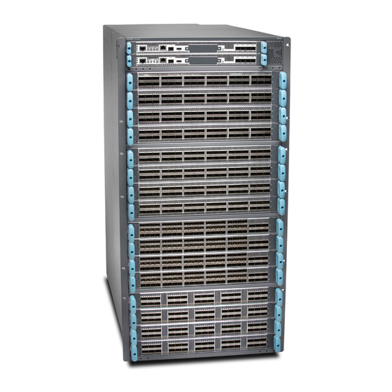
Page 2: Meet The Qfx10016
Switch Interface Boards (SIBs), power supplies, fan trays, and line cards. The switch chassis ships in a cardboard box that has a two-layer wooden pallet base. The switch chassis is bolted to the pallet base. You can install a QFX10016 switch in a standard 19 in. - Page 3 Cooling and Airflow Requirements The cooling system in a QFX10016 chassis consists of dual fan trays and dual fan tray controllers. There is no air filter in a QFX10016. The air intake to cool the chassis is located on the port (line card) side of the chassis. Air flows into the chassis from the ports in the control boards and line cards, through the Switch Interface Boards (SIBs), and exits from the fan trays and the power supplies.
-
Page 4: Unpack The Qfx10016
Unpack the QFX10016 Here’s how to unpack the chassis for QFX10016: Move the shipping box to a staging area as close to the installation site as possible. While the chassis is bolted to the pallet, you can use a forklift or pallet jack to move it. Make sure there is enough space to remove components from the chassis. -
Page 5: Mount The Switch Chassis
IN THIS SECTION Install the Mounting Hardware | 5 Mount the QFX10016 using a Mechanical Lift | 6 To install the QFX10016, first install the mounting hardware and then use a mechanical lift to load the chassis into the rack. •... - Page 6 Hand-tighten the screws fully (to 12–16 in.-lb torque) using a number 2 Phillips screwdriver. Mount the QFX10016 using a Mechanical Lift Because of the switch's size and weight, the QFX100016 can safely be installed only by using a mechanical lift.
-
Page 7: Install The Qfx10016
9. After ensuring that the switch is aligned properly, tighten the screws. Install the QFX10016 IN THIS SECTION What's in the Box? | 8... - Page 8 What's in the Box? Along with your QFX10016, you’ll also find: • An accessory kit which includes: • AC Power cord (country specific). • Power cord retainer clips. • Electrostatic discharge (ESD) wrist strap with cable. • A Phillips (+) screwdriver, number 1, 2, or 3, depending on the size of your rack-mounting screws.
- Page 9 To Install a DC Power Supply • DC power source cables (not provided) with the cable lugs (provided) attached. The provided terminal lugs in a QFX10016 are sized for 4 AWG (21.1 mm2) power source cables. The DC power source cables that you provide...
-
Page 10: Install The Line Cards
must be 4 AWG (21.1 mm2), minimum 60°C wire. We recommend that you install heat-shrink tubing insulation around the crimped section of the power cables and lugs. • 13/32 in. (10 mm) nut driver or socket wrench. • Phillips (+) screwdrivers, numbers 1 and 2. •... -
Page 11: Install The Front Panel
You can install the optional cable management kit after the card is installed. Install the Front Panel The front panel is required on the QFX10016 to protect fiber optic cabling and to provide additional protection from electromagnetic interference (EMI). The front panel can be installed with or without the optional cable management system. - Page 12 3. Use the Phillips screwdriver to attach two mounting screws to the right base bracket at the bottom right side of the chassis frame. 4. Use the Phillips screwdriver to attach two mounting screws to the latch bracket at the top left of the chassis frame. 5.
-
Page 13: Connect Power To The Chassis
There are mounting holes for the terminal bracket on the left-rear side of the chassis to connect to the earth ground. Before you connect earth ground to the protective earthing terminal of a QFX10016, ensure that a licensed electrician has attached an appropriate grounding lug to the grounding cable. - Page 14 QFX10016 power supplies are hot-insertable and are field-replaceable units (FRUs). You can install up to 10 power supplies in a QFX10016. The power supplies install in the rear of the chassis in the slots provided along the left side. CAUTION: Do not mix AC and DC power supplies in the same chassis.
- Page 15 Taking care not to touch power supply connections, remove the power supply from its bag. Peel back and remove the protective plastic wrap that covers all four sides of the power supply. Ensure that the power switch is set to the standby (O) position. This switch turns off the output voltage; it does not interrupt AC.
- Page 16 QFX10016 power supplies are hot-insertable and are field-replaceable units (FRUs). You can install up to 10 power supplies in a QFX10016. The power supplies install in the rear of the chassis in the slots provided along the left side. CAUTION: Do not mix AC and DC power supplies in the same chassis.
- Page 17 For installations that require a separate grounding conductor to the chassis, use the protective earthing terminal on the switch chassis to connect to earth ground. For instructions on connecting a QFX10016 switch to ground using a separate grounding conductor, see "Ground the Chassis"...
- Page 18 Each power supply has two independent sets of DC power input terminals (INPUT 1: RTN –48V/–60V: and INPUT 2: : RTN –48V/–60V). For feed redundancy, each power supply must be powered by dedicated power feeds derived from feed INPUT 1 and feed INPUT 2. This configuration provides the commonly deployed INPUT 1 / INPUT 2 feed redundancy for the switch.
-
Page 19: Step 2: Up And Running
Step 2: Up and Running IN THIS SECTION Connect to the Network | 20 Perform Initial Configuration | 20 Now that the QFX10016 is powered on, let’s do some initial configuration to get it up and running on the network. - Page 20 2. Connect the other end of the Ethernet cable into the console server. Perform Initial Configuration You must perform the initial configuration of a QFX10016 switch through the console port using the CLI. Before you begin connecting and configuring the switch, set the following parameter values on the console server or PC, verify that the following default serial port settings are configured on your laptop or desktop PC: •...
- Page 21 Log in as root. There is no password. If the software booted before you connected to the console port, you might need to press the Enter key for the prompt to appear. login: root Start the CLI. root@% cli Enter configuration mode. root>...
-
Page 22: Step 3: Keep Going
[edit] root@# set system services telnet NOTE: When Telnet is enabled, you cannot log in to a QFX10016 through Telnet using root credentials. Root login is allowed only for SSH access. 11. Commit the configuration to activate it on the switch. - Page 23 Configure time-based protocols for your network devices See the Time Management Administration Guide running Junos OS See, automate, and protect your network with Juniper Security Visit the Security Design Center Get hands-on experience with the procedures covered in this Visit...
- Page 24 Juniper Learning Portal Juniper Juniper Networks, the Juniper Networks logo, Juniper, and Junos are registered trademarks of Juniper Networks, Inc. in the United States and other countries. All other trademarks, service marks, registered marks, or registered service marks are the property of their respective owners.
Need help?
Do you have a question about the QFX10016 and is the answer not in the manual?
Questions and answers