Juniper QFX10016 Quick Start Manual
Hide thumbs
Also See for QFX10016:
- Hardware manual (439 pages) ,
- Quick start manual (24 pages) ,
- Hardware manual (368 pages)
Table of Contents
Advertisement
Quick Links
QFX10016 Switch Quick Start Guide
August 2016
Part Number: 530-068238
Revision 01
Contents
Copyright © 2016, Juniper Networks, Inc.
This document describes how to install the Juniper Networks
Quick Start Description . . . . . . . . . . . . . . . . . . . . . . . . . . . . . . . . . . . . . . . . . . . . . . . 2
Step 1-Preparing the Site for the QFX10016 . . . . . . . . . . . . . . . . . . . . . . . . . . . . . . . 2
Rack-Mounting Requirements . . . . . . . . . . . . . . . . . . . . . . . . . . . . . . . . . . . . . . 2
Clearance Requirements . . . . . . . . . . . . . . . . . . . . . . . . . . . . . . . . . . . . . . . . . . . 3
Cooling and Airflow Requirements . . . . . . . . . . . . . . . . . . . . . . . . . . . . . . . . . . . 3
Step 2-Unpacking the QFX10016 . . . . . . . . . . . . . . . . . . . . . . . . . . . . . . . . . . . . . . . 4
Step 3-Mounting the Switch Chassis . . . . . . . . . . . . . . . . . . . . . . . . . . . . . . . . . . . . 7
Installing the Mounting Hardware . . . . . . . . . . . . . . . . . . . . . . . . . . . . . . . . . . . 7
Mounting the QFX10016 Using a Mechanical Lift . . . . . . . . . . . . . . . . . . . . . . . 9
Step 4-Installing Line Cards . . . . . . . . . . . . . . . . . . . . . . . . . . . . . . . . . . . . . . . . . . . 12
Step 5-Installing the Front Panel . . . . . . . . . . . . . . . . . . . . . . . . . . . . . . . . . . . . . . 15
Step 6-Connecting Power to the Chassis . . . . . . . . . . . . . . . . . . . . . . . . . . . . . . . . 17
Ground the Chassis . . . . . . . . . . . . . . . . . . . . . . . . . . . . . . . . . . . . . . . . . . . . . . 17
Install AC Power Supplies . . . . . . . . . . . . . . . . . . . . . . . . . . . . . . . . . . . . . . . . 20
Install DC Power Supplies . . . . . . . . . . . . . . . . . . . . . . . . . . . . . . . . . . . . . . . . . 23
Step 7-Connecting to the Network . . . . . . . . . . . . . . . . . . . . . . . . . . . . . . . . . . . . . 28
Step 8-Performing Initial Configuration . . . . . . . . . . . . . . . . . . . . . . . . . . . . . . . . . 28
Safety Warnings Summary . . . . . . . . . . . . . . . . . . . . . . . . . . . . . . . . . . . . . . . . . . . 30
Power Cable Warning (Japanese) . . . . . . . . . . . . . . . . . . . . . . . . . . . . . . . . . . . 31
®
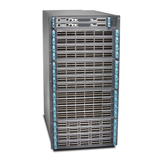
QFX10016 Switch Chassis.
1
Advertisement
Table of Contents

Related Manuals for Juniper QFX10016


Summary of Contents for Juniper QFX10016
-
Page 1: Table Of Contents
Quick Start Description ..........2 Step 1–Preparing the Site for the QFX10016 ....... 2 Rack-Mounting Requirements . -
Page 2: Quick Start Description
QFX10016 switch in a standard 19 in. (483 mm) equipment rack by using the supplied rack-mounting kit and the front-mounting bracket that is attached to the chassis. Before you install the QFX10016, make sure the site meets all of the power, cooling, and clearance requirements. See the site preparation guidelines and power requirements in... -
Page 3: Clearance Requirements
Figure 1: Clearance Requirements for Airflow and Hardware Maintenance for a QFX10016 If you are mounting a QFX10016 in a rack with other equipment, ensure that the exhaust from other equipment does not blow into the intake vents of the chassis. -
Page 4: Step 2-Unpacking The Qfx10016
Leave at least 24 in. (61 cm) both in front of and behind the QFX10016 for service personnel to remove and install hardware components. To be NEBS GR-63 compliant, allow at least 30 in. - Page 5 The shipper has the option to either ship the front panel separately or to ship along with the chassis. If the front panel arrives with the chassis, set aside the front panel box until you are ready to verify the contents of the order. Copyright © 2016, Juniper Networks, Inc.
- Page 6 QFX10016 Switch Quick Start Guide To unpack the chassis (see Figure 3 on page Figure 3: Shipping Crate and Accessory Box Move the shipping box to a staging area as close to the installation site as possible. While the chassis is bolted to the pallet, you can use a forklift or pallet jack to move it.
-
Page 7: Step 3-Mounting The Switch Chassis
Save the shipping box and packing materials in case you need to move or ship the switch at a later time. Step 3–Mounting the Switch Chassis To install the QFX10016, first install the mounting hardware and then use a mechanical lift to load the chassis into the rack. Installing the Mounting Hardware on page 7... - Page 8 QFX10016 Switch Quick Start Guide NOTE: Two-post installation racks are not supported. The four mounting bracket pieces are: 1 left front mounting bracket. The bracket is labeled “LEFT FRONT” on the side of the bracket that faces the interior of the rack, near the holes for attaching the bracket to the rack.
-
Page 9: Mounting The Qfx10016 Using A Mechanical Lift
Mounting the QFX10016 Using a Mechanical Lift Hand-tighten the screws fully (to 12–16 in.-lb torque) using a number 2 Phillips screwdriver. Figure 5: Mounting Brackets for 4-Post Rack Installation 1— Front adjustable mounting brackets 2— Rear adjustable mounting brackets Position the right front adjustable mounting bracket at the desired position in the right side of the rack opposite the installed left front bracket, so that it is on the same rack level as the left bracket. - Page 10 QFX10016 Switch Quick Start Guide CAUTION: Do not install line cards in the chassis until after you mount the chassis securely on a rack or cabinet. CAUTION: Before front-mounting the switch on a rack or cabinet, have a qualified technician verify that the rack or cabinet is strong enough to support the switch's weight and is adequately supported at the installation site.
- Page 11 Mounting the QFX10016 Using a Mechanical Lift Figure 6: Loading the QFX10016 into a Rack Using a Mechanical Lift Using the lift, align the switch in front of the rack, centering it in front of the mounting brackets. Lift the chassis approximately 0.75 in. (1.9 cm) above the surface of the mounting brackets.
-
Page 12: Step 4-Installing Line Cards
QFX10016 Switch Quick Start Guide Figure 7: Attaching Front-Mounting Brackets Move the lift away from the rack. Install a mounting screw into each of the open front-mounting holes aligned with the rack, starting from the bottom. Visually inspect the alignment of the switch. If the switch is installed properly in the rack, all the mounting screws on one side of the rack are aligned with the mounting screws on the opposite side and the switch is level. - Page 13 Lifting the line card by the handles or edge connectors might bend them, which would prevent the line cards from being properly seated in the chassis. See Figure 10 on page Copyright © 2016, Juniper Networks, Inc.
- Page 14 QFX10016 Switch Quick Start Guide Figure 10: Line Card Connectors 1— Connectors Remove the line card from the electrostatic bag and inspect it for any damage before installing it into the chassis. Grasp and lift the line card by the sides.
-
Page 15: Step 5-Installing The Front Panel
Step 5–Installing the Front Panel Step 5–Installing the Front Panel The front panel is required on the QFX10016 to protect fiber optic cabling and to provide additional protection from electromagnetic interference (EMI). The front panel can be installed with or without the optional cable management system. - Page 16 QFX10016 Switch Quick Start Guide Use the Phillips screwdriver to attach two mounting screws to the latch bracket at the top left of the chassis frame (see Figure 13 on page 16). Figure 13: Attaching Front Panel Brackets Use the final two mounting screws to attach a latch bracket to the top right of the chassis frame so there are brackets on all four corners of the front of the chassis.
-
Page 17: Step 6-Connecting Power To The Chassis
Step 6–Connecting Power to the Chassis Figure 14: Front Panel Installation Step 6–Connecting Power to the Chassis Before supplying power to the QFX10016, complete ensure you complete these tasks: Ground the Chassis on page 17 Install AC Power Supplies on page 20... - Page 18 Grounding lug for your grounding cable (provided)—This bracket attaches to the lower left corner of the QFX10016 switch chassis next to PSU 5, providing a protective earthing terminal for the switch. The grounding lug required is a Panduit LCD6-10A-L or equivalent.
- Page 19 Place the chassis grounding lug and cable over the PEM nuts with the cable connection pointing to the left. See Figure 16 on page Figure 16: Connecting a Grounding Cable to the QFX10016 Place the two screws over the grounding lug and grounding cable. Tighten the two screws using a Phillips screwdriver.
-
Page 20: Install Ac Power Supplies
Install AC Power Supplies QFX10016 power supplies are hot-insertable and are field-replaceable units (FRUs). You can install up to 10 power supplies in a QFX10016. The power supplies install in the rear of the chassis in the slots provided along the left side. - Page 21 Figure 18: Installing an AC Power Supply Locate two power cords shipped with the switch; the cords have plugs appropriate for your geographical location. Attach each power cord to a dedicated AC power source outlet. Copyright © 2016, Juniper Networks, Inc.
- Page 22 QFX10016 Switch Quick Start Guide Squeeze the two sides of the power cord retainer clip and insert the ends of the clip into the holes in the bracket on each side of the AC appliance inlets on the AC power supply faceplate.
-
Page 23: Install Dc Power Supplies
Install DC Power Supplies QFX10016 power supplies are hot-insertable and are field-replaceable units (FRUs). You can install up to 10 power supplies in a QFX10016. The power supplies install in the rear of the chassis in the slots provided along the left side. - Page 24 QFX10016 Switch Quick Start Guide Phillips (+) screwdrivers, numbers 1 and 2 Multimeter To install a DC power supply in a QFX10016 (see Figure 22 on page 27): Attach the electrostatic discharge (ESD) grounding strap to your bare wrist, and connect the strap to the ESD point on the chassis.
- Page 25 INPUT 2. This configuration provides the commonly deployed INPUT 1 / INPUT 2 feed redundancy for the switch. Figure 20: Connecting the DC Power Supply Cables to a QFX10016 Install the plastic cable cover over each set of power cables by using the Phillips (+) screwdriver, number 2, to tighten the screw.
- Page 26 QFX10016 Switch Quick Start Guide Figure 21: Removing the PSU Cover Panel Unscrew the captive screw in the counterclockwise direction by using the Phillips (+) screwdriver, number 1. Pull the captive screw away from the faceplate of the power supply to release the latch.
- Page 27 (on). Figure 23: Setting the Enable Switches for the Power Source 1— Source input 1 2— Source input 2 Copyright © 2016, Juniper Networks, Inc.
-
Page 28: Step 7-Connecting To The Network
Console Server Figure 25: Connecting a Switch Directly to a Management Console Step 8–Performing Initial Configuration You must perform the initial configuration of a QFX10016 switch through the console port using the command-line interface (CLI). Copyright © 2016, Juniper Networks, Inc. - Page 29 Configure the default gateway. [edit] root@# set routing-options static route default next-hop address Configure the IP address and prefix length for the switch management interface. [edit] root@# set interfaces em0 unit 0 family inet address address/prefix-length Copyright © 2016, Juniper Networks, Inc.
-
Page 30: Safety Warnings Summary
Permit only trained and qualified personnel to install or replace switch components. Perform only the procedures described in this quick start and the QFX10016 switch documentation. Other services must be performed only by authorized service personnel. Before installing the switch, read the planning instructions in the QFX10016 switch documentation to make sure that the site meets power, environmental, and clearance requirements for the switch. -
Page 31: Power Cable Warning (Japanese)
A base AC configuration is 533 lb (241.77 kg) and redundant AC configurations can weigh 596 lb (270.34 kg). Installing the QFX10016 switch in a rack or cabinet requires either a mechanical lift or three people to lift the switch and another person to secure it to the rack.
Need help?
Do you have a question about the QFX10016 and is the answer not in the manual?
Questions and answers