Juniper QFX10016 Hardware Manual
Hide thumbs
Also See for QFX10016:
- Hardware manual (439 pages) ,
- Quick start manual (31 pages) ,
- Hardware manual (306 pages)

Related Manuals for Juniper QFX10016


Summary of Contents for Juniper QFX10016
- Page 1 QFX10016 Switch Hardware Guide Modified: 2017-08-11 Copyright © 2017, Juniper Networks, Inc.
- Page 2 END USER LICENSE AGREEMENT The Juniper Networks product that is the subject of this technical documentation consists of (or is intended for use with) Juniper Networks software. Use of such software is subject to the terms and conditions of the End User License Agreement (“EULA”) posted at http://www.juniper.net/support/eula/.
-
Page 3: Table Of Contents
Chassis Components and Descriptions ....... 17 QFX10016 Chassis Physical Specifications ....... 17 QFX10000 Field-Replaceable Units . - Page 4 QFX10016 Cooling System and Airflow ........33...
- Page 5 QFX10016 Installation Overview ........
- Page 6 Installing a Transceiver ..........254 Disconnecting a Fiber-Optic Cable from a Device ......256 Copyright © 2017, Juniper Networks, Inc.
- Page 7 QFX10016 ........
- Page 8 Installation Instructions Warning ........305 QFX10016 Chassis Lifting Guidelines ........306 Restricted Access Warning .
- Page 9 Figure 23: Airflow Through a QFX10016 ........
- Page 10 Figure 32: SIBs Installed in a QFX10016 ........
- Page 11 Figure 67: ESD Point for the QFX10016 ....... . .
- Page 12 Figure 118: Installing a QFX10016 SIB ........
- Page 13 Figure 157: QFX10008 Serial Number Label ......270 Figure 158: QFX10016 Serial Number Label ......271 Figure 159: QFX10000 AC Power Supply Serial Number Location .
- Page 14 QFX10016 Switch Hardware Guide Copyright © 2017, Juniper Networks, Inc.
-
Page 15: List Of Tables
Table 19: Dimensions of a QFX10016 SIB ....... . 52... - Page 16 Table 29: QFX10K-12C-DWDM Modulation Formats ..... . . 73 Table 30: Juniper Networks Compatible Products in 100 Gbps Mode ..73 Table 31: QFX10K-12C-DWDM Optical Transmit Specifications .
- Page 17 Models ............290 Copyright © 2017, Juniper Networks, Inc.
- Page 18 QFX10016 Switch Hardware Guide xviii Copyright © 2017, Juniper Networks, Inc.
-
Page 19: About The Documentation
® To obtain the most current version of all Juniper Networks technical documentation, see the product documentation page on the Juniper Networks website at http://www.juniper.net/techpubs/ If the information in the latest release notes differs from the information in the documentation, follow the product Release Notes. -
Page 20: Table 1: Notice Icons
RFC 1997, BGP Communities Attribute Italic text like this Represents variables (options for which Configure the machine’s domain name: you substitute a value) in commands or [edit] configuration statements. root@# set system domain-name domain-name Copyright © 2017, Juniper Networks, Inc. -
Page 21: Documentation Feedback
We encourage you to provide feedback, comments, and suggestions so that we can improve the documentation. You can provide feedback by using either of the following methods: Online feedback rating system—On any page of the Juniper Networks TechLibrary site , simply click the stars to rate the content, http://www.juniper.net/techpubs/index.html and use the pop-up form to provide us with information about your experience. -
Page 22: Requesting Technical Support
7 days a week, 365 days a year. Self-Help Online Tools and Resources For quick and easy problem resolution, Juniper Networks has designed an online self-service portal called the Customer Support Center (CSC) that provides you with the following features: Find CSC offerings: http://www.juniper.net/customers/support/... - Page 23 About the Documentation For international or direct-dial options in countries without toll-free numbers, see http://www.juniper.net/support/requesting-support.html Copyright © 2017, Juniper Networks, Inc. xxiii...
- Page 24 QFX10016 Switch Hardware Guide xxiv Copyright © 2017, Juniper Networks, Inc.
-
Page 25: Overview
Control Board Components and Descriptions on page 27 Cooling System Components and Descriptions on page 33 Power System Components and Descriptions on page 43 Switch Fabric Components and Descriptions on page 51 Line Card Components and Descriptions on page 55 Copyright © 2017, Juniper Networks, Inc. - Page 26 QFX10016 Switch Hardware Guide Copyright © 2017, Juniper Networks, Inc.
-
Page 27: System Overview
The largest of the QFX10000 line of switches, the QFX10016 can provide 96 Tbps of throughput and 32 Bpps of forwarding capacity in a 21 rack unit (21 U) chassis. The... -
Page 28: Chassis Description
Power Supplies on page 10 Software on page 11 Chassis Description The QFX10016 is 21 U tall. Two QFX10016 chassis can fit in a standard 42 U rack with adequate cooling and power. All key QFX10016 components are field-replaceable units (FRUs). -
Page 29: System Overview
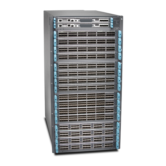
Chapter 1: System Overview Figure 1: QFX10016 Chassis Front 1— Control Boards 4— Installation holes for the front panel 2— Status LED panel 5— Line card slots 0-15 (numbered top to bottom) 3—Handles Copyright © 2017, Juniper Networks, Inc. -
Page 30: Figure 2: Qfx10016 Chassis Rear
QFX10016 Switch Hardware Guide Figure 2: QFX10016 Chassis Rear 1— AC or DC power supplies 3— ESD point 2— Fan trays with redundant fans 4— Protective earthing terminal Copyright © 2017, Juniper Networks, Inc. -
Page 31: Control Board
The Control Board (see Figure 4 on page 8) contains a Routing Engine and is responsible for the system management and system control in QFX10016. See “QFX10000 Control Board Description” on page 27. Control Boards are FRUs that are installed in the front of the chassis in the slots labeled . -
Page 32: Line Cards
Figure 4: QFX10000 Control Board Line Cards The QFX10016 features 16 horizontal line card slots and supports line rate for each line card. The line cards combine a Packet Forwarding Engine (PFE) and Ethernet interfaces enclosed in a single assembly. The QFX10000 line card architecture is based on a number of identical, independent PFE slices, each with 500 Gbps full-duplex throughput. -
Page 33: Sibs
Figure 6 on page 9). Each QFX10016 SIB has 16 connectors that match to a line card slot, eliminating the need for a backplane. When all six SIBs are installed, the QFX10016 has a net switching capacity of 96 Tbps. See “QFX10016 Switch Interface Board... -
Page 34: Cooling System
QFX10016 Switch Hardware Guide Cooling System The cooling system in a QFX10016 consists of two hot-removable and hot-insertable FRU fan trays (see Figure 7 on page 10) and two fan tray controllers (see Figure 8 on page 10). Each fan tray contains 21 fans. The fan trays install vertically on the rear of the chassis and provide front-to-back chassis cooling. -
Page 35: Software
2 and Layer 3 switching, routing, and security services. The same Junos OS code base that runs on QFX Series switches also runs on all Juniper Networks EX Series, M Series, MX Series, and T Series routers and SRX Series Services Gateways. The minimum Junos OS release is 15.1X53-D61. -
Page 36: Qfx10016 Components And Configurations
QFX10000-30C Line Card on page 61 QFX10016 Components and Configurations Table 4 on page 12 lists the four hardware configurations for a QFX10016 modular chassis—base (AC version), and redundant (AC and DC versions)—and the components included in each configuration. Table 4: QFX10016 Hardware Configurations... -
Page 37: Qfx10000 Component Redundancy
QFX10000 AC Power Supply on page 43 QFX10000 DC Power Supply on page 46 QFX10016 Switch Interface Board Description on page 51 QFX10000 Component Redundancy The QFX10000 is designed so that no single point of failure can cause the entire system to fail. -
Page 38: Qfx10000 Hardware And Cli Terminology Mapping
If one of the fans fails, the host subsystem increases the speed of the remaining fans to provide sufficient cooling for the switch indefinitely. See QFX10008 Cooling System and Airflow and “QFX10016 Cooling System and Airflow” on page Related QFX10016 Hardware Overview on page 3... - Page 39 DPC equivalents on the switch. PIC (n) – Value of n is always 0. – Understanding Interface Naming Conventions Related QFX10016 Hardware Overview on page 3 Documentation QFX10008 Hardware Overview Configuring a QFX10000 on page 171 Copyright © 2017, Juniper Networks, Inc.
- Page 40 QFX10016 Switch Hardware Guide Copyright © 2017, Juniper Networks, Inc.
-
Page 41: Chassis Components And Descriptions
The QFX10016 modular-chassis is a rigid sheet-metal structure that houses the field-replaceable units (FRUs). You can mount up to two QFX10016 chassis in a standard 19-in. 4-post rack (42 U) rack, provided the rack can handle the combined weight and there is adequate power and cooling.Table 6 on page 17... - Page 42 QFX10016 Switch Hardware Guide Table 6: QFX10016 Physical Specifications (continued) Description Weight Height Width Depth Chassis redundant DC 591 lb 36.6 in. 17.4 in. (44.2 cm) 35 in. (88.9 cm) configuration (268.07 kg) (92.96 cm) NOTE: The outer edges of the...
-
Page 43: Chassis Components And Descriptions
Four-Post Rack Using a Mechanical Lift” on page 153 for instructions for properly moving a loaded chassis. Related QFX10000 Rack Requirements on page 109 Documentation QFX10016 Components and Configurations on page 12 QFX10016 Cooling System and Airflow on page 33 Copyright © 2017, Juniper Networks, Inc. -
Page 44: Qfx10000 Field-Replaceable Units
(offline | online) slot slot-number offline Line cards Hot-insertable and hot-removable. We recommend that you take line cards offline before removing them. For example: user@switch> request chassis fpc slot slot-number offline Copyright © 2017, Juniper Networks, Inc. -
Page 45: Qfx10000 Status Panel Leds
Determining QFX10000 Optical Transceiver and Cable Support on page 127 QFX10000 Status Panel LEDs The status panel of the QFX10008 and QFX10016 shows the overall status of the chassis through a set of five bi-color LEDs (see Figure 12 on page 22). -
Page 46: Figure 12: Status Panel
One or more SIBs are offline. Line cards Green On steadily All installed line cards are online. Yellow On steadily One or more line cards have an error condition. None One or more line cards are offline. Copyright © 2017, Juniper Networks, Inc. -
Page 47: Qfx10000 Optional Equipment
QFX10000-36Q Line Card on page 55 QFX10000-30C Line Card on page 61 QFX10008 Cooling System and Airflow QFX10016 Cooling System and Airflow on page 33 QFX10008 Switch Interface Board Description QFX10016 Switch Interface Board Description on page 51 QFX10000 AC Power Supply on page 43... -
Page 48: Figure 13: Qfx10000 Cable Management System
Figure 14: Cable Management Parts 1— Handle extensions 2— Cable tray Cables are draped across or under the handle extensions and then secured with cable wraps (see Figure 15 on page 25). Copyright © 2017, Juniper Networks, Inc. -
Page 49: Qfx10000 Sata Ssd
Chapter 2: Chassis Components and Descriptions Figure 15: Two Cable Management Systems Installed on QFX10016 QFX10000 SATA SSD The QFX10000 line of modular chassis switches allows you to install one of two Serial Advanced Technology Attachment (SATA) solid-state drives (SSDs) as a secondary boot drive or for log storage. - Page 50 QFX10016 Switch Hardware Guide Copyright © 2017, Juniper Networks, Inc.
-
Page 51: Control Board Components And Descriptions
QFX10000 Control Board Description on page 27 QFX10000 Control Board LEDs on page 28 QFX10000 Control Board Description The Control Board is responsible for system management in a QFX10008 or QFX10016 (see Figure 17 on page 27). The switch chassis can run with one or two Control Boards. -
Page 52: Control Board Components
Handling and Storing QFX10000 Line Cards, Control Boards, and SIBs on page 213 Documentation Installing a QFX10000 Control Board on page 239 QFX10000 Control Board LEDs The QFX10000 Control Boards have four types of LED indicators (see Figure 19 on page 29). Copyright © 2017, Juniper Networks, Inc. -
Page 53: Control Board Status Panel Leds
Table 9: Control Board Status LEDs Color State Description Green On steadily The Control Board is receiving adequate power. Yellow Blinking The Control Board has detected an error. Dark Unlit The Control Board is not powered up. Copyright © 2017, Juniper Networks, Inc. -
Page 54: Qfx10000 Management Port Leds
The Control Board is the backup. QFX10000 Management Port LEDs There are two management ports on the Control Board of a QFX10008 and QFX10016 that have LEDs that indicate link status and link activity. These two ports, located on the Control Board panel between the clocking connections and the USB port, are both labeled . -
Page 55: Sata Ssd Leds
Table 12: Control Board Status LEDs Color State Description Green On steadily A SATA drive is present. Green Blinking The drive is active. Yellow On steadily The drive is active. Dark Unlit A drive is not installed. Copyright © 2017, Juniper Networks, Inc. -
Page 56: Virtual Port Connections
QFX10016 Switch Hardware Guide Virtual Port Connections The four small form-factor pluggable plus (SFP+) ports are reserved for future use. Related Connecting a QFX10000 to a Network for Out-of-Band Management Documentation Copyright © 2017, Juniper Networks, Inc. -
Page 57: Cooling System Components And Descriptions
QFX10000 Fan Tray LEDs and Fan Tray Controller LEDs on page 37 QFX10016 Cooling System and Airflow The cooling system in a QFX10016 chassis consists of dual fan trays and dual fan tray controllers. There is no air filter in a QFX10016. -
Page 58: Figure 22: Fan Trays For A Qfx10016
QFX10016 Switch Hardware Guide Figure 22: Fan Trays for a QFX10016 Table 13 on page 34 for the physical specifications for the fan trays. Table 13: QFX10016 Fan Tray Specifications Specification Value Height 36.6 in. (92.97 cm) Width 6.6 in. (16.8 cm) Depth 4.0 in. -
Page 59: Fan Tray Controller
Spinning at normal speed Fan Tray 1 Fan 8 4500 Spinning at normal speed Fan Tray 1 Fan 9 4650 Spinning at normal speed Fan Tray 1 Fan 10 4500 Spinning at normal speed Copyright © 2017, Juniper Networks, Inc. -
Page 60: Airflow Direction In The Qfx10016
Weight 1.5 lbs. (0.68 kg) Airflow Direction in the QFX10016 The air intake to cool the chassis is located on the port (line card) side of the chassis. Air flows into the chassis from the ports in the Control Boards and line cards, through the Switch Interface Boards (SIBs), and exits from the fan trays and the power supplies. -
Page 61: Qfx10000 Fan Tray Leds And Fan Tray Controller Leds
Chapter 4: Cooling System Components and Descriptions Figure 23: Airflow Through a QFX10016 The fan tray continues to operate indefinitely and provides sufficient cooling even when a single fan fails, provided the room temperature is within the operating range. You can check the status of fans by viewing the LEDs on each fan tray. -
Page 62: Fan Tray Leds
To maintain proper airflow through the chassis, leave the fan tray installed in the chassis until you are ready to replace it. None The fan is not receiving power from the fan tray controller. Copyright © 2017, Juniper Networks, Inc. - Page 63 SIB in the grouping of 3. To maintain proper airflow through the chassis, leave the fan tray installed in the chassis until you are ready to replace the SIB. None The SIB is offline. Copyright © 2017, Juniper Networks, Inc.
- Page 64 SIB in the grouping of 3. To maintain proper airflow through the chassis, leave the fan tray installed in the chassis until you are ready to replace the SIB. None The SIB is offline. Copyright © 2017, Juniper Networks, Inc.
-
Page 65: Fan Tray Controller Leds
LEDs on the fan tray controller panel. Figure 25: Fan Tray Controller LEDs on a QFX10000 1— Fan tray controller power 2— Fan tray controller status Table 16 on page 42 describes the functions of the fan tray controller LEDs. Copyright © 2017, Juniper Networks, Inc. -
Page 66: Table 16: Fan Tray Controller Leds On A Qfx100000
Related QFX10008 Cooling System and Airflow Documentation QFX10016 Cooling System and Airflow on page 33 Installing a QFX10000 Fan Tray on page 177 Removing a QFX10000 Fan Tray on page 180 Installing a QFX10000 Fan Tray Controller on page 185 Removing a QFX10000 Fan Tray Controller on page 187 Copyright ©... -
Page 67: Power System Components And Descriptions
(top to bottom) located in the rear of the chassis. PSU 0 PSU 5 In QFX10016, you can install up to 10 power supplies in the slots labeled through PSU 0 PSU 9 . Power supplies install in any available power supply slot. - Page 68 NOTE: All base configuration QFX10008 switches are shipped with three power supplies; base configuration for QFX10016 switches are shipped with five power supplies. Cover panels are installed over the remaining power supply slots. You can add additional power supplies to base configuration switches as necessary.
-
Page 69: Power System Components And Descriptions
QFX10000 AC Power Specifications on page 119 Documentation QFX10000 AC Power Supply LEDs on page 48 Installing a QFX10000 AC Power Supply on page 189 Removing a QFX10000 AC Power Supply on page 194 Copyright © 2017, Juniper Networks, Inc. -
Page 70: Qfx10000 Dc Power Supply
Each DC power supply has a power switch with international markings for on ( ) and off ), a fan, and four LEDs on the faceplate that indicate the status of the power supply. Figure 28 on page Copyright © 2017, Juniper Networks, Inc. -
Page 71: Figure 28: Dc Power Supply
DC feed. The chosen breaker should be sized to deliver 60 A of input current. Each power supply connects to the combined power rail in a QFX10008 or QFX10016. The power rail distributes the output power produced by the power supplies to different switch components. -
Page 72: Qfx10000 Ac Power Supply Leds
AC is within operating range (200–240 VAC). Dark Unlit The power supply is switched off. Green Solid DC power output is within normal operating range. PWR OK Yellow Blinking The output is out of the limits. Copyright © 2017, Juniper Networks, Inc. -
Page 73: Qfx10000 Dc Power Supply Leds
LEDs display information about the status of the power supply. See Figure 30 on page Figure 30: LEDs on a DC Power Supply in QFX10000 Switches 1— INP1–Source input 1 3— PWR OK 2— INP2–Source input 2 4— FAULT Copyright © 2017, Juniper Networks, Inc. -
Page 74: Table 18: Leds On An Dc Power Supply In Qfx10000
QFX10016 Switch Hardware Guide Table 18 on page 50 describes the LEDs in QFX10008 and QFX10016 modular chassis. Table 18: LEDs on an DC Power Supply in QFX10000 Color State Description Yellow Blinking Indicates one of the following: INP1 INP2 DC power input voltage is not within normal operating range. -
Page 75: Switch Fabric Components And Descriptions
Control Boards in the front and the fan trays in the rear. When all six SIBs are installed, the QFX10016 has a net switching capacity of 96 Tbps. The SIBs make up the QFX10016 switching plane. Five SIBs are required for operation, with the sixth providing N+1 redundancy. The sixth SIB is powered and available to the system at all times. -
Page 76: Figure 31: Qfx10016 Sib
QFX10016 Switch Hardware Guide Figure 31: QFX10016 SIB Table 19 on page 52 shows the physical specifications for a QFX10016 SIB. Table 19: Dimensions of a QFX10016 SIB Specification Value Height 34.6 in. (87.88 cm) Width 1.8 in. (4.57 cm) Depth 10.4 in. -
Page 77: Qfx10000 Switch Interface Board Leds
Chapter 6: Switch Fabric Components and Descriptions Figure 32: SIBs Installed in a QFX10016 1— Fan tray controllers 2— SIBs Related Installing a QFX10000 Switch Interface Board on page 216 Documentation Removing a QFX10000 Switch Interface Board on page 221 QFX10000 Switch Interface Board LEDs The Switch Interface Board (SIB) has two status LEDs at the top of each board. -
Page 78: Figure 33: Sib Leds
Unlit The fan tray controller is having a power problem. Related Handling and Storing QFX10000 Line Cards, Control Boards, and SIBs on page 213 Documentation Installing a QFX10000 Switch Interface Board on page 216 Copyright © 2017, Juniper Networks, Inc. -
Page 79: Line Card Components And Descriptions
The line cards are hot-insertable and hot-removable; you can remove and replace them without powering off the switch or disrupting switch functions. See Figure 34 on page Copyright © 2017, Juniper Networks, Inc. -
Page 80: Switch Ports
You can use 40-Gigabit Ethernet QSFP+ transceivers and QSFP+ DAC cablesin any downstream port. See “Determining QFX10000 Optical Transceiver and Cable Support” on page 127. Uplink ports You can configure all the QSFP+ ports as uplinks. Copyright © 2017, Juniper Networks, Inc. -
Page 81: Figure 35: All Ports Are Enabled For 40-Gigabit Ethernet By Default
10-Gigabit Ethernet ports, or bundled with the next two consecutive ports and channelized into twelve 10-Gigabit Ethernet ports as a port range. Only the first and fourth port in each 6XQSFP cage are available to channelize a port range (see Figure 38 on page 58). Copyright © 2017, Juniper Networks, Inc. -
Page 82: Figure 38: Use The First And Fourth Port In Each 6Xqsfp Cage To Channelize A
Port Number Ethernet Port Group Ethernet Ethernet 100-Gigabit Ethernet Disables – – 0, 2 – – – – – – 3, 4 – – 6, 8 – – – – – – 9, 10 Copyright © 2017, Juniper Networks, Inc. - Page 83 – – 18, 20 – – – – – – 21, 22 – – 24, 26 – – – – – – 27, 28 – – 30, 32 – – – – – – Copyright © 2017, Juniper Networks, Inc.
-
Page 84: Status And Activity Leds
One or more sub-channels has a fault condition. Yellow or Amber Blinking A single LED blinking indicates and interface fault. All four LEDs blink to indicate (non-channelized) the beacon function was enabled on the port. Copyright © 2017, Juniper Networks, Inc. -
Page 85: Qfx10000-30C Line Card
Power and status LEDs 2— Network ports Channelizing 40-Gigabit Ports Beginning with Junos OS Release 17.1R1, 40-Gigabit Ethernet ports on the QFX10000-30C line card can be channelized to 10-Gigabit Ethernet. When ports are in channelization Copyright © 2017, Juniper Networks, Inc. -
Page 86: Figure 41: Disabled Ports In Channelization Mode
Table 24: Port Mapping for Channelization ASIC Available Ports Disabled Port 0, 2, 4, 8 10, 12, 14, 18 20, 22, 24, 28 1, 3, 5, 9 11, 13, 15, 19 Copyright © 2017, Juniper Networks, Inc. -
Page 87: Switch Ports
See Figure 42 on page 63 Table 25 on page Figure 42: Indicators for QSFP28 Ports on QFX10000-30C Line Cards Copyright © 2017, Juniper Networks, Inc. -
Page 88: Qfx10000-60S-6Q Line Card
40-Gigabit Ethernet or 100-Gigabit Ethernet optical transceivers. See the Hardware Compatibility Tool for details of supported optical transceivers. The QFX10000-60S-6Q line card is supported on Junos OS Release 17.1R1 and later. Copyright © 2017, Juniper Networks, Inc. -
Page 89: Hardware Features
40-Gigabit Ethernet using QSFP+ optical transceivers. The default speed is 40 Gbps. 10-Gigabit Ethernet using breakout cabling and attached optical transceivers. When configured for channelization, the system converts the 40-Gigabit Ethernet port into Copyright © 2017, Juniper Networks, Inc. -
Page 90: Port Groups
100-Gbps speed and disables the two QSFP+ ports bundled in the port group. Figure 44 on page 67 shows the location of QSFP28 ports and port groups for the QFX10000-60S-6Q. Table 26 on page 67 shows the available combinations for the ports. Copyright © 2017, Juniper Networks, Inc. -
Page 91: Channelization Of 40-Gigabit Ethernet Ports
[chassis fpc 6 pic 1 port port-number] configuration. The network port is reset to the default 40-Gigabit Ethernet interface. [edit chassis fpc 6 pic 1] user@switch# delete port 60 channel-speed 10g Copyright © 2017, Juniper Networks, Inc. -
Page 92: Using Copper And Fiber Sfp Transceivers
SFP+. The up arrow, circle, and down arrow indicate the row of the status. A bi-color LED indicates the status and activity. See Figure 47 on page 69 Table 27 on page Copyright © 2017, Juniper Networks, Inc. -
Page 93: Qsfp+ And Qsfp28 Status And Activity Leds
LEDs that show port status and link activity based on whether or not the port is configured for channelization. See Table 28 on page Figure 48: LED Indicators on QSFP+ and QSFP28 Ports on QFX10000-60S-6Q Line Card Copyright © 2017, Juniper Networks, Inc. -
Page 94: Qfx10K-12C-Dwdm Coherent Line Card
Installing a QFX10000 Line Card on page 229 QFX10K-12C-DWDM Coherent Line Card The QFX10K-12C-DWDM line card runs Juniper Networks Junos OS for QFX10000 modular chassis software on Juniper Networks JNP10K-LC1104 hardware. The QFX10K-12C-DWDM line card provides up to 1.2 Tbps of packet forwarding for cloud providers, service providers, and enterprises that need coherent dense wavelength-division multiplexing (DWDM) with MACsec security features. -
Page 95: Hardware Features
100-Gigabit Ethernet logical interfaces (et-x/x/x) to one of three forwarding ASICs. The ASICs through a MACsec to PHY to MACsec encryption is optionally supported on each 100-Gigabit Ethernet interface. See Figure 50 on page Copyright © 2017, Juniper Networks, Inc. -
Page 96: Figure 50: Qfx10K-12C-Dwdm Interfaces
Optical transport network (OTN) related configurations also are done on the interface. Each of the six network ports can operate in one of three modulation formats; see Table 29 on page Copyright © 2017, Juniper Networks, Inc. -
Page 97: Compatibility
Compatibility The Juniper Networks Open Cloud Interconnect solution includes integrated 100-GbE coherent optics on Juniper Networks QFX Series switches; MX Series 3D Universal Edge Routers and PTX Series Packet Transport Routers; and BTI Packet Optical Platforms optimized for DCI. As part of the Open Cloud Interconnect solution, the QFX10K-12C-DWDM coherent line card is compatible with many third-party optical products as well as Juniper Networks optical solutions and offerings. -
Page 98: Optical Receive Specifications
+/- 70,000 ps/nm +/- 45,000 ps/nm +/- 30,000 ps/nm Optical receiver PMD tolerance 30 ps mean DGD 20 ps mean DGD 15 ps mean DGD Optical receiver polarization tracking 100 krad/s 50 krad/s 50 krad/s Copyright © 2017, Juniper Networks, Inc. -
Page 99: Status And Activity Leds
4 x 100 Gigabit Ethernet 200 Gbps 200 Gbps 0, 1, 2, 3 2 independent 200 Gbps 16-QAM QPSK and 3 x 100 Gigabit Ethernet 100 Gbps 200 Gbps 0, 2, 3 Independent QPSK and 16-QAM 16-QAM Copyright © 2017, Juniper Networks, Inc. -
Page 100: Software Features
IFOTN MIB–jnx-ifotn.mib Optics MIB–jnx-optics.mib FRU MIB–jnx-fru.mib User-configurable optics options: Modulation format: 16QAM, 8QAM, QPSK FEC mode (15% SDFEC or 25% SDFEC) Differential and non-differential encoding modes Transmit (TX) laser enable and disable TX output power Copyright © 2017, Juniper Networks, Inc. -
Page 101: Alarms, Errors, And Events
Mismatch equipment Temperature alarm ET Interface Alarms Interface Administrative State: In Service, Out Of Service, Service MA, Out of Service Interface Operational State: Init, Normal, Fault, Degraded ET Interface Optical Channel Transport Unit (OTU) TCAs: Copyright © 2017, Juniper Networks, Inc. - Page 102 TX loss of signal functionality alarm TX CDR loss of lock alarm RX loss of signal alarm Module temp fault Specific hardware fault Internal power fault Module Power-On-Self test temperature fault Module Power-On-Self test fault Command error Copyright © 2017, Juniper Networks, Inc.
- Page 103 TX output power adjustment fault TX output mod converge fault TX laser ready fault TX laser ready off fault TX ASIC ready fault TX initialization fault RX demodulator lock fault RX dispersion lock fault Copyright © 2017, Juniper Networks, Inc.
- Page 104 TX laser temperature alarm: High alarm Low alarm High warning Low warning TX laser bias current alarm: High alarm Low alarm High warning Low warning TX modulator bias current alarm: High alarm Low alarm Copyright © 2017, Juniper Networks, Inc.
- Page 105 Monitoring Status Messages Network lane receive-related status: Chromatic dispersion: Current chromatic dispersion Minimum over PM interval Maximum over PM interval Average over PM interval Differential group delay: Current differential group delay Minimum over PM interval Copyright © 2017, Juniper Networks, Inc.
- Page 106 RX input total power Current RX input total power Minimum over PM interval Maximum over PM interval Average over PM interval BER: Current BER Minimum over PM interval Maximum over PM interval Average over PM interval Copyright © 2017, Juniper Networks, Inc.
-
Page 107: Ot And Et Interface Alarms And Defects
FEC degrade (OTU-FEC-DEG) Forward error correction degraded Link down if signal degrade or backward FRR thresholds are met FEC excessive (OTU-FEC-EXE) There are uncorrected words and there Possible link down are errors in the frame header Copyright © 2017, Juniper Networks, Inc. -
Page 108: Table 37: Et Interface Alarms And Defects
Destination access point identifier (DAPI), source Warning access point identifier (SAPI), or both mismatch from expected to received OTU-BIAE Backward incoming alignment error Warning OTU-TSF OTU trail signal fail Warning OTU-SSF OTU server signal fail Warning Copyright © 2017, Juniper Networks, Inc. -
Page 109: Qfx10000 Line Card Leds
QFX10000 Line Card LEDs All QFX10000 line cards have three bi-colored LEDs (see Figure 52 on page 85). Figure 52: Line Card LEDs Table 38 on page 86 describes the functions of the line card LEDs. Copyright © 2017, Juniper Networks, Inc. -
Page 110: 1.2 Terabyte Dwdm Otn Module Wavelengths
QFX10000-60S-6Q Line Card on page 64 1.2 Terabyte DWDM OTN Module Wavelengths The QFX10000-12C-DWDM line card for QFX10008 and QFX10016 modular chassis switches provides six 200-Gbps coherent MACsec ports with built-in long-reach optics. DWDM channel frequency offsets are 0.02 THz. See... - Page 111 12.5 GHz 191.63 1564.48 12.5 GHz 191.64 1564.37 12.5 GHz 191.65 1564.27 12.5/50 GHz 191.66 1564.17 12.5 GHz 191.68 1564.07 12.5 GHz 191.69 1563.97 12.5 GHz 191.7 1563.86 12.5/50/100 GHz 191.71 1563.76 12.5 GHz Copyright © 2017, Juniper Networks, Inc.
- Page 112 1562.13 12.5 GHz 191.93 1562.03 12.5 GHz 191.94 1561.93 12.5 GHz 191.95 1561.83 12.5/50 GHz 191.96 1561.72 12.5 GHz 191.98 1561.62 12.5 GHz 191.99 1561.52 12.5 GHz 1561.42 12.5/50/100 GHz 192.01 1561.32 12.5 GHz Copyright © 2017, Juniper Networks, Inc.
- Page 113 12.5 GHz 192.23 1559.59 12.5 GHz 192.24 1559.49 12.5 GHz 192.25 1559.39 12.5/50 GHz 192.26 1559.29 12.5 GHz 192.28 1559.19 12.5 GHz 192.29 1559.08 12.5 GHz 192.3 1558.98 12.5/50/100 GHz 192.31 1558.88 12.5 GHz Copyright © 2017, Juniper Networks, Inc.
- Page 114 12.5 GHz 192.53 1557.16 12.5 GHz 192.54 1557.06 12.5 GHz 192.55 1556.96 12.5/50 GHz 192.56 1556.86 12.5 GHz 192.58 1556.76 12.5 GHz 192.59 1556.66 12.5 GHz 192.6 1556.56 12.5/50/100 GHz 192.61 1556.45 12.5 GHz Copyright © 2017, Juniper Networks, Inc.
- Page 115 1554.84 12.5 GHz 192.83 1554.74 12.5 GHz 192.84 1554.64 12.5 GHz 192.85 1554.54 12.5/50 GHz 192.86 1554.44 12.5 GHz 192.88 1554.34 12.5 GHz 192.89 1554.24 12.5 GHz 192.9 1554.13 1554.134 192.91 1554.03 12.5 GHz Copyright © 2017, Juniper Networks, Inc.
- Page 116 12.5 GHz 193.13 1552.32 12.5 GHz 193.14 1552.22 12.5 GHz 193.15 1552.12 12.5/50 GHz 193.16 1552.02 12.5 GHz 193.18 1551.92 12.5 GHz 193.19 1551.82 12.5 GHz 193.2 1551.72 12.5/50/100 GHz 193.21 1551.62 12.5 GHz Copyright © 2017, Juniper Networks, Inc.
- Page 117 12.5 GHz 193.43 1549.92 12.5 GHz 193.44 1549.82 12.5 GHz 193.45 1549.72 12.5/50 GHz 193.46 1549.62 12.5 GHz 193.48 1549.52 12.5 GHz 193.49 1549.42 12.5 GHz 193.5 1549.32 12.5/50/100 GHz 193.51 1549.22 12.5 GHz Copyright © 2017, Juniper Networks, Inc.
- Page 118 12.5 GHz 193.73 1547.52 12.5 GHz 193.74 1547.42 12.5 GHz 193.75 1547.32 12.5/50 GHz 193.76 1547.22 12.5 GHz 193.78 1547.12 12.5 GHz 193.79 1547.02 12.5 GHz 193.8 1546.92 12.5/50/100 GHz 193.81 1546.82 12.5 GHz Copyright © 2017, Juniper Networks, Inc.
- Page 119 12.5 GHz 194.03 1545.12 12.5 GHz 194.04 1545.02 12.5 GHz 194.05 1544.92 12.5/50 GHz 194.06 1544.82 12.5 GHz 194.08 1544.73 12.5 GHz 194.09 1544.63 12.5 GHz 194.1 1544.53 12.5/50/100 GHz 194.11 1544.43 12.5 GHz Copyright © 2017, Juniper Networks, Inc.
- Page 120 12.5 GHz 194.33 1542.74 12.5 GHz 194.34 1542.64 12.5 GHz 194.35 1542.54 12.5/50 GHz 194.36 1542.44 12.5 GHz 194.38 1542.34 12.5 GHz 194.39 1542.24 12.5 GHz 194.4 1542.14 12.5/50/100 GHz 194.41 1542.04 12.5 GHz Copyright © 2017, Juniper Networks, Inc.
- Page 121 12.5 GHz 194.63 1540.36 12.5 GHz 194.64 1540.26 12.5 GHz 194.65 1540.16 12.5/50 GHz 194.66 1540.06 12.5 GHz 194.68 1539.96 12.5 GHz 194.69 1539.87 12.5 GHz 194.7 1539.77 12.5/50/100 GHz 194.71 1539.67 12.5 GHz Copyright © 2017, Juniper Networks, Inc.
- Page 122 1538.09 12.5 GHz 194.93 1537.99 12.5 GHz 194.94 1537.89 12.5 GHz 194.95 1537.79 12.5/50 GHz 194.96 1537.69 12.5 GHz 194.98 1537.59 12.5 GHz 194.99 1537.5 12.5 GHz 1537.4 12.5/50/100 GHz 195.01 1537.3 12.5 GHz Copyright © 2017, Juniper Networks, Inc.
- Page 123 12.5 GHz 195.23 1535.63 12.5 GHz 195.24 1535.53 12.5 GHz 195.25 1535.43 12.5/50 GHz 195.26 1535.33 12.5 GHz 195.28 1535.23 12.5 GHz 195.29 1535.13 12.5 GHz 195.3 1535.03 12.5/50/100 GHz 195.31 1534.94 12.5 GHz Copyright © 2017, Juniper Networks, Inc.
- Page 124 12.5 GHz 195.53 1533.27 12.5 GHz 195.54 1533.17 12.5 GHz 195.55 1533.07 12.5/50 GHz 195.56 1532.98 12.5 GHz 195.58 1532.88 12.5 GHz 195.59 1532.78 12.5 GHz 195.6 1532.68 12.5/50/100 GHz 195.61 1532.58 12.5 GHz Copyright © 2017, Juniper Networks, Inc.
- Page 125 12.5 GHz 195.83 1530.92 12.5 GHz 195.84 1530.82 12.5 GHz 195.85 1530.73 12.5/50 GHz 195.86 1530.63 12.5 GHz 195.88 1530.53 12.5 GHz 195.89 1530.43 12.5 GHz 195.9 1530.33 12.5/50/100 GHz 195.91 1530.34 12.5 GHz Copyright © 2017, Juniper Networks, Inc.
- Page 126 12.5 GHz 196.04 1529.26 12.5 GHz 196.05 1529.16 12.5/50 GHz 196.06 1529.07 12.5 GHz 196.08 1528.97 12.5 GHz 196.09 1528.87 12.5 GHz 196.1 1528.77 12.5/50/100 GHz Related QFX10K-12C-DWDM Coherent Line Card on page 70 Documentation Copyright © 2017, Juniper Networks, Inc.
-
Page 127: Part 2 Site Planning, Preparation, And Specifications
PART 2 Site Planning, Preparation, and Specifications Preparation Overview on page 105 Power Specifications and Requirements on page 113 Transceiver and Cable Specifications on page 127 Pinout Specifications on page 135 Copyright © 2017, Juniper Networks, Inc. - Page 128 QFX10016 Switch Hardware Guide Copyright © 2017, Juniper Networks, Inc.
-
Page 129: Preparation Overview
QFX10000 Site Preparation Checklist The checklist in Table 40 on page 105 summarizes the tasks you need to perform when preparing a site for a QFX10008 or a QFX10016 installation. Table 40: Site Preparation Checklist Item or Task For More Information... - Page 130 Cables Acquire cables The list of supported transceivers for the QFX10008 line cards is and connectors: located at https://pathfinder.juniper.net/hct/product/#prd=QFX10008 Determine and for the QFX10016 line cards at the number https://pathfinder.juniper.net/hct/product/#prd=QFX10016 of cables needed based on your planned configuration. Review the...
-
Page 131: Qfx10000 Environmental Requirements And Specifications
General Site Guidelines on page 108 QFX10016 Installation Overview on page 141 Mounting a QFX10016 in a Four-Post Rack Using a Mechanical Lift on page 153 Mounting a QFX10008 in a 4-Post Rack Using a Mechanical Lift Manually Mounting a QFX10008 in a 4-Post Rack QFX10000 Environmental Requirements and Specifications The QFX10008 and QFX10016 modular switches must be installed in a four-post rack. -
Page 132: General Site Guidelines
Designed to comply with Zone 4 earthquake requirements per NEBS GR-63-CORE, Issue 3. NOTE: Install QFX10008 and QFX10016 modular switches only in restricted areas, such as dedicated equipment rooms and equipment closets, in accordance with Articles 110-16, 110-17, and 110-18 of the National Electrical Code, ANSI/NFPA 70. -
Page 133: Site Electrical Wiring Guidelines
Prevention of Electrostatic Discharge Damage on page 327 QFX10000 Rack Requirements The QFX10000 modular switch chassis are designed to be installed in four-post racks. Rack requirements consist of: Rack type Mounting bracket hole spacing Copyright © 2017, Juniper Networks, Inc. -
Page 134: Table 43: Rack Requirements For The Qfx10000
Equipment (document number EIA-310–D) published by the Electronics Industry Association. You can stack two QFX10016 or three QFX10008 chassis in a four-post rack The rack is 42 U or greater. The rack meets the strength requirements to support the weight. -
Page 135: Qfx10000 Clearance Requirements For Airflow And Hardware Maintenance
Rack-Mounting and Cabinet-Mounting Warnings on page 308 QFX10000 Clearance Requirements for Airflow and Hardware Maintenance on page 111 Mounting a QFX10016 in a Four-Post Rack Using a Mechanical Lift on page 153 Mounting a QFX10008 in a 4-Post Rack Using a Mechanical Lift... -
Page 136: Figure 54: Clearance Requirements For Airflow And Hardware Maintenance For
QFX10016 Switch Hardware Guide Figure 54: Clearance Requirements for Airflow and Hardware Maintenance for a QFX10016 Modular Chassis 24" ( 6 1cm) 24 " ( 6 1cm) Front mounting flange Clearan ce requi red Clearan ce requi red for main t enan ce... -
Page 137: Power Specifications And Requirements
Power Requirements for QFX10000 Components Table 44 on page 113 lists the power requirements for different hardware components of a QFX10008 and QFX10016 under typical voltage conditions. For power requirements for chassis configurations, see “Calculating Power Requirements for a QFX10016 Switch”... -
Page 138: Calculating Power Requirements For A Qfx10016 Switch
QFX10000 DC Power Supply on page 46 Calculating Power Requirements for a QFX10008 Calculating Power Requirements for a QFX10016 Switch Use the information in this topic to calculate power requirements of your QFX10016 configuration and the number of power supplies required for different QFX10016 switch configurations. -
Page 139: Calculating The Power Consumption Of Your Qfx10016 Configuration
Chapter 9: Power Specifications and Requirements Calculating the Power Consumption of Your QFX10016 Configuration Use the following procedure to determine the maximum power you need to supply to the switch. To calculate maximum system power consumption, you first determine the combined maximum internal power requirements of all the switch components and then divide this result by the power supply output power. - Page 140 NEBS regulations on the QFX10000 line of modular switch chassis when these switches are used in typical configurations. In a typical configuration, a QFX10016 switch supports up to sixteen line cards, with up to four QFX10000-12C-DWDM in any of the sixteen slots.
-
Page 141: Calculating The Number Of Power Supplies Required For Your Qfx10016
(9800 W) + (5900 W) = 15700 W required Calculating the Number of Power Supplies Required for Your QFX10016 Configuration Use this procedure to calculate the number of power supplies required by your switch configuration. The minimum power configuration for QFX10016 switches is three power supplies. -
Page 142: Table 48: Total Power Available With Efficiency
QFX10016 Switch Hardware Guide In the previous examples, we calculated that a QFX10016 AC system would require 15700 W with five QFX10000-36Q and three QFX10000-30C line cards. In this example, we calculate the total power available for this configuration: = (15700 W) / (2700 W) = 5.81... -
Page 143: Qfx10000 Ac Power Specifications
QFX10000 DC Power Supply on page 46 Power Requirements for QFX10000 Components on page 113 QFX10000 AC Power Specifications QFX10008 and QFX10016 redundant configuration switches can use either AC or DC power supplies; base configuration switches are AC only. Table 49 on page 119 lists the power specifications for the AC power supply used in a QFX10000 modular chassis. -
Page 144: Qfx10000 Power Cord Specifications
Code (CEC) Section 4-010(3). The cords shipped with the switch to North America and Canada are in compliance. Table 51 on page 121 lists the AC power cord specifications for QFX10000 modular switches for various countries and regions. Copyright © 2017, Juniper Networks, Inc. -
Page 145: Table 51: Ac Power Cord Specifications For Qfx10000 Modular Switches
250 AC, 16 A, 50 Hz SI 32/1971 Type IL/3 CBL-EX-PWR-C19-IL Italy 250 VAC, 16 A, 50 Hz CEI 23-16 Type I/3/16 CBL-EX-PWR-C19-IT Japan 250 VAC, 16 A, 50 Hz or NEMA 6–20 Type CBL-EX-PWR-C19-JP 60 Hz N6/20 Copyright © 2017, Juniper Networks, Inc. - Page 146 United Kingdom 250 VAC, 13 A, 50 Hz BS 1363/A Type CBL-EX-PWR-C19-UK BS89/13 Worldwide (except 250 VAC, 16 A, 50 Hz EN 60320-2-2/1 CBL-EX-PWR-C19-C20 Japan) CAUTION: AC power cords for QFX10000 modular switches are intended Copyright © 2017, Juniper Networks, Inc.
-
Page 147: Qfx10000 Dc Power Specifications
Connecting AC Power to a QFX10000 on page 165 Connecting Earth Ground to a QFX10000 on page 162 QFX10000 DC Power Specifications DC power supplies are supported in only the QFX10008 and QFX10016 redundant configuration. Table 52 on page 123 lists the power specifications for the DC power supply used in a QFX10000 modular chassis. -
Page 148: Qfx10000 Grounding Cable And Lug Specifications
WARNING: To comply with GR-1089 requirements, all intra-building copper cabling used for SFP+, QSFP+, and QSFP28 ports must be shielded and grounded at both ends. Copyright © 2017, Juniper Networks, Inc. - Page 149 The grounding lug required is a Panduit LCD6-10A-L or equivalent (provided). The grounding lug accommodates 6 AWG (13.3 mm²) stranded wire. The grounding cable that you provide for a QFX10016 must be the same size or heavier than the input wire of each power supply. Minimum recommendations are 6 AWG (13.3 mm²) stranded copper wire, Class B;...
- Page 150 QFX10016 Switch Hardware Guide Copyright © 2017, Juniper Networks, Inc.
-
Page 151: Transceiver And Cable Specifications
SFP management ( ) port. MGMT You can find information about the optical transceivers supported on your Juniper device by using the Hardware Compatibility Tool. In addition to transceiver and connection type, the optical and cable characteristics–where applicable–are documented for each transceiver. -
Page 152: Cable Specifications For Qsfp+ And Qsfp28 Transceivers
QFX Series and EX4600 switches use 12-ribbon multimode fiber crossover cables with female MPO/UPC connectors. The fiber can be either OM3 or OM4. These cables are not sold by Juniper Networks. CAUTION: To maintain agency approvals, use only a properly constructed, shielded cable. -
Page 153: Qfx10000 Cable Specifications For Console And Management Connections
Port on QFX Series Device Device Cable Specification Cable Supplied Maximum Length Receptacle Console port RS-232 (EIA-232) serial cable One 7-foot (2.13-meter) long 7 feet (2.13 meters) RJ-45 RJ-45 patch cable and RJ-45 to DB-9 adapter Copyright © 2017, Juniper Networks, Inc. -
Page 154: Dispersion
For information about the maximum transmission distance and supported wavelength range for the types of single-mode and multimode fiber-optic cables that are connected to the QFX Series, see the Hardware Compatibility Tool . Exceeding the maximum Copyright © 2017, Juniper Networks, Inc. -
Page 155: Attenuation And Dispersion In Fiber-Optic Cable
When you calculate the power budget, you use a worst-case analysis to provide a margin of error, even though all the parts of an actual system do not operate at the worst-case levels. Copyright © 2017, Juniper Networks, Inc. -
Page 156: Calculating The Fiber-Optic Cable Power Margin For A Qfx Series Device
To calculate the worst-case estimate for the power margin (P ) for the link: Determine the maximum value for link loss (LL) by adding estimated values for applicable link-loss factors; for example, use the sample values for various factors Copyright © 2017, Juniper Networks, Inc. -
Page 157: Table 57: Estimated Values For Factors Causing Link Loss
The calculated power margin is greater than zero, indicating that the link has sufficient power for transmission. Also, the power margin value does not exceed the maximum receiver input power. Refer to the specifications for your receiver to find the maximum receiver input power. Copyright © 2017, Juniper Networks, Inc. - Page 158 QFX10016 Switch Hardware Guide Related Understanding QFX Series Fiber-Optic Cable Signal Loss, Attenuation, and Dispersion Documentation on page 130 Copyright © 2017, Juniper Networks, Inc.
-
Page 159: Pinout Specifications
If your laptop or PC does not have a DB-9 male connector pin and you want to connect your laptop or PC directly to a QFX10008 or QFX10016, use a combination of the RJ-45 cable and RJ-45 to DB-9 adapter supplied with the device and a USB to DB-9 male adapter. -
Page 160: Usb Port Specifications For The Qfx Series
Connecting a QFX Series Device to a Management Console Documentation USB Port Specifications for the QFX Series The following Juniper Networks USB flash drives have been tested and are officially supported for the USB port in the QFX Series: RE-USB-1G-S—1-gigabyte (GB) USB flash drive (except QFX3100 Director device) RE-USB-2G-S—2-GB USB flash drive (except QFX3100 Director device) -
Page 161: Management Port Connector Pinouts For The Qfx Series
Transmit/receive data pair 4 Related Management Port LEDs on a QFX3100 Director Device Documentation Management Port LEDs in the QFX3600 and QFX3600-I Device Management Port LEDs on a QFX3500 Device Management Port LEDs on a QFX5100 Device Copyright © 2017, Juniper Networks, Inc. - Page 162 QFX10016 Switch Hardware Guide QFX10002 Management Port LEDs QFX10000 Control Board LEDs on page 28 QFX5200 Management Port LEDs QFX5110 Management Port LEDs Copyright © 2017, Juniper Networks, Inc.
-
Page 163: Initial Installation And Configuration
Initial Installation and Configuration Unpacking and Mounting the Switch on page 141 Connecting the Switch to Power on page 161 Connecting the Switch to the Network on page 167 Performing Initial Configuration on page 171 Copyright © 2017, Juniper Networks, Inc. - Page 164 QFX10016 Switch Hardware Guide Copyright © 2017, Juniper Networks, Inc.
-
Page 165: Unpacking And Mounting The Switch
The switch chassis is bolted to the pallet base. You can install a QFX10016 switch in a standard 19 in. (483 mm) equipment rack by using the supplied rack-mounting kit and the front-mounting bracket that is attached to the chassis. -
Page 166: Unpacking The Qfx10016
The chassis is maximally protected inside the shipping box. Do not unpack it until you are ready to begin installation. Ensure that you have the following parts and tools available to unpack the QFX10016: A 13/32 in. (10 mm) open-end or socket wrench to remove the bracket bolts from the... -
Page 167: Figure 55: Shipping Crate And Accessory Box
Make sure there is enough space to remove components from the chassis. Position the shipping box with the arrows pointing up. Using the box cutter, slice the nylon straps that hold the shipping boxes to the pallet. Lift the shipping box off the chassis. Copyright © 2017, Juniper Networks, Inc. -
Page 168: Figure 56: Bracket Bolt Removal
Store the brackets and bolts inside the accessory box. Save the shipping box and packing materials in case you need to move or ship the switch at a later time. Copyright © 2017, Juniper Networks, Inc. -
Page 169: Boards
Chapter 12: Unpacking and Mounting the Switch Related Mounting a QFX10016 in a Four-Post Rack Using a Mechanical Lift on page 153 Documentation Unpacking QFX10000 Line Cards, Control Boards, and Switch Interface Boards Orders for line cards, additional Control Boards, and SIB components are FRUs that are shipped separately from the switch chassis. -
Page 170: Comparing The Qfx10000 Order To The Packing List
Installing a QFX10000 Control Board on page 239 Comparing the QFX10000 Order to the Packing List Use the following procedure to compare the sales order and packing list against the contents of the chassis shipping crate. Copyright © 2017, Juniper Networks, Inc. -
Page 171: Table 60: Redundant Configuration Order
If any part on the packing list is missing, contact your customer service representative, or contact Juniper Networks Customer Care from within the U.S. or Canada by telephone at 1-888-314-5822. For international-dial or direct-dial options in countries without toll-free numbers, see http://www.juniper.net/support/requesting-support.html... -
Page 172: Table 61: Base Configuration Order
Cover panel in a SIB position Cover panel in the power supply positions Cover panels in the line card positions Accessory kit (see Table 62 on page 149) Rack-mounting kit (see Table 63 on page 150) Copyright © 2017, Juniper Networks, Inc. -
Page 173: Table 62: Qfx10000 Accessory Kit
Power cord retainer clips Redundant Base – QFX10008 QFX10016 DC terminal lugs, 2-hole, 10-32, 6 AWG – Redundant Base QFX10008 QFX10016 ESD bags Compare the contents of the rack-mounting kit with Table 63 on page 150. Copyright © 2017, Juniper Networks, Inc. -
Page 174: Installing The Mounting Hardware For A Qfx10000
To mount the chassis on a four-post rack, you must first install the mounting brackets in the rack. QFX10008 and QFX10016 switches come with a four-piece set of mounting brackets that supports the chassis in the rack. If you prefer a solid-shelf design for the rack, JNP-MOD-RMK-4PST is available by separate order. - Page 175 Connect left front and rear brackets (see Figure 58 on page 152): Insert six of the screws provided with the mounting brackets into the overlapping bracket holes. Copyright © 2017, Juniper Networks, Inc.
-
Page 176: Figure 58: Mounting Brackets For Four-Post Rack Installation
Insert six of the screws provided with the mounting brackets into the overlapping bracket holes. Hand-tighten the screws fully (to 12–16 in.-lb torque) using a number 2 Phillips screwdriver. Related Mounting a QFX10016 in a Four-Post Rack Using a Mechanical Lift on page 153 Documentation Copyright © 2017, Juniper Networks, Inc. -
Page 177: Mounting A Qfx10016 In A Four-Post Rack Using A Mechanical Lift
Chapter 12: Unpacking and Mounting the Switch Mounting a QFX10016 in a Four-Post Rack Using a Mechanical Lift Because of the switch's size and weight, the QFX100016 can only safely be installed using a mechanical lift. CAUTION: Do not install line cards in the chassis until after you mount the chassis securely on a rack or cabinet. -
Page 178: Figure 59: Loading The Qfx10016 Into A Rack Using A Mechanical Lift
Load the switch onto the lift, making sure it rests securely on the lift platform. Figure 59: Loading the QFX10016 into a Rack Using a Mechanical Lift Using the lift, align the switch in front of the rack, centering it in front of the mounting brackets. -
Page 179: Figure 60: Attaching Front-Mounting Brackets
After ensuring that the switch is aligned properly, tighten the screws. Related Connecting AC Power to a QFX10000 on page 165 Documentation Connecting DC Power to a QFX10000 on page 165 Configuring a QFX10000 on page 171 Copyright © 2017, Juniper Networks, Inc. -
Page 180: Installing The Front Panel On A Qfx10000
QFX10016 Switch Hardware Guide Installing the Front Panel on a QFX10000 The front panel is required on the QFX10008 and QFX10016 to protect fiber optic cabling and to provide additional protection from electromagnetic interference (EMI). The front panel can be installed with or without the optional cable management system. -
Page 181: Figure 62: Attaching Front Panel Brackets On A Qfx10008
Use the Phillips screwdriver to attach two mounting screws to the latch bracket at the top left of the chassis frame (see Figure 62 on page 157 for QFX10008 and for QFX10016 installations). Figure 62: Attaching Front Panel Brackets on a QFX10008 Copyright © 2017, Juniper Networks, Inc. -
Page 182: Figure 63: Attaching Front Panel Brackets On A Qfx10016
QFX10016 Switch Hardware Guide Figure 63: Attaching Front Panel Brackets on a QFX10016 Use the final two mounting screws to attach a latch bracket to the top right of the chassis frame so there are brackets on all four corners of the front of the chassis. -
Page 183: Figure 64: Front Panel Installation On A Qfx10008
Chapter 12: Unpacking and Mounting the Switch Figure 64: Front Panel Installation on a QFX10008 Copyright © 2017, Juniper Networks, Inc. -
Page 184: Figure 65: Front Panel Installation On A Qfx10016
QFX10016 Switch Hardware Guide Figure 65: Front Panel Installation on a QFX10016 Related QFX10000 Optional Equipment on page 23 Documentation Copyright © 2017, Juniper Networks, Inc. -
Page 185: Connecting The Switch To Power
CHAPTER 13 Connecting the Switch to Power Connecting Earth Ground to a QFX10000 on page 162 Connecting AC Power to a QFX10000 on page 165 Connecting DC Power to a QFX10000 on page 165 Copyright © 2017, Juniper Networks, Inc. -
Page 186: Connecting Earth Ground To A Qfx10000
Figure 68 on page 164). Before you connect earth ground to the protective earthing terminal of a QFX10008 or QFX10016, ensure that a licensed electrician has attached an appropriate grounding lug to the grounding cable. CAUTION: Using a grounding cable with an incorrectly attached lug can damage the switch. -
Page 187: Figure 66: Esd Point For The Qfx10008
163). Figure 66: ESD Point for the QFX10008 1— Grounding point Figure 67: ESD Point for the QFX10016 1— Grounding point Remove the two screws on the chassis using a Phillips screwdriver. Place the chassis grounding lug and cable over the PEM nuts with the cable connection pointing to the left. -
Page 188: Figure 68: Connecting A Grounding Cable To The Qfx10008
QFX10016 Switch Hardware Guide Figure 68: Connecting a Grounding Cable to the QFX10008 Figure 69: Connecting a Grounding Cable to the QFX10016 Place the two screws over the grounding lug and grounding cable. Tighten the two screws using a Phillips screwdriver. -
Page 189: Connecting Ac Power To A Qfx10000
Connecting DC Power to a QFX10000 Before you begin to connect power to the switch be sure you understand how to prevent electrostatic discharge (ESD) damage. See “Prevention of Electrostatic Discharge Damage” on page 327. Copyright © 2017, Juniper Networks, Inc. - Page 190 Each power supply input feed must be connected to a dedicated DC power source outlet. Related QFX10000 DC Power Supply on page 46 Documentation Installing a QFX10000 DC Power Supply on page 198 Prevention of Electrostatic Discharge Damage on page 327 Copyright © 2017, Juniper Networks, Inc.
-
Page 191: Connecting The Switch To The Network
Figure 71 on page 168): Connect one end of the Ethernet cable to the management port (labeled MGMT ) on the device. ETHERNET Connect the other end of the Ethernet cable to the management device. Copyright © 2017, Juniper Networks, Inc. -
Page 192: Connector
PC directly to the device, use a combination of the RJ-45 to DB-9 female adapter supplied with the device and a USB to DB-9 male adapter. You must provide the USB to DB-9 male adapter. Copyright © 2017, Juniper Networks, Inc. -
Page 193: Figure 73: Connecting A Device To A Management Console Through A Console
Figure 73: Connecting a Device to a Management Console Through a Console Server To Console port Console server Figure 74: Connecting a Device Directly to a Management Console Related Connecting a Device to a Network for Out-of-Band Management on page 167 Documentation Copyright © 2017, Juniper Networks, Inc. - Page 194 QFX10016 Switch Hardware Guide Copyright © 2017, Juniper Networks, Inc.
-
Page 195: Performing Initial Configuration
Enter key for the prompt to appear. login: root Start the CLI. root@% cli Enter configuration mode. root> configure Add a password to the root administration user account. Copyright © 2017, Juniper Networks, Inc. - Page 196 NOTE: When Telnet is enabled, you cannot log in to a QFX10000 through Telnet using root credentials. Root login is allowed only for SSH access. Commit the configuration to activate it on the switch. Copyright © 2017, Juniper Networks, Inc.
- Page 197 Chapter 15: Performing Initial Configuration [edit] root@# commit Related QFX10008 Installation Overview Documentation QFX10008 Hardware Overview Copyright © 2017, Juniper Networks, Inc.
- Page 198 QFX10016 Switch Hardware Guide Copyright © 2017, Juniper Networks, Inc.
-
Page 199: Part 4 Installing, Maintaining, And Replacing Components
Installing and Replacing an SSD on page 245 Replacing Transceivers and Fiber-Optic Cables on page 251 Removing the Switch on page 261 Contacting Customer Support and Returning the Chassis or Components on page 267 Copyright © 2017, Juniper Networks, Inc. - Page 200 QFX10016 Switch Hardware Guide Copyright © 2017, Juniper Networks, Inc.
-
Page 201: Replacing Cooling System Components
Removing a QFX10000 Fan Tray Controller on page 187 Installing a QFX10000 Fan Tray The QFX10008 and QFX10016 chassis have two independent, field-replaceable fan trays. Each fan tray is a hot-removable and hot-insertable field-replaceable unit (FRU); you can remove and replace the fan tray while the switch is running without turning off power to the switch or disrupting switching functions. -
Page 202: Figure 75: Esd Point For Qfx10008 Chassis Rear
Figure 76 on page 178). Figure 75: ESD Point for QFX10008 Chassis Rear Figure 76: ESD Point for QFX10016 Chassis Rear 1— ESD point Grasp the top and bottom fan tray handles and align the bottom of the fan tray with the bottom of the fan tray slot. -
Page 203: Figure 77: Installing A Fan Tray In A Qfx10008
Chapter 16: Replacing Cooling System Components Figure 77: Installing a Fan Tray in a QFX10008 FAN FTC SIB STATUS FAN FTC SIB STATUS Copyright © 2017, Juniper Networks, Inc. -
Page 204: Removing A Qfx10000 Fan Tray
QFX10000 Field-Replaceable Units on page 20 Removing a QFX10000 Fan Tray The QFX10008 and QFX10016 chassis have two independent, field-replaceable fan trays. Each fan tray is a hot-removable and hot-insertable field-replaceable unit (FRU); you can remove and replace the fan tray while the switch is running without turning off power to the switch or disrupting switching functions. - Page 205 The fan tray can be removed and replaced while the switch is operating. However, the fan tray must be replaced within 3 minutes of removing the fan tray to prevent overheating of the chassis. Copyright © 2017, Juniper Networks, Inc.
-
Page 206: Figure 79: Esd Point On Qfx10008 Chassis Rear
Figure 80 on page 182. Figure 79: ESD Point on QFX10008 Chassis Rear Figure 80: ESD Point on QFX10016 Chassis Rear 1— ESD point Loosen the four captive screws either by unscrewing with your thumb and forefinger or with a Phillips screwdriver. -
Page 207: Figure 81: Removing A Fan Tray From A Qfx10008
Chapter 16: Replacing Cooling System Components Figure 81: Removing a Fan Tray from a QFX10008 FAN FTC SIB STATUS FAN FTC SIB STATUS Copyright © 2017, Juniper Networks, Inc. -
Page 208: Figure 82: Removing A Fan Tray From A Qfx10016
QFX10016 Switch Hardware Guide Figure 82: Removing a Fan Tray from a QFX10016 Tilt the top of the fan tray forward. Using both hands, lift the fan tray out of the slot and rest it on a flat surface with the handles to the side. -
Page 209: Installing A Qfx10000 Fan Tray Controller
Ensure that you have the following parts and tools available to install a fan tray controller into a QFX10000: Electrostatic discharge (ESD) grounding strap Replacement fan tray controller A Phillips (+) screwdriver, number 1 for the captive screws Copyright © 2017, Juniper Networks, Inc. -
Page 210: Figure 84: Replacing A Qfx10008 Fan Tray Controller
Figure 84 on page 186. Figure 84: Replacing a QFX10008 Fan Tray Controller Figure 85: Replacing a QFX10016 Fan Tray Controller Using a Phillips screwdriver, tighten the captive screws for the fan tray controller. Replace the fan tray. See “Installing a QFX10000 Fan Tray” on page 177. -
Page 211: Removing A Qfx10000 Fan Tray Controller
Loosen the two captive screws on each side of the fan tray controller. Grasp the fan tray controller and pull it straight out of the slot. See Figure 87 on page 188 for the QFX10008 and Figure 88 on page 188 for the QFX10016. Copyright © 2017, Juniper Networks, Inc. -
Page 212: Figure 87: Removing A Qfx10008 Fan Tray Controller
QFX10016 Switch Hardware Guide Figure 87: Removing a QFX10008 Fan Tray Controller Figure 88: Removing a QFX10016 Fan Tray Controller Place the fan tray controller in an electrostatic bag or on an antistatic mat. Related Removing a QFX10000 Fan Tray on page 180... -
Page 213: Replacing Power Supplies
(FRU). You can install up to 6 AC power supplies in a QFX10008 and 10 in a QFX10016 switch chassis. All AC power supplies install in the rear of the chassis in the slots provided along the left side. -
Page 214: Figure 89: Esd Point On Qfx10008 Chassis Rear
PSU_9 Figure 89: ESD Point on QFX10008 Chassis Rear 1— ESD point Figure 90: ESD Point on QFX10016 Chassis Rear 1— ESD point If the power supply slot has a cover panel on it, insert your thumb and forefinger into the finger holes, squeeze and pull the cover out of the slot. -
Page 215: Figure 91: Removing The Psu Cover Panel On A Qfx10008
Chapter 17: Replacing Power Supplies Figure 91: Removing the PSU Cover Panel on a QFX10008 Figure 92: Removing the PSU Cover Panel on a QFX10016 Taking care not to touch power supply connections, remove the power supply from its bag. -
Page 216: Figure 93: Installing An Ac Power Supply In A Qfx10008
Tighten the captive screw by turning it clockwise by using the Phillips (+) screwdriver, number 1. When the screw is completely tight, the latch locks into the switch chassis. Figure 93: Installing an AC Power Supply in a QFX10008 Copyright © 2017, Juniper Networks, Inc. -
Page 217: Figure 94: Installing An Ac Power Supply In A Qfx10016
Chapter 17: Replacing Power Supplies Figure 94: Installing an AC Power Supply in a QFX10016 Attach each power cord to a dedicated AC power source outlet. Squeeze the two sides of the power cord retainer clip and insert the ends of the clip into the holes in the bracket on each side of the AC appliance inlets on the AC power supply faceplate. -
Page 218: Removing A Qfx10000 Ac Power Supply
QFX10000 AC Power Supply on page 43 Removing a QFX10000 AC Power Supply The AC power supply in a QFX10008 and QFX10016 switch chassis is a hot-removable and hot-insertable field-replaceable unit (FRU). You remove AC power supplies from the rear of the chassis. - Page 219 Either replace the power supply promptly or install a cover panel over the empty slot. To remove an AC power supply from a QFX10000 switch (see Figure 98 on page 197): Copyright © 2017, Juniper Networks, Inc.
-
Page 220: Figure 96: Esd Point On Qfx10008 Chassis Rear
196). PSU_9 Figure 96: ESD Point on QFX10008 Chassis Rear 1— ESD point Figure 97: ESD Point on QFX10016 Chassis Rear 1— ESD point Flip the switch next to the appliance inlet on the power supply to the standby Enable position. -
Page 221: Figure 98: Removing An Ac Power Supply From A Qfx10008
If you are not replacing the power supply, install the cover panel over the slot by inserting your thumb and forefinger into the finger holes, squeezing and pulling the cover out of the slot. Figure 98: Removing an AC Power Supply from a QFX10008 Copyright © 2017, Juniper Networks, Inc. -
Page 222: Installing A Qfx10000 Dc Power Supply
(FRU). You can install up to 6 DC power supplies in a QFX10008 switch chassis and 10 in a QFX10016 switch chassis. All DC power supplies install in the rear of the chassis in the slots along the left side of the chassis. - Page 223 13/32 in. (10 mm) nut driver or socket wrench Phillips (+) screwdrivers, numbers 1 and 2 Multimeter To install a DC power supply in a QFX10000 (see Figure 106 on page 206): Copyright © 2017, Juniper Networks, Inc.
-
Page 224: Figure 100: Esd Point On Qfx10008 Chassis Rear
200). Figure 100: ESD Point on QFX10008 Chassis Rear 1— ESD point Figure 101: ESD Point on QFX10016 Chassis Rear 1— ESD point Taking care not to touch power supply components, pins, leads, or solder connections, remove the power supply from its bag. -
Page 225: Figure 102: Removing The Plastic Cable Cover On A Qfx10000 Dc Power
The terminal must accommodate double hole standard lug terminal for 6 AWG or larger wire. Verify that the DC power cables are correctly labeled before making connections to the power supply. In a typical power distribution scheme where the return is connected Copyright © 2017, Juniper Networks, Inc. - Page 226 INPUT 2: : RTN –48V/–60V supply must be powered by dedicated power feeds derived from feed INPUT 1 feed INPUT 2 . This configuration provides the commonly deployed INPUT 1 / INPUT 2 feed redundancy for the switch. Copyright © 2017, Juniper Networks, Inc.
-
Page 227: Figure 103: Connecting The Dc Power Supply Cables To A Qfx10000
Save the cover panel for later use (see Figure 104 on page 204 for QFX10008 installations and Figure 105 on page 204 for QFX10016 installations). Copyright © 2017, Juniper Networks, Inc. -
Page 228: Figure 104: Removing The Psu Cover Panel On A Qfx10008
QFX10016 Switch Hardware Guide Figure 104: Removing the PSU Cover Panel on a QFX10008 Figure 105: Removing the PSU Cover Panel on a QFX10016 Unscrew the captive screw in the counterclockwise direction by using the Phillips (+) screwdriver, number 1. - Page 229 Tighten the captive screw by turning it clockwise by using the Phillips (+) screwdriver, number 1. When the screw is completely tight, the latch locks into the switch chassis. Copyright © 2017, Juniper Networks, Inc.
-
Page 230: Figure 106: Installing A Dc Power Supply In A Qfx10000
Ensure that the power cords do not block access to switch components or drape where people can trip on them. Set the enable switches for input 1 and input 2 (see Figure 107 on page 207). Copyright © 2017, Juniper Networks, Inc. -
Page 231: Removing A Qfx10000 Dc Power Supply
QFX10000 AC Power Supply on page 43 Removing a QFX10000 DC Power Supply The DC power supply in a QFX10008 and QFX10016 chassis is a hot-removable and hot-insertable field-replaceable unit (FRU). You remove DC power supplies from the rear of the chassis. - Page 232 Either replace the power supply promptly or install a cover panel over the empty slot. To remove a DC power supply from a QFX10000 switch (see Figure 110 on page 210): Copyright © 2017, Juniper Networks, Inc.
-
Page 233: Figure 108: Esd Point On Chassis Rear
PSU_9 Figure 108: ESD Point on Chassis Rear 1— ESD point Figure 109: ESD Point on QFX10016 Chassis Rear 1— ESD point Make sure that the voltage across the DC power source cables leads is 0 V and that there is no chance that the cables might become active during the removal process. -
Page 234: Figure 110: Removing A Dc Power Supply From A Qfx10008
Unscrew the nuts counterclockwise using the 13/32 in. (10 mm) nut driver or socket wrench from the input terminal studs. Remove the cable lugs from the input terminal studs. Figure 110: Removing a DC Power Supply from a QFX10008 Copyright © 2017, Juniper Networks, Inc. -
Page 235: Figure 111: Removing A Dc Power Supply From A Qfx10016
Chapter 17: Replacing Power Supplies Figure 111: Removing a DC Power Supply from a QFX10016 Related Installing a QFX10000 DC Power Supply on page 198 Documentation QFX10000 DC Power Supply on page 46 Copyright © 2017, Juniper Networks, Inc. - Page 236 QFX10016 Switch Hardware Guide Copyright © 2017, Juniper Networks, Inc.
-
Page 237: Replacing Switch Fabric Cards
Removing a QFX10000 Switch Interface Board on page 221 Handling and Storing QFX10000 Line Cards, Control Boards, and SIBs The QFX10008 and QFX10016 chassis have several field-replaceable units (FRUs) that have fragile components. To avoid damaging the line cards, Control Boards, and Switch Interface Boards (SIBs), be sure you follow the following safe handling practices. -
Page 238: Figure 112: Connector Edge Of A Line Card
Do not stack line cards or control boards on top of one another or on top of any other component. Place each line card separately in an electrostatic bag or on an antistatic mat placed on a flat, stable surface. Copyright © 2017, Juniper Networks, Inc. -
Page 239: Holding Sibs
Never hold the SIB by the connector edge. The connectors are fragile and the SIB will not align and seat properly if the connector is damaged. CAUTION: Do not stack SIBs on top of one another or on top of any other component. Copyright © 2017, Juniper Networks, Inc. -
Page 240: Storing Line Cards, Control Boards, And Sibs
Installing a QFX10000 Switch Interface Board on page 216 Installing a QFX10000 Switch Interface Board A QFX10008 and QFX10016 switch has six Switch Interface Boards (SIBs) that are located in the middle of the chassis behind the fan trays. through... -
Page 241: Figure 114: Esd Point On Qfx10008 Chassis Rear
Figure 115 on page 217). Figure 114: ESD Point on QFX10008 Chassis Rear 1— ESD point Figure 115: ESD Point on QFX10016 Chassis Rear Remove the appropriate fan tray (see “Removing a QFX10000 Fan Tray” on page 180). Either remove the failing SIB (see “Removing a QFX10000 Switch Interface Board”... -
Page 242: Figure 116: Removing A Sib Cover Plate On A Qfx10008
Grasp the two ejector handles and fold them inward until they latch to seat the SIB (see Figure 117 on page 219 for the QFX10008 and Figure 118 on page 220 for the QFX10016). Copyright © 2017, Juniper Networks, Inc. -
Page 243: Figure 117: Installing A Qfx10008 Sib
Chapter 18: Replacing Switch Fabric Cards Figure 117: Installing a QFX10008 SIB Copyright © 2017, Juniper Networks, Inc. -
Page 244: Figure 118: Installing A Qfx10016 Sib
QFX10016 Switch Hardware Guide Figure 118: Installing a QFX10016 SIB Hand-tighten the captive screws. Bring the SIB online using the request chassis sib slot slot number online command. You can check the status of the SIB using the and the... -
Page 245: Removing A Qfx10000 Switch Interface Board
Removing a QFX10000 Switch Interface Board on page 221 Removing a QFX10000 Switch Interface Board A QFX10008 and QFX10016 switch has six Switch Interface Boards (SIBs) that are located in the middle of the chassis behind the fan trays. through... -
Page 246: Figure 119: Esd Point On Qfx10008 Chassis Rear
QFX10008 rear panel (see Figure 119 on page 222) PSU 5 and below PSU_9 on the QFX10016 (see Figure 120 on page 223. Figure 119: ESD Point on QFX10008 Chassis Rear 1— ESD point Copyright © 2017, Juniper Networks, Inc. -
Page 247: Figure 120: Esd Point On Qfx10016 Chassis Rear
Chapter 18: Replacing Switch Fabric Cards Figure 120: ESD Point on QFX10016 Chassis Rear Remove the appropriate fan tray (see “Removing a QFX10000 Fan Tray” on page 180). Loosen the captive screws at the top and bottom of the card. -
Page 248: Figure 121: Loosening Captive Screws And Spread Ejector Handles
Grasp the ejector handle with one hand and place your other hand under the SIB for support as you slide the SIB out of the slot (see Figure 122 on page 225 Figure 123 on page 226). Copyright © 2017, Juniper Networks, Inc. -
Page 249: Figure 122: Removing The Sib From A Qfx10008 Chassis
Chapter 18: Replacing Switch Fabric Cards Figure 122: Removing the SIB from a QFX10008 Chassis Copyright © 2017, Juniper Networks, Inc. -
Page 250: Figure 123: Removing The Sib From A Qfx10016 Chassis
QFX10016 Switch Hardware Guide Figure 123: Removing the SIB from a QFX10016 Chassis Support the SIB as you rotate the SIB 90 degrees and place it on the antistatic mat with the printed circuit (PC) board facing upward. Be careful not to bump or handle the SIB by the connectors. -
Page 251: Figure 124: Extracted Sib
Chapter 18: Replacing Switch Fabric Cards Figure 124: Extracted SIB 1— Connectors 2— PC board Related QFX10008 Switch Interface Board Description Documentation QFX10016 Switch Interface Board Description on page 51 QFX10000 Switch Interface Board LEDs on page 53 Copyright © 2017, Juniper Networks, Inc. - Page 252 QFX10016 Switch Hardware Guide Copyright © 2017, Juniper Networks, Inc.
-
Page 253: Installing And Replacing Line Cards
The QFX10000-36Q requires 840 W The QFX10000-30C requires 1320 W Ensure that you have the following parts and tools available to install a line card in the switch: ESD grounding strap Phillips (+) screwdriver, number 2 Copyright © 2017, Juniper Networks, Inc. -
Page 254: Figure 125: Esd Point On Qfx10008 Chassis Front
Figure 125: ESD Point on QFX10008 Chassis Front 1— ESD point Figure 126: ESD Point on QFX10016 Chassis Front Remove the cover panel by grasping the handles and pulling straight out to expose the slot for the line card. See Figure 127 on page 230. -
Page 255: Figure 128: Line Card Connectors
Slide the line card all the way into the slot until the handle holes align. See Figure 129 on page 231. Figure 129: Inserting a Line Card into the Slot and Rotating the Handles Copyright © 2017, Juniper Networks, Inc. -
Page 256: Removing A Qfx10000 Line Card
Placing a line card in an electrostatic bag might require a second person to assist with sliding the line card into the bag. Replacement line card or a cover panel to cover the empty slot Copyright © 2017, Juniper Networks, Inc. -
Page 257: Figure 130: Esd Point On Qfx10008 Chassis Front
233). Figure 130: ESD Point on QFX10008 Chassis Front 1— ESD point Figure 131: ESD Point on QFX10016 Chassis Front 1— ESD point Label the cables connected to each port on the line card so you can reconnect the cables to the correct ports. -
Page 258: Figure 132: Removing A Qfx10000 Line Card
Either have someone assist you in putting the line card into the electrostatic bag or rest the card on the antistatic mat. Take care not to bump or store the line cards on the connectors. See Figure 133 on page 235. Copyright © 2017, Juniper Networks, Inc. -
Page 259: Installing The Qfx10000 Cable Management System
Ensure that you have the following parts and tools available to install the QFX10000 cable management system on a line card: Copyright © 2017, Juniper Networks, Inc. -
Page 260: Figure 134: Cable Management System Components
Use the Phillips screwdriver to loosen and remove the screws on the two line card handles (see Figure 135 on page 236). Figure 135: Removing the Handle Screws Replace the blue cap on the line card handle with the two handle extensions (see Figure 136 on page 237). Copyright © 2017, Juniper Networks, Inc. -
Page 261: Figure 136: Adding Handle Extensions
Drape and tie the optical cables to the side (see Figure 138 on page 238). Another option is to drape some of the cables under the handle extension and some cables over the handle extension. Copyright © 2017, Juniper Networks, Inc. -
Page 262: Figure 138: Completed Cable Management System
QFX10016 Switch Hardware Guide Figure 138: Completed Cable Management System Related QFX10000 Optional Equipment on page 23 Documentation Installing a QFX10000 Line Card on page 229 Copyright © 2017, Juniper Networks, Inc. -
Page 263: Installing And Replacing A Control Board
Control Board before removing a failing Control Board in order to prevent the switch from shutting down. Before you install a Control Board, ensure that you have an electrostatic discharge (ESD) grounding strap. To install a Control Board: Copyright © 2017, Juniper Networks, Inc. -
Page 264: Figure 139: Esd Point For Qfx10008 Chassis Front
240). Figure 139: ESD Point for QFX10008 Chassis Front 1— ESD point Figure 140: ESD Point for QFX10016 Chassis Front Either remove the cover panel from the available Control Board slot (see Figure 141 on page 240) or remove the failing Control Board (see “Removing a QFX10000... -
Page 265: Removing A Qfx10000 Control Board
In redundant configurations, a QFX10000 Control Board is a hot-removable and hot-insertable field-replaceable unit (FRU). In base configurations, you need to install a second Control Board before removing a failing Control Board in order to prevent the Copyright © 2017, Juniper Networks, Inc. -
Page 266: Figure 143: Esd Point On Qfx10008 Chassis Front
242). Figure 143: ESD Point on QFX10008 Chassis Front 1— ESD point Figure 144: ESD Point on QFX10016 Chassis Front Simultaneously rotate the Control Board handles counterclockwise to unseat the control board. Grasp the handles and slide the Control Board about halfway out of the chassis (see Figure 145 on page 243). -
Page 267: Figure 145: Removing A Control Board
If you are not replacing the Control Board now, install a cover panel in the empty slot. Related Installing a QFX10000 Control Board on page 239 Documentation Handling and Storing QFX10000 Line Cards, Control Boards, and SIBs on page 213 Copyright © 2017, Juniper Networks, Inc. - Page 268 QFX10016 Switch Hardware Guide Copyright © 2017, Juniper Networks, Inc.
-
Page 269: Installing And Replacing An Ssd
“Prevention of Electrostatic Discharge Damage” on page 327. Ensure that you have the following parts and tools available to install an SATA SSD in a QFX10000: Electrostatic discharge (ESD) grounding strap Phillips (+) screwdriver, number 1 Copyright © 2017, Juniper Networks, Inc. -
Page 270: Figure 146: Esd Point On Qfx10008 Chassis Front
Figure 147 on page 246). Figure 146: ESD Point on QFX10008 Chassis Front Figure 147: ESD Point on QFX10016 Chassis Front 1— ESD point Loosen the two captive screws to remove the cover plate on the Control Board by using the Phillips (+) screwdriver, number 1 (see Figure 148 on page 246). -
Page 271: Removing The Optional Sata Solid State Drive In A Qfx10000
Ensure that you have the following parts and tools available to remove an SATA SSD from a QFX10000: Electrostatic discharge (ESD) grounding strap Phillips (+) screwdriver, number 1 An electrostatic bag or antistatic mat Copyright © 2017, Juniper Networks, Inc. -
Page 272: Figure 150: Esd Point On Qfx10008 Chassis Front
Figure 151 on page 248). Figure 150: ESD Point on QFX10008 Chassis Front Figure 151: ESD Point on QFX10016 Chassis Front 1— ESD point Loosen the two captive screws of the SATA SSD on the control panel by using the Phillips (+) screwdriver, number 1. - Page 273 Tighten the captive screws of the cover plate or replacement SATA SSD. Related Installing the Optional SATA Solid State Drive in a QFX10000 on page 245 Documentation QFX10000 Optional Equipment on page 23 Copyright © 2017, Juniper Networks, Inc.
- Page 274 QFX10016 Switch Hardware Guide Copyright © 2017, Juniper Networks, Inc.
-
Page 275: Replacing Transceivers And Fiber-Optic Cables
Connecting a Fiber-Optic Cable on page 257 Maintaining Fiber-Optic Cables on page 258 Removing a Transceiver The transceivers for Juniper Networks devices are hot-removable and hot-insertable field-replaceable units (FRUs): You can remove and replace them without powering off the device or disrupting device functions. - Page 276 Remove the cable connected to the transceiver (see “Disconnecting a Fiber-Optic Cable from a Device” on page 256). Cover the transceiver and the end of each fiber-optic cable connector with a rubber safety cap immediately after disconnecting the fiber-optic cables. Copyright © 2017, Juniper Networks, Inc.
-
Page 277: Figure 153: Removing An Sfp, Sfp+, Xfp, Or A Qsfp+ Transceiver
Figure 153: Removing an SFP, SFP+, XFP, or a QSFP+ Transceiver 1— Ejector lever By using your fingers, grasp the body of the transceiver and pull it straight out of the port. Copyright © 2017, Juniper Networks, Inc. -
Page 278: Installing A Transceiver
(JTAC) can help you diagnose the source of the problem. Your JTAC engineer might recommend that you check the third-party optic or cable and potentially replace it with an equivalent Juniper Networks optic or cable that is qualified for the device. - Page 279 Remove the rubber safety cap when you are ready to connect the cable to the transceiver. WARNING: Do not look directly into a fiber-optic transceiver or into the ends of fiber-optic cables. Fiber-optic transceivers and fiber-optic cables connected to transceivers emit laser light that can damage your eyes. Copyright © 2017, Juniper Networks, Inc.
-
Page 280: Disconnecting A Fiber-Optic Cable From A Device
Connecting a Fiber-Optic Cable on page 257 Disconnecting a Fiber-Optic Cable from a Device Juniper Networks devices have field-replaceable unit (FRU) optical transceivers to which you can connect fiber-optic cables. Before you begin disconnecting a fiber-optic cable from an optical transceiver, ensure that you have taken the necessary precautions for safe handling of lasers. -
Page 281: Connecting A Fiber-Optic Cable
If the fiber-optic cable connector is covered with a rubber safety cap, remove the cap. Save the cap. Remove the rubber safety cap from the optical transceiver. Save the cap. Insert the cable connector into the optical transceiver (see Figure 155 on page 258). Copyright © 2017, Juniper Networks, Inc. -
Page 282: Maintaining Fiber-Optic Cables
Installing a Transceiver on page 254 Maintaining Fiber-Optic Cables on page 258 Maintaining Fiber-Optic Cables Fiber-optic cables connect to optical transceivers that are installed in Juniper Networks devices. To maintain fiber-optic cables: When you unplug a fiber-optic cable from a transceiver, place rubber safety caps over the transceiver and on the end of the cable. - Page 283 Use only an approved alcohol-free fiber-optic cable cleaning kit such ® as the Opptex Cletop-S Fiber Cleaner. Follow the directions in the cleaning kit you use. Related Connecting a Fiber-Optic Cable on page 257 Documentation Laser and LED Safety Guidelines and Warnings Copyright © 2017, Juniper Networks, Inc.
- Page 284 QFX10016 Switch Hardware Guide Copyright © 2017, Juniper Networks, Inc.
-
Page 285: Removing The Switch
CHAPTER 23 Removing the Switch Powering Off a QFX10000 on page 261 Removing a QFX10016 From a 4-Post Rack Using a Mechanical Lift on page 263 Powering Off a QFX10000 NOTE: Use the following procedure to power off a QFX10000. - Page 286 Step and Step to power off the switch. Attach the grounding strap to your bare wrist and to one of the two site ESD points on the chassis. Copyright © 2017, Juniper Networks, Inc.
-
Page 287: Removing A Qfx10016 From A 4-Post Rack Using A Mechanical Lift
Connecting AC Power to a QFX10000 on page 165 Documentation Connecting DC Power to a QFX10000 on page 165 Removing a QFX10016 From a 4-Post Rack Using a Mechanical Lift Because of the switch's size and weight, we only recommend using a mechanical lift to install the QFX10016. - Page 288 Carefully slide the switch from the adjustable mounting brackets attached to the rack onto the lift. Move the lift away from the rack and lower the lift. Use the lift to transport the switch to its new location. Copyright © 2017, Juniper Networks, Inc.
-
Page 289: Figure 156: Moving The Qfx10016 Using A Mechanical Lift
Chapter 23: Removing the Switch Figure 156: Moving the QFX10016 Using a Mechanical Lift Related Powering Off a QFX10000 on page 261 Documentation Copyright © 2017, Juniper Networks, Inc. - Page 290 QFX10016 Switch Hardware Guide Copyright © 2017, Juniper Networks, Inc.
-
Page 291: Components
Packing a QFX10000 or Component for Shipping on page 276 Returning a QFX10000 Switch or Component for Repair or Replacement If you need to return a QFX10008, QFX10016, or a component to Juniper Networks for repair or replacement, follow this procedure: Determine the serial number of the component. -
Page 292: Locating The Serial Number On A Qfx10000 Switch Or Component
Listing the Chassis and Component Details Using the CLI on page 268 Locating the Chassis Serial Number ID Label on a QFX10008 or QFX10016 on page 270 Locating the Serial Number ID Labels on QFX10000 Power Supplies on page 271... - Page 293 QFX10008 SIB SIB 2 REV 05 750-050058 ACAM3940 QFX10008 SIB SIB 3 REV 05 750-050058 ACAM3967 QFX10008 SIB SIB 4 REV 05 750-050058 ACAM3927 QFX10008 SIB SIB 5 REV 05 750-050058 ACAM3953 QFX10008 SIB user@device> Copyright © 2017, Juniper Networks, Inc.
-
Page 294: Locating The Chassis Serial Number Id Label On A Qfx10008 Or
QFX10016 Switch Hardware Guide Locating the Chassis Serial Number ID Label on a QFX10008 or QFX10016 The serial number ID label is located on a label on the right side of the chassis. See Figure 157 on page 270 for the location on a QFX10008 and... -
Page 295: Locating The Serial Number Id Labels On Qfx10000 Power Supplies
Chapter 24: Contacting Customer Support and Returning the Chassis or Components Figure 158: QFX10016 Serial Number Label Locating the Serial Number ID Labels on QFX10000 Power Supplies The power supplies installed in a QFX10000 are field-replaceable units (FRUs). For each FRU, you must remove the FRU from the switch chassis to see the FRU serial number ID label. -
Page 296: Locating The Serial Number Id Labels On Qfx10000 Fan Trays And Fan Tray Controllers
The two fan trays and their associated fan tray controllers installed in a QFX10000 are field-replaceable units (FRUs). For each FRU, you must remove the FRU from the switch chassis to see the FRU serial number ID label. Copyright © 2017, Juniper Networks, Inc. -
Page 297: Locating The Serial Number Id Labels On Qfx10000 Control Boards
Figure 162: QFX10000 Fan Tray Controller Serial Number Location Locating the Serial Number ID Labels on QFX10000 Control Boards The serial number ID label for a Control Board is located on the connector end of the unit. Figure 163 on page 274. Copyright © 2017, Juniper Networks, Inc. -
Page 298: Locating The Serial Number Id Labels On A Qfx10000 Line Card
Figure 164: QFX10000 Line Card Serial Number Location Locating the Serial Number ID Labels on a QFX10000 Switch Interface Board (SIB) The serial number ID label for a SIB is located on the PC board. See Figure 165 on page 275. Copyright © 2017, Juniper Networks, Inc. -
Page 299: Locating The Serial Number Id Label On A Qfx10000 Sata Ssd
Returning a QFX10000 Switch or Component for Repair or Replacement on page 267 Contacting Customer Support to Obtain Return Material Authorization If you are returning a device or hardware component to Juniper Networks for repair or replacement, obtain a Return Material Authorization (RMA) number from Juniper Networks Technical Assistance Center (JTAC). -
Page 300: Packing A Qfx10000 Or Component For Shipping
Prevention of Electrostatic Discharge Damage on page 327 Documentation Packing a QFX10000 or Component for Shipping Follow this procedure if you are returning a QFX10000 chassis or component to Juniper Networks for repair or replacement. Before you pack a QFX10000 or component: Ensure that you have taken the necessary precautions to prevent electrostatic discharge (ESD) damage. -
Page 301: Packing A Qfx10000 Switch Chassis For Shipping
See Figure 167 on page 277 the stacking configuration of the QFX10008 and Figure 168 on page 278 for the QFX10016. Figure 167: Stacking Configuration for Packing the QFX10008 Chassis Copyright © 2017, Juniper Networks, Inc. -
Page 302: Figure 168: Stacking Configuration For Packing The Qfx10016 Chassis
QFX10016 Switch Hardware Guide Figure 168: Stacking Configuration for Packing the QFX10016 Chassis To pack a QFX10000 for shipping: Power down the chassis and remove the power cables. See “Powering Off a QFX10000” on page 261. Remove the cables that connect the QFX10000 to all external devices. - Page 303 For QFX10008 removal, see Removing a QFX10008 From a 4-Post Rack Using a Mechanical Lift or Manually Removing a QFX10008 from a 4-Post Rack. For QFX10016 removal, see “Removing a QFX10016 From a 4-Post Rack Using a Mechanical Lift” on page 263.
-
Page 304: Figure 169: Attaching The Qfx10008 To The Pallet
QFX10016 Switch Hardware Guide Figure 169: Attaching the QFX10008 to the Pallet Copyright © 2017, Juniper Networks, Inc. -
Page 305: Packing Qfx10000 Switch Components For Shipping
Chapter 24: Contacting Customer Support and Returning the Chassis or Components Figure 170: Attaching the QFX10016 to the Pallet Write the RMA number on the exterior of the box to ensure proper tracking. Packing QFX10000 Switch Components for Shipping Before you begin packing a switch component, ensure that you have the following parts... - Page 306 Close the top of the cardboard shipping box and seal it with packing tape. Write the RMA number on the exterior of the box to ensure proper tracking. Related Returning a QFX10000 Switch or Component for Repair or Replacement on page 267 Documentation Copyright © 2017, Juniper Networks, Inc.
-
Page 307: Troubleshooting
PART 5 Troubleshooting Restoring Junos OS on page 285 Alarm Messages on page 289 Copyright © 2017, Juniper Networks, Inc. - Page 308 QFX10016 Switch Hardware Guide Copyright © 2017, Juniper Networks, Inc.
-
Page 309: Restoring Junos Os
Junos OS release from http://www.juniper.net/customers/support/ NOTE: You can create the emergency boot device on another Juniper Networks switch or router, or any PC or laptop that supports Linux. The steps you take to create the emergency boot device vary, depending on the device. - Page 310 USB Port Specifications for the QFX Series on page 136 Documentation Performing a Recovery Installation Performing a QFabric System Recovery Installation on the Director Group Performing a Recovery Installation Using an Emergency Boot Device on page 287 Copyright © 2017, Juniper Networks, Inc.
-
Page 311: Performing A Recovery Installation Using An Emergency Boot Device
/config /var directories, which include the running Juniper Networks Junos OS, the active configuration, and the rescue configuration—and copies all of these files into a memory source. See Creating a Snapshot and Using It to Boot a Device. - Page 312 QFX10016 Switch Hardware Guide Junos Snapshot Installer - (c) Juniper Networks 2013 Reboot Install Junos Snapshot [14.1X53-D11_vjunos.61] Boot to host shell [debug] Select install the snapshot. Install Junos Snapshot The software prompts you with the following option if you have Junos OS software from the factory installed on the emergency boot device.
-
Page 313: Alarm Messages
CHAPTER 26 Alarm Messages Understanding Alarms on page 289 Chassis Alarm Messages on QFX10008 and QFX10016 Modular Chassis Switches on page 290 Interface Alarm Messages on page 293 Understanding Alarms The QFX Series and OCX Series support different alarm types and severity levels. -
Page 314: Table 66: Chassis Component Alarm Conditions On Qfx10000 Modular
Chassis alarms indicate a failure on the device or one of its components. Chassis alarms are preset and cannot be modified. Chassis alarms on QFX10008 and QFX10016 modular chassis have two severity levels: Major (red)—Indicates a critical situation on the device that has resulted from one of... - Page 315 Control board is Reboot the system. down. If the alarm recurs, open a support case using the Case Manager link http://www.juniper.net/support/ or call 1-888-314-5822 (toll free, US & Canada) or 1-408-745-9500 (from outside the United States). Copyright © 2017, Juniper Networks, Inc.
- Page 316 Replace the failed power supply. failed. (red) AC and DC power Major Do not mix AC and DC power supplies are installed. (red) supplies. Inadequate number of Major Install an additional power supply. power supplies. (red) Copyright © 2017, Juniper Networks, Inc.
-
Page 317: Interface Alarm Messages
To configure an interface link-down condition to trigger a red or yellow alarm, or to configure the link-down condition to be ignored, use the statement at the [ alarm edit chassis ] hierarchy level. You can specify the ethernet fibre-channel , or interface type. management-ethernet Copyright © 2017, Juniper Networks, Inc. - Page 318 [ ] hierarchy level. alarm edit chassis NOTE: If you configure a yellow alarm on the QFX3008-I Interconnect device, it will be handled as a red alarm. Related Understanding Alarms on page 289 Documentation Copyright © 2017, Juniper Networks, Inc.
-
Page 319: Safety And Compliance Information
Radiation and Laser Safety Guidelines and Warnings on page 315 Maintenance and Operational Safety Guidelines and Warnings on page 319 Electrical Safety Guidelines and Warnings on page 325 Agency Approvals and Compliance Statements on page 339 Copyright © 2017, Juniper Networks, Inc. - Page 320 QFX10016 Switch Hardware Guide Copyright © 2017, Juniper Networks, Inc.
-
Page 321: General Safety Guidelines And Warnings
Operate the device only when it is properly grounded. Ensure that the separate protective earthing terminal provided on this device is permanently connected to earth. Replace fuses only with fuses of the same type and rating. Copyright © 2017, Juniper Networks, Inc. -
Page 322: Definitions Of Safety Warning Levels
Before you work on any equipment, be aware of the hazards involved with electrical circuitry and be familiar with standard practices for preventing accidents. Waarschuwing Dit waarschuwingssymbool betekent gevaar. U verkeert in een situatie die lichamelijk letsel kan veroorzaken. Voordat u aan enige Copyright © 2017, Juniper Networks, Inc. - Page 323 Innan du utför arbete på någon utrustning måste du vara medveten om farorna med elkretsar och känna till vanligt förfarande för att förebygga skador. Related General Safety Guidelines and Warnings on page 297 Documentation Copyright © 2017, Juniper Networks, Inc.
-
Page 324: Qualified Personnel Warning
General Safety Guidelines and Warnings on page 297 Documentation General Electrical Safety Guidelines and Warnings on page 325 AC Power Electrical Safety Guidelines on page 328 DC Power Electrical Safety Guidelines for Switches on page 330 Copyright © 2017, Juniper Networks, Inc. -
Page 325: Warning Statement For Norway And Sweden
The equipment must be connected to an earthed mains socket-outlet. Advarsel Apparatet skal kobles til en jordet stikkontakt. Varning! Apparaten skall anslutas till jordat nätuttag. Related General Safety Guidelines and Warnings on page 297 Documentation Copyright © 2017, Juniper Networks, Inc. - Page 326 QFX10016 Switch Hardware Guide Copyright © 2017, Juniper Networks, Inc.
-
Page 327: Fire Safety Requirements
In addition, you should establish procedures to protect your equipment in the event of a fire emergency. Juniper Networks products should be installed in an environment suitable for electronic equipment. We recommend that fire suppression equipment be available in the event of a fire in the vicinity of the equipment and that all local fire, safety, and electrical codes and ordinances be observed when you install and operate your equipment. - Page 328 To keep warranties effective, do not use a dry chemical fire extinguisher to control a fire at or near a Juniper Networks device. If a dry chemical fire extinguisher is used, the unit is no longer eligible for coverage under a service agreement.
-
Page 329: Installation Safety Guidelines And Warnings
CHAPTER 29 Installation Safety Guidelines and Warnings Installation Instructions Warning on page 305 QFX10016 Chassis Lifting Guidelines on page 306 Restricted Access Warning on page 306 Ramp Warning on page 308 Rack-Mounting and Cabinet-Mounting Warnings on page 308 Grounded Equipment Warning on page 312... -
Page 330: Qfx10016 Chassis Lifting Guidelines
Before moving the QFX10016, disconnect all external cables. When raising the QFX10016 into the rack using a mechanical life, have one person lift and align the switch with the rack while another person secures the switch to the rack. - Page 331 Varning! Denna enhet är avsedd för installation i områden med begränsat tillträde. Ett område med begränsat tillträde får endast tillträdas av servicepersonal med ett speciellt verktyg, lås och nyckel, eller annan säkerhetsanordning, och kontrolleras av den auktoritet som ansvarar för området. Copyright © 2017, Juniper Networks, Inc.
-
Page 332: Ramp Warning
Uneven mechanical loading could lead to a hazardous condition. WARNING: To prevent bodily injury when mounting or servicing the device in a rack, take the following precautions to ensure that the system remains stable. The following directives help maintain your safety: Copyright © 2017, Juniper Networks, Inc. - Page 333 De onderstaande richtlijnen worden verstrekt om uw veiligheid te verzekeren: De Juniper Networks switch moet in een stellage worden geïnstalleerd die aan een bouwsel is verankerd. Dit toestel dient onderaan in het rek gemonteerd te worden als het toestel het enige in het rek is.
- Page 334 QFX10016 Switch Hardware Guide Le rack sur lequel est monté le Juniper Networks switch doit être fixé à la structure du bâtiment. Si cette unité constitue la seule unité montée en casier, elle doit être placée dans le bas. Si cette unité est montée dans un casier partiellement rempli, charger le casier de bas en haut en plaçant l'élément le plus lourd dans le bas.
- Page 335 Chapter 29: Installation Safety Guidelines and Warnings Juniper Networks switch må installeres i et stativ som er forankret til bygningsstrukturen. Denne enheten bør monteres nederst i kabinettet hvis dette er den eneste enheten i kabinettet. Ved montering av denne enheten i et kabinett som er delvis fylt, skal kabinettet lastes fra bunnen og opp med den tyngste komponenten nederst i kabinettet.
-
Page 336: Grounded Equipment Warning
Följande riktlinjer ges för att trygga din säkerhet: Juniper Networks switch måste installeras i en ställning som är förankrad i byggnadens struktur. Om denna enhet är den enda enheten på ställningen skall den installeras längst ned på... - Page 337 Varning! Denna utrustning är avsedd att jordas. Se till att värdenheten är jordad vid normal användning. Related General Safety Guidelines and Warnings on page 297 Documentation AC Power Electrical Safety Guidelines on page 328 DC Power Electrical Safety Guidelines for Switches on page 330 Copyright © 2017, Juniper Networks, Inc.
- Page 338 QFX10016 Switch Hardware Guide Copyright © 2017, Juniper Networks, Inc.
-
Page 339: Radiation And Laser Safety Guidelines And Warnings
åpning når det ikke er tilkoblet en fiberkabel. Aviso Dada a possibilidade de emissão de radiação invisível através do orifício da via de acesso, quando esta não tiver nenhum cabo de fibra conectado, Copyright © 2017, Juniper Networks, Inc. -
Page 340: Laser And Led Safety Guidelines And Warnings For The Qfx Series
Unterminated Fiber-Optic Cable Warning on page 317 Class 1M Laser Product Warning WARNING: Class 1M laser product. Waarschuwing Laserproducten van Klasse 1M (IEC). Varoitus Luokan 1M (IEC) lasertuotteita. Attention Produits laser catégorie 1M (IEC). Copyright © 2017, Juniper Networks, Inc. -
Page 341: Class 1M Laser Radiation Warning
Warnung Eine unsichtbare Laserstrahlung kann vom Ende des nicht angeschlossenen Glasfaserkabels oder Steckers ausgestrahlt werden. Nicht in den Laserstrahl schauen oder diesen mit einem optischen Instrument direkt ansehen. Ein Betrachten des Laserstrahls mit bestimmten optischen Copyright © 2017, Juniper Networks, Inc. - Page 342 (t.ex. lupper, förstoringsglas och mikroskop) från ett avstånd på 100 mm kan skada ögonen. Related General Safety Guidelines and Warnings on page 297 Documentation Radiation from Open Port Apertures Warning on page 315 Installation Instructions Warning on page 305 Grounded Equipment Warning on page 312 Copyright © 2017, Juniper Networks, Inc.
-
Page 343: Maintenance And Operational Safety Guidelines And Warnings
Attention Danger d'explosion si la pile n'est pas remplacée correctement. Ne la remplacer que par une pile de type semblable ou équivalent, recommandée par le fabricant. Jeter les piles usagées conformément aux instructions du fabricant. Copyright © 2017, Juniper Networks, Inc. -
Page 344: Jewelry Removal Warning
Metalliesineet kuumenevat, kun ne ovat yhteydessä sähkövirran ja maan kanssa, ja ne voivat aiheuttaa vakavia palovammoja tai hitsata metalliesineet kiinni liitäntänapoihin. Attention Avant d'accéder à cet équipement connecté aux lignes électriques, ôter tout bijou (anneaux, colliers et montres compris). Lorsqu'ils sont branchés Copyright © 2017, Juniper Networks, Inc. -
Page 345: Lightning Activity Warning
Waarschuwing Tijdens onweer dat gepaard gaat met bliksem, dient u niet aan het systeem te werken of kabels aan te sluiten of te ontkoppelen. Varoitus Älä työskentele järjestelmän parissa äläkä yhdistä tai irrota kaapeleita ukkosilmalla. Copyright © 2017, Juniper Networks, Inc. -
Page 346: Operating Temperature Warning
6 in. (15.2 cm) of clearance around the ventilation openings. Waarschuwing Om te voorkomen dat welke switch van de Juniper Networks router dan ook oververhit raakt, dient u deze niet te bedienen op een plaats waar de maximale aanbevolen omgevingstemperatuur van 40°... -
Page 347: Product Disposal Warning
15,2 cm à volta das aberturas de ventilação. ¡Atención! Para impedir que un encaminador de la serie Juniper Networks switch se recaliente, no lo haga funcionar en un área en la que se supere la temperatura ambiente máxima recomendada de 40°... - Page 348 AC Power Electrical Safety Guidelines on page 328 DC Power Electrical Safety Guidelines for Switches on page 330 Laser and LED Safety Guidelines and Warnings Installation Instructions Warning on page 305 Grounded Equipment Warning on page 312 Copyright © 2017, Juniper Networks, Inc.
-
Page 349: Electrical Safety Guidelines And Warnings
(ESD) grounding strap to an ESD point and place the other end of the strap around your bare wrist. Failure to use an ESD grounding strap could result in damage to the device. Copyright © 2017, Juniper Networks, Inc. -
Page 350: Action To Take After An Electrical Accident
Use caution. Be aware of potentially hazardous conditions that could cause further injury. Disconnect power from the device. If possible, send another person to get medical aid. Otherwise, assess the condition of the victim, then call for help. Copyright © 2017, Juniper Networks, Inc. -
Page 351: Prevention Of Electrostatic Discharge Damage
(see Figure 171 on page 328). If you are returning a component, place it in an antistatic bag before packing it. Copyright © 2017, Juniper Networks, Inc. -
Page 352: Ac Power Electrical Safety Guidelines
Do not circumvent this safety feature. Equipment grounding must comply with local and national electrical codes. You must provide an external certified circuit breaker rated minimum 20 A in the building installation. Copyright © 2017, Juniper Networks, Inc. -
Page 353: Ac Power Disconnection Warning
Warnung Bevor Sie an einem Chassis oder in der Nähe von Netzgeräten arbeiten, ziehen Sie bei Wechselstromeinheiten das Netzkabel ab bzw. Avvertenza Prima di lavorare su un telaio o intorno ad alimentatori, scollegare il cavo di alimentazione sulle unità CA. Copyright © 2017, Juniper Networks, Inc. -
Page 354: Dc Power Electrical Safety Guidelines For Switches
This topic applies to hardware devices in the EX Series product family, which includes EX Series switches and the XRE200 External Routing Engine. This topic also applies to hardware devices in the QFX Series and to OCX1100 switches. Copyright © 2017, Juniper Networks, Inc. - Page 355 Minimum of 20 A at –48 VDC for EX4300, EX4500, EX4550, and QFX10002 switches Minimum of 50 A at –48 VDC for EX6210 switches Minimum of 60 A at –48 VDC for EX8208, QFX10008 and QFX10016 switches Minimum of 100 A at –48 VDC for EX8216 switches Minimum of 7 A at –48 VDC for QFX3500, EX4600, QFX5100,...
- Page 356 Connecting DC Power to a QFX3500, QFX3600, or QFX3600-I Device Connecting DC Power to a QFX5100 Device Connecting DC Power to a QFX5200 Connecting DC Power to a QFX10002 Connecting DC Power to a QFX10000 on page 165 Copyright © 2017, Juniper Networks, Inc.
-
Page 357: Dc Power Disconnection Warning
Aviso Antes de executar um dos seguintes procedimentos, certifique-se que desligou a fonte de alimentação de energia do circuito de corrente contínua. Para se assegurar que toda a corrente foi DESLIGADA, localize o disjuntor no Copyright © 2017, Juniper Networks, Inc. -
Page 358: Dc Power Grounding Requirements And Warning
Varoitus Laitetta asennettaessa on maahan yhdistäminen aina tehtävä ensiksi ja maadoituksen irti kytkeminen viimeiseksi. Attention Lors de l'installation de l'appareil, la mise à la terre doit toujours être connectée en premier et déconnectée en dernier. Copyright © 2017, Juniper Networks, Inc. -
Page 359: Dc Power Wiring Terminations Warning
Varoitus Jos säikeellinen johdin on tarpeen, käytä hyväksyttyä johdinliitäntää, esimerkiksi suljettua silmukkaa tai kourumaista liitäntää, jossa on ylöspäin käännetyt kiinnityskorvat. Tällaisten liitäntöjen tulee olla kooltaan johtimiin sopivia ja niiden tulee puristaa yhteen sekä eristeen että johdinosan. Copyright © 2017, Juniper Networks, Inc. - Page 360 General Electrical Safety Guidelines and Warnings on page 325 DC Power Electrical Safety Guidelines for Switches on page 330 DC Power Disconnection Warning on page 333 DC Power Grounding Requirements and Warning on page 334 DC Power Wiring Sequence Warning Copyright © 2017, Juniper Networks, Inc.
-
Page 361: Multiple Power Supplies Disconnection Warning
Varning! Enheten är konstruerad för användning tillsammans med elkraftssystem av TN-typ. Related General Safety Guidelines and Warnings on page 297 Documentation General Electrical Safety Guidelines and Warnings on page 325 Grounded Equipment Warning on page 312 Copyright © 2017, Juniper Networks, Inc. - Page 362 QFX10016 Switch Hardware Guide Multiple Power Supplies Disconnection Warning on page 337 Copyright © 2017, Juniper Networks, Inc.
-
Page 363: Agency Approvals And Compliance Statements
Industry Canada ICES 003, Class A VCCI Regulations for Voluntary Control Measures of Radio Interference Generated by Information Technology Equipment, (Class A). EN 300 386, Class A EN 61000-3-2 Power Line Harmonics EN 61000-3-3 Voltage Fluctuations and Flicker Copyright © 2017, Juniper Networks, Inc. -
Page 364: Compliance Statements For Emc Requirements For The Qfx Series
CAUTION: Users should not attempt to make electrical ground connections by themselves, but should contact the appropriate inspection authority or an electrician, as appropriate. Copyright © 2017, Juniper Networks, Inc. -
Page 365: European Community
The preceding translates as follows: This equipment is Industrial (Class A) electromagnetic wave suitability equipment and seller or user should take notice of it, and this equipment is to be used in the places except for home. Copyright © 2017, Juniper Networks, Inc. -
Page 366: United States
The battery return connection is to be treated as an Isolated DC return (DC-I), as defined in GR-1089-CORE. GR-63-CORE: NEBS, Physical Protection The equipment is suitable for installation as part of the Common Bonding Network (CBN). The equipment is suitable for installation in a central office (CO). Copyright © 2017, Juniper Networks, Inc. -
Page 367: Qfx Series Compliance Statements For Nebs
The battery return connection is to be treated as an isolated DC return (i.e. DC-I), as defined in GR-1089-CORE. For Juniper Networks systems with AC power supplies, an external surge protective device (SPD) must be used at the AC power source. - Page 368 QFX10016 Switch Hardware Guide Copyright © 2017, Juniper Networks, Inc.
Need help?
Do you have a question about the QFX10016 and is the answer not in the manual?
Questions and answers