Table of Contents
Advertisement
Alaris™ System with Guardrails™ Suite MX
(with Alaris™ PC unit, Model 8015 Software Version 9.33)
% SpO 2
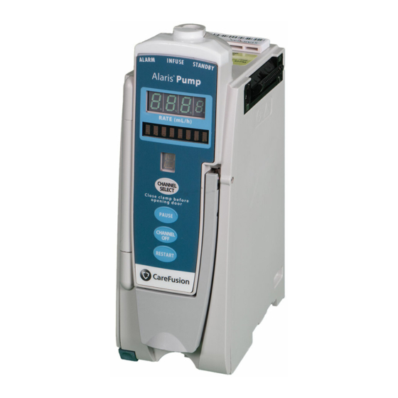
RA TE (mL/h)
PULSE (BPM)
CHANNEL
SELECT
CHANNEL
PAUSE
SELECT
CHANNEL
MONITOR
OFF
RESTART
CHANNEL
OFF
User Manual
SILENCE
OPTIONS
1
2
4
5
7
8
0
CLEAR
Alaris PC
®
®
Guardrails
RA TE (mL/h)
CHANNEL
SELECT
PAUSE
CHANNEL
SYSTEM
OFF
ON
RESTART
3
6
9
ENTER
CANCEL
February 2017
RA TE (mL/h)
CHANNEL
SELECT
PAUSE
CHANNEL
OFF
RESTART
Advertisement
Chapters
Table of Contents
Troubleshooting


Need help?
Do you have a question about the Alaris 8015 and is the answer not in the manual?
Questions and answers