
Related Manuals for CareFusion Alaris 8600

Summary of Contents for CareFusion Alaris 8600
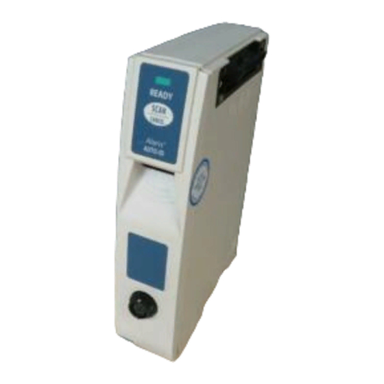
- Page 1 Technical Service Manual Alaris Auto-ID Module, Model 8600 ® Supports: Guardrails Suite MX ® November 2010 READY SCAN CANCEL...
- Page 2 Order Numbers: Printed Copy:12207531 © 2007, 2010 CareFusion Corporation or one of its subsidiaries. All rights reserved. Alaris® and Guardrails® are registered trademarks of CareFusion Corporation or one of its subsidiaries. All other trademarks belong to their respective owners. Alaris Auto-ID Module ®...
-
Page 3: Table Of Contents
Table of Contents Chapter 1 – General Information Introduction ............................Chapter 2 – Checkout and Configuration Introduction ............................New Instrument Checkout ....................... Configuration Options and Setup ....................Chapter 3 – Preventive Maintenance Introduction ............................Cleaning ............................Chapter 4 – Principles of Operation Introduction ............................ - Page 4 Table of Contents Chapter 7 – Illustrated Parts Breakdown Introduction ............................Illustrations ............................Parts List ............................Ordering Parts ..........................Figures Block Diagram ..........................Communications Boards - Model 8000 ................... Front Case Assembly ........................IUI Bracket and Board Assemblies - Camera/Frame Assembly ............Board/Frame Assembly - Front Case Assembly ................
-
Page 5: Chapter 1 - General Information
Any attempt to service this product by anyone CareFusion authorized service personnel. other than an authorized CareFusion Service Refer to the "Warranty" and "Service Representative, while the product is under Information" sections in the Alaris System ®... -
Page 6: Defined Terms
General Information Table 1-1 Defined Terms The following table identifies the defined terms used throughout this document for certain trademarked products and product features. Product / Feature defined Term Alaris Auto-ID module Auto-ID Module ® Alaris PCA module PCA Module ®... -
Page 7: Chapter 2 - Checkout And Configuration
Prior to placing a new instrument in use, perform a check-in procedure using the applicable maintenance software. Contact CareFusion authorized service personnel if the instrument has physical damage or fails to satisfactorily pass the check-in test. COnFIGuraTIOn OPTIOnS and... - Page 8 Checkout and Configuration THIS PAGE INTENTIONALLy LEFT BLANK Alaris Auto-ID Module ® Technical Service Manual...
-
Page 9: Chapter 3 - Preventive Maintenance
Chapter 3 – Preventive Maintenance InTrOduCTIOn warnInG Perform regular and preventive maintenance Failure to perform regular and preventive inspections to ensure that the Auto-ID maintenance inspections may result in improper Module remains in good operating condition. instrument operation. • Perform regular inspections before each use. - Page 10 Preventive Maintenance THIS PAGE INTENTIONALLy LEFT BLANK Alaris Auto-ID Module ® Technical Service Manual...
-
Page 11: Chapter 4 - Principles Of Operation
Service Manual for Alaris System principles ® of operation. PrInCIPleS OF OPeraTIOn Circuit boards are not field repairable and must be returned to a CareFusion Service Center for repair. 4.2.1 led (ready Indicator) A green on the front panel lights... -
Page 12: Handheld Scanner Connection
Principles of Operation 4.2.4 handheld Scanner Connection CareFusion offers a handheld scanner that can be connected to the front panel of the Auto-ID Module. The Auto-ID Module is designed for use only with handheld scanners supplied by CareFusion. 4.2.5 Speaker The speaker provides audible confirmation of key presses and successful scans. -
Page 13: Block Diagram
Principles of Operation Figure 4-1 Block diagram Camera Cable Camera Assembly Harness Keypad Harness Logic Board Keypad Logic/IUI Internal External Cable Cable Handheld Connection IUI Board Speaker Cable Speaker Left IUI Right IUI Connector Connector Alaris Auto-ID Module ® Technical Service Manual... - Page 14 Principles of Operation THIS PAGE INTENTIONALLy LEFT BLANK Alaris Auto-ID Module ® Technical Service Manual...
-
Page 15: Chapter 5 - Corrective Maintenance
The circuit boards and surface mount by qualified personnel using proper grounding devices are not field repairable. Return techniques. circuit boards to an authorized CareFusion Service Center for repair. Attempting circuit board repairs voids all warranties. CauTIOn For replacement part information, see the... -
Page 16: Required Materials, Supplies And Tools
Corrective Maintenance dISaSSeMBly/reaSSeMBly (Continued) Table 5-1 required Materials, Supplies and Tools nOTe: Contact/source information is subject to change. • Silicone Grease, Dow Corning Molykote , or equivalent (www.dowcorning.com) • Small Diagonal Cutter • Phillips Screwdrivers • Nut Drivers • Cotton Swabs • Isopropyl Alcohol • Torque Screwdriver with a minimum range of in-lbs. Recommend torque screwdriver, Micro- Adjustable, TT #844SC5002 TT #304TO034... -
Page 17: Latch Assembly And Feet
Corrective Maintenance dISaSSeMBly/reaSSeMBly (Continued) 5.2.1 latch assembly and Feet during reassembly: Apply thin layer of silicone grease to Feet Remove screws ( ) attaching Latch before insertion. Feet press-fit into module. Assembly to bottom of Rear Case. Remove Latch Assembly components from bottom of Rear Case. -
Page 18: Iui Connectors And Case Separation
Corrective Maintenance dISaSSeMBly/reaSSeMBly (Continued) 5.2.2 IuI Connectors and Case Separation during reassembly: • Ensure ground clips are still installed on Remove screws ( ) attaching each both Connectors. (left and right) to module. • To install Right Connector Gasket, Remove Connectors and Gaskets. remove protective backing and adhere to Remove screws ( ) and associated Connector. - Page 19 Corrective Maintenance dISaSSeMBly/reaSSeMBly (Continued) 5.2.2 IuI Connectors and Case Separation (Continued) IUI Connector, Left IUI Gasket IUI Connector, Right IUI Seal Silicone Tubing Front Case assembly Alaris Auto-ID Module ® Technical Service Manual...
-
Page 20: Speaker Assembly
Corrective Maintenance dISaSSeMBly/reaSSeMBly (Continued) 5.2.3 Speaker assembly during reassembly: Speaker Assembly snaps into place when Disconnect Speaker Assembly cable installed into Front Case. from Logic Board Remove Speaker Assembly from Front Case. Logic Board Speaker Assembly Alaris Auto-ID Module ® Technical Service Manual... -
Page 21: Camera/Frame/Board Assembly
Corrective Maintenance dISaSSeMBly/reaSSeMBly (Continued) 5.2.4 Camera/Frame/Board assembly during reassembly: • When reattaching keypad ground wire, Remove nut attaching keypad ground route wire to avoid pinching. wire to IUI Bracket. • When reconnecting cables to Logic Disconnect from Logic Board: Board, use an orange stick or similar tool • Internal Cable - to ensure cables are securely seated into • LED Harness - connectors. - Page 22 Corrective Maintenance dISaSSeMBly/reaSSeMBly (Continued) 5.2.5 IuI Bracket and Board assemblies during reassembly: • : Ensure Jumper Cable and : If the Jumper Cable, Camera/ IMPOrTanT IMPOrTanT cable's connectors on Logic Board and Frame Assembly or Logic Board needs to Camera Board all have same contact be replaced, identify the connector contact material.
- Page 23 Corrective Maintenance dISaSSeMBly/reaSSeMBly (Continued) 5.2.5 IuI Bracket and Board assemblies (Continued) Logic/IUI Cable Jumper Cable Frame (reference) IUI Board Logic Board Snap Rivet (2 PL) IUI Bracket Camera Board (reference) Alaris Auto-ID Module ® Technical Service Manual...
-
Page 24: Internal Cable (Handheld Connector) And Lens
Corrective Maintenance dISaSSeMBly/reaSSeMBly (Continued) 5.2.6 Internal Cable (handheld Connector) during reassembly: and lens When installing Gasket, ensure it is positioned within window frame. Use a socket wrench to remove Internal Cable nut from inside Front Case When installing Lens: Assembly. a. -
Page 25: Torque Values
Corrective Maintenance Table 5-2 Torque Values Functional application Item description Torque Value FINAL ASSEMBLy IUI Connectors 6-32 x 12 in-lb 4-40 x Latch Assembly 6 in-lb Rear Case 6-32 x 12 in-lb FRONT CASE ASSEMBLy Camera/Frame Assembly to Front Case 4-40 x 0.62 8 in-lb Internal Cable... -
Page 26: Level Of Testing Guidelines
Corrective Maintenance Table 5-3 level of Testing Guidelines Use the applicable maintenance software to perform testing. Perform = Required 8 = Optional Blank = Not Applicable Repair/Replacement of: ê Camera/Frame Assembly Front/Rear Case Assembly Internal Cable IUI Board IUI Bracket IUI Connector Latch Assembly or Feet Lens/Gasket... -
Page 27: Chapter 6 - Troubleshooting
Chapter 6 – Troubleshooting InTrOduCTIOn CauTIOn This chapter contains possible technical Class devices are safe under reasonably 1 LED problems that can occur while using the foreseeable conditions of operation, including the Auto-ID Module. See this chapter before use of optical instruments for intrabeam viewing. attempting to service the Auto-ID Module. -
Page 28: Software Compatibility
Table 6-1 Software Compatibility The software versions identified in this table were current at the time this manual was written and may change over time. Check for Service Bulletins addressing software updates or contact CareFusion Technical Support if there are any questions. -
Page 29: Communications Boards - Model 8000
Troubleshooting Figure 6-1 Communications Boards - Model 8000 Not bar code compatible. Not bar code compatible. Bar code compatible. Alaris Auto-ID Module ® Technical Service Manual... -
Page 30: Technical Troubleshooting Guide
Troubleshooting Table 6-2 Technical Troubleshooting Guide Before making a final diagnosis, visually inspect the system for damage. Following repair, use the applicable maintenance software to perform the required tests. Before returning a product (PC Unit, Auto-ID Module, handheld scanner) to the factory, replace it with a known functioning product and applicable Data Set, to verify the source of the problem. -
Page 31: Error Codes
Troubleshooting Table 6-3 error Codes If the error is repeatable, perform the response steps in the order they are listed until the error is corrected. Refer to the PC Unit/Pump Module Service Manual for more detailed error code information. Following repair, use the applicable maintenance software to perform the required tests. error Code explanation response... - Page 32 Troubleshooting THIS PAGE INTENTIONALLy LEFT BLANK Alaris Auto-ID Module ® Technical Service Manual...
-
Page 33: Chapter 7 - Illustrated Parts Breakdown
® number needed when placing an order. When a part number is not provided, that part is either not sold by CareFusion, is provided as part of a kit or higher assembly, or can only be replaced/repaired by CareFusion authorized service personnel. -
Page 34: Ordering Parts
Illustrated Parts Breakdown OrderInG ParTS Parts can be ordered by writing or calling CareFusion Customer Care (see "General Contact Information" at the beginning of this manual). When requesting a part, provide the following information: • Product name and model number (for example, Auto-ID Module, Model 8600 ) • Part number. - Page 35 Illustrated Parts Breakdown Table 7-1 Parts list nOTe: An "assembly" is a preassembled group of parts. A "kit" is a group of unassembled parts. Item Part number description TC10002944 Cable, Logic-IUI TC10004248 Cable, Internal TC10003016 Speaker Assembly TC10004794 Logic Board Assembly TC10003274 IUI Board Assembly 320851...
- Page 36 Printed Copy 10015907 Electronic (CD) Copy ---- 10012234 Auto-ID Bar Code Specification IMPOrTanT: These parts have gold contacts. Before ordering, see "Corrective Maintenance" chapter for interchangeability information. Not sold by CareFusion. Alaris Auto-ID Module ® Technical Service Manual...
-
Page 37: Front Case Assembly
Illustrated Parts Breakdown Figure 7-1 Front Case assembly (also part of 611) (also part of 611) Front Case/Keypad Assembly (part of 611) 2 PL (part of 10) Alaris Auto-ID Module ® Technical Service Manual... -
Page 38: Iui Bracket And Board Assemblies - Camera/Frame Assembly
Illustrated Parts Breakdown Figure 7-2 IuI Bracket and Board assemblies - Camera/Frame assembly Camera/Frame Assembly (part of 612) 2 PL (also part of 612) (also part of 612) Alaris Auto-ID Module ® Technical Service Manual... -
Page 39: Board/Frame Assembly - Front Case Assembly
Illustrated Parts Breakdown Figure 7-3 Board/Frame assembly - Front Case assembly To Logic Board J6 To Logic Board J11 4 PL (also part of 612) To Logic Board J5 See Figure 7-2 Alaris Auto-ID Module ® Technical Service Manual... -
Page 40: Speaker Assembly
Illustrated Parts Breakdown Figure 7-4 Speaker assembly Logic Board See Figure 7-3 Alaris Auto-ID Module ® Technical Service Manual... -
Page 41: Iui Connectors And Case Assembly
Illustrated Parts Breakdown Figure 7-5 IuI Connectors and Case assembly 2004 2 PL 2003 2 PL 2 PL 2 PL ~15½" (also part of 610) 2009 See Figure 7-3 Alaris Auto-ID Module ® Technical Service Manual... -
Page 42: Feet, Latch Assembly, Labels
Illustrated Parts Breakdown Figure 7-6 Feet, latch assembly, labels Nameplate Label, which has a regulatory mark, is not field replaceable as an individual item. It is available only as part of Rear Case Kit (item 610). 2 PL 2006 2 PL (also part of 610) Nameplate Label (also part of 610) 7-10... -
Page 43: Iui Board
Illustrated Parts Breakdown Figure 7-7 IuI Board This illustration is for board identification purposes only and does not represent the board's component layout. 7-11 Alaris Auto-ID Module ® Technical Service Manual... -
Page 44: Logic Board
Illustrated Parts Breakdown Figure 7-8 logic Board This illustration is for board identification purposes only and does not represent the board's component layout. 7-12 Alaris Auto-ID Module ® Technical Service Manual... - Page 46 Alaris Auto-ID Module ® Technical Service Manual...
Need help?
Do you have a question about the Alaris 8600 and is the answer not in the manual?
Questions and answers