
Related Manuals for JLG sky trak mmv


Summary of Contents for JLG sky trak mmv
- Page 1 TM 10794A-24/2 Model MMV OM0651 SERVICE MANUAL 8990440 PCN 500 107941 00 Printed in U.S.A. 12/04...
- Page 3 EFFECTIVITY PAGE December 17, 2004 - B - Replaced all branding with JLG. 8990440...
- Page 4 EFFECTIVITY PAGE 8990440...
-
Page 5: Table Of Contents
SECTION CONTENTS Section Subject Page Section 1 Safety Practices ............Introduction . - Page 6 Section Subject Page Section 5 Axles, Wheels and Tires ..........Axle and Wheel Component Terminology .
- Page 7 Section Subject Page 9.11 Hydraulic System Pump ..........9.87 9.12 Valves and Manifolds .
-
Page 8: Section Subject Page
Section Subject Page Model MMV Rev. 12/17... - Page 9 Section 1 Safety Practices Contents PARAGRAPH TITLE PAGE Introduction ............Owners/Operators Manual .
-
Page 10: Safety Practices
Sky Trak MMV Telescopic Material Handler. Provisions for supplementary information are made by Particular effort has been made to produce a manual to... -
Page 11: Training Mechanics As Operators
OSHA OP0330 regulations listed in the NOTICE below, and reads and understands the Sky Trak MMV Telescopic Material This symbol means “Attention! Become Alert! Your Handler Owners/Operators Manual before operating or Safety Is Involved!” The symbol is used to attract atten- maintaining the vehicle. -
Page 12: Accident Prevention Tag Usage
Safety Practices 1.4.2 Hazard Statements ACCIDENT PREVENTION TAG USAGE Signal words and messages are used in conjunction with the safety alert symbol to create hazard statements. These hazard statements convey important information about safety. Four types of hazard statements are used in this manual. Each statement indicates the existence and degree of rel- ative risk of the hazard described within the statement that follows the signal word. -
Page 13: Safety Instructions
Safety Practices SAFETY INSTRUCTIONS 1.6.2 Equipment Hazards OWNERS/OPERATORS MANUAL: Before operating Following are general safety statements to consider the vehicle, carefully read, understand and follow the before performing maintenance procedures on a vehicle. Owners/Operators Manual. Additional statements related to specific tasks and proce- OPERATIONAL PROTECTION: Before operating the ve- dures are located throughout this manual and are listed hicle or returning it for operational use, check that the op-... -
Page 14: Emergency Exit Rear Window
Safety Practices 1.6.3 General Hazards FLUID PRESSURE: Before loosening any hydraulic or diesel fuel component, hose or tube, turn engine OFF. SOLVENTS: Only use approved solvents, and solvents Wear heavy, protective gloves and eye protection. that are known to be safe for use. NEVER check for leaks using any part of your body;... -
Page 15: Hazard/Emergency Information Signs
If a replacement sign is needed, refer to the Owners/Op- erators Manual and parts catalog for the latest parts num- INFORMATION SIGNS bers and ordering information. Or, contact JLG Inc. directly at: Locations of vehicle hazard and other emergency infor- mation signs are shown below. - Page 16 Safety Practices This Page Intentionally Left Blank Model MMV Rev. 12/04...
-
Page 17: General Information, Specifications And Maintenance
Section 2 General Information, Specifications and Maintenance Contents PARAGRAPH TITLE PAGE MMV Component Terminology........Introduction . - Page 18 General Information, Specifications and Maintenance Fluids, Lubricants and Capacities ........2.20 2.6.1 Axles (Differential Housings) and Transfer Case.
- Page 19 General Information, Specifications and Maintenance 2.13 Maintenance Instructions ..........2.28 2.13.1 Maintenance Schedule and Checklist .
- Page 20 General Information, Specifications and Maintenance This Page Intentionally Left Blank Model MMV Rev. 12/04...
-
Page 21: Mmv Component Terminology
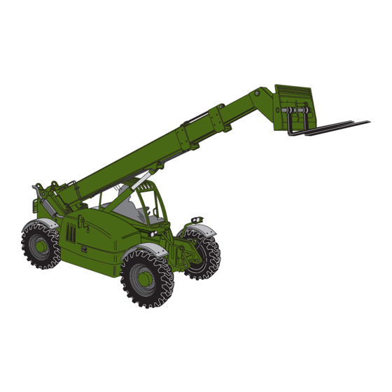
General Information, Specifications and Maintenance MMV COMPONENT TERMINOLOGY To understand the safety, operation and maintenance information presented in this manual, it is necessary that the operator/mechanic be familiar with the name and location of the major assemblies on this vehicle. The following illustration identifies the components that are referred to throughout this manual. -
Page 22: Introduction
JLG. 2.2.4 Disclaimer JLG reserves the right to make changes to and to add im- provements upon its product at any time, without public notice or obligation. JLG also reserves the right to dis- continue manufacturing any product at its discretion at any time. -
Page 23: Torques
General Information, Specifications and Maintenance TORQUES 3. Tighten fitting to the proper torque according to the following chart: 2.3.1 Fasteners Torque All fasteners (nuts, bolts, washers, etc.) are equal to SAE Size Grade 5 (PC8.8) and are plated, unless otherwise specified. lb/ft 15-17 20-23... -
Page 24: Metric Conversion Factors
General Information, Specifications and Maintenance 2.3.5 Flat-Face O-ring Fittings METRIC CONVERSION FACTORS When the vehicle leaves the factory, it is equipped only with straight thread o-ring fittings. Customer-added 2.4.1 Approximate American to Metric accessories may differ; therefore, consult the manufac- Conversions turer’s product literature for information. - Page 25 General Information, Specifications and Maintenance VOLUME AREA Teaspoons (tsp) Milliliters (ml) Square centimeters Square inches (in Tablespoons (Tbsp) 15 Milliliters (ml) Square meters (m ) 1,1 Square yards (yd Cubic inches (in Milliliters (ml) Square kilometers Fluid ounces (fl oz) Milliliters (ml) Square miles (mi Cups (c)
-
Page 26: Specifications
General Information, Specifications and Maintenance SPECIFICATIONS 2.5.1 Vehicle Dimensions With 15.50-25 Radial Tires Description Specifications (A) Length (without Forks) 248" (6.299 mm) (B) Width 101" (2.565 mm) (C) Height (Boom Lowered) 93" (2.362 mm) (D) Wheelbase 131" (3.327 mm) (E) Tread Center 84"... - Page 27 General Information, Specifications and Maintenance G & H MM2230 Model MMV Rev. 12/04 2.11...
- Page 28 General Information, Specifications and Maintenance 2.5.2 Vehicle Weights Vehicle Configuration Front Axle Rear Axle Total Without Carriage 9,250 lbs 17,650 lbs 26,900 lbs (4.196 Kg) (8.006 Kg) (12.202 Kg) With 11K Carriage 11,200 lbs 16,900 lbs 28,100 lbs (5.080 Kg) (7.666 Kg) (12.746 Kg) With 7K Carriage...
- Page 29 General Information, Specifications and Maintenance 2.5.5 Hydraulic Cylinder Performance Specifications Note: Vehicle with no load, engine at full throttle, hydraulic oil warm (80° F [27° C] minimum), engine at operating temperature Function Approximate Times, Approximate Times, in Seconds in Seconds 7K Carriage 11K Carriage Boom Extend...
- Page 30 General Information, Specifications and Maintenance 2.5.6 Electrical System Description Specifications Battery: Type, Rating 12 VDC, Negative (-) Ground, Maintenance Free Quantity Reserve Capacity 1225 Cold Cranking amps @ 0° F (-18° C) Group/Series HASP-FT Alternator 24V/70 amps Fuses - Standard Blade Style: Switch Lamps, Service Brake, Hourmeter 2 amps LMI System...
- Page 31 General Information, Specifications and Maintenance 2.5.7 Engine Performance Specifications Note: Engine manufacturer's maximum “high idle” setting is lockwired and sealed. DO NOT disturb this setting. Description Specifications Engine Make/Model Cummins Turbo/4BTA3.9 Displacement 239 in (3.9 liters) Horsepower 116 HP @ 2500 rpm Number of Cylinders Engine High Idle with No Load 2750 ±100...
- Page 32 General Information, Specifications and Maintenance 2.5.8 Fluid and Lubricant Capacities Fluid & Lubricant Description Specifications Engine Crankcase Oil: Capacity with Filter Change 13.3 qt (12,6 liters) Filter Capacity 1.3 qt (1,2 liters) Oil Type Above 23° F (-5° C) use SAE 15W40 Diesel Engine Oil. (Refer to Section 2.6.5, Engine .) 23°...
- Page 33 General Information, Specifications and Maintenance Fluid & Lubricant Description Specifications Axle (Wheel Ends): Capacity 1.3 qt (41.6 fl oz, or 1,2 liters) Type of Oil Above 100° F (38° C) use MIL-PRF-2104G Grade 15W40 (Refer to Section 2.6.1, Axles (Dif- Below 100°...
- Page 34 General Information, Specifications and Maintenance 2.5.10 Tires Description Specifications Tire Size 15.5R25, L-2, (2 Star Minimum) Radial Wheel Lug Nut Torque 430-470 lb/ft (583-637 Nm) Air Pressure 87 psi (600 kPa) Tire Footprint Area (area is established under max. tip load): Vehicle with 7K Carriage with No Load 126 in (810 cm...
- Page 35 General Information, Specifications and Maintenance 2.5.12 Tamper Proofing WARNING: A tamper-proof means is in place on the following DO NOT exceed the adjustable components prior to machine shipment. This total rated capacity of the specific pair of forks can either be tamper-proof paint, or a steel tamper-proof being used.
-
Page 36: Fluids, Lubricants And Capacities
General Information, Specifications and Maintenance FLUIDS, LUBRICANTS AND 2.6.2 Wheel Ends CAPACITIES a. Wheel-End Lubricants Recommended Oil/Temperature Range 2.6.1 Axles (Differential Housings) and Transfer Case a. Axle and Transfer Case Lubricants MIL-PRF-2104G Grade 15W40 Recommended Oil/Temperature Range MIL-PRF-2104G Grade 10W30 (Universal Tractor Fluid*) 100°... -
Page 37: Lubrication Points (Grease Fittings)
General Information, Specifications and Maintenance 2.6.3 Lubrication Points (Grease Fittings) 2.6.5 Engine Lubricants a. Engine Fluids and Lubricants When lubricating any component via the grease fittings, use multi-purpose lithium-based grease with EP additives 1. Engine oil: that meets NLGI Grade 2 specifications. Products known to meet these requirements include: Recommended Oil/Temperature Range •... -
Page 38: Transmission
General Information, Specifications and Maintenance b. Engine Capacities 2.6.7 Air Conditioning 1. Engine Oil Capacity a. Air Conditioning Fluid Capacity w/filter change ....13.3 qt (12,6 liters) Type ..............R134a Filter............1.3 qt (1,2 liters) b. Air Conditioning System Capacity 2. -
Page 39: General Anti-Corrosion
General Information, Specifications and Maintenance 2.6.9 General Anti-Corrosion 2.6.11 Paint Unless otherwise specified, paint components as indicat- a. Anti-Corrosion Compound ed in the following sections. For general anti-corrosion protection, use a wax film rust inhibitor that provides a protective film two ten- a. -
Page 40: Cleaning
General Information, Specifications and Maintenance CLEANING HOSES AND TUBES Dirt and abrasive dust reduce the efficient working life of 2.9.1 Hose and Tube Inspection parts and systems, and lead to the costly replacement of components. To help increase the service life of parts, 1. -
Page 41: Bearings
General Information, Specifications and Maintenance 2.10 BEARINGS 2.11 PRESSURE TESTING AND ADJUSTMENT 2.10.1 Bearing Removal Prior to pressure testing or adjustment, verify that all hos- 1. NEVER remove bearings unless absolutely es and tubes are in good condition and that all fittings are necessary! Always use the recommended puller to tight. - Page 42 4. Refer to the ZF 4 WG-98 TS Transmission Repair 5. Check for brittle or frayed wire shielding. Manual (ZF part number 5871 139 002, JLG part 6. Connect the negative (-) battery cable terminal to the number 8990418) for servicing the transmission battery (if it is disconnected).
- Page 43 General Information, Specifications and Maintenance 12. Recheck the level of fluid in the transmission with the engine running at idle. 13. Add oil as necessary to bring the fluid level up to the FULL mark on the transmission dipstick. Install the oil dipstick.
-
Page 44: Maintenance Instructions
Compressor Intake Filter Wear Pads cause death or serious injury. MM3211 IMPORTANT: JLG recommends the use of environmen- At ten-hour intervals, perform the following: tally sound waste storage and disposal practices. • Drain the fuel/water separator (refer to Section NEVER drain fluids on the ground or into a sewer or 2.13.7, Engine Fuel System ). - Page 45 General Information, Specifications and Maintenance b. At First 50 Hours of Use • Check the wheel end oil level (refer to Section 2.13.13, Wheel End Oil ). • Inspect Extend Chains (refer to Section 2.13.21, Boom Chain Tension & Adjustment ). •...
-
Page 46: Air Cleaner
General Information, Specifications and Maintenance d. 500 Hour Intervals 2,000 Hour Intervals Change Change Change Engine Fuel Coolant Filter Filter MT00701 MS1380 At 500 hour intervals, perform the following: At 2,000 hour intervals, perform the following: • Change the air filter (refer to Section 2.13.2, Air •... - Page 47 General Information, Specifications and Maintenance Outer Primary Element 4. If replacing the inner element (8) at this time, carefully slide the element out. Always discard this All air cleaner manufacturers agree that attempting to element and replace with a new element. clean or wash an element increases the chance for ele- 5.
-
Page 48: Closed Cab Air Filters
General Information, Specifications and Maintenance 2.13.3 Closed Cab Air Filters Fresh Air Intake Filter The closed cab has two air filters, the recirculation air fil- Periodically remove the cab rear panel and inspect the ter and the fresh air intake filter. Both of these filters re- fresh air intake filter (7). -
Page 49: Engine Cooling System
General Information, Specifications and Maintenance 2.13.4 Engine Cooling System b. Drain and Flush the Radiator a. Engine Coolant Level Check (10 Hour Intervals) 2000 MS3000 OS0810 MS21402 OS0800 1. Level the vehicle, ground the attachment, place the 1. Level the vehicle, ground the attachment, place the travel select lever in the [N] NEUTRAL position, place travel select lever in the [N] NEUTRAL position, place the neutral lock lever in the [N] NEUTRAL LOCK... - Page 50 General Information, Specifications and Maintenance 4. Slowly turn the radiator cap (1), located in the upper 9. Transfer the coolant to a container with a cover and radiator hose, to the first stop and allow any label the container “Used Anti-freeze.” Dispose of the pressure to escape.
-
Page 51: Engine Oil And Filter
General Information, Specifications and Maintenance 2.13.5 Engine Oil and Filter b. Oil Level Check a. Engine Oil Recommendations The use of quality engine oil combined with the appropri- ate oil and filter change intervals are critical factors in maintaining engine performance and durability. (Refer to the chart below for recommended oil types for various op- MS21402 OS0820... - Page 52 General Information, Specifications and Maintenance c. Oil and Filter Change 7. Allow the oil to drain completely into the receptacle. Transfer the oil to a container with a cover and label the container as used motor oil. Dispose of used oil at an approved recycling facility.
-
Page 53: Engine Oil Sample Point
General Information, Specifications and Maintenance 2.13.7 Engine Fuel System a. Drain Water from Fuel-Water Separator/Filter MS21402 OS0851 1. Level the vehicle, ground the attachment, place the travel select lever in the [N] NEUTRAL position, place the neutral lock lever in the [N] NEUTRAL LOCK MM4570 position, engage the parking brake switch and shut the engine OFF. - Page 54 General Information, Specifications and Maintenance b. Change Fuel Filter c. In-line Fuel Strainer MS21802 OS0870 MS21802 OS0870 Change the fuel filter every 500 hours of engine opera- 1. Level the vehicle, ground the attachment, place the tion, or at shorter intervals with water evidence of con- travel select lever in the NEUTRAL [N] position, place taminated fuel.
- Page 55 General Information, Specifications and Maintenance 5. Remove and properly dispose of the old strainer. WARNING: 6. Install the new strainer with the arrow pointing Diesel fuel under pres- toward the lift pump. sure can penetrate the skin and cause serious 7.
-
Page 56: Engine Fan Belt & Air Conditioner Compressor Belt
General Information, Specifications and Maintenance 2.13.8 Engine Fan Belt & Air Conditioner Compressor Belt MS21902 OS0880 a. Engine Fan Belt 1. Ground the attachment, place the travel select lever in the [N] NEUTRAL position, place the neutral lock lever in the [N] NEUTRAL LOCK position, engage the parking brake switch and shut the engine OFF. -
Page 57: Hydraulic System Oil And Filter
General Information, Specifications and Maintenance Recommended Hydraulic Oil/Temperature Range MIL-PRF-2104G Grade 10 DEXRON lll (Automatic Transmission Fluid) 14° F (-10° C) 125° F (50° C) OM1700 5. DO NOT add oil through the hydraulic oil tank breather (14) located beside the suction hose fitting. MM4570 2.13.9 Hydraulic System Oil and Filter... - Page 58 General Information, Specifications and Maintenance b. Hydraulic Oil and Hydraulic Oil Filter Change 3. Place an Accident Prevention Tag on both the ignition switch and steering wheel, stating that the vehicle should not be operated. (Refer to Section 1.5, Accident Prevention Tag Usage .) 4.
-
Page 59: Transmission Oil And Filter
General Information, Specifications and Maintenance 13. If the hydraulic oil return line was swiveled out of the 2.13.10 Transmission Oil and Filter way, reposition the line. If the indicator wiring was unplugged, reconnect it. a. Transmission Oil Level Check 14. Remove the fill cap (4) and fill with hydraulic oil until the oil level is visible within the lower end of the sight glass (10). - Page 60 General Information, Specifications and Maintenance b. Transmission Oil and Filter Change 8. Transmission oil may be added through the dipstick tube (3). Remove the dipstick and fill with approximately 12 quarts (11,4 liters) of oil (see the following chart for oil recommendations). Check the level by taking intermittent dipstick readings as outlined in Transmission Oil Level Check.
-
Page 61: Axle Oil
General Information, Specifications and Maintenance 2.13.11 Axle Oil a. Axle Oil Level Check MS21702 OT0460 1. Level the vehicle, ground the attachment, place the travel select lever in the [N] NEUTRAL position, place the neutral lock lever in the [N] NEUTRAL LOCK OT02702 position, engage the parking brake switch and shut the engine OFF. -
Page 62: Brake Disc Wear Check
(10,0 liters). the ZF Axle Repair Manuals, Model MS-T 3060, front axle with parking brake (ZF part # 5871 560 002, JLG part # 10. Reinstall the axle fill and level plugs (2 and 3) into 8990430) or Model MS-T 3045, rear axle without parking the axle housing using new o-rings. - Page 63 General Information, Specifications and Maintenance 5. Use the handle (5) on the emergency towing valve to pump pressure into the system. Watch the pressure gauge (6) while pumping pressure into the park brake system. DO NOT exceed 650 psi (45 bar). CAUTION: DO NOT exceed 650 psi (45 bar) when pressurizing the park brake.
-
Page 64: Wheel End Oil
General Information, Specifications and Maintenance 2.13.13 Wheel End Oil WARNING: DO NOT perform ser- vice or maintenance on this vehicle with the engine running. Contact with moving parts can cause death or serious injury. a. Wheel End Oil Level Check OT02802 b. -
Page 65: Transfer Case Oil
General Information, Specifications and Maintenance 7. Fill the wheel end with oil. Refer to the recommended wheel end oil/temperature range on page 2.48 for proper oil to use. The wheel end is full when the oil is level with the bottom of the plug hole. Wheel end oil capacity is approximately 1.3 quarts (1,2 liters). -
Page 66: Wheels And Tires
General Information, Specifications and Maintenance 2.13.15 Wheels and Tires c. Replacing Tires a. Tire Pressure Check WARNING: Mis-matched tire sizes and PLY ratings may compromise vehicle sta- bility and may result in vehicle tipover. IMPORTANT: The specified size and ply rating for this vehicle is 15.5R25, L-2, 2 Star. - Page 67 25 cleanings or if damaged. To clean and recharge the filter you will need a filter cleaner/recharger kit. The kit can be ordered by calling JLG at (717) 458-5161 domestically or (877) 554-5438 internationally. This kit contains a 12 oz bottle of filter OM1590 cleaner and a 6.5 oz spray can of oil.
- Page 68 General Information, Specifications and Maintenance d. Drain Water From Emergency Tire Inflation Tank e. Tire Inflation The tire inflation system will enable the tires on this vehi- cle to be inflated to the proper air pressure without going back to a maintenance area. 1.
- Page 69 General Information, Specifications and Maintenance 4. The air storage tank (2) is located at the front 7. Enter the operators cab and start the engine. underside of the operators cab. 8. Exit the cab and inflate the tire or tires to the proper 5.
-
Page 70: Batteries
General Information, Specifications and Maintenance 2.13.17 Batteries WARNING: Fluid (electrolyte) in a. Batteries Inspection, Testing and Service electric storage batteries contains sulfuric acid, a POISON that can cause SEVERE CHEMI- WARNING: CAL BURNS. Avoid all contact of fluid with Lead-acid batteries pro- eyes, skin or clothing. - Page 71 General Information, Specifications and Maintenance b. Battery Charging WARNING: DO NOT charge a fro- zen battery. A frozen battery could explode and cause death or serious personal injury. Allow the battery to thaw before “slave starting” the vehicle or connecting a battery charger. Under normal operating conditions, the alternator will keep the batteries charged.
-
Page 72: Fuse And Relay Replacement
General Information, Specifications and Maintenance 2.13.18 Fuse and Relay Replacement IMPORTANT: Shut off the engine and follow the battery disconnect procedure below, before checking the electri- cal system. Use an ohmmeter to check the resistance of wires and components. a. Disconnect Batteries 1. - Page 73 General Information, Specifications and Maintenance Before checking a malfunctioning electrical circuit, c. Fuses, Relays and Circuit Breaker examine the applicable wiring diagram (refer to Section (Right Side Dash) 10, Electrical System ) to help identify the components There is a separate fuse holder under the right side of the involved.
- Page 74 General Information, Specifications and Maintenance There is one circuit breaker (1) located under the right side of the dash that protects the keyless ignition circuit. It is mounted to the side of the steering column mount just below the flasher. This circuit breaker will trip if there is a short or grounded wire in the applicable circuit.
- Page 75 General Information, Specifications and Maintenance Unlatch and open the rear door. The relay is mounted to the fan shroud. Remove the protective cover (23) from the fuse holder (24) to gain access to the 15 amp fuse. OM1570 There is one relay (18) located behind the battery equalizer mounting bracket (19).
-
Page 76: Boom Wear Pad Maintenance
General Information, Specifications and Maintenance 2.13.19 Boom Wear Pad Maintenance The boom wear pads that are under the most stress from weight of the load will also wear faster than other pads. For example, the lower pads at the front of the boom are under much more stress than the pads attached at the top front or sides of the boom. -
Page 77: Boom Chain Inspection
General Information, Specifications and Maintenance 2.13.20 Boom Chain Inspection Dynamic shock loading can impose abnormal loads above the endurance limit of a leaf chain. • High velocity movement of load, followed by sudden, abrupt stops. • Carrying loads in suspension over irregular surfaces such as railroad tracks, potholes, and MS21702 rough terrain. - Page 78 General Information, Specifications and Maintenance Elongation Edge Wear When the original length (1) of 12.00" (305 mm) per Check the chain for wear on the link plate edges foot of new chain has elongated from wear to a caused by running back and forth over the sheave. length (2) of 12.36"...
- Page 79 General Information, Specifications and Maintenance Turning or Protruding Pins • Fatigue Cracking - Fatigue cracks (8) are a result of repeated cyclic loading beyond the Highly loaded chain, operating with inadequate lubri- chain’s endurance limit. The size of the load and cation can generate abnormal frictional forces be- the frequency of its occurrence are factors which tween pin and link plates.
-
Page 80: Boom Chain Tension & Adjustment
General Information, Specifications and Maintenance Other Modes of Failure 2.13.21 Boom Chain Tension & Adjustment • Ultimate Strength Failure - These types of a. Boom Chain Tension Check failures are caused by overloads far in excess of the design load. Either fractured plates (1) or enlarged holes (2) can occur. - Page 81 Then with the boom horizontal, retract may require extensive adjustment and/or repair. the boom completely. Turn the engine OFF. Contact the JLG Service Department or the nearest 8. Recheck the measurement (6) at the rear of the JLG Authorized Service Center (ASC).
- Page 82 General Information, Specifications and Maintenance 9. Start the vehicle, cycle the boom in and out several 2. Adjust the top extend boom chains by tightening the times. With the boom horizontal, fully extend the locknuts (3), located at the rear of the boom (4). Be boom and then retract it 2"...
-
Page 83: Chain Lubrication
(“LUBRIPLATE” Chain & Cable Fluid, “LPS3” or boom may require extensive adjustment and/or repair. equivalent). Contact the JLG Service Department or the nearest JLG The lubricant must penetrate the chain joint to prevent Authorized Service Center (ASC). wear. Applying lubricant to the external surfaces will... -
Page 84: Short Term Storage
Sky Trak MMV required. Telescopic Material Handler Owners/Operators 8. If the ambient temperature is expected to remain Manual. - Page 85 General Information, Specifications and Maintenance 4. Coat the tires with a anti-ozone protectant coating. b. Removing Vehicle from Storage One of the recommended coatings is #G9588 “Black After removing the vehicle from storage and before Rubber Preservative” from the Akron Paint and operating it, perform the following steps: Varnish Company.
-
Page 86: Counterweight Removal And Reassembly
Note: Record the number of flat washers on each cap- operator with all the safe and proper operating screw as they are removed. The correct number of flat procedures contained in the Sky Trak MMV washers must be reassembled in the same locations to Telescopic Material Handler Owners/Operators ensure proper capscrew protrusion during reassembly of Manual. - Page 87 General Information, Specifications and Maintenance b. Assembly IMPORTANT: When applying the Loctite® threadlocker to the threads of the bushing and the capscrews you have a maximum of ten minutes to line the counterweight up and insert all four capscrews. The threadlocker will start to set-up after ten minutes.
-
Page 88: Transport
General Information, Specifications and Maintenance 2.13.26 Transport When transporting the vehicle, make use of all tiedown/ ing the weight of the vehicle being transported and that all manufacturer’s instructions and warnings, regulations lift point locations on the vehicles frame. and safety rules of their employer, the Department of Note: The user assumes all responsibility for choosing Transportation and/or any other state or federal laws are the proper method of transportation, and the proper... - Page 89 General Information, Specifications and Maintenance a. Truck Transportability MIRROR TO BE ROTATED INWARD MIRROR TO BE ROTATED INWARD 93.6" (2377 mm) MAX HEIGHT 100.2" (2545 mm) MAX WIDTH STANDARD 96" COMMERCIAL 54" (1372 mm) TRAILER SHOWN OM1251 b. Rail Transportability and GIC Clearance NORTH AMERICAN NATO GIC RAIL TRANSPORT...
- Page 90 General Information, Specifications and Maintenance c. Air Transport, C-17, C141 or C-5 Tiedowns 111" (2819 mm) 103" (2616 mm) 103" (2616 mm) FS 734, 958, 998 & 1058 AFT OPENING DESIGN LIMITS 103" (2616 mm) 111.25" (2826 mm) MAXIMUM TYPICAL SECTION OM1280 Axle and Tire Data Axle...
- Page 91 General Information, Specifications and Maintenance d. Air Transport, C-130 Configuration CLEARANCE ENVELOPE SAFETY AISLE BOTH MIRRORS TO BE ROTATED IN For axle and pallet weights refer to the follow- 102" ing tables. (2591 mm) Axle and Tire Data Axle Rear Front 11,100 lbs 12,200 lbs...
- Page 92 General Information, Specifications and Maintenance e. Marine Transportability APPROX. 45° OM1331 External Transport/Slinging Tilt Carriages Weight Distance Angle 67.25" 30,500 lbs CH-53 Both Carriages 2.0° (1708 mm) (13.835 Kg) Not Allowed (7 K) 48" Load 73.25" 29,300 lbs CH-53 5.0° Center Carriage (1860 mm) (13.290 Kg)
-
Page 93: Emergency Operations
Contact your local JLG Authorized Service Center (ASC) or the JLG Service Department at (877) 554-5438 for specific instructions for your particular situation. If it is necessary to tow the vehicle a short distance to... -
Page 94: Towing A Disabled Vehicle Long Distances
WARNING: basis. Contact your local JLG Authorized Service Center Always disconnect the (ASC) or the JLG Service Department at (877) 554-5438 steer cylinder crossover hoses before resum- for specific instructions for your particular situation. ing normal operation. Failure to disconnect the... - Page 95 General Information, Specifications and Maintenance 9. Use the handle (10) on the emergency towing valve to pump pressure into the system. Watch the WARNING: BLOCK ALL FOUR pressure gauge (11) while pumping pressure into WHEELS. Failure to do so could result in the park brake system.
-
Page 96: Boom Lowering And Retracting
IMPORTANT: In the event of total loss of engine power or hydraulic pump failure with an elevated load, properly evaluate and deal with each situation on an individual basis. Contact the nearest JLG Authorized Service Cen- ter (ASC) or the JLG Service Department for specific instructions. OM1080 2.80... -
Page 97: Parking Brake/Transmission De-Clutch Test Procedures
With the parking brake applied, move the range 4. Service the parking brake immediately or contact select lever to [1] FIRST gear. your local JLG Authorized Service Center (ASC) to repair the system. f. Move the travel select lever to [F] FORWARD. - Page 98 General Information, Specifications and Maintenance This Page Intentionally Left Blank 2.82 Model MMV Rev. 12/04...
-
Page 99: Cab, Covers And Mirrors
Section 3 Cab, Covers and Mirrors Contents PARAGRAPH TITLE PAGE Operator’s Cab and Covers Component Terminology..... Operator’s Cab........... . . 3.2.1 Operator’s Cab Description . -
Page 100: Operator's Cab And Covers Component Terminology
Cab, Covers and Mirrors OPERATOR’S CAB AND COVERS COMPONENT TERMINOLOGY To understand the safety, operation and maintenance in- formation presented in this section, it is necessary that the operator/mechanic be familiar with the name and lo- cation of the major assemblies of the vehicle cab and cov- ers. -
Page 101: Operator's Cab
Cab, Covers and Mirrors To help ensure optimum safety, protection and perfor- WARNING: DO NOT service the mance, replace the cab if it is damaged. Refer to the vehicle without following all safety precautions appropriate parts manual for ordering information. as outlined in the “Safety Practices”... -
Page 102: Cab Maintenance
Inspect the cab, its welds and mounts. If modification, damage, a cracked weld and/or fatigued metal is discov- ered, replace the cab. Contact the JLG Service Depart- ment or the local JLG Authorized Service Center (ASC) with any questions about the suitability or condition of a cab. - Page 103 Cab, Covers and Mirrors 11. Remove two capscrews (17), lockwashers (18) and rebound washers (19) from the rear of the cab (20). 12. Open the armrest (21) and remove capscrew (22), lockwasher (23) and rebound washer (24) securing the rear tool bin (34) to the console support (25). 13.
- Page 104 Cab, Covers and Mirrors 17. Remove the three self-drilling screws (1) (one screw 20. Remove the four button head screws (7) from the is not visible in illustration) securing the lower dash display panel (8) in the front dash. Carefully pull cover (2) to the front dash (3).
- Page 105 Cab, Covers and Mirrors MM4250 MM2170 29. Label and disconnect the wires (28) connected to 24. Pull out switch banks (15 and 16), located to the left the ignition switch (29). Remove the screws (30) and and right of the steering column, and hazard switch (17), above and to the right of the display panel external tooth lockwashers (31) securing the wires to opening.
- Page 106 Cab, Covers and Mirrors 30. Remove capscrew (1), lockwasher (2), and flat washer (3) securing the lower left corner of the front dash panel to the cab. 31. Working from the underside of the dash, remove the two capscrews (4), lockwashers (5), and rebound washers (6) securing the dash panel (7) to the cab.
- Page 107 Cab, Covers and Mirrors MM4650 35. Label, disconnect and cap the four steering valve hoses (12-15). 36. Label, disconnect and cap the five hoses (23 and 24) connected to the brake valve (25). Access the MM4620 three top hoses (23) through the display panel opening in the dash.
- Page 108 Cab, Covers and Mirrors 37. Remove the three capscrews (1), lockwashers (2) and flat washers (3) holding the throttle pedal (4) to the floor of the cab. Save all the hardware for reassembly. SS1960 MM2940 38. Remove elastic locknut (5). Disconnect the throttle cable rod end (6) at the throttle lever extension 40.
- Page 109 Cab, Covers and Mirrors 45. Route the joystick, power steering and service brake hydraulic hoses out of and away from the cab. Cut and dispose of plastic wire ties as needed. Wipe up any spilled hydraulic fluid. 46. Remove the elastic locknut (24) and disconnect the ground strap (25).
- Page 110 Cab, Covers and Mirrors 49. From behind the cab, loosen the lower clamp (1) 54. Remove the front cab to cab mount attaching hardware. securing the fuel hose (2) to the fuel tank (3). Remove two capscrews (10), and rebound washers Remove the lower end of the fuel hose from the fuel (11) from the cab isolators (12).
- Page 111 Cab, Covers and Mirrors 58. Carefully begin to lift the cab. Stop and check that all wiring, fuel tank components, hydraulic hoses and fasteners are disconnected or removed. If the throttle cable is still attached to the cab, reposition or remove the throttle cable as necessary.
- Page 112 Cab, Covers and Mirrors c. Cab Installation 2. Attach a clevis (1 and 2) to each of the cab lifting brackets. Route a sling (3) with a minimum lifting capacity of 2,000 lbs. (907 kgs.) through the clevis’ WARNING: Cap or safely cover the to a hoist or overhead crane.
- Page 113 Cab, Covers and Mirrors 7. Install the rear cab to cab mount attaching hardware. 9. From behind the cab, position the lower clamp (12) Install but DO NOT tighten two 3/4-10 x 3-3/4" on the fuel hose (13). Remove any cap or safety capscrews (7), two rebound washers (8) and two cover from the fuel tank opening.
- Page 114 Cab, Covers and Mirrors 14. Route the joystick, power steering and service brake hydraulic hoses from the frame into the cab. 15. From beneath the cab, route and connect all wiring (engine, lighting harnesses and all leads from the cab harness). Install plastic conduit as required to protect the wiring as it passes through metal openings.
- Page 115 Cab, Covers and Mirrors Note: ALWAYS use new o-rings when servicing the vehicle. 26. Install new o-rings into the fittings. Lubricate the o-rings with clean hydraulic oil. 27. Install the five hoses (30 and 31) to the brake valve (32). Access the three top hoses (30) through the display panel opening in the dash.
- Page 116 Cab, Covers and Mirrors Note: ALWAYS use new o-rings when servicing the vehicle. 28. Install new o-rings into the fittings. Lubricate the o-rings with clean hydraulic oil. 29. Connect the four steering valve hoses (1-4). MM4680 MM4650 32. With the dash panel (19) tipped into the cab, route 30.
- Page 117 Cab, Covers and Mirrors 33. Route the flexible hose (23) from the lower tube on the vent manifold up to the right side of the dash. Push the flexible hose onto the retainer half of the ball vent (24) and secure in place with a tie wrap (25).
- Page 118 Cab, Covers and Mirrors 40. Connect the transmission selector switch wiring connector (1), turn signal/lights lever wiring connectors (2) and brake switch connector (3). MM2170 43. Working through the display panel opening, connect the hourmeter wiring connectors to the hourmeter (8). MT1890 41.
- Page 119 Cab, Covers and Mirrors 50. Open the armrest (26) and install one 5/16-18 x 2" capscrew (27), 5/16" lockwasher (28), and rebound washer (29) securing the rear tool bin to the console support (30). 51. Install two 5/16-18 x 1-3/4" capscrews (31), 5/16" lockwashers (32) and rebound washers (33) securing the rear tool bin to the rear of the cab (34).
- Page 120 Cab, Covers and Mirrors 55. Install the joystick assembly (refer to Section 3.5.2, b. 63. Replace engine side battery box cover (7). Use the Joystick Assembly Replacement ). wing nuts (8) and carriage bolts (9) to secure the cover in place. 56.
- Page 121 Cab, Covers and Mirrors d. Cab Outer Panel Replacement The cab is equipped with various outer panels, as shown in illustration below. Removal and installation are easily accomplished by observing the mounting configurations as shown in the illustration. MM2211 10. Operator’s protective structure 16.
-
Page 122: Operator's Seat And Seat Belt
Cab, Covers and Mirrors OPERATOR’S SEAT AND SEAT BELT a. Seat Removal 1. Working from the outside rear of the cab, remove the four button head capscrews (5) and flat plastic 3.3.1 Seat Description washers (6) and remove the rear cab panel (7) to The seat assembly consists of upper (backrest) and low- gain access to the seat tether mounting hardware. - Page 123 Cab, Covers and Mirrors b. Seat Installation 1. Install two spacers (25 and 26), tethers (8-Right and 15-Left), seat belt assembly (24), washers (22 and 23), capscrews (20 and 21) and two nuts (27 and 28) to the seat (18). 2.
-
Page 124: Cab Heater/Air Conditioning Blower Box
Cab, Covers and Mirrors CAB HEATER/AIR CONDITIONING BLOWER BOX 3.4.1 Blower Box Removal 1. Remove engine side battery box cover (1). Remove wing nuts (2) and carriage bolts (3) and set cover and mounting hardware aside for later re-assembly. 2. Disconnect the negative (-) battery cable (4) at the battery negative (-) terminal on the battery in the MM5260 engine side battery box. - Page 125 Cab, Covers and Mirrors 11. Disconnect the two heater hoses (22) from the valve (23) on the back of the cab. Loosen hose clamps (24) and slide the hoses and clamps off of the valve. IMPORTANT: Before the heater box can be removed from the vehicle, the air conditioning hoses (25) need to be disconnected from the rest of the air conditioning system.
-
Page 126: Blower Box Installation
Cab, Covers and Mirrors 3.4.2 Blower Box Installation 1. Attach the two heater hoses (1) to the heater box (2). Slide the hose clamp (3 or 4) over the hose and then slide the end of the hose over the tube on the heater box. - Page 127 Cab, Covers and Mirrors MM5260 12. Line up the four mounting holes in the seat support MM5270 plate (31) with the holes in the seat support base (32). Secure in place using four capscrew (33), 9. Place the seat support plate (26) back into the cab. lockwashers (34) and flat washers (35).
-
Page 128: Controls
Cab, Covers and Mirrors CONTROLS Operator’s cab controls include the steering wheel (1), horn button (2), ignition switch (3), travel and gear select lever (4), service brake pedal (5), accelerator pedal (6) and multi-function joystick (7). MM2911 OS00912 3.5.1 Steering Wheel, Column and Shifter The steering wheel and transmission shift control switch are components of the steering column (18). - Page 129 Cab, Covers and Mirrors 4. Carefully pry the horn button cover (14) out of its recess in the steering wheel. Disconnect the horn switch lead (28). 5. Mark the steering wheel and shaft to ensure proper installation. Remove the M18-1,5 thin nut (15) securing the steering wheel (16) to the splined steering column shaft.
- Page 130 Cab, Covers and Mirrors 7. Remove four button head screws (16) and d. Transmission Range Selector and J-nuts (14) securing the steering column bottom (6) Turn Signal/Lights Lever Installation and top (17) covers onto the steering column (5). 1. Position the transmission range selector (11) and 8.
- Page 131 Cab, Covers and Mirrors 2. Align the four steering column mounting holes with the dash panel and power steering valve mounting holes. Secure the steering column with four 3/8-16 x 1" hex socket-head screws (13) and 3/8" lockwashers (12). Torque to 31 lb/ft (42 Nm). 3.
-
Page 132: Joystick Replacement
Cab, Covers and Mirrors 3.5.2 Joystick Replacement 6. Remove the four button head capscrews (10) securing the logic panel (11) to the side console. a. Joystick Handle Replacement Carefully pry the logic console upward. Label, then disconnect the wiring harness leads at the logic Joystick Handle Removal panel. - Page 133 Cab, Covers and Mirrors 13. Turn the joystick handle (21) counterclockwise until the 5. Pull the wires through the logic panel opening in the threaded shaft (22) is free of the base. console. 14. Remove the hex nut (23) from the threaded shaft. 6.
- Page 134 Cab, Covers and Mirrors 10. Connect the 2-pin (1), 3-pin (2), and 7-pin (3) logic panel connectors to the harness and the 6-pin connector (4) to the joystick harness connector on the logic panel. SS1190 13. Connect the negative (-) battery cable (10) at the negative (-) terminal on the battery in the engine side battery box.
- Page 135 Cab, Covers and Mirrors 2. Remove engine side battery box cover (13). Remove wing nuts (14) and carriage bolts (15) and set cover and mounting hardware aside for later re-assembly. 3. Disconnect the negative (-) battery cable (10) at the negative (-) terminal on the battery in the engine side battery box.
- Page 136 Cab, Covers and Mirrors 11. Remove the joystick assembly (1) from the vehicle. 1. As required, carefully remove the rubber boot from the joystick by pulling the boot (7) off the joystick base (9) and lifting it over the joystick handle (8). Save the boot for installation later.
- Page 137 Cab, Covers and Mirrors 7. Connect the negative (-) battery cable (11) at the 16. Check for hydraulic fluid leaks. Check the hydraulic negative (-) terminal on the battery in the engine side fluid level in the tank and add fluid as required. battery box.
-
Page 138: Service Brake Pedal Replacement
Cab, Covers and Mirrors 3.5.3 Service Brake Pedal Replacement a. Service Brake Pedal Removal 1. Park the vehicle on a firm, level surface. Allow sufficient overhead and side clearance for cab removal. Level the vehicle, ground the attachment, place the travel select lever in the [N] NEUTRAL position, place the neutral lock lever in the [N] NEUTRAL LOCK position, engage the parking brake switch and shut the engine OFF. -
Page 139: Throttle Pedal Replacement
Cab, Covers and Mirrors 4. Place snap ring (12) onto the end of the brake pedal 3.5.4 Throttle Pedal Replacement shaft (13) to secure the service brake pedal assembly to the steering column plates (16 and 17). a. Throttle Pedal Removal 5. - Page 140 Cab, Covers and Mirrors b. Throttle Pedal Installation 1. Install the 1/4-28 NF hex jam nut (1) and 1/4" SAE flat washer (2) onto the end of the throttle cable (3). Secure the cable to the throttle pedal (4). Note: If throttle cable ( 3 ) replacement is required, the cab must be unbolted from its mount and raised slightly to permit cable removal.
-
Page 141: Mirrors
Cab, Covers and Mirrors MIRRORS 3.6.1 Mirror Location The vehicle is equipped with three rear-view mirrors. These include two cab-mounted mirrors; one on the left (20), another on the top right (21), and an engine hood mounted mirror (22). Keep the mirrors clean for optimal operator performance. 3.6.2 Mirror Replacement WARNING:... -
Page 142: Access Panels, Covers And Guards
Cab, Covers and Mirrors ACCESS PANELS, COVERS AND 5. Disconnect the negative (-) cable (5) at the bottom of the battery equalizer (6). GUARDS Note: If performing this procedure outside where blow- ing wind is a factor, control hood movement at all times. 3.7.1 Cover and Guard Replacement Wind can cause the hood to move unexpectedly. - Page 143 Cab, Covers and Mirrors 7. Connect the negative (-) battery equalizer cable (5) 8. Replace battery box cover (1). Use the wing nuts (2) at the bottom of the battery equalizer (6). Torque the and carriage bolts (3) to secure the cover in place. nut to a maximum of 100 lbs/in (11 Nm).
- Page 144 Cab, Covers and Mirrors This Page Intentionally Left Blank 3.46 Model MMV Rev. 12/04...
-
Page 145: Section 4 Boom
Section 4 Boom Contents PARAGRAPH TITLE PAGE Boom System Component Terminology ....... . Boom System . -
Page 146: Boom System Component Terminology
Boom BOOM SYSTEM COMPONENT TERMINOLOGY To understand the safety, operation and maintenance in- formation presented in this section, it is necessary that the operator/mechanic be familiar with the name and lo- cation of the major assemblies of the boom system. The following illustration identifies the components that are re- ferred to throughout this section. -
Page 147: Boom System
Boom BOOM ASSEMBLY MAINTENANCE WARNING: DO NOT service the vehicle without following all safety precautions The boom assembly consists of the inner, intermediate, as outlined in the “Safety Practices” section of and outer booms and supporting hardware. this manual. Failure to follow the safety prac- IMPORTANT: Boom replacement must be completed in tices may result in death or serious injury. -
Page 148: Fork Side Shift Hose Carrier Assembly Replacement
Boom 4.3.1 Fork Side Shift Hose Carrier Assembly 6. If the inner boom assembly is the only section of the Replacement boom being removed, skip the remaining steps in these removal instructions and proceed to Section a. Fork Side Shift Hose Carrier Assembly Removal 4.3.2, Inner Boom Replacement and follow the inner boom removal instructions. - Page 149 Boom MM4130 8. Disconnect the hose/wire track assembly (12) from 3. Tie new hose or wire to old hose or wire and pull the the bracket (10) on the outer boom (11). Remove the old hose or wire out through the rear part of the wire/ two button head screws (13), washers (14) and jam hose support tube (24).
- Page 150 Boom c. Hose/Wire Track Replacement 1. With track assembly (1) laid flat on work surface, open tabs (2) securing the wires and hose into the hose/wire track assembly. Insert a flat screwdriver into the space (3) provided and flip up the tabs on the hose/wire track assembly.
- Page 151 Boom MM4070 MM4060 Note: ALWAYS replace elastic locknuts with new elastic 2. Remove the two capscrews (18), lockwashers (19) locknuts to help ensure proper fastening. and flat washers (20) securing the housing support 6. Install the housing retainer (15) with the wear pad bracket (16) and wear pad (11) to the top of the hose (10) to the side of the hose track housing (17).
- Page 152 Boom a. Fork Side Shift Hose Carrier Assembly 5. Connect the hose (22) coming from the wire/hose Installation support tube (19) of fork side shift hose carrier assembly (20) to the straight fitting in the “S” port on 1. Carefully lift the entire fork side shift hose carrier the fork side shift valve (21).
-
Page 153: Inner Boom Replacement
Boom 3. Open the rear cover. 4.3.2 Inner Boom Replacement 4. Loosen the extend chains, by loosening the two WARNING: locknuts (25), located at the rear of the outer boom Wear protective foot- (26). The locknuts must remain fully engaged with wear with reinforced toe caps and slip-resistant the threads of the extend chain clevis’. - Page 154 Boom 6. Remove the top and side wear pads and spacers 11. Disconnect the negative (-) battery cable (13) at the attached to the front of the intermediate boom (1). negative (-) terminal on the battery in the engine side Tape and mark each pad, spacer and fasteners for battery box.
- Page 155 Boom 20. Remove one elastic locknut (24) and one capscrew (25). 21. Remove the trunnion pin (26) from the base of the extend/retract cylinder. 22. Use a socket wrench and long extension to remove the four capscrews (27) (two-upper and two-lower) and four lockwashers securing the cylinder trunnion clamps (28) to the intermediate boom.
- Page 156 Boom 23. Remove the attachment tilt and fork side shift 25. At the rear of the inner boom (2), remove one socket hydraulic hose clamps (1), located at the rear of the head shoulder bolt (3), two washers (4), and one inner boom section.
- Page 157 Make sure to pull the wires attached to the attachment tilt and fork side shift 31. Inspect the boom and welds. Contact the JLG hoses. Service Department or the local JLG Authorized 4. Install lower wear pads and spacers at the front of the Service Center (ASC) if structural damage is intermediate boom.
- Page 158 Boom 5. Slide the inner boom (1) into the intermediate boom (2) until the rear of the gooseneck weldment (3) on the inner boom contacts the front of the intermediate boom. Remove the sling and hoist. Note: If new hoses have been installed, or if excessive twisting in the hoses is noted, the hoses will have to be “indexed”...
- Page 159 Boom 15. Readjust the sling as needed to help balance the cylinder in the sling during installation. When the cylinder is properly inserted within the inner boom, carefully lower the cylinder and remove the sling and hoist. Note: ALWAYS replace elastic locknuts with new elastic locknuts to help ensure proper fastening.
- Page 160 Boom 22. If needed, pull the boom out slightly to align the 24. Measure all wear-pad gaps (refer to Section 4.3.7, Boom Wear Pads for wear pad gap dimensions and extend chain yoke with the bracket. Route the extend chain yoke and chains around the sheave (1) on the wear pad thickness requirements).
-
Page 161: Attachment Tilt And Fork Side Shift Hydraulics Hose Indexing Procedure
Boom 4. Raise the cylinder back into position and temporarily install the upper attachment pin (17). WARNING: Avoid prolonged engine 5. Loosen the fork side shift hoses (19) at the fittings on operation in closed areas without adequate the fork side shift valve (20). ventilation. -
Page 162: Intermediate Boom Replacement
The hose track bracket (2) will come off with the front mounting 8. Inspect the boom and welds. Contact the JLG hardware on the left side wear pads. Service Department or the local JLG Authorized 5. - Page 163 Boom 6. Continue installing the intermediate boom until it b. Intermediate Boom Installation makes contact with the outer boom. Remove the WARNING: overhead lifting device and sling. Wear protective foot- 7. Install the inner boom, extend/retract cylinder and wear with reinforced toe caps and slip-resistant extend chain and attaching hardware.
-
Page 164: Outer Boom Replacement
Boom 3. Label, disconnect and plug the extend (3), 4.3.5 Outer Boom Replacement retract (4), attachment tilt (5), and fork side shift (6) WARNING: hoses. Cap the fittings on the boom tubes. Wear protective foot- 4. Remove all clamps (10) securing the attachment wear with reinforced toe caps and slip-resistant tilt (11) and fork side shift tube assemblies (12) to soles. - Page 165 Boom 7. Place blocks or supports beneath the outer boom and lower the boom onto the blocks or supports. Remove the sling from around the boom. 8. Use a suitable overhead lifting device and sling attached to the lift/lower cylinder (13); remove slack from the sling.
- Page 166 NEVER weld or drill the boom or frame. Failure to comply can result in death or severe personal injury. 21. Inspect the boom and welds. Contact the JLG Service Department or the local JLG Authorized Service Center (ASC) if structural damage is detected.
- Page 167 Boom 2. Carefully raise the outer boom into position on the d. Outer Boom Installation vehicle chassis. WARNING: 3. Coat the boom pivot pin (12) with anti-seize Wear protective foot- compound and install the boom pivot pin (12), wear with reinforced toe caps and slip-resistant spacer rings (14) and the number of shims (13) as soles.
- Page 168 Boom Note: If new slave cylinder bearings (1) have been installed in the outer boom or vehicle frame, the fracture (7) in the bearing race must be positioned at the position shown in the illustration. 10. Raise each slave cylinder (2) into position at the outer boom slave-cylinder mounting bosses (3).
- Page 169 Boom MM4000 Note: ALWAYS use new o-rings when servicing the vehicle. MM3990 19. Install new o-rings into the fittings. Lubricate o-rings Note: ALWAYS replace elastic locknuts with new elastic with clean hydraulic oil. locknuts to help ensure proper fastening. 21. Install retract chain (23) at the front (24) of the outer boom.
-
Page 170: Boom Chains
8.5" (216 mm); the boom may require intermediate boom (2) at their closest point. extensive adjustment and/or repair. Contact the JLG Ser- Acceptable boom chain sag is between 1.5-2.5" vice Department or the nearest JLG Authorized Service (38-64 mm). - Page 171 Note: If, by adjusting the retract chain locknut (4), you cannot obtain the measurement within the range of 8.5-9" (216-229 mm), the boom may require extensive adjustment and/or repair. Contact the JLG Service Department or the nearest JLG Authorized Service Center (ASC).
- Page 172 (38-64 mm), the boom may require extensive adjustment chain maintains the same tension. and/or repair. Contact the JLG Service Department or the nearest JLG Authorized Service Center (ASC). IMPORTANT: With the boom extended fully, apply “LUBRIPLATE”...
- Page 173 Boom Extend Chain Installation 1. Assemble the extend chains and anchor hardware. 2. Working at the front of the boom, attach the extend chain clevis’ to the wire or small-diameter rod used in Step 4 of the removal procedure. 3. From the rear of the outer boom, pull the extend chains through the boom.
- Page 174 Boom 3. Remove the retract chain clevis elastic locknut (1) and Retract Chain Installation washer at the front of the outer boom (2). 1. Assemble the retract chain and anchor hardware. 2. At the rear of the intermediate boom (3), attach the retract chain front clevis (4) to the string, wire or small-diameter rod used in Step 4 of the removal procedure.
- Page 175 Boom MT3090 6. Install the extend/retract cylinder. Refer to Section 4.3.2, b. Inner Boom Installation . Follow Steps 13-22. 7. Check and adjust the boom chain. (Refer to Section 4.3.6, Boom Chains for measurement and adjustment procedures.) Model MMV Rev. 12/04 4.31...
-
Page 176: Boom Wear Pads
Boom 4.3.7 Boom Wear Pads The wear pads used on this vehicle are flat rectangular wear pads with metal inserts (1). The inserts are special metal hardware that will scratch the boom if the wear pads are worn beyond usable limits. (Refer to Section 4.3.7, Boom Wear Pads .) MT3110 At the front of the boom, shims are used to maintain a... - Page 177 Boom a. Boom Wear Pad Check Check Boom Wear Pads MS06002 OS12302 At ten-hour intervals, check boom wear pad thickness. Replace wear pads that are less than 3/8" thick (.375" or When conducting the daily or 10-hour inspection, visually 9,5 mm). The angled cut (4) at each end of the flat wear check the boom wear pads between the boom sections at pads serves as a wear pad indicator.
- Page 178 Boom b. Boom Wear Pad Replacement When removing pads, mark or otherwise label each pad, spacer/shim and hardware set for ease of installation lat- When installing a wear pad on one surface of a boom, ® er. Use Loctite 242 (blue) on all wear pad capscrews. replace the wear pad on the opposite surface.
- Page 179 Boom Intermediate Boom The wear pads (10 and 11) on the front of the intermedi- ate boom can be replaced by removing the fasteners se- IMPORTANT: The wear pads installed on the top, front curing them to the top, sides and bottom of the boom. (6) and bottom rear (7) intermediate boom are special When removing pads, move the boom sections as needed wear pads.
- Page 180 Boom Outer Boom Use shims as required to achieve a total minimum gap of .7-.13" (1,8-3,3 mm) between top and side wear pads and All outer boom pads (1) are mounted on the front of the boom surfaces. Also, mount the hose track bracket (3) outer boom.
-
Page 181: Boom Lubrication Points
Boom 4.3.8 Boom Lubrication Points 4.3.9 Carriage Fork Shafts and Wear Bar Lubrication In general, lubricate the boom with multi-purpose grease every 250 hours, more often as required by operating Use ONLY Teflon Lube to coat the entire fork shaft (4) conditions, and after servicing the boom. - Page 182 Contact the nearest JLG Authorized Service Cen- diately and replacement hydraulic lines or other parts are ter (ASC) or the JLG Service Department for specific not available. Only resort to these procedures (STEP 3 instructions.
- Page 183 Boom 4. Temporarily block up or support the outer boom. WARNING: Wear protective cloth- ing and proper eye protection when working with or around hydraulic oil. Wait for hydraulic oil to cool before attempting to repair the fail- ure. Hot hydraulic oil can cause severe burns and other serious injuries.
- Page 184 Boom 3. Place a container under the failed hydraulic hose to catch hydraulic oil that may escape during this procedure. 4. Return to the cab, fasten your seat belt and start the engine. 5. Slowly retract the boom. 6. Slowly lower the boom and ground the carriage. 7.
- Page 185 Boom 4. If the load is in a position where it can be removed 8. Attach the boom lift line where the failed boom lower safely, completely remove the load from the carriage; line was previously connected (9). otherwise leave the load in place. IMPORTANT: Once either boom lift line is removed and 5.
- Page 186 Boom 17. Replace any faulty hydraulic lines. WARNING: 18. Return to the cab, fasten your seat belt and start the DO NOT get under a engine. raised boom unless the boom is blocked up. 19. Cycle the lift cylinder several times to bleed air from Always block the boom before doing any ser- the system.
- Page 187 Boom 6. Remove and temporarily reposition the adjacent IMPORTANT: During the remaining steps, hydraulic oil will drain out of the base end of the boom cylinder. The escap- boom extend line (4) in place of the failed boom retract line. ing oil should be deflected by some means (the failed hose could be used) directing the oil into the drain container.
-
Page 188: Quick Attach Assembly
Boom QUICK ATTACH ASSEMBLY 7. Install the “Male” and “Female” protective caps (8) on all four quick disconnects. This vehicle is equipped with a quick attach system for easy carriage changes. 4.4.1 Disconnecting from a Carriage 1. Park the vehicle on hard, level ground. Note: Ensure the forks of the carriage being removed are in a position other than fully shifted inboard or out- board to minimize trapped hydraulic pressure. -
Page 189: Quick Attach Removal
Boom 6. Place the travel select lever in the [N] NEUTRAL position, place the neutral lock lever in the [N] NEUTRAL LOCK position, engage the parking brake switch, unbuckle the seat belt and exit the vehicle using both hand holds. 7. -
Page 190: Troubleshooting
Boom TROUBLESHOOTING This section provides an easy reference guide covering the most common problems that occur during operation of the boom. Boom Troubleshooting Problem Cause Remedy 1. Boom will not extend or 1. Broken hydraulic hose(s) or 1. Locate break, replace hose(s) retract. - Page 191 Boom Boom Troubleshooting (Continued) Problem Cause Remedy 3. Boom will not raise or lower. 1. Broken hydraulic hoses or tubes 1. Locate break, replace hose(s) and/or connection leaks. or tube(s), tighten connections. 2. Lift/lower hydraulic and/or 2. Refer to Section 9.8, Hydraulic Circuits and Troubleshooting electrical system(s) not operating properly.
- Page 192 Boom Boom Troubleshooting (Continued) Problem Cause Remedy 8. Rapid boom pad wear. 1. Incorrect wear pad gap. 1. Check wear pad gaps and correct as needed. (Refer to Section 4.3.7, a. Boom Wear Pad Check .) 2. Rapid cycle times with heavy 2.
- Page 193 ZF Axle Repair Manuals, Model MS-T 3060, front axle with parking brake (ZF part number 5871 560 002, JLG part number 8990430) or Model MS-T 3045, rear axle without parking brake (ZF part number 5871 550 002, JLG part number 8990419).
-
Page 194: Axles, Wheels And Tires
Axles, Wheels and Tires AXLE AND WHEEL COMPONENT TERMINOLOGY To understand the safety, operation and maintenance information presented in this section, it is necessary that the operator/mechanic be familiar with the name and location of the major assemblies of the axle, wheel and tires. -
Page 195: Axle Assemblies
3060, front axle with parking brake (ZF part number case, housing the differential center section, inboard wet- 5871 560 002, JLG part number 8990430) or Model disc brakes, a pair of trumpet-like shaft housings, and MS-T 3045, rear axle without parking brake (ZF part stub-axle/wheel-hub units at each end. -
Page 196: Axle Specifications
3060, front axle with parking brake (ZF part number end yokes and flanges by following the recom- 5871 560 002, JLG part number 8990430) or Model mended procedures in the appropriate ZF axle MS-T 3045, rear axle without parking brake (ZF part service manual. -
Page 197: Axle Replacement
Axles, Wheels and Tires PERIODIC OPERATION REQUIREMENT: Every two Cleanliness is extremely important. Before attempting to weeks, drive the vehicle far enough to cause the drive- remove the axle, thoroughly clean the vehicle. Avoid train components to make several complete revolutions. spraying water or cleaning solution on the stabilizer sole- This will help assure that internal components receive lu- noids and other electrical components. - Page 198 Axles, Wheels and Tires 7. If the axle will be disassembled after removal, place 14. The drive shaft assembly is a balanced assembly. a suitable receptacle under the axle drain plug (1). Mark the yoke and axle, transmission, transfer case, Remove the drain plug and allow the axle oil to drain and the shaft and slip yoke so that these components into the receptacle.
- Page 199 Axles, Wheels and Tires MM2370 Model MMV Rev. 12/04...
- Page 200 (ZF part number the front or rear axle supports (11) to the vehicle 5871 560 002, JLG part number 8990430) or Model MS- frame. Torque to 680 lb/ft (922 Nm). T 3045, rear axle without parking brake (ZF part number Note: If new frame sway (front) or stabilizer (rear) cylin- 5871 550 002, JLG part number 8990419).
- Page 201 Axles, Wheels and Tires MM2370 Model MMV Rev. 12/04...
- Page 202 Axles, Wheels and Tires 7. If reinstalling an axle previously removed from the 9. Install the wheel and tire assemblies. vehicle, position the driveshaft (1) yoke on the 10. Install wheel lug nuts. Be sure to install the axle (2) according to the alignment marks made lockwashers (4), with narrow side toward the rim, earlier.
- Page 203 Axles, Wheels and Tires 12. Carefully remove the jack, hoist or overhead crane 18. Connect the negative (-) battery cable (6) at the and sling supporting the axle. negative (-) terminal on the battery in the engine side battery box. 13.
-
Page 204: Steer Angle Adjustment
Axles, Wheels and Tires 5.2.7 Steer Angle Adjustment Whenever the steering knuckles are replaced or major axle or wheel end service is done, the steer angle may require re-setting. To re-set the steer angle, adjustments will need to be made with the vehicle in two different positions, A and B, on all four wheel ends at locations 1, 2, 3 and 4. -
Page 205: Axle Service And Troubleshooting
Note: Contact the JLG Service Department at 8990430) or Model MS-T 3045, rear axle without parking 1-717-485-6417 (Domestic) or 1-877-554-5438 (Interna- brake (ZF part number 5871 550 002, JLG part number tional), if internal axle repair is required during the war- 8990419). - Page 206 Axles, Wheels and Tires 5.2.9 Axle Assembly Troubleshooting (Continued) Problem Cause Remedy 3. Oil leaking from axle 1. Drain and/or inspection plugs 1. Replace o-rings as needed and (differential housing and/or loose and/or o-rings damaged tighten plugs to 96 lb/ft axle housings).
- Page 207 Axles, Wheels and Tires 5.2.9 Axle Assembly Troubleshooting (Continued) Problem Cause Remedy 6. Axle overheating. 1. Oil level too high. 1. Fill oil to correct level with Universal Tractor Fluid (refer to Section 2.13.11, a. Axle Oil Level Check ). 2.
-
Page 208: Axle Internal Component Troubleshooting
Axles, Wheels and Tires 5.2.10 Axle Internal Component Troubleshooting Note: The following conditions may be noticed when inspecting parts during axle repair. Perform all remedies that apply to the conditions noticed. Problem Cause Remedy (See Note) 1. Differential ring gear teeth 1. -
Page 209: Wheels And Tires
Axles, Wheels and Tires WHEELS AND TIRES 1. Park the vehicle on a firm, level surface. Level the vehicle, ground the attachment, place the travel select lever in the [N] NEUTRAL position, place the neutral WARNING: Risk of death or serious lock lever in the [N] NEUTRAL LOCK position, engage personal injury. -
Page 210: Wheel Cleaning
Axles, Wheels and Tires 9. Remove lug nuts in an alternating pattern (A - K). 5.3.3 Wheel Inspection and Replacement There are separate lockwashers (1) under the lug nuts (2). Be sure the to save both the lockwashers WARNING: and lug nuts for reassembly. Damaged, modified, repaired or mis-matched wheels and tires, or dirt and rust prevent the tire from seating prop-... -
Page 211: Tires
Axles, Wheels and Tires 4. Connect the negative (-) battery cable (3) at the 5.3.5 Tires negative (-) terminal on the battery in the engine side battery box. a. Dismounting Tire from Wheel 5. Connect the negative (-) battery equalizer cable (4) at the bottom of the battery equalizer (5). - Page 212 Axles, Wheels and Tires b. Wheel Inspection and Replacement Wheel Mounting Instructions: WARNING: Damaged, modified, • Use the appropriate specialty tools and equip- repaired or mis-matched wheels and tires, or ment for mounting a tire to a wheel or for dis- dirt and rust prevent the tire from seating prop- mounting a tire from a wheel, or have a qualified erly on the wheel, which could result in an...
- Page 213 Axles, Wheels and Tires 8. Install a new valve stem into the valve stem hole on Care and Storage of Tires the wheel. Store unmounted tires vertically, standing on their tread. 9. Center the tire on the wheel. Inflate the tire until it If stored for an extended period of time, rotate the tires fully seats on the wheel rim or to 35 psi (241,1 kPa).
- Page 214 Axles, Wheels and Tires This Page Intentionally Left Blank 5.22 Model MMV Rev. 12/04...
- Page 215 Section 6 Transfer Case and Drive Shafts Contents PARAGRAPH TITLE PAGE Transfer Case and Drive Shaft Component Terminology ....General Information ..........Transfer Case.
-
Page 216: Transfer Case And Drive Shafts
Transfer Case and Drive Shafts TRANSFER CASE AND DRIVE SHAFT COMPONENT TERMINOLOGY To understand the safety, operation and maintenance information presented in this section, it is necessary that the operator/mechanic be familiar with the name and location of the major assemblies of the transfer case and drive shafts. -
Page 217: General Information
“Safety Practices” section of TB 92-432 Transfer Case Operating and Repair Manual this manual. Failure to follow the safety prac- (ZF part number 32.70.4950.6002, JLG part number tices may result in death or serious injury. 8990423). For example, transfer case shaft bearing... -
Page 218: Further Information
Look for oil seepage or leaks around the drive shaft flange mounts. Check all bolts for proper torque. While the vehicle is under warranty, JLG does not recom- mend the servicing of gears, shafts or bearings inside the transfer case. Attempts at disassembly of these internal... - Page 219 Transfer Case and Drive Shafts 7. Remove the two capscrews (7) and lockwashers (8) 11. Remove the four capscrews (15) and two straps (16) securing the remote engine oil filter assembly (9) to securing the bearing crosses to the tran sfer case the transfer case (10).
-
Page 220: Internal Transfer Case Repair
Detailed transfer case service instructions covering repair, disassembly, reassembly, adjustment and troubleshooting information are provided in the ZF Model TB 92-432 Transfer Case Operating and Repair Manual (ZF part number 32.70.4950.6002, JLG part number 8990423). 6.3.11 Transfer Case Installation IMPORTANT: To help ensure optimum performance, the... -
Page 221: Drive Shafts
Transfer Case and Drive Shafts (universal joints, or U-joints). A few moments spent doing this can help prevent further problems and down time later. Inspect areas where the drive shaft flange yokes and slip yokes mount to the drive shafts. Attempt to turn each drive shaft in both directions. -
Page 222: Drive Shaft Maintenance
Transfer Case and Drive Shafts 6.4.2 Drive Shaft Maintenance 4. Remove engine side battery box cover (1). Remove wing nuts (2) and carriage bolts (3) and set cover Information regarding the lubrication of the grease fittings and mounting hardware aside for later re-assembly. on the drive shafts is located in Section 2.6.3, Lubrication 5. -
Page 223: Drive Shaft Disassembly
Transfer Case and Drive Shafts 6. Disconnect the negative (-) cable (5) at the bottom of 3. Use a pair of pliers to pinch the ends of the snap the battery equalizer (6). rings (18) securing the cross (19) and bearing (20) assemblies to the yoke (21 or 22). - Page 224 Transfer Case and Drive Shafts 8. Mark the yoke shaft (1) and slip yoke (2) so that they 3. Use a pair of pliers to pinch the ends of the snap can be properly aligned when reassembled. Yokes at rings (7) securing the cross (8) and bearing (9) both ends of the drive shaft must be in the same assemblies to the yokes (10 or 11).
-
Page 225: Drive Shaft Cleaning And Drying
Transfer Case and Drive Shafts 6.4.7 Drive Shaft Installation IMPORTANT: To help ensure optimum performance, the drive shaft assemblies are specially balanced as a unit at the factory. When servicing any flange yoke, slip yoke, or drive shaft tube, order a complete assembly if compo- nents are bent or damaged. - Page 226 Transfer Case and Drive Shafts 7. Raise the drive shaft assembly (1) into position. The 11. Connect the negative (-) battery equalizer cable (9) slip-yoke end of the drive shaft mounts toward the at the bottom of the battery equalizer (10). Torque transfer case (2).
-
Page 227: Slip Yokes
Transfer Case and Drive Shafts MT1000 MT0370 c. Slip Yoke Installation 9. Connect the negative (-) battery cable (8) at the negative (-) terminal on the battery in the engine side 1. Install the dust cap (18 or 24), split retaining ring battery box. -
Page 228: Troubleshooting
32.70.4950.6002, JLG part number 8990423). of the transfer case. The transfer case should be checked, serviced and re- Note: Contact the JLG Service Department at paired only by experienced service technicians who are 1-717-485-5161 (Domestic) or 1-877-554-5438 (Interna- aware of all safety instructions and particular component tional), if internal transfer case repair is required during features. - Page 229 Transfer Case and Drive Shafts 6.5.1 Transfer Case and Drive Shaft Troubleshooting (Continued) Problem Cause Remedy 3. Vibration or intermittent noise 1. Universal joint assembly(ies) 1. Tighten capscrews to correct when traveling. incorrectly tightened. torque. 2. Universal joint(s) worn or 2.
-
Page 230: Transfer Case Internal Component Troubleshooting
Transfer Case and Drive Shafts 6.5.2 Transfer Case Internal Component Troubleshooting Note: The following conditions may be noticed when inspecting parts during transfer case repair. Perform all remedies that apply to the conditions noticed. Problem Cause Remedy (See Note) 1. Gear teeth worn or grooved. 1. -
Page 231: Transmission: Zf 4 Wg-98 Ts
Section 7 Transmission: ZF 4 WG-98 TS Contents PARAGRAPH TITLE PAGE Transmission Assembly Component Terminology ..... . . Transmission Description ......... . . Transmission Operation . -
Page 232: Transmission Assembly Component Terminology
Transmission: ZF 4 WG-98 TS TRANSMISSION ASSEMBLY COMPONENT TERMINOLOGY To understand the safety, operation and maintenance information presented in this section, it is necessary that the operator/mechanic be familiar with the name and location of the major assemblies of the transmission. The following illustration identifies the components that are referred to throughout this section. -
Page 233: Transmission Description
(gear) solenoids, Repair Manual (ZF part number 5871 139 002, allowing transmission fluid under pressure to flow through JLG part number 8990418). tubes and passages to the selected clutch shafts. Oil sealing rings are located on the clutch shaft; these rings... -
Page 234: Transmission Specifications
Third gear .......... 14 mph (23 km/hr) ZF 4 WG-98 TS Transmission Repair Manual (ZF part Fourth gear ......... 20 mph (32 km/hr) number 5871 139 002, JLG part number 8990418), for information on transmission internal component replace- 7.5.3 Transmission Lubrication ment. -
Page 235: Transmission Replacement
TRANSMISSION REPLACEMENT • At 1,000 hour intervals, change the transmission oil and filter. (Refer to Section 2.13.10, Transmis- Note: Contact the JLG Service Department at sion Oil and Filter .) 1-717-485-5161 (Domestic) or 1-877-554-5438 (Interna- Periodically, depending on operating conditions and oth-... -
Page 236: Transmission Removal
Transmission: ZF 4 WG-98 TS 7.7.1 Transmission Removal WARNING: Risk of severe personal injury. NEVER lift a transmission alone; enlist the help of at least one assistant or use a suit- able hoist or overhead crane and sling. 1. Level the vehicle, ground the attachment, place the travel select lever in the [N] NEUTRAL position, place the neutral lock lever in the [N] NEUTRAL LOCK position, turn the wheels fully to the left, engage the... - Page 237 Transmission: ZF 4 WG-98 TS WARNING: Escaping hydraulic fluid under pressure can penetrate the skin, causing death or serious injury. Relieve hydraulic pres- sure before servicing any hydraulic component. 14. Relieve all the pressure in the service brake system MM3151 by pumping the service brake pedal until all hydraulic pressure is removed from the accumulators.
- Page 238 Transmission: ZF 4 WG-98 TS 17. Label and disconnect the hose (1) coming from the 24. Remove the two capscrews (9), lockwashers (10) pump to the “P” port at the the accumualtor charge and flat washers (11) holding the accumulator valve (2).
- Page 239 Transmission: ZF 4 WG-98 TS 25. Label, disconnect and cap the transmission oil 30. Label and disconnect the transmission temperature cooler inlet (14) and outlet (15) hoses at the switch connector (29) and shift solenoid wiring transmission. The transmission oil cooler outlet harness connectors (30 and 31).
- Page 240 Transmission: ZF 4 WG-98 TS IMPORTANT: To help ensure optimum performance, the drive shaft assemblies are specially balanced as a unit at the factory. Mark the drive shaft yoke at the transmission for return to its original position. 32. The drive shaft assembly is a balanced assembly. Mark the yoke and transmission, transfer case, and the shaft and slip yoke so that these components can be returned to their original positions when...
-
Page 241: Transmission Inspection And Internal Repair
Refer to the ZF 4 WG-98 TS Transmission Repair adjust for load shifting during transmission removal. Manual (ZF part number 5871 139 002, JLG part number 40. Lift the transmission clear of the vehicle and lower it 8990418) for information on internal component repair or onto suitable supports or secure it to a stand built replacement. -
Page 242: Transmission Installation
Transmission: ZF 4 WG-98 TS 7.7.3 Transmission Installation WARNING: Risk of severe personal injury. NEVER lift a transmission alone; enlist the help of at least one assistant or use a suit- able hoist or overhead crane and sling. WARNING: The transmission must be properly installed using fasteners of the cor- rect size and grade, and torqued to their speci- fied value. - Page 243 Transmission: ZF 4 WG-98 TS 10. Remove transmission capscrew (7) holding the right side of transmission lift plate (8). Reinstall the clamp (9), compressor hoses (10) and the lift plate (8), with the transmission capscrew (7). MT1070 MM3160 11. Raise the transmission-to-transfer case drive shaft assembly (11) into position.
- Page 244 Transmission: ZF 4 WG-98 TS 13. Connect the transmission temperature switch 18. Install the T-bolt clamp (17) over the other end of the connector (1) and shift solenoid wiring harness inlet hose (13), and slide the inlet hose over the tube connectors (2 and 3).
- Page 245 Transmission: ZF 4 WG-98 TS 21. Reassemble the hose (25) from the pump to the “P” 29. Insert the two 1/2-13 x 1-1/2" capscrews (36) port on the accumulator charge valve (26). Tighten through the accumulator bracket (33) and the the hose end securely.
- Page 246 Transmission: ZF 4 WG-98 TS 32. Install air cleaner mount plate (1), engine air cleaner 39. Install the three carriage bolts (12) and elastic assembly (2), air intake hose (3) and air cleaner locknuts (13) securing the bottom of the equalizer hose (4).
- Page 247 Transmission: ZF 4 WG-98 TS Battery Fluid (Electrolyte) First Aid: • External Contact — Flush with water. • Eyes — Flush with water for at least 15 minutes and get medical attention immediately. • Internal Contact — Drink large quantities of water. Follow with Milk of Magnesia, a beaten egg or vegetable oil.
-
Page 248: Towing A Disabled Vehicle
After Transmission Service or Replacement Refer to the ZF 4 WG-98 TS Transmission Repair Manual (ZF part number 5871 139 002, JLG part number 8990418) for information on servicing the transmission after overhaul or repair. In general: 1. Check transmission oil level and add oil as required. -
Page 249: Troubleshooting
ZF 4 WG-98 Transmission Repair Manual, This section provides an easy reference guide covering (ZF part number 5871 139 002, JLG part number the most common problems that may occur during oper- 8990418). - Page 250 Transmission: ZF 4 WG-98 TS 7.9.1 Transmission Troubleshooting (Continued) Problem Cause Remedy 3. Low clutch pressure. 1. Incorrect oil level. 1. Fill transmission to correct level with recommended oil (refer to Section 2.13.10, a. Transmission Oil Level Check ). 2. Main pressure valve stuck open. 2.
- Page 251 Transmission: ZF 4 WG-98 TS 7.9.1 Transmission Troubleshooting (Continued) Problem Cause Remedy 8. Grinding or “clunking” noise 1. Oil level too low. 1. Fill oil to correct level ( Section from transmission. 2.13.10, a. Transmission Oil Level Check ). 2. Drain transmission and fill to 2.
- Page 252 Transmission: ZF 4 WG-98 TS This Page Intentionally Left Blank 7.22 Model MMV Rev. 12/04...
-
Page 253: Engine: Cummins 4Bta 3.9
Section 8 Engine: Cummins 4BTA 3.9 Contents PARAGRAPH TITLE PAGE Introduction ............8.1.1 Disclaimer and Scope . -
Page 254: Introduction
Engine: Cummins 4BTA 3.9 INTRODUCTION A gradual running-in (break-in) of a new engine is not necessary. Full load can be applied to a new engine as soon as the engine is put into service and the coolant 8.1.1 Disclaimer and Scope temperature is at least 140°... - Page 255 Engine: Cummins 4BTA 3.9 Air Compressor Filter Air Conditioning Compressor Suction Fan Belt Fan Belt Spacer Compressor Starter Engine Motor Mount Thermostat Housing Fuel Filter Alternator Motor Mount Transmission Engine Block Heater Motor Mount Engine Isolator Remote Motor Engine Oil Mount Filter Engine...
-
Page 256: Safety Information
Engine: Cummins 4BTA 3.9 SAFETY INFORMATION Engine Operation WARNING: Operate the engine in a General Vehicle Operation well-ventilated area only. Assure that engine operation will not produce a concentration of WARNING: Before attempting to toxic emissions. start the engine and/or operate the vehicle, •... - Page 257 Engine: Cummins 4BTA 3.9 Engine Coolant (anti-freeze/anti-boil over) Engine Oil WARNING: WARNING: DO NOT remove the Engine oil can cause radiator cap while the engine and coolant are skin disorders and other personal injury. Avoid hot. Hot coolant under pressure is dangerous prolonged or repeated contact with both new and can injure the eyes and cause severe and used engine oil.
-
Page 258: Engine Serial Number
Engine: Cummins 4BTA 3.9 ENGINE SERIAL NUMBER Parts WARNING: The Cummins 4BTA 3.9 serial number (1) is stamped on When replacement is the front of the engine block, near the fan pulley. Informa- necessary, ALWAYS use factory-approved fas- tion contained in the serial number is required in corre- teners and parts. -
Page 259: Engine Cooling System
Engine: Cummins 4BTA 3.9 8.5.2 Cleanliness ENGINE COOLING SYSTEM Cleanliness is very important during engine repair. Con- The engine cooling system is a closed, pressurized sys- tamination of the engine during repair will reduce the life tem that consists of coolant passages in the engine, plus of an engine. - Page 260 Engine: Cummins 4BTA 3.9 6. Drain approximately two quarts (2 liters) of coolant. WARNING: DO NOT attempt this WARNING: procedure when the engine is hot. Wait for the Hot coolant can cause engine, muffler, and tailpipes to cool down severe burns or eye injury. NEVER remove the before proceeding.
- Page 261 Engine: Cummins 4BTA 3.9 MS1160 12. Remove the thermostat housing (10), old gasket (11), thermostat (12), thermostat seal (13) MT1840 and engine lift bracket (14). Clean all gasket surfaces (15). DO NOT let any debris into the 9. While lifting the automatic belt tensioner (5) away thermostat opening while the thermostat is removed.
-
Page 262: Radiator/Oil Cooler And Engine Block Heater Replacement
Engine: Cummins 4BTA 3.9 6. Replace engine side battery box cover (19). Use the wing nuts (20) and carriage bolts (21) to secure the WARNING: DO NOT attempt this cover in place. procedure when the engine is hot. Wait for the engine, muffler, and tailpipes to cool down before proceeding. - Page 263 Engine: Cummins 4BTA 3.9 WARNING: Hot coolant can cause severe burns or eye injury. NEVER remove the radiator cap while the engine is hot. The cool- ing system is under pressure. Wear protective clothing and safety glasses. 6. Place a suitable container beneath the radiator petcock.
- Page 264 Engine: Cummins 4BTA 3.9 12. Disconnect and cap the transmission inlet (1) and outlet (2) hoses. MM3021 Front MM3021 Front 13. Working above the radiator (29), remove two capscrews (3), lockwashers (4) and flat washers (5) securing the radiator at the upper mounting tabs to the hose assembly (6) and radiator shroud (7).
- Page 265 Engine: Cummins 4BTA 3.9 b. Radiator and Oil Cooler Installation 1. Install the bulb seal (25), bulb seal moulding (26), and two foam baffles (27 and 28) as required. 2. Position the oil cooler (24) within the radiator baffle assembly (23). 3.
- Page 266 Engine: Cummins 4BTA 3.9 Note: ALWAYS replace elastic locknuts with new elastic 11. Install clamps (1 and 2) on the radiator input (upper) locknuts to help ensure proper fastening. hose (3) assembly. Work the hose onto both the engine and then the radiator. DO NOT tighten the 7.
- Page 267 Engine: Cummins 4BTA 3.9 14. Open the radiator cap (13) and fill the radiator (14) 15. Connect the negative (-) battery cable (16) at the completely with a 50/50 mixture of ethylene glycol negative (-) terminal on the battery in the engine side and water.
- Page 268 Engine: Cummins 4BTA 3.9 c. Engine Block Heater Removal WARNING: 1. Level the vehicle, ground the attachment, place the Hot coolant can cause travel select lever in NEUTRAL [N] and engage the severe burns or eye injury. NEVER remove the neutral lock lever, engage the parking brake switch radiator cap while the engine is hot.
- Page 269 Engine: Cummins 4BTA 3.9 7. Place a funnel at the base of the radiator to channel 2. Connect the negative (-) battery cable (7) at the the drained coolant into the container. Open the negative (-) terminal on the battery in the engine side radiator drain plug (1) or petcock and allow the battery box.
-
Page 270: Engine Electrical System
Engine: Cummins 4BTA 3.9 ENGINE ELECTRICAL SYSTEM FUEL SYSTEM The engine electrical system, including the starter, alter- The fuel system includes a fuel tank (1), fuel level sender nator and primary wiring, is described in Section 10, Elec- with gasket (2), dash panel gauge, fuel strainer (3), fuel trical System . - Page 271 Engine: Cummins 4BTA 3.9 The fuel level sender (2) and dash panel gauge are de- filter (4). Filtered fuel is directed to the fuel injection pump scribed in Section 10.13.19, Fuel Level Indicator and Fuel and to the individual fuel injectors. Surplus fuel at the fuel Level Sender .
-
Page 272: Diesel Fuel
DO NOT mix gasoline the tank, replace both the grommet and fitting. or alcohol with diesel fuel. The mixture can Contact JLG Inc. directly at: Domestic: 1-717-485-5161 cause an explosion. International: 1-877-554-5438 Use a low-sulfur content fuel with a cloud point (the tem- perature at which wax crystals form in diesel fuel) at least 10°... -
Page 273: Fuel Level Sender And Gauge
If a leak is detected at any of the grommets on the tank, replace both the MM4560 grommet and fitting. Contact JLG Inc.directly at: Domestic: 1-717-485-5161 8.8.3 Fuel Level Sender and Gauge... -
Page 274: Fuel Filter
Engine: Cummins 4BTA 3.9 b. Cleaning and Drying Clean the exterior of the pump with mineral spirits and blow dry with compressed air. Note: Parts replacement is not practical. The fuel lift pump is serviced as an entire assembly. c. Fuel Lift Pump Installation 1. -
Page 275: Fuel Injectors
Engine: Cummins 4BTA 3.9 8.8.7 Fuel Injectors 3. Loosen the unions of the other fuel injector pipes (to help avoid the possibility of the engine starting). The engine uses Bosch 17 mm closed nozzle hole-type injectors. The injectors have different part numbers for WARNING: Diesel fuel under pres- different engine ratings. -
Page 276: After Fuel System Service
Engine: Cummins 4BTA 3.9 b. Injector Replacement 6. Install a new o-ring into the recessed groove in the top of the hold-down nut. Make sure the o-ring is not Preparatory steps: cut or twisted during installation. • Thoroughly clean around the injector(s). 7. -
Page 277: Engine Exhaust System
Engine: Cummins 4BTA 3.9 ENGINE EXHAUST SYSTEM WARNING: DO NOT attempt this WARNING: Exhaust fumes contain procedure when the engine is hot. Wait for the carbon monoxide, a colorless, odorless gas engine, muffler, and tailpipes to cool down which is fatal when inhaled in a confined area. before proceeding. -
Page 278: Engine Replacement
Engine: Cummins 4BTA 3.9 8.10 ENGINE REPLACEMENT Removal and installation of the engine should be done with the transmission attached. For information on re- moving the transmission from, and installing it to, the en- gine (refer to Section 7.7.1, Transmission Removal ). 8.10.1 Engine Removal WARNING:... - Page 279 Engine: Cummins 4BTA 3.9 6. Place a funnel (1) at the base of the radiator (2) to channel the drained coolant into a container. Remove the radiator cap (3), located in the upper radiator hose (5), and open the radiator drain petcock (4).
- Page 280 Engine: Cummins 4BTA 3.9 13. Label and disconnect the alternator ground (27), R (28), B+ (29), and I (30) wire leads. MM3070 MM3040 14. Label and disconnect the wires at the main ground stud (31) and starter ground stud (32). 12.
- Page 281 Engine: Cummins 4BTA 3.9 16. Label and disconnect the engine coolant temperature switch lead (1) and oil pressure switch lead (2). (Refer to Section 10.13.16, Engine Coolant High Temperature Sender and Section 10.13.15, Engine Low Oil Pressure Sender .) MT0560 WARNING: Escaping hydraulic fluid under pressure can penetrate the skin, causing...
- Page 282 Engine: Cummins 4BTA 3.9 22. Label and disconnect the hose (11) coming from the 29. Remove the two capscrews (19), lockwashers (20) pump to the “P” port at the the accumualtor charge and flat washers (21) holding the accumulator valve (12). Cap the fitting on the accumulator charge charge valve bracket (22) to the pump flange (23).
- Page 283 Engine: Cummins 4BTA 3.9 30. Label, disconnect and cap the transmission oil 34. Label and disconnect the shift solenoid wiring cooler inlet (1) and outlet (2) hoses at the harness connectors (16 and 17). Remove the transmission. The transmission oil cooler outlet transmission temperature switch lead (18).
- Page 284 Engine: Cummins 4BTA 3.9 IMPORTANT: To help ensure optimum performance, the 38. Label and disconnect the wiring leads (23) from the drive shaft assemblies are specially balanced as a unit at harness at the steer select valve. the factory. Mark the drive shaft yoke at the transmission for return to its original position.
- Page 285 Engine: Cummins 4BTA 3.9 39. Label and disconnect the wiring connectors at the 45. Mark the location of the throttle cable (13) at the secondary function valve solenoids (1) located on throttle cable mount clamp (14). Remove bracket. the side of the hydraulic tank. Move all wiring out of 46.
- Page 286 Engine: Cummins 4BTA 3.9 47. Connect a suitable engine hoist to the front engine 48. At the front of the engine, remove the two elastic lift plate (19) and transmission lift plate (20). Move locknuts (21), rebound washers (22), capscrews (23) engine harness away from lifting chain.
-
Page 287: Engine Disassembly, Inspection And Service
Engine: Cummins 4BTA 3.9 8.10.2 Engine Disassembly, Inspection and Note: If the engine is being replaced and depending upon who you purchase the new engine from and the Service configuration of your replacement engine, there may be Engine disassembly, internal inspection, service, repair external components that will be required to be trans- and assembly procedures are covered in the Cummins ferred from the original engine to the replacement... -
Page 288: Engine Installation
Engine: Cummins 4BTA 3.9 8.10.3 Engine Installation 5. Carefully install the engine onto the engine isolators (13 and 14). Make sure the bracket-type engine 1. Attach the transmission to the engine by following mounts (9,10, 11, and 12) align properly with the the procedure in Section 7.7.3, Transmission engine mounts in the subframe. - Page 289 Engine: Cummins 4BTA 3.9 11. Reconnect the discharge (1) and pilot (2) hoses at the compressor (3) on the engine. 12. Remove transmission capscrew (4) holding the right side of transmission lift plate (5). Re-install the clamp (6) and compressor hoses (1 & 2) with the capscrew to secure the lift plate, clamp and hoses to the transmission.
- Page 290 Engine: Cummins 4BTA 3.9 MT0370 20. Connect the transmission temperature switch connector (20) and shift solenoid wiring harness connectors (21) and (22) using the harness hold down clips on the transmission. MT1400 18. Raise the transmission-to-transfer case drive shaft assembly (16) into position. The slip-yoke end of the drive shaft mounts toward the transfer case.
- Page 291 Engine: Cummins 4BTA 3.9 21. Align the splined pump drive shaft with the 29. Line up the two mounting holes in the accumulator transmission drive and install the main hydraulic charge valve bracket (16) with the two upper pump (1) on the transmission using a new o-ring (2). mounting holes in the pump flange (17).
- Page 292 Engine: Cummins 4BTA 3.9 30. Reassemble the hose (21) from the pump to the “P” 38. Place the accumulator bracket (29) with port on the accumulator charge valve (22). Tighten accumulators (30) against the front side of the the hose end securely. mounting bracket (31) on the hydraulic oil reservoir.
- Page 293 Engine: Cummins 4BTA 3.9 42. Connect the engine coolant temperature switch 44. Connect the hydraulic low temperature sending unit lead (1) and oil pressure switch lead (2). (Refer to lead (4) and the hydraulic filter sending unit lead (5) Section 10.13.16, Engine Coolant High Temperature to the wiring harness connector (6).
- Page 294 Engine: Cummins 4BTA 3.9 46. Connect the positive (+) battery cable leads (11) to 48. If removed during engine work, secure the air the starter post (12), then to the battery. Connect the cleaner mount plate (25) to the engine with three blue wire lead (13) to the starter solenoid stud, 3/8-16 x 1-1/4"...
- Page 295 Engine: Cummins 4BTA 3.9 53. At the engine attach the upper radiator hose (1) 56. Connect the negative (-) battery ground cable lead using the radiator clamp saved during removal. (5) to the starter mounting bolt and the negative Attach the lower radiator hose with clamp. frame ground cable (6) to the frame stud.
- Page 296 Engine: Cummins 4BTA 3.9 61. From within the cab, lightly depress the throttle pedal 65. The overflow tank (4) should be 1/4 to 1/2 full. If not, (13) to full-throttle position. As needed, adjust the fill to this level with a 50/50 mixture of ethylene glycol limit-stop screw (14) until it touches the pedal.
-
Page 297: Engine Storage
Cummins Engine Company, Inc. and 9. Remove the fuel injectors and spray clean engine JLG are not responsible for any damage that occurs in re- lubricating oil into cylinder bores, 4 oz (118,3 ml) of lation to a service storage period. -
Page 298: Troubleshooting
Engine: Cummins 4BTA 3.9 8.12 TROUBLESHOOTING Trouble Possible Causes (see key, below) Low Cranking Power 1, 2, 3, 4 Will Not Start 5, 6, 7, 8, 9, 10, 12, 13, 14, 15, 16, 17, 18, 19, 20, 22, 31, 32, 33 Difficult Starting 5, 7, 8, 9, 10, 11, 12, 13, 14, 15, 16, 18, 19, 20, 21, 22, 24, 29, 31, 32, 33, 61, 63 Lack of Power... - Page 299 Section 9 Hydraulic System Contents PARAGRAPH TITLE PAGE Hydraulic Component Terminology........Safety Information .
- Page 300 Hydraulic System 9.8.27 Frame Sway Circuit Description ........9.78 9.8.28 Attachment Tilt and Slave Circuit Description.
-
Page 301: Hydraulic Component Terminology
Hydraulic System HYDRAULIC COMPONENT TERMINOLOGY To understand the safety, operation, and service informa- tion presented in this section, it is necessary that the op- erator/mechanic be familiar with the name and location of the hydraulic components of the vehicle. The following il- lustration identifies the components that are referred to throughout this section. -
Page 302: Safety Information
Hydraulic System SAFETY INFORMATION To relieve hydraulic pressure: Whenever you disconnect a hydraulic line, coupler, fit- WARNING: ting, or other component, slowly and cautiously loosen DO NOT service the the part involved. A hissing sound or slow seepage of hy- vehicle without following all safety precautions draulic fluid may occur in most cases. -
Page 303: Specifications
Hydraulic System SPECIFICATIONS Contamination Contamination, or dirt, can be any material other than hy- Refer to Section 2.5, Specifications for hydraulic system draulic fluid that causes harm or decreases the perfor- specifications. mance of the system. Contaminants include solids, liquids and gases. Most contaminants are abrasive in na- HYDRAULIC FLUID ture, causing rapid wear or damage to the system. -
Page 304: Hoses, Tube Lines, Fittings, Etc
Hydraulic System HOSES, TUBE LINES, FITTINGS, ETC. 9.5.2 Hose, Tube, Line and Fitting Replacement There are numerous hydraulic hoses, tubes, fittings, etc. Before removing a hydraulic hose or component, always used on this vehicle. Periodically inspect all of these and mark or otherwise label the related parts and the exact lo- carefully examine any signs of wear, abrasion and/or de- cation of the hose or component to aid in proper... -
Page 305: Hydraulic Pressure Diagnosis
HYDRAULIC PRESSURE DIAGNOSIS Flowmeter Kit The flowmeter test kit (2) is used to pinpoint hydraulic JLG Inc. has two kits available to use for hydraulic system system faults. It includes a flowmeter with load valve, maintenance and troubleshooting; the Sky Trak Pressure magnetic base, photo tachometer head and flex arm. -
Page 306: Pressure Checks And Adjustments
Hydraulic System 9.6.1 Pressure Checks and Adjustments 4. Refer to Section 9.7, Hydraulic System Testing for testing procedures. When diagnosing trouble in the hydraulic system, use the hydraulic testing information in Section 9.7, Hydraulic 5. Fully depress the accelerator pedal as required. System Testing . - Page 307 Hydraulic System This Page Intentionally Left Blank Model MMV Rev. 12/04...
-
Page 308: Hydraulic System Testing
Hydraulic System HYDRAULIC SYSTEM TESTING 9.7.1 Hydraulic Testing FORK SIDE SHIFT CYLINDERS FORK SIDE SHIFT VALVE BLOCKS FRONT AXLE ATTACHMENT TILT CYLINDER B1 A1 A2 B2 FORK OPERATOR'S STEER SIDE CYLINDER SHIFT VALVE FRAME BRAKE SWAY VALVE CYLINDER EXTEND/ STEER RETRACT SELECT CYLINDER... - Page 309 Hydraulic System Engine Information Equipment Needed To Perform Tests From Hydraulic Diagnostic Test Kit Idle......1,050 ±50 rpm Full Speed .
- Page 310 Hydraulic System This Page Intentionally Left Blank 9.12 Model MMV Rev. 12/04...
-
Page 311: Hydraulic Circuits And Troubleshooting
Hydraulic System HYDRAULIC CIRCUITS AND 3. Check for air in the hydraulic system. TROUBLESHOOTING Erratic machine performance and/or spongy cylinder operation are signs of air in the hydraulic system. This section covers the hydraulic circuits and includes a WARNING: circuit drawing, troubleshooting chart, and description of Wait for hydraulic fluid to the circuit for each function. -
Page 312: Park Brake Circuit And Troubleshooting
Hydraulic System 9.8.1 Park Brake Circuit and Troubleshooting Refer to Section 9.8.24, Brake Circuit Description for a more detailed explanation of this circuit.) FRONT AXLE Pressure Return Pilot Pressure Suction Load Sense HYDRAULIC RESERVOIR PUMP RELIEF VALVE SECONDARY FUNCTION MANIFOLD PP PPG CF PIL ACCUMULATOR... - Page 313 Within the front axle: If not holding, check the park Refer to ZF Axle Repair brake springs. Manual, Model MS-T 3060, ZF part number 5871 560 002. If not releasing, check the JLG part # 8990430 piston seals. Model MMV Rev. 12/04 9.15...
-
Page 314: Service Brake Circuit And Troubleshooting
Hydraulic System 9.8.2 Service Brake Circuit and Troubleshooting (Refer to Section 9.8.24, Brake Circuit Description for a more detailed explanation of this circuit.) Pressure FRONT AXLE Return Pilot Pressure Suction Load Sense BRAKE VALVE HYDRAULIC RESERVOIR PUMP CF PIL ACCUMULATOR CHARGE VALVE DRAIN ACCUMULATORS... - Page 315 (Front) Model MS-T 3060, Check the brakes for ZF part # 5871 560 002 When checking pressures in mechanical failure. JLG part # 8990430 circuits, refer to Section 9.7, (Rear) Model MS-T 3045, Hydraulic System Testing for ZF part # 5871 550 002 correct pressure readings.
-
Page 316: Emergency Towing Park Brake Release Circuit And Troubleshooting
Hydraulic System 9.8.3 Emergency Towing Park Brake Release Circuit and Troubleshooting (Refer to Section 9.8.24, Brake Circuit Description for a more detailed explanation of this circuit.) FRONT AXLE Pressure Return Pilot Pressure Suction Load Sense HYDRAULIC RESERVOIR PUMP RELIEF VALVE SECONDARY FUNCTION MANIFOLD... - Page 317 Manual, Model MS-T 3060, If not releasing, check the ZF part number 5871 560 002. NOTE: piston seals. JLG part # 8990430 When checking pressures in circuits, refer to Section 9.7, Hydraulic System Testing for correct pressure readings. Model MMV Rev. 12/04...
-
Page 318: Boom Extend Circuit And Troubleshooting
Hydraulic System 9.8.4 Boom Extend Circuit and Troubleshooting (Refer to Section 9.8.25, Boom Extend/Retract Circuit Description for a more detailed explanation of this circuit.) OPERATOR'S EXTEND/ HYDRAULIC RESERVOIR RETRACT CYLINDER PUMP HYDRAULIC OIL COOLER JOYSTICK PILOT PRESSURE REDUCING VALVE SECONDARY FUNCTION CF PIL MANIFOLD... - Page 319 Hydraulic System Model MMV Rev. 12/04 9.21...
- Page 320 Hydraulic System If the extend/retract cylinder Before troubleshooting any Replace the does not extend, check the hydraulic circuit, ALWAYS counterbalance valve. counterbalance valve on begin by checking the the extend/retract cylinder. following: If OK 1. Hydraulic oil level in the reservoir Refer to Section 10.7.18, Check pilot pressure at the...
- Page 321 Hydraulic System Model MMV Rev. 12/04 9.23...
-
Page 322: Boom Retract Circuit And Troubleshooting
Hydraulic System 9.8.5 Boom Retract Circuit and Troubleshooting (Refer to Section 9.8.25, Boom Extend/Retract Circuit Description for a more detailed explanation of this circuit.) OPERATOR'S EXTEND/ HYDRAULIC RESERVOIR RETRACT CYLINDER PUMP HYDRAULIC OIL COOLER JOYSTICK PILOT PRESSURE REDUCING VALVE SECONDARY FUNCTION CF PIL MANIFOLD... - Page 323 Hydraulic System Model MMV Rev. 12/04 9.25...
- Page 324 Hydraulic System If the extend/retract cylinder Before troubleshooting any does not retract, check the Replace the pilot-operated hydraulic circuit, ALWAYS pilot-operated check valve on check valve. begin by checking the the extend/retract cylinder. following: 1. Hydraulic oil level in the If OK reservoir Refer to Section 10.7.18,...
- Page 325 Hydraulic System Model MMV Rev. 12/04 9.27...
-
Page 326: Boom Lift Circuit And Troubleshooting
Hydraulic System 9.8.6 Boom Lift Circuit and Troubleshooting (Refer to Section 9.8.26, Boom Lift/Lower Circuit Description for a more detailed explanation of this circuit.) LIFT/LOWER CYLINDER OPERATOR'S HYDRAULIC RESERVOIR PUMP HYDRAULIC OIL COOLER JOYSTICK PILOT PRESSURE REDUCING VALVE SECONDARY FUNCTION CF PIL MANIFOLD ACCUMULATOR... - Page 327 Hydraulic System Model MMV Rev. 12/04 9.29...
- Page 328 Hydraulic System If the lift/lower cylinder Before troubleshooting any does not raise, check the Replace pilot-operated hydraulic circuit, ALWAYS pilot-operated check valve check valve. begin by checking the on the lift/lower cylinder. following: 1. Hydraulic oil level in the If OK reservoir Refer to Section 10.7.19, Check pilot pressure at the...
- Page 329 Hydraulic System Model MMV Rev. 12/04 9.31...
-
Page 330: Boom Lower Circuit And Troubleshooting
Hydraulic System 9.8.7 Boom Lower Circuit and Troubleshooting (Refer to Section 9.8.26, Boom Lift/Lower Circuit Description for a more detailed explanation of this circuit.) LIFT/LOWER CYLINDER OPERATOR'S HYDRAULIC RESERVOIR PUMP HYDRAULIC OIL COOLER JOYSTICK PILOT PRESSURE REDUCING VALVE SECONDARY FUNCTION CF PIL MANIFOLD ACCUMULATOR... - Page 331 Hydraulic System Model MMV Rev. 12/04 9.33...
- Page 332 Hydraulic System If the lift/lower cylinder Before troubleshooting any does not lower, check the Replace counterbalance hydraulic circuit, ALWAYS counterbalance valve on valve. begin by checking the the lift/lower cylinder. following: 1. Hydraulic oil level in the If OK reservoir Refer to Section 10.7.19, Check pilot pressure at the 2.
- Page 333 Hydraulic System Model MMV Rev. 12/04 9.35...
-
Page 334: Frame Sway (Left) And Stabilizer Circuit And Troubleshooting
Hydraulic System 9.8.8 Frame Sway (Left) and Stabilizer Circuit and Troubleshooting (Refer to Section 9.8.27, Frame Sway Circuit Description for a more detailed explanation of this circuit.) FRAME SWAY CYLINDER OPERATOR'S HYDRAULIC RESERVOIR PUMP HYDRAULIC OIL COOLER JOYSTICK PILOT PRESSURE REDUCING VALVE SECONDARY FUNCTION... - Page 335 Hydraulic System Model MMV Rev. 12/04 9.37...
- Page 336 Hydraulic System Before troubleshooting any hydraulic circuit, ALWAYS begin by checking the following: 1. Hydraulic oil level in the reservoir 2. All hoses, tubes, fittings for leaks, kinks, interference, etc. 3. Air in the lines NOTE: When checking pressures in circuits, refer to Section 9.7, Hydraulic System Testing for correct pressure readings.
- Page 337 Hydraulic System Model MMV Rev. 12/04 9.39...
-
Page 338: Frame Sway (Right) And Stabilizer Circuit And Troubleshooting
Hydraulic System 9.8.9 Frame Sway (Right) and Stabilizer Circuit and Troubleshooting (Refer to Section 9.8.27, Frame Sway Circuit Description for a more detailed explanation of this circuit.) FRAME SWAY CYLINDER OPERATOR'S HYDRAULIC RESERVOIR PUMP HYDRAULIC OIL COOLER JOYSTICK PILOT PRESSURE REDUCING VALVE SECONDARY FUNCTION... - Page 339 Hydraulic System Model MMV Rev. 12/04 9.41...
- Page 340 Hydraulic System Before troubleshooting any hydraulic circuit, ALWAYS begin by checking the following: 1. Hydraulic oil level in the reservoir 2. All hoses, tubes, fittings for leaks, kinks, interference, etc. 3. Air in the lines NOTE: When checking pressures in circuits, refer to Section 9.7, Hydraulic System Testing for correct pressure readings.
- Page 341 Hydraulic System Model MMV Rev. 12/04 9.43...
-
Page 342: Attachment Tilt (Down) And Slave Cylinder Circuit And Troubleshooting
Hydraulic System 9.8.10 Attachment Tilt (Down) and Slave Cylinder Circuit and Troubleshooting (Refer to Section 9.8.28, Attachment Tilt and Slave Circuit Description for a more detailed explanation of this circuit.) ATTACHMENT TILT CYLINDER OPERATOR'S HYDRAULIC RESERVOIR PUMP HYDRAULIC OIL COOLER JOYSTICK PILOT PRESSURE REDUCING VALVE... - Page 343 Hydraulic System Refer to Section 10.7.20, If the attachment tilt cylinder Before troubleshooting any retracts slowly, check pilot Attachment Tilt Mode Circuit and hydraulic circuit, ALWAYS pressure at main control valve. Troubleshooting. begin by checking the If OK following: 1. Hydraulic oil level in the Check solenoid valve cartridge reservoir Replace solenoid cartridge.
-
Page 344: Attachment Tilt (Up) And Slave Cylinder Circuit And Troubleshooting
Hydraulic System 9.8.11 Attachment Tilt (Up) and Slave Cylinder Circuit and Troubleshooting (Refer to Section 9.8.28, Attachment Tilt and Slave Circuit Description for a more detailed explanation of this circuit.) ATTACHMENT TILT CYLINDER OPERATOR'S HYDRAULIC RESERVOIR PUMP HYDRAULIC OIL COOLER JOYSTICK PILOT PRESSURE REDUCING VALVE... - Page 345 Hydraulic System Refer to Section 10.7.20, If the attachment tilt cylinder Before troubleshooting any extends slowly, check pilot Attachment Tilt Mode Circuit and hydraulic circuit, ALWAYS pressure at main control valve. Troubleshooting . begin by checking the If OK following: 1.
-
Page 346: Joystick Circuit And Troubleshooting
Hydraulic System 9.8.12 Joystick Circuit and Troubleshooting (Refer to Section 9.8.29, Joystick Circuit Description for a more detailed explanation of this circuit.) OPERATOR'S HYDRAULIC RESERVOIR PUMP HYDRAULIC OIL COOLER JOYSTICK PILOT PRESSURE REDUCING VALVE SECONDARY FUNCTION CF PIL MANIFOLD ACCUMULATOR CHARGE VALVE PP PPG DRAIN... - Page 347 Hydraulic System Model MMV Rev. 12/04 9.49...
- Page 348 Hydraulic System If the joystick is not Before troubleshooting any Refer to Section 10.13.10, functioning, check the hydraulic circuit, ALWAYS Joystick . electrical components begin by checking the of the circuit. following: If OK 1. Hydraulic oil level in the reservoir 2.
- Page 349 Hydraulic System Model MMV Rev. 12/04 9.51...
-
Page 350: Pump, Unloader Valve And Cooling Circuit And Troubleshooting
Hydraulic System 9.8.13 Pump, Unloader Valve and Cooling Circuit and Troubleshooting (Refer to Section 9.8.30, Pump, Unloader Valve and Cooling Circuit Description for a more detailed explanation of this circuit.) HYDRAULIC RESERVOIR OPERATOR'S CHECK PUMP VALVE HYDRAULIC OIL COOLER JOYSTICK PILOT PRESSURE REDUCING VALVE SECONDARY... - Page 351 Hydraulic System Model MMV Rev. 12/04 9.53...
- Page 352 Hydraulic System If the pump is not Before troubleshooting any functioning properly, Repair/replace suction line. hydraulic circuit, ALWAYS check the suction line from begin by checking the the reservoir. following: If OK 1. Hydraulic oil level in the reservoir Check the oil flow Repair/replace pump.
- Page 353 Hydraulic System Model MMV Rev. 12/04 9.55...
-
Page 354: Front-Wheel Steering Circuit (Left Turn) And Troubleshooting
Hydraulic System 9.8.14 Front-Wheel Steering Circuit (Left Turn) and Troubleshooting (Refer to Section 9.8.31, Three-Mode Steering Circuit Descriptions for a more detailed explanation of this circuit.) FRONT AXLE STEER HYDRAULIC SELECT RESERVOIR POWER PUMP VALVE STEERING UNIT DE-ENERGIZED ENERGIZED OPERATOR'S CAB CF PIL ACCUMULATOR Pressure... - Page 355 Refer to ZF Axle Repair Manuals: If OK (Front) Model MS-T 3060, ZF part number 5871 560 002 Check wheel alignment. JLG part number 8990430 (Rear) Model MS-T 3045, ZF part number 5871 550 002 If OK JLG part number 8990419 Check the steer select valve.
-
Page 356: Front-Wheel Steering Circuit (Right Turn) And Troubleshooting
Hydraulic System 9.8.15 Front-Wheel Steering Circuit (Right Turn) and Troubleshooting (Refer to Section 9.8.31, Three-Mode Steering Circuit Descriptions for a more detailed explanation of this circuit.) FRONT AXLE STEER HYDRAULIC SELECT RESERVOIR POWER PUMP VALVE STEERING UNIT DE-ENERGIZED ENERGIZED OPERATOR'S CAB CF PIL ACCUMULATOR CHARGE VALVE... - Page 357 Refer to ZF Axle Repair Manuals: If OK (Front) Model MS-T 3060, ZF part number 5871 560 002 Check wheel alignment. JLG part number 8990430 (Rear) Model MS-T 3045, ZF part number 5871 550 002 If OK JLG part number 8990419 Check the steer select valve.
-
Page 358: Four-Wheel Steering Circuit (Left Turn) And Troubleshooting
Hydraulic System 9.8.16 Four-Wheel Steering Circuit (Left Turn) and Troubleshooting (Refer to Section 9.8.31, Three-Mode Steering Circuit Descriptions for a more detailed explanation of this circuit.) FRONT AXLE STEER HYDRAULIC SELECT RESERVOIR POWER PUMP VALVE STEERING UNIT DE-ENERGIZED ENERGIZED OPERATOR'S CAB CF PIL ACCUMULATOR Pressure... - Page 359 If OK Refer to ZF Axle Repair Manuals: (Front) Model MS-T 3060, ZF part number 5871 560 002 Check wheel alignment. JLG part number 8990430 (Rear) Model MS-T 3045, ZF part number 5871 550 002 If OK JLG part number 8990419 Check the steer select valve.
-
Page 360: Four-Wheel Steering Circuit (Right Turn) And Troubleshooting
Hydraulic System 9.8.17 Four-Wheel Steering Circuit (Right Turn) and Troubleshooting (Refer to Section 9.8.31, Three-Mode Steering Circuit Descriptions for a more detailed explanation of this circuit.) FRONT AXLE STEER HYDRAULIC SELECT RESERVOIR POWER PUMP VALVE STEERING UNIT DE-ENERGIZED ENERGIZED OPERATOR'S CAB CF PIL ACCUMULATOR Pressure... - Page 361 Refer to ZF Axle Repair Manuals: If OK (Front) Model MS-T 3060, ZF part number 5871 560 002 Check wheel alignment. JLG part number 8990430 (Rear) Model MS-T 3045, ZF part number 5871 550 002 If OK JLG part number 8990419 Check the steer select valve.
-
Page 362: Crab Steering Circuit (Left) And Troubleshooting
Hydraulic System 9.8.18 Crab Steering Circuit (Left) and Troubleshooting (Refer to Section 9.8.31, Three-Mode Steering Circuit Descriptions for a more detailed explanation of this circuit.) FRONT AXLE STEER HYDRAULIC SELECT RESERVOIR POWER VALVE PUMP STEERING UNIT DE-ENERGIZED ENERGIZED OPERATOR'S CAB CF PIL ACCUMULATOR Pressure... - Page 363 Refer to ZF Axle Repair Manuals: If OK (Front) Model MS-T 3060, ZF part number 5871 560 002 JLG part number 8990430 Check wheel alignment. (Rear) Model MS-T 3045, ZF part number 5871 550 002 JLG part number 8990419 If OK Check the steer select valve.
-
Page 364: Crab Steering Circuit (Right) And Troubleshooting
Hydraulic System 9.8.19 Crab Steering Circuit (Right) and Troubleshooting (Refer to Section 9.8.31, Three-Mode Steering Circuit Descriptions for a more detailed explanation of this circuit.) FRONT AXLE STEER HYDRAULIC SELECT RESERVOIR POWER PUMP VALVE STEERING UNIT DE-ENERGIZED ENERGIZED OPERATOR'S CAB CF PIL ACCUMULATOR Pressure... - Page 365 Refer to ZF Axle Repair Manuals: If OK (Front) Model MS-T 3060, ZF part number 5871 560 002 JLG part number 8990430 Check wheel alignment. (Rear) Model MS-T 3045, ZF part number 5871 550 002 JLG part number 8990419 If OK Check the steer select valve.
-
Page 366: Left Fork Shift Circuit (Shift Right) And Troubleshooting
Hydraulic System 9.8.20 Left Fork Shift Circuit (Shift Right) and Troubleshooting (Refer to Section 9.8.32, Fork Side Shift Circuit Description for a more detailed explanation of this circuit.) LEFT FORK SHIFT RIGHT FORK SHIFT CYLINDER CYLINDER VALVE VALVE BLOCK ON BLOCK ON CARRIAGE CARRIAGE... - Page 367 Hydraulic System If the fork side shift (right) is slow or Before troubleshoot- Adjust/repair/replace pressure reducing difficult, check the pressure at the ing any hydraulic cir- valve on the unloader valve “VG” port of the unloader valve cuit, ALWAYS begin by checking the If OK following:...
-
Page 368: Left Fork Shift Circuit (Shift Left) And Troubleshooting
Hydraulic System 9.8.21 Left Fork Shift Circuit (Shift Left) and Troubleshooting (Refer to Section 9.8.32, Fork Side Shift Circuit Description for a more detailed explanation of this circuit.) LEFT FORK SHIFT RIGHT FORK SHIFT CYLINDER CYLINDER VALVE VALVE BLOCK ON BLOCK ON CARRIAGE CARRIAGE... - Page 369 Hydraulic System If the fork side shift (left) is slow or Before troubleshoot- Adjust/repair/replace pressure reducing difficult, check the pressure at the ing any hydraulic cir- valve on the unloader valve “VG” port of the unloader valve cuit, ALWAYS begin by checking the If OK following:...
-
Page 370: Right Fork Shift Circuit (Shift Right) And Troubleshooting
Hydraulic System 9.8.22 Right Fork Shift Circuit (Shift Right) and Troubleshooting (Refer to Section 9.8.32, Fork Side Shift Circuit Description for a more detailed explanation of this circuit.) LEFT FORK SHIFT RIGHT FORK SHIFT CYLINDER CYLINDER VALVE VALVE BLOCK ON BLOCK ON CARRIAGE CARRIAGE... - Page 371 Hydraulic System If the fork side shift (right) is slow or Before troubleshoot- Adjust/repair/replace pressure reducing difficult, check the pressure at the ing any hydraulic cir- valve on the unloader valve “VG” port of the unloader valve cuit, ALWAYS begin by checking the If OK following:...
-
Page 372: Right Fork Shift Circuit (Shift Left) And Troubleshooting
Hydraulic System 9.8.23 Right Fork Shift Circuit (Shift Left) and Troubleshooting (Refer to Section 9.8.32, Fork Side Shift Circuit Description for a more detailed explanation of this circuit.) LEFT FORK SHIFT RIGHT FORK SHIFT CYLINDER CYLINDER VALVE VALVE BLOCK ON BLOCK ON CARRIAGE CARRIAGE... - Page 373 Hydraulic System If the fork side shift (left) is slow or Before troubleshoot- Adjust/repair/replace pressure reducing difficult, check the pressure at the ing any hydraulic cir- valve on the unloader valve “VG” port of the unloader valve cuit, ALWAYS begin by checking the If OK following:...
-
Page 374: Brake Circuit Description
Hydraulic System 9.8.24 Brake Circuit Description b. Service Brake Circuit (See page 9.16) The brake system circuit (see page 9.14 thru page 9.18) With the engine, running fluid flows from the hydraulic includes the park brake and the service brake, along with pump to the accumulator charge valve. -
Page 375: Boom Extend/Retract Circuit Description
Hydraulic System 9.8.25 Boom Extend/Retract Circuit The other valve functions can be described as follows: Description • If the vehicle is travelling and the boom runs into Hydraulic flow is applied in the boom extend/retract circuit a solid object, pressure will build up on the base (see page 9.20 and page 9.24) by the front section of the end of the of the cylinder. -
Page 376: Frame Sway Circuit Description
Hydraulic System a. Boom Lift Circuit (See page 9.28) IMPORTANT: DO NOT attempt to reset the counterbal- ance valve cartridge. In the event that the counterbal- With the joystick in the boom lift position, pilot ance valve cartridge was disabled for emergency boom pressure provided from the pilot select manifold lowering, or if any unauthorized adjustments are ever shifts the lift/lower spool valve in the main control... -
Page 377: Attachment Tilt And Slave Circuit Description
Hydraulic System 9.8.28 Attachment Tilt and Slave Circuit 1. DOWN Position (Mode 2A) (See page 9.44) Description With the attachment tilt switch in Mode 2A (top System pressure is applied in the attachment tilt and depressed) (1), the right button on the joystick slave cylinder circuit (see page 9.44 and page 9.46) from pressed and held and the joystick moved FOR- MT3780... -
Page 378: Joystick Circuit Description
Hydraulic System b. Mode 2B return filter becomes restricted, hydraulic oil will bypass the filter when the pressure reaches 25 psi (1,7 bar). When the bottom of the attachment tilt 2. UP Position (Mode 2B) (See page 9.46) mode switch is depressed (Mode 2B) (1), press and hold the right button (2) on With the attachment tilt switch in Mode 2B (bot- the joystick (3). -
Page 379: Three-Mode Steering Circuit Descriptions
Hydraulic System MM1800 9.8.31 Three-Mode Steering Circuit A specific amount of hydraulic oil is exhausted from the Descriptions metering section and routed to the power steering control valve, internal to the power steering unit, where it is chan- Vehicle three-mode steering includes front-wheel steer- neled through the steer select valve to the left rod end of ing (see page 9.56 and page 9.58), four-wheel steering the front steering cylinder. - Page 380 Hydraulic System MM1810 b. Four-Wheel Steering 2. Four-Wheel Steering Right Turn (See page 9.62) With the steer select switch (1) in the four-wheel steer When the steer select switch (1) is in the four- (down) position (2), one of the steer select valve sole- wheel steer (down) position (2), the front wheels noids is energized.
- Page 381 Hydraulic System MM1820 c. Crab Steering Mode 2. Crab Steering Right Turn (See page 9.66) With the steer select switch (5) in the crab steer (center) When the steer select switch (5) is in the crab position (6), one of the steer select valve solenoids is en- steer (center) position (6), the front wheels (7) ergized.
-
Page 382: Fork Side Shift Circuit Description
Hydraulic System 9.8.32 Fork Side Shift Circuit Description c. Right Fork - Shift Right (page 9.72) The fork side shift circuits are controlled by individual Press the bottom of the right fork shift switch to rocker switches located on the right side console to the shift the right fork to the right. -
Page 383: Steer Indexing Procedures
Hydraulic System STEER INDEXING PROCEDURES a. Four-Wheel Steer Indexing Procedure If the vehicle does not drive “straight,” the steering could be out-of-phase. Perform the following Four Wheel Steer Indexing Procedure to synchronize the front and rear steering. 1. With the steering select switch (3) in the Four Wheel Steer position (4), turn the steering wheel full left. -
Page 384: Hydraulic Reservoir
Hydraulic System 9.10 HYDRAULIC RESERVOIR The hydraulic reservoir (1) is located on the right side of the vehicle and includes the engine mounting crossmem- bers (2). The reservoir is secured to the right side of the vehicle frame with capscrews (3), hardened washers (4) and locknuts (5). -
Page 385: Hydraulic Reservoir Replacement
Contact in the hydraulic system. Pump rpm, controlled via a trans- JLG or the nearest JLG Authorized Service Center mission input shaft (and dependent on engine rpm), the (ASC) should reservoir welding or replacement be re- internal pump gears and passageways and the differen- quired. -
Page 386: Pump Replacement
Hydraulic System 9.11.2 Pump Replacement a. Pump Removal 1. Park the vehicle on a firm, level surface, fully retract all hydraulic cylinders, ground the attachment (if any), place the travel select lever in [N] NEUTRAL, place the neutral lock lever in the [N] NEUTRAL LOCK position, engage the park brake switch and shut the engine OFF. - Page 387 Hydraulic System b. Tools Required for Pump Repair c. General Repair Precautions The following tools are required for servicing the pump: 1. To facilitate repair of the pump and before any work is done, read and understand all of the steps used in 1.
- Page 388 Hydraulic System MM3561 d. Pump Disassembly 7. Remove the plastic seal retainer (9) with the seal gland (10) from the mounting flange housing (5). 1. Plug all ports and thoroughly clean the outside of the Discard the seal retainer with seal gland. pump (1) before starting to disassemble the pump.
- Page 389 Hydraulic System 13. Remove the square cross section o-ring (18) from e. Pump Cleaning the ported section (14). Discard the o-ring. Clean all pump components with a suitable cleaner such 14. Remove the eight stud bolts (4) from the ported as trichlorethylene.
- Page 390 Hydraulic System MM3561 g. Pump Assembly 3. Coat both the new seal gland (3) and new plastic seal retainer (4) with graphite grease. Carefully IMPORTANT: It is important that the relationship of the install the seal gland in the groove in the seal front cover, front center section, ported section and cen- retainer, make sure the seal gland is seated ter section is correct.
- Page 391 Hydraulic System 8. Lubricate the drive gear (7) with clean hydraulic oil. 16. Line up the alignment notches or the alignment Very carefully insert the shaft through the wear plate marks and install the rear section cover (12) onto the (5).
- Page 392 Hydraulic System MM3561 22. Apply a light coating of graphite grease to the new 26. Lubricate the steel side of the bronze wear plate (5) square cross section o-ring (1) and carefully install with graphite grease and install over the seal retainer into the groove in the ported section (2).
- Page 393 Hydraulic System 30. Apply a light coating of graphite grease to the new 34. Lubricate the steel side of the bronze wear plate (14) square cross section o-ring (10) and carefully install with graphite grease and install over the seal retainer into the groove in the mounting flange housing (11).
- Page 394 Hydraulic System h. Pump Installation 8. Check all routing of hoses, wiring and tubing for sharp bends or interference with any rotating 1. Place the pump (1) and a new oiled o-ring (2) into members. All tube and hose clamps must be tight. position on the transmission.
- Page 395 Hydraulic System This Page Intentionally Left Blank Model MMV Rev. 12/04 9.97...
-
Page 396: Valves And Manifolds
Wipe up any hydraulic fluid spillage. MT1770 DO NOT loosen, disassemble or attempt to adjust any cartridges unless specifically instructed by JLG to do so! Tampering with the cartridges will irrevocably alter pres- MM4630 sure in the affected circuits. - Page 397 Hydraulic System b. Unloader Valve Disassembly, Inspection and c. Unloader Valve Installation Assembly 1. Secure the unloader valve (1) to the vehicle frame near 1. Safely secure the unloader valve (10) in a bench vise the engine with the three capscrews (7), or by other suitable means.
-
Page 398: Valve Plate Assembly
Hydraulic System 9.12.2 Valve Plate Assembly 2. Place an Accident Prevention Tag on both the ignition switch and the steering wheel, stating that The main control valve (1) and the pilot select manifold the vehicle should not be operated. Refer to Section (2) are mounted on a valve plate located at the back of 1.5, Accident Prevention Tag Usage . -
Page 399: Main Control Valve
Hydraulic System Note: Before disconnecting the unloader valve tube (9), remove the tie wrap on the hoses (underneath the vehi- cle) coming through the conduit (10). This will provide enough play to slide the valve plate assembly forward during the removal process. Disconnect the unloader valve tube by removing the four bolts on the flange (11). - Page 400 Hydraulic System MM3650 9.102 Model MMV Rev. 12/04...
- Page 401 Hydraulic System b. Main Control Valve Disassembly 9. Remove the spring seat (28), spring (29), another spring seat (28), small o-ring (30), large o-ring (31), This section covers disassembly of one half (1) of the spool cap retainer (32) and o-ring (33) from this end main control valve, including the frame sway (2), attach- mechanism (24).
- Page 402 Hydraulic System MM4980 9.104 Model MMV Rev. 12/04...
- Page 403 Hydraulic System c. Main Control Valve Disassembly Disassemble the Main Relief Valve (Outlet Section) This section covers the disassembly of the other half (1) Note: The internal parts of the relief valve can be disas- sembled without removing the relief valve body ( 24 ) from of the main control valve, including the outlet (2), extend/retract (3), lift/lower (4) and mid-inlet (5) sections the outlet section.
- Page 404 Hydraulic System MM4990 9.106 Model MMV Rev. 12/04...
- Page 405 Hydraulic System Disassemble the Relief Valve 8. Remove the retainer (40). (Extend/Retract and Lift/Lower Sections) 9. Remove the spool cap (41) by unthreading it from the spool cap retainer (48). On the extend/retract section (1), one relief valve (2) is on the “B”...
- Page 406 Hydraulic System MM3650 9.108 Model MMV Rev. 12/04...
- Page 407 Hydraulic System Main Control Valve Assembly 4. Insert a new oiled o-ring (9) onto the section and attach the end mechanism (6) with the This section covers the assembly of the end cap (1), at- capscrews (10). tachment tilt (2) and frame sway (3) sections of the main 5.
- Page 408 Hydraulic System MM3660 9.110 Model MMV Rev. 12/04...
- Page 409 Hydraulic System g. Main Control Valve Assembly Assemble the Lift/Lower Section This section covers assembly of the outlet (1), extend/ 1. Install the anti-void assembly (33) with a new oiled retract (2), lift/lower (3) and mid-inlet (4) sections. o-ring (34) into the lift/lower section (3). 2.
- Page 410 Hydraulic System MM4990 9.112 Model MMV Rev. 12/04...
- Page 411 Hydraulic System Assemble the Extend/Retract Section 3. Install the new oiled o-ring (50) and plug (36) onto the body (46). 1. Assemble the end mechanism (7) by inserting a new 4. Using a wrench on the body (46), install the relief oiled o-ring (8) in the spool cap retainer (9).
-
Page 412: Pilot Select Manifold
DO NOT loosen, disassemble or attempt to adjust any of the provide protection from spraying hydraulic oil. cartridges unless specifically instructed by JLG to do so! Use a piece of cardboard or paper to search for leaks. - Page 413 Hydraulic System Front MT2880 6. Remove the pilot select manifold (12) from the MM3670 vehicle. Wipe up any hydraulic fluid spillage in, on, near and around the vehicle. a. Pilot Select Manifold Removal b. Pilot Select Manifold Disassembly, Cleaning, 1. Park the vehicle on a firm, level surface, fully retract Inspection and Assembly all hydraulic cylinders, ground the attachment (if 1.
- Page 414 Hydraulic System 3. Inspect internal passageways and parts for wear, c. Pilot Select Manifold Installation damage, etc. If inner surfaces of the pilot select 1. Place the pilot select manifold (5) into position on the manifold DO NOT display an ultra-smooth, polished valve plate (6) in the rear of the vehicle.
-
Page 415: Secondary Function Manifold
Note: Check for leaks and repair as required before DO NOT loosen, disassemble or attempt to adjust any of continuing. Add hydraulic fluid to the reservoir as the pressure valves unless specifically instructed by JLG needed. to do so! Tampering with a pressure valve will irrevocably alter pressure in the affected circuits. - Page 416 Hydraulic System b. Secondary Function Manifold Disassembly, 8. Inspect internal passageways of the secondary Cleaning, Inspection and Assembly function manifold and its component parts for wear, damage, etc. If inner surfaces of the secondary 1. Secure the secondary function manifold (1) in a function manifold DO NOT display an ultra-smooth, suitable bench vise if possible.
-
Page 417: Joystick Valve
Hydraulic System 9.12.6 Joystick Valve WARNING: Avoid prolonged engine The joystick valve (9) is part of the joystick assembly. Joy- operation in closed areas with inadequate ven- stick commands are actuated both electrically and hy- tilation. Failure to properly ventilate exhaust draulically via a set of solenoid-operated control valves fumes can result in death or serious injury. -
Page 418: Service Brake Valve
Hydraulic System 9.12.7 Service Brake Valve WARNING: Hot hydraulic fluid can The service brake valve (1) is secured with two cap- cause severe burns. Wait for hydraulic fluid to screws and lockwashers at the base of the steering col- cool before servicing any hydraulic component. umn support (2), concealed by the lower dash cover. - Page 419 Hydraulic System 7. Remove the four capscrews (7) and flange head nuts (8) mounting the service brake valve mounting plate (9) to the steering column support. Bring the service brake valve with mounting plate out through the top of the dash. DO NOT disassemble the service brake valve.
- Page 420 Hydraulic System c. Service Brake Valve Installation 3. Use new oiled o-rings as required. Reattach and secure all hoses, clamps, wiring, etc. 1. Insert the service brake valve with mounting plate 4. Check the routing of all hoses, wiring and tubing for attached in through the top of the dash.
- Page 421 Hydraulic System MM3700 WARNING: Escaping hydraulic fluid d. Brake Test under pressure can penetrate the skin, causing death or serious injury. Carefully bleed the brake lines as soon as the brake valve is installed in the vehicle. Air in the system will not allow 4.
-
Page 422: Power Steering Valve
Hydraulic System 9.12.8 Power Steering Valve a. Power Steering Valve Removal The power steering valve (1) is located at the base of the 1. Park the vehicle on a firm, level surface, fully retract steering wheel shaft, concealed by the lower dash cover. all hydraulic cylinders, ground the attachment (if The valve is not serviceable and must be replaced in its any), place the travel select lever in [N] NEUTRAL,... - Page 423 Hydraulic System 5. Label or otherwise mark the hydraulic hoses (2) connected to the power steering valve (3). WARNING: Avoid prolonged engine Disconnect the hoses and cap all hoses, fittings, etc. operation in closed areas with inadequate ven- Wipe up any hydraulic fluid spillage. tilation.
-
Page 424: Steer Select Valve (Three-Mode Steer)
Hydraulic System 9.12.9 Steer Select Valve (Three-Mode Steer) With the three-mode steer, the vehicle can be used in the front-wheel, four-wheel or crab steering mode. The steer select valve (1) controls the direction of hydraulic fluid flow to the steering cylinders mounted on each axle. The steer select valve (1) is attached to a manifold (2) mounted on the hydraulic reservoir/engine mount (3). - Page 425 Hydraulic System b. Steer Select Valve and Manifold Disassembly, WARNING: Hot hydraulic fluid can Cleaning, Inspection and Assembly cause severe burns. Wait for hydraulic fluid to 1. Place the steer select manifold and steer select cool before servicing any hydraulic component. valve assembly on a suitable work surface.
- Page 426 Hydraulic System c. Steer Select Manifold and Valve Installation 1. Attach the steer select manifold (1) to the hydraulic fluid reservoir/engine mount (2) using the two socket head capscrews (3). MT2150 6. Check the routing of all hoses, wiring and tubing for sharp bends or interference with any rotating members, and install tie wraps and/or protective conduit as required.
-
Page 427: Accumulator Charge Valve
DO NOT loosen, disassemble or attempt to adjust any of the pressure valves unless specifically instructed by JLG to do so! Tampering with a pressure valve will irre- vocably alter pressure in the affected circuits. a. Accumulator Charge Valve Replacement 1. - Page 428 Hydraulic System b. Accumulator Charge Valve Disassembly, 10. Clean all components with a suitable cleaner before Cleaning, Inspection and Assembly inspection. 11. Inspect internal passageways of the accumulator 1. Secure the accumulator charge valve (1) in a suitable charge valve and its component parts for wear, bench vise if possible.
- Page 429 Hydraulic System c. Accumulator Charge Valve Installation 6. Start the engine and run at approximately one-third to one-half throttle for about one minute without moving 1. Align the accumulator charge valve with its mount the vehicle or operating any hydraulic functions. holes on the bracket mounted behind and above the main pump..
-
Page 430: Fork Side Shift Valve
Hydraulic System 9.12.11 Fork Side Shift Valve The fork side shift valves (1) control the direction of hydraulic fluid flow to the base or rod end of the left and right fork shift cylinders mounted on the carriage. The fork side shift valves (1) are attached to a manifold (2) mounted on the front of the inner boom gooseneck (3). - Page 431 Hydraulic System 6. Label or otherwise mark the hydraulic hoses (17) in WARNING: Hot hydraulic fluid can relation to the fork side shift manifold (18). cause severe burns. Wait for hydraulic fluid to Disconnect and cap all hoses, fittings, solenoid wire cool before servicing any hydraulic component.
- Page 432 Hydraulic System b. Fork Side Shift Valve and Manifold Disassembly, 6. Inspect internal passageways of the fork side shift Cleaning, Inspection and Assembly manifold and valve for wear, damage, etc. If inner surfaces of the manifold DO NOT display an ultra- 1.
- Page 433 Hydraulic System c. Fork Side Shift Manifold And Valve Installation 6. Start the engine and run at approximately one-third to one-half throttle for about one minute without moving 1. Assemble the fork side shift manifold (8), manifold the vehicle or operating any hydraulic functions. spacer (9) and mounting plate (10) together using the carriage bolts (11) and hex nuts (12).
-
Page 434: Accumulators
Hydraulic System 9.13 ACCUMULATORS 9.13.1 General Information Each accumulator is a 4000 psi (276 bar) piston type ac- This section covers the testing and charging of the accu- cumulator. Each accumulator has an oil volume of 53 cu- mulator system. bic inches and a gas volume of 58 cubic inches, with a bore size of three inches. -
Page 435: Pre-Charging Accumulator
3000 psi (207 bar). You will require an accumulator fill kit to properly charge the accumulators. Contact JLG Inc. at (717) 485-5161 domestically or (877) 554-5438 internationally for order- ing information. Use the following steps to properly pre-charge each ac- cumulator: 1. -
Page 436: Checking Pre-Charge
Hydraulic System 9.13.3 Checking Pre-Charge 9. Record the lowest pressure observed before the pressure drops to nearly zero. This reading is the Gas Leaks nitrogen pre-charge of the accumulators. This 1. If an external leak is suspected, apply soapy water to pressure should be 700 psi (48 bar). -
Page 437: Accumulator Charge Troubleshooting
Hydraulic System 9.13.4 Accumulator Charge Troubleshooting Problem Cause Remedy 1. Accumulator charging cycle 1. Leaking accumulator lines or 1. Check lines and fittings for leaks repeats frequently when fittings. and correct. accumulator is not normally 2. Incorrect settings of 2. Check accumulator gas charge. being discharged accumulator gas charge. - Page 438 Hydraulic System Accumulator Charge Troubleshooting (cont’d) Problem Cause Remedy 4. Accumulator fails to start 1. No oil or low oil level in hydraulic 1. Check oil level and add oil as charging reservoir. needed. 2. Pump worn or inoperative and 2.
- Page 439 Hydraulic System This Page Intentionally Left Blank Model MMV Rev. 12/04 9.141...
-
Page 440: Hydraulic Cylinders
Hydraulic System 9.14 HYDRAULIC CYLINDERS 9.14.1 General Cylinder Disassembly Instructions This section covers servicing the attachment tilt (1), WARNING: slave (2), extend/retract (3), lift/lower (4), frame sway (5), To help prevent severe stabilizer (6), steering (7) and fork side shift (8) cylinders burns, proceed with caution when applying heat to on the vehicle. -
Page 441: Attachment Tilt Cylinder
Hydraulic System 4. ALWAYS use new oiled o-rings, seals, gaskets, etc. a. Attachment Tilt Cylinder Removal DO NOT over-stretch seals, wipers and o-rings. After 1. Remove any attachment from the vehicle. Park the installing such parts, verify that they are not twisted vehicle on a firm, level surface, fully retract all hydraulic in their grooves. - Page 442 Hydraulic System MT1860 b. Attachment Tilt Cylinder Disassembly 4. Slowly remove the 4000 psi (276 bar) counterbalance valve (5) and the pilot-operated check valve (6) from Note: An additional o-ring may be included at the base the attachment tilt cylinder. of the cylinder rod.
- Page 443 Hydraulic System 9. Remove the locknut (9) from the rod (4). The locknut c. Attachment Tilt Cylinder Cleaning is a deformed-thread type nut torqued at 2600-2900 1. Thoroughly clean the inner surface of the attachment lb/ft (3526-3932 Nm). tilt cylinder with trichlorethylene or another approved Note: It may be necessary to apply heat to break the cleaner.
- Page 444 Hydraulic System MT1860 4. Install both precision wearbands (17) and the damaging the piston ( 8 ). Keep the rod centered within capped T-seal (18) onto the piston (8). the tube to help prevent binding. 8. Carefully insert the rod (4) with all attachments Note: The T-seal actually consists of four components;...
-
Page 445: Slave Cylinders
Hydraulic System Attachment Tilt Cylinder Installation 2. With no accessory installed on the quick attach, start with the lift/lower and attachment tilt cylinders fully 1. Attach a suitable sling to an overhead crane or other retracted. suitable device and to the attachment tilt cylinder at 3. - Page 446 Hydraulic System MT1940 2. Place the slave cylinder in a soft-jawed vise or other WARNING: acceptable holding equipment if possible. Escaping hydraulic fluid under pressure can penetrate the skin, causing 3. Extend the rod (3) to allow access to the base of the death or serious injury.
- Page 447 Hydraulic System 8. Remove the precision wearband (10) and the Note: If a white, powdery residue is present on threads and parts, it can be removed. Clean the residue away capped T-seal (11) from the piston (5). with a soft brass wire brush prior to reassembly, and Note: The T-seal actually consists of four components;...
- Page 448 Hydraulic System MT1940 Note: If a white, powdery residue remains on the IMPORTANT: When sliding the rod and piston assembly threads and parts, clean the residue away with a soft in the tube, prevent the threaded end of the tube from brass wire brush prior to reassembly, and wipe with Loc- damaging the piston (5).
-
Page 449: Extend/Retract Cylinder
Hydraulic System 3. Use new oiled o-rings and reattach and secure the 3. Fully extend the attachment tilt cylinder. Monitor hydraulic hoses (right side) or tubes (left side) to the pressure while fully raising the lift/lower cylinder. slave cylinder fittings. 4. - Page 450 Hydraulic System MM4740 b. Extend/Retract Cylinder Disassembly IMPORTANT: DO NOT tamper with or attempt to reset the counterbalance valve cartridge. If adjustment or Note: An additional o-ring may be included at the base replacement is necessary, replace a counterbalance of the cylinder rod. This additional o-ring may be dis- valve with a new part.
- Page 451 Hydraulic System 7. Fasten the trunnion end of the rod in a soft-jawed c. Extend/Retract Cylinder Cleaning vise and put a padded support below and near the 1. Remove all hydraulic fluid, dirt and debris from the threaded end of the rod to help prevent damage to inner surface of the cylinder tube (2).
- Page 452 Hydraulic System MM4740 3. Install one of the precision wearbands (19), the 8. Turn the rod spacer (10) as required to align the buffer seal (26) with the angled edge toward the piston setscrew hole. The setscrew is used to outside of the cylinder, another precision wearband provide a secondary lock on the piston.
-
Page 453: Lift/Lower Cylinder
Hydraulic System IMPORTANT: When sliding the rod (5) and piston 4. Fully retract the attachment tilt cylinder. Hold the assembly in the tube, prevent the threaded end of the attachment tilt joystick at full retract while fully tube from damaging the piston (7). Keep the rod cen- retracting the lift/lower cylinder. - Page 454 Hydraulic System MT2801 b. Lift/Lower Cylinder Disassembly WARNING: Escaping hydraulic fluid Note: An additional o-ring may be included at the base under pressure can penetrate the skin, causing of the cylinder rod. This additional o-ring may be dis- death or serious injury. Relieve hydraulic pres- carded, as it served only in a temporarily protective role.
- Page 455 Hydraulic System 3. Slowly remove the counterbalance valve (3) and Note: It may be necessary to apply heat to break the bond of the sealant between piston (11) and the rod (8) pilot-operated check valve (4) from the eyelet end of the tube (2).
- Page 456 Hydraulic System MT2801 d. Lift/Lower Cylinder Inspection 2. Install the sealed outside diameter heavy-duty rod wiper (25). The wiper lip (27) should be toward the 1. Inspect internal surfaces and all parts for wear, head gland. Install the deep Z-seal with back-up damage, etc.
- Page 457 Hydraulic System 8. Install the rod spacer (19) on the rod (8). 18. If the self-aligning bearings (6 and 9) require replacement, support the rod (8) in a soft-jawed vise 9. Apply Loctite Threadlocker #271 (red) to the threads or other suitable holding device. Carefully press new of the piston (11).
-
Page 458: Frame Sway Cylinder
Hydraulic System g. Lift/Lower Cylinder Pressure Checking and WARNING: Circuit Bleeding Escaping hydraulic fluid under pressure can penetrate the skin, causing 1. Attach a 5000 psi (345 bar) gauge to the main control death or serious injury. Relieve hydraulic valve at the extend/retract base port relief to test the pressure before servicing any hydraulic lift/lower cylinder hydraulic system circuit pressure. - Page 459 Hydraulic System MT1900 IMPORTANT: Protect the finish on the rod at all times. Note: Heating the nut (8) to approximately 300° F Damage to the rod can cause premature seal failure. (150° C) may also be required to break the seal formed by the Loctite Threadlocker #271 (red) applied to the nut 4.
- Page 460 Hydraulic System c. Frame Sway Cylinder Internal Cleaning e. Frame Sway Cylinder Assembly 1. Remove all hydraulic fluid, dirt and debris from the Note: Follow Section 9.14.3, General Cylinder Assembly Instructions. inner surface of the cylinder. 2. Discard all seals, back-up rings and o-rings. Replace 1.
- Page 461 Hydraulic System MT1900 11. Apply Loctite Primer “T” and Threadlocker #271 15. Begin threading the head gland (4) into the tube (5). (red), to a new locknut (7) in accordance with Loctite Place the locking insert (3) in its hole in the head instructions.
- Page 462 Hydraulic System Frame Sway Cylinder Installation g. Frame Sway Cylinder Pressure Checking and Circuit Bleeding 1. Lubricate the cylinder pins with multi-purpose lithium-based grease. 1. Attach a 5000 psi (345 bar) gauge to the main control valve at the extend/retract base port relief to 2.
-
Page 463: Stabilizer Cylinder
Hydraulic System 9.14.9 Stabilizer Cylinder 3. Unlatch and open the engine cover. Allow the hydraulic fluid to cool. The stabilizer cylinder (1) is attached to the left side of the frame at the rear axle and to the cast loop on the axle. WARNING: Escaping hydraulic fluid under pressure can penetrate the skin, causing... - Page 464 Hydraulic System MM3830 b. Stabilizer Cylinder Disassembly 3. Slowly remove the two pilot-operated check valves (3), the pressure reducing valve (20) and the five Note: An additional o-ring may be included at the base solenoid valves (21 and 22) on the manifold block (2) of the cylinder rod.
- Page 465 Hydraulic System IMPORTANT: When sliding the rod and piston assembly smooth, polished finish, or are damaged in any way, in the tube, DO NOT damage the piston (9) by scraping it replace the damaged part. Often, dirty hydraulic fluid against the threads in the tube. Keep the rod in line with causes failure of internal seals and damage to the the tube to prevent binding.
- Page 466 Hydraulic System MM3830 10. Secure the rod eyelet in a soft-jawed vise or other 14. Keep the rod (7) straight and carefully insert the rod suitable holding device. Place a padded support into the tube (6). Avoid scratching, nicking or below the threaded end of the rod to help prevent damaging the tube while installing the rod.
-
Page 467: Steering Cylinders
(25), refer to the ZF Axle Repair Manual, Model Carefully and slowly, operate the joystick frame sway MS-T 3060 (ZF part number 5871 560 002, JLG part # function to properly align the rod with the anchor 8990430). For the rear steering cylinder (26), refer to the plate as required. -
Page 468: Side Shift Cylinders (7K Carriage)
Hydraulic System 9.14.11 Side Shift Cylinders (7K Carriage) 5. Remove the cylinder rod end pawl (4) from the rod of the cylinder being removed. The cylinder rod end The right fork and left fork side shift cylinders (1) are pawl has Loctite applied to the threads. Heat the mounted to the back of the carriage (2). - Page 469 Hydraulic System 8. Remove the fork shaft retainer (7) from the right side 10. The fork side shift cylinders are heavy. The of the carriage (8). The two mounting screws (9) assistance of another person will be required to have Loctite (blue) 242 threadlocker applied to the remove the cylinder from the carriage.
- Page 470 Hydraulic System MM3890 b. Fork Side Shift Cylinder Disassembly IMPORTANT: Protect the finish on the rod at all times. Damage to the rod can cause premature seal failure. Note: An additional o-ring may be included at the base 5. Remove the HD rod wiper (6) from the front inner of the cylinder rod.
- Page 471 Hydraulic System 11. Remove the piston (12) from the end of the rod (5). IMPORTANT: Avoid using excess force when clamping the cylinder in a vise. Apply only enough force to hold the 12. Remove the two wear rings (13), the piston seal (14) cylinder securely.
- Page 472 Hydraulic System Fork Side Shift Cylinder Installation 1. Place the rod end of the fork side shift cylinder (1) through the opening in the center support of the carriage. Pull the cylinder base end toward the outside edge of the carriage and position behind the retaining plate.
-
Page 473: Side Shift Cylinders (11K Carriage)
Hydraulic System 7. Reassemble the fork shaft and forks to the carriage. 9.14.12 Side Shift Cylinders (11K Carriage) Push the fork shaft in from the right side of the The right fork and left fork side shift cylinders (16) are carriage, placing the forks over the rod end pawls mounted to the back of the carriage (17). - Page 474 Hydraulic System 5. Note the orientation of each fitting. Remove the fittings from the cylinder being removed. Plug the ports on the cylinder. 6. Remove the fork shaft retainer (1) from the right side of the carriage (2). The two mounting screws (3) have Loctite (blue) 242 threadlocker applied to the threads.
- Page 475 Hydraulic System MM3960 b. Fork side Shift Cylinder Disassembly IMPORTANT: When sliding the rod assembly in the tube rod, DO NOT damage the piston end of the rod assem- 1. Clean the fork side shift cylinder (15) with a suitable bly (19) by scraping it against the threads in the tube rod.
- Page 476 Hydraulic System MM3960 9. Use a pin spanner wrench to remove the guide (11) 11. Remove the piston seal (13) and o-ring (14) from the from the end of the cylinder tube (2). Unthread the piston (12). guide from the cylinder tube. Carefully slide the 12.
- Page 477 Hydraulic System c. Fork Side Shift Cylinder Internal Cleaning 6. Apply Loctite 242 (blue) removable threadlocker to the threads of the setscrew (15) and thread into the 1. Remove all hydraulic fluid, dirt and debris from the piston (12). Tighten the setscrew securely. inner surface of the cylinder.
- Page 478 Hydraulic System 18. Test the cylinder at low operating pressure 4. Place the base end of the cylinder in place behind (100 psi or 6,9 bar) to verify that the piston and rod the retaining plate on the outer edge of the carriage. move freely in both directions.
- Page 479 Hydraulic System 6. Check the bushings inside each fork. If the bushings 9. Reassemble the fittings into the ports on the are worn or torn, replace with new bushings. Be sure cylinder. to thoroughly clean the fork “eye” (13) of all old 10.
- Page 480 Hydraulic System This Page Intentionally Left Blank 9.182 Model MMV Rev. 12/04...
-
Page 481: Electrical System
Section 10 Electrical System Contents PARAGRAPH TITLE PAGE 10.1 Electrical Component Terminology........10.4 10.1.1 General Overview (Cab Harness) . - Page 482 Electrical System 10.7.19 Boom Lift/Lower Circuit and Troubleshooting ..... . . 10.56 10.7.20 Attachment Tilt Mode Circuit and Troubleshooting ....10.58 10.7.21 Left Fork - Side Shift Left, Circuit and Troubleshooting .
- Page 483 Electrical System 10.12 Electrical System Components ........10.108 10.12.1 Warning Devices .
-
Page 484: Electrical Component Terminology
Electrical System 10.1 ELECTRICAL COMPONENT TERMINOLOGY To understand the safety, operation, and service informa- tion presented in this section, it is necessary that the op- erator/mechanic be familiar with the name and location of the electrical components of the vehicle. The following il- lustration identifies the components that are referred to throughout this section. -
Page 485: General Overview (Engine Harness)
Electrical System 10.1.2 General Overview (Engine Harness) Alternator Ves-Pac Hyd. Oil Engine Oil Fuel Pressure Pressure Shutoff Hyd. Oil Switch Switch Fuse Temperature Switch Engine Water Transmission Temperature Starter to Frame Temperature Switch Ground Cable Switch Starter Fuel Shut Relay Solenoid Hyd. -
Page 486: General Overview (Battery, Equalizer Harness)
Electrical System 10.1.3 General Overview (Battery, Equalizer Harness) Slave Slave Receptacle Solargizer® Receptacle Positive Solar Negative Cable Panel Cable Slave Receptacle Solargizer® Control Equalizer Ground Cable Equalizer Battery to Cable Starter Ground 24V Battery Equalizer Cable to Starter Cable Equalizer Cable Battery 12V-24V... -
Page 487: General Overview (Lighting Harness)
Electrical System 10.1.4 General Overview (Lighting Harness) Rear Right Worklights Blackout Stop Taillight Right Taillight Backup Boom Alarm Worklight Boom Assembly Left Worklight Taillight Harness Left Blackout Stop Taillight Right Headlight Right Front Left Blackout Headlight Marker Left Left Front Blackout Blackout Headlight... -
Page 488: Service Warnings
Electrical System 10.2 SERVICE WARNINGS CAUTION: DO NOT disconnect the battery while the engine is running. This will 10.2.1 General cause a voltage surge in the alternator charg- ing system that will immediately ruin internal CAUTION: components. DO NOT disconnect any wiring without first stopping the engine, turning all electrical switches to the OFF position and CAUTION:... -
Page 489: Wiring Harnesses
Each harness is identified splice or repair must be made to a wire, always use rosin with a JLG part number when the vehicle leaves the fac- core solder to bond wires together. Use heat-shrink tub- tory. -
Page 490: Wire Code And Color
Electrical System 10.5.6 Wire Code and Color For access to the fuse and relay panel, remove the three self-drilling screws (1) (one screw is not visible in figure) The chart below indicates the wire code abbreviation and securing the lower dash cover (2) to the front dash (3). color as used on the electrical schematics. -
Page 491: Circuit Protection - Fuses
Electrical System 10.6.1 Circuit Protection - Fuses b. Battery Equalizer Fuses There are two fuses (8) located on the bottom side of the a. Auto Type Fuses equalizer (9). These two fuses are 125 amp fuses and are The fuse is the most common method used for protecting located on the 12V and 24V positive terminals of the wiring circuits. -
Page 492: Fuse And Relay Locations
Electrical System 10.6.2 Fuse and Relay Locations b. Fuses & Relays (Right Side Dash) There is a separate fuse holder under the right side of a. Fuses & Relays (Left Side Dash) the dash containing three fuses. This fuse holder is located in the cab wire harness. - Page 493 Electrical System There is one circuit breaker (35) located under the right c. Fuse and Relay (Under Engine Cover) side of the dash. The circuit breaker protects the keyless There is one fuse (38) located under the engine cover. ignition circuit. It is mounted to the side of the steering col- Open the engine cover to gain access to this fuse.
- Page 494 Electrical System There are two fuses (12) located on the bottom side of the d. Relay and Fuse (Inside Rear Door) equalizer (13). These two fuses are 125 amp fuses and There is one relay (1) and one fuse (2) located inside the are located on the 12V and 24V positive terminals of the rear door (3).
-
Page 495: Fuse And Relay Replacement
Electrical System 10.6.3 Fuse and Relay Replacement Shut off the engine and disconnect the batteries before checking the electrical system fuses or relays. 1. Remove engine side battery box cover (6). Remove wing nuts (7) and carriage bolts (8) and set cover and mounting hardware aside for later re-assembly. -
Page 496: Electrical System Troubleshooting
Electrical System 10.7 ELECTRICAL SYSTEM 10.7.2 Troubleshooting with a Digital Multimeter (DMM) TROUBLESHOOTING IMPORTANT: Circuits which include any solid-state control modules should only be tested with a ten 10.7.1 Introduction megohm or higher impedance digital multimeter, or dam- The electrical system produces, stores and distributes age could occur to the module. -
Page 497: Probing Electrical Connectors
Electrical System 10.7.3 Probing Electrical Connectors Measuring Voltage Drop The following test determines the difference in voltage a. Front Probe potential between two points. Disconnect the connector and probe the terminals from the mating side (front) of the connector. Note: DO NOT insert test equipment probes into any connector or fuse block terminal. - Page 498 Electrical System With a Test Lamp Testing a Fuse Powering Several Loads IMPORTANT: Only use the test lamp procedure on low 1. Review the system schematic and locate the fuse impedance power and ground circuits. that is open. 1. Remove the power feed (i.e. fuse, control module) 2.
- Page 499 Electrical System 7. Apply the proper voltage to the relay coil, either 12V or 24V depending on the relay coil voltage, at terminal 86 (10 and 12) and attach the ground (-) probe to terminal 85 (11 and 13), ground. An audible click should be heard indicating that the relay is functioning properly.
-
Page 500: Electrical Schematic Legend
Electrical System 10.7.4 Electrical Schematic Legend Wire No. Gauge Color From Function LT GRN Alternator Assembly to 24V Starter Motor LT GRN 24V Starter Motor to Alternator Assembly “Four Wheel” Steer Select Solenoid Connector to Splice 100 Splice 500 to Splice 130 Front Wiper Motor Ground to Splice 145 Attachment “Y”... - Page 501 Electrical System Wire No. Gauge Color From Function Over Current Monitor Dash Panel Logic Connector to Engine Ground “F” Stabil-TRAK “3” Solenoid Connector to Splice 85 Steer Select Switch to Splice 90 Stabil-TRAK “4A” Solenoid Connector to Splice 85 Dash Panel Ground Connector to Engine Ground “E” Stabil-TRAK “4B”...
- Page 502 Electrical System Wire No. Gauge Color From Function Splice 25 to Transmission Control Dash Panel Logic Connector DK GRN/WHT Reverse Signal Relay Connector to Splice 25 DK GRN/WHT Reverse Signal Relay to Reverse Signal Relay Connector Bulkhead “A4” Connector to Splice 600 Trans.
- Page 503 Electrical System Wire No. Gauge Color From Function RED/GRN Splice 175 to Fuel Shutoff Relay RED/GRN Fuel Shutoff Solenoid Connector to Splice 175 ORN/GRN Hoist Solenoid Conn. to Hydraulic Joystick “Lift” Dash Panel Logic Connector WHT/RED Extend Solenoid Conn. to Hydraulic Joystick “Extend” Dash Panel Logic Connector LT BLU/WHT Frame Sway Solenoid Connector to Splice 95 LT BLU/WHT...
- Page 504 Electrical System Wire No. Gauge Color From Function LT GRN/WHT Splice 30 to Stabil-TRAK “4B” Solenoid Connector LT GRN/WHT Float Mode Output Dash Panel Logic Connector to Splice 30 LT GRN/WHT Splice 30 to Stabil-TRAK “4A” Solenoid Connector DK BLU/WHT Boom Switch Connector to Boom Angle Dash Panel Logic Connector ORN/BLU Boom Angle Dash Panel Logic Connector to Boom Switch Connector...
- Page 505 Electrical System Wire No. Gauge Color From Function Engine Start Relay to Starter Signal WHT/BRN Skylight Wiper Motor to Skylight Wiper/Washer Switch GRY/BRN Engine Start Power to Engine Start Relay Worklight Switch to Boom Worklight Connector PUR/BLU Splice 110 to Bulkhead “B5” Connector PUR/BLU Fuel Shut Off Relay to Bulkhead “B5”...
- Page 506 Electrical System Wire No. Gauge Color From Function RED/PNK 7.5 Amp Left Fork Switch Fuse to Left Fork Side Shift Switch ORN/GRN Light Package Logic Connector to 820 Ohm 1/2 Watt Hi-Beam Resistor/Board RED/GRY 3 Amp Load Moment Indicator Fuse to Load Moment Indicator Display LT GRN/RED Cab Power Relay to 12V Battery Positive LT BLU/ORN...
- Page 507 Electrical System Wire No. Gauge Color From Function 172D BRN/RED Reverse Signal Relay to Splice 285 GRN/PNK Normal Lights Ignition Relay to Splice 280 GRN/PNK Splice 170 to Normal Light Ignition Relay WHT/BLK Blackout Marker Drive Switch to Blackout Ignition Relay YEL/WHT Reverse Signal Relay to Back-Up Alarm Connector TAN/YEL...
- Page 508 Electrical System Wire No. Gauge Color From Function GJ14 Left Fork Switch to Right Fork Switch GJ17 Boom Worklight Connector to Boom Ground Connector GJ20 Splice 65 to Reverse Signal Relay GJ21 Splice 160 to Left Fork Right Solenoid Connector GJ21A Left Fork Right Solenoid Connector to Splice 160 GJ21B...
-
Page 509: Electrical Symbols Directory
Electrical System 10.7.5 Electrical Symbols Directory The following directory shows the most common electri- cal symbols used in the electrical schematics and circuit diagrams in this section. Logic circuit continuation Fuse Relay contacts Electronic logic symbol to next logic circuit symbol represents continuation symbol Relay coil... -
Page 510: Main Electrical Schematic (Sheet 1 Of 6)
Electrical System 10.7.6 Main Electrical Schematic (Sheet 1 of 6) Schematic is drawn with the ignition switch in the OFF position. ACCESSORY POWER (+) NEUTRAL ENGAGE RELAY ZF DW3 TRANSMISSION SWITCH 4 3 2 1 4 3 2 1 4 3 2 1 4 3 2 1 DASH PANEL... - Page 511 Electrical System KEYLESS IGNITION SWITCH OFF ON ST ENGINE START RELAY PARK BRAKE SWITCH FUEL SHUT REGULATOR ASSEMBLY RELAY SLAVE RECEPTACLE ALTERNATOR ASSEMBLY (24V) STARTER MOTOR BATTERY EQUALIZER DASH PANEL LOGIC BOARD DASH PANEL LOGIC BOARD PARK PARK BRAKE BRAKE SECONDARY FUNCTION MANIFOLD...
-
Page 512: Main Electrical Schematic (Sheet 2 Of 6)
Electrical System 10.7.7 Main Electrical Schematic (Sheet 2 of 6) Schematic is drawn with the ignition switch in the OFF position. ACCESSORY POWER (+) HOURMETER DASH PANEL LOGIC BOARD GROUND (-) MM21501 10.32 Model MMV Rev. 12-04... - Page 513 Electrical System JOYSTICK ATTACHMENT TILT MODE SWITCH DASH JOYSTICK PANEL LOGIC LOGIC BOARD BOARD PILOT SELECT VALVE FORK Y FORK X HOIST EXTEND FRAME SWAY MM21502 Model MMV Rev. 12/04 10.33...
-
Page 514: Main Electrical Schematic (Sheet 3 Of 6)
Electrical System 10.7.8 Main Electrical Schematic (Sheet 3 of 6) Schematic is drawn with the ignition switch in the OFF position. ACCESSORY POWER (+) STEER SELECT SWITCH REVERSE SIGNAL RELAY DASH PANEL LOGIC BOARD SS 4 SS C STEERING SELECT VALVE GROUND (-) MM21601... - Page 515 Electrical System LEFT FORK RIGHT FORK SIDE SHIFT SIDE SHIFT SWITCH SWITCH LEFT LEFT RIGHT RIGHT FORK FORK FORK FORK RIGHT LEFT LEFT RIGHT FORK SIDE SHIFT VALVE MM21602 Model MMV Rev. 12/04 10.35...
-
Page 516: Main Electrical Schematic (Sheet 4 Of 6)
Electrical System 10.7.9 Main Electrical Schematic (Sheet 4 of 6) Schematic is drawn with the ignition switch in the OFF position. ACCESSORY POWER (+) CAB ACCESSORY POWER (+) FRONT SKYLIGHT WIPER/ WIPER/ WASHER WASHER SWITCH SWITCH REAR WIPER SWITCH/ MOTOR BLOWER SWITCH SWITCH... - Page 517 Electrical System WINDOW POWER POWER RELAY RELAY LMI DISPLAY VALVE DRIVE MODULE DOOR WINDOW SWITCH CONDENSER MM47202 Model MMV Rev. 12/04 10.37...
-
Page 518: Main Electrical Schematic (Sheet 5 Of 6)
Electrical System 10.7.10 Main Electrical Schematic (Sheet 5 of 6) Schematic is drawn with the ignition switch in the OFF position. HI BEAM POWER RELAY BLACKOUT LIGHTS IGNITION POWER RELAY RELAY LIGHTS POWER SWITCH HAZARD SWITCH WORKLIGHT POWER RELAY FLASHER MODULE DOME FRONT... - Page 519 Electrical System BRAKE LIGHT RELAY BLACKOUT LIGHTS POWER SWITCH SWITCH WORKLIGHT SWITCH NORMAL LIGHTS IGNITION RELAY BLACKOUT MARKER DRIVE SWITCH DASH PANEL REAR REAR LOGIC RIGHT RIGHT BOARD COMPOSITE BLACKOUT LIGHT LIGHT MM47302 Model MMV Rev. 12/04 10.39...
-
Page 520: Main Electrical Schematic (Sheet 6 Of 6)
Electrical System 10.7.11 Main Electrical Schematic (Sheet 6 of 6) Schematic is drawn with the ignition switch in the OFF position. GROUND (-) MM47501 10.40 Model MMV Rev. 12-04... - Page 521 Electrical System MM47502 Model MMV Rev. 12/04 10.41...
-
Page 522: Engine Start Circuit And Troubleshooting
Electrical System 10.7.12 Engine Start Circuit and Troubleshooting Schematic is drawn with the ignition switch in the START position. ACCESSORY POWER (+) KEYLESS IGNITION SWITCH ENGINE START RELAY OFF ON ST TRANSMISSION SWITCH FUEL SHUT REGULATOR ASSEMBLY RELAY SLAVE RECEPTACLE ALTERNATOR ASSEMBLY (24V) NEUTRAL... - Page 523 Electrical System Engine will not crank or starter solenoid does Check power at 50 at starter not engage. motor. Before troubleshooting any electrical circuit, ALWAYS If OK Check that transmission gear begin by checking the select lever is in neutral. Check power at wires 83 and following: 85 at engine start relay.
-
Page 524: Charging Circuit And Troubleshooting
Electrical System 10.7.13 Charging Circuit and Troubleshooting Schematic is drawn with the ignition switch in the RUN position. ACCESSORY POWER (+) KEYLESS IGNITION SWITCH OFF ON ST FUEL SHUT RELAY REGULATOR ASSEMBLY SLAVE RECEPTACLE ALTERNATOR ASSEMBLY (24V) STARTER MOTOR BATTERY EQUALIZER DASH PANEL... - Page 525 Electrical System Dash panel charge Before troubleshooting any indicator ON continuously electrical circuit, ALWAYS above idle speed. begin by checking the following: 1. Fuses 2. All connections relating Check alternator at On alternator, check wires to circuit are clean and terminal “B”...
-
Page 526: Front Steer Circuit And Troubleshooting
Electrical System 10.7.14 Front Steer Circuit and Troubleshooting Schematic is drawn with the ignition switch in the RUN position. ACCESSORY POWER (+) KEYLESS IGNITION SWITCH OFF ON ST STEER SELECT SWITCH DASH PANEL LOGIC BOARD STEER SELECT VALVE Steering Steering DE-ENERGIZED Solenoid Solenoid... - Page 527 Electrical System All four wheels steer with Before troubleshooting any the steer select switch in electrical circuit, ALWAYS the 2 wheel mode. begin by checking the following: 1. Fuses 2. All connections relating Check circuits 19B (YEL/BLK) and 18B (GRY/GRN) to circuit are clean and for battery voltage at steer tight...
-
Page 528: Four Wheel Steer Circuit And Troubleshooting
Electrical System 10.7.15 Four Wheel Steer Circuit and Troubleshooting Schematic is drawn with the ignition switch in the RUN position. ACCESSORY POWER (+) KEYLESS IGNITION SWITCH OFF ON ST STEER SELECT SWITCH DASH PANEL LOGIC BOARD STEER SELECT VALVE Steering Solenoid “4 Wheel”... - Page 529 Electrical System With steer select switch Before troubleshooting any in 4 wheel steer mode, electrical circuit, ALWAYS only 2 wheel steering begin by checking the is active. following: 1. All connections relating to circuit are clean and Check 5.0 amp steer tight select fuse.
-
Page 530: Crab Steer Circuit And Troubleshooting
Electrical System 10.7.16 Crab Steer Circuit and Troubleshooting Schematic is drawn with the ignition switch in the RUN position. ACCESSORY POWER (+) KEYLESS IGNITION SWITCH OFF ON ST STEER SELECT SWITCH DASH PANEL LOGIC BOARD STEER SELECT VALVE Steering Solenoid DE-ENERGIZED “Crab”... - Page 531 Electrical System With steer select switch Before troubleshooting any in crab steer mode, electrical circuit, ALWAYS only 2 wheel steering begin by checking the is active. following: 1. All connections relating to circuit are clean and tight Check 5.0 amp steer select fuse.
-
Page 532: Frame Sway Circuit And Troubleshooting
Electrical System 10.7.17 Frame Sway Circuit and Troubleshooting Schematic is drawn with the ignition switch in the RUN position. ACCESSORY POWER (+) KEYLESS IGNITION SWITCH OFF ON ST JOYSTICK JOYSTICK LOGIC BOARD PILOT SELECT Frame VALVE Sway Solenoid DE-ENERGIZED ENERGIZED GROUND (-) MM4840 10.52... - Page 533 Electrical System Frame will not sway Before troubleshooting any left or right. electrical circuit, ALWAYS begin by checking the following: 1. All connections relating Check 7.5 amp to circuit are clean and logic panel fuse. tight If OK While depressing the top left Disconnect joystick harness and front joystick button, from logic panel and check...
-
Page 534: Boom Extend/Retract Circuit And Troubleshooting
Electrical System 10.7.18 Boom Extend/Retract Circuit and Troubleshooting Schematic is drawn with the ignition switch in the RUN position. ACCESSORY POWER (+) KEYLESS IGNITION SWITCH OFF ON ST JOYSTICK JOYSTICK LOGIC BOARD DE-ENERGIZED ENERGIZED PILOT SELECT Attachment Attachment Boom Boom VALVE Lift/Lower Extend/Retract... - Page 535 Electrical System Boom fails to extend Before troubleshooting any or retract. electrical circuit, ALWAYS begin by checking the following: 1. All connections relating Check that L.E.D. on to circuit are clean and Check 7.5 amp logic panel is illuminated tight logic panel fuse.
-
Page 536: Boom Lift/Lower Circuit And Troubleshooting
Electrical System 10.7.19 Boom Lift/Lower Circuit and Troubleshooting Schematic is drawn with the ignition switch in the RUN position. ACCESSORY POWER (+) KEYLESS IGNITION SWITCH OFF ON ST JOYSTICK JOYSTICK LOGIC BOARD DE-ENERGIZED ENERGIZED PILOT SELECT Attachment Attachment Boom Boom VALVE Lift/Lower Extend/Retract... - Page 537 Electrical System Boom will not lift Before troubleshooting any or lower. electrical circuit, ALWAYS begin by checking the following: 1. All connections relating Check that L.E.D. on logic to circuit are clean and Check 7.5 amp panel is illuminated tight logic panel fuse.
-
Page 538: Attachment Tilt Mode Circuit And Troubleshooting
Electrical System 10.7.20 Attachment Tilt Mode Circuit and Troubleshooting Schematic is drawn with the ignition switch in the RUN position. ACCESSORY POWER (+) KEYLESS IGNITION SWITCH OFF ON ST ATTACHMENT TILT MODE SWITCH JOYSTICK JOYSTICK LOGIC BOARD DE-ENERGIZED ENERGIZED PILOT SELECT Attachment Attachment... - Page 539 Electrical System Attachment tilt will not Before troubleshooting any operate while depressing electrical circuit, ALWAYS top right button and moving begin by checking the joystick. Check other boom following: functions for proper operation. 1. All connections relating to circuit are clean and tight Check 7.5 amp logic panel fuse.
-
Page 540: Left Fork - Side Shift Left, Circuit And Troubleshooting
Electrical System 10.7.21 Left Fork - Side Shift Left, Circuit and Troubleshooting Schematic is drawn with the ignition switch in the RUN position. ACCESSORY POWER (+) KEYLESS IGNITION SWITCH OFF ON ST Left Fork Right Fork Shift Right Shift Right Solenoid Solenoid Right Fork... - Page 541 Electrical System Left Fork does not shift left. Before troubleshooting any electrical circuit, ALWAYS begin by checking the following: Check wire 132 for voltage to 1. All connections relating switch. to circuit are clean and tight If OK 2. Fuses Check wires 100 and 100A for Replace switch.
-
Page 542: Right Fork - Side Shift Left, Circuit And Troubleshooting
Electrical System 10.7.23 Right Fork - Side Shift Left, Circuit and Troubleshooting Schematic is drawn with the ignition switch in the RUN position. ACCESSORY POWER (+) KEYLESS IGNITION SWITCH OFF ON ST Left Fork Right Fork Shift Right Shift Right Solenoid Solenoid Right Fork... - Page 543 Electrical System Right Fork does not shift Before troubleshooting any left. electrical circuit, ALWAYS begin by checking the following: 1. All connections relating Check wire 132 for voltage to switch. to circuit are clean and tight If OK 2. Fuses Check wires 108 and 108A for Replace switch.
-
Page 544: Load Moment Indicator Circuit And Troubleshooting
Electrical System 10.7.25 Load Moment Indicator Circuit and Troubleshooting Schematic is drawn with the ignition switch in the RUN position. ACCESSORY POWER (+) KEYLESS IGNITION SWITCH OFF ON ST MM5050 GROUND (-) 10.7.26 Cab Heater & Air Conditioning Blower Motor Circuit and Troubleshooting Schematic is drawn with the ignition switch in the RUN position. - Page 545 Electrical System LMI display does not Before troubleshooting any illuminate. electrical circuit, ALWAYS begin by checking the following: Check 3 amp fuse. 1. All connections relating to circuit are clean and If OK tight Check wire 134 for voltage output of 24-27.5 volts. If OK Check ground wire 2J for Replace axle strain...
-
Page 546: Air Conditioning Circuit And Troubleshooting
Electrical System 10.7.27 Air Conditioning Circuit and Troubleshooting Schematic is drawn with the ignition switch in the RUN position. ACCESSORY POWER (+) CAB ACCESSORY POWER (+) KEYLESS IGNITION SWITCH OFF ON ST CONDENSER BLOWER SWITCH SWITCH GROUND (-) MM5240 10.66 Model MMV Rev. - Page 547 Electrical System Air Conditioning is Before troubleshooting any inoperative. electrical circuit, ALWAYS begin by checking the following: Check 25 amp fuse. 1. All connections relating If OK to circuit are clean and tight Check wire 142 to splice 125 and wire 142A to blower switch.
-
Page 548: Power Window Circuit And Troubleshooting
Electrical System 10.7.28 Power Window Circuit and Troubleshooting Schematic is drawn with the ignition switch in the RUN position. ACCESSORY POWER (+) CAB ACCESSORY POWER (+) KEYLESS IGNITION SWITCH OFF ON ST WINDOW POWER POWER RELAY RELAY DOOR WINDOW SWITCH DOOR WINDOW MOTOR... - Page 549 Electrical System Power window is Before troubleshooting any inoperative. electrical circuit, ALWAYS begin by checking the following: Check wires 24 and 24A for voltage to cab and window 1. All connections relating power relays. to circuit are clean and tight If OK 2.
-
Page 550: Skylight Wiper/Washer, Rear Washer Circuit And Troubleshooting
Electrical System 10.7.30 Skylight Wiper/Washer, Rear Washer Circuit and Troubleshooting Schematic is drawn with the ignition switch in the RUN position. ACCESSORY POWER (+) CAB ACCESSORY POWER (+) KEYLESS IGNITION SWITCH OFF ON ST SKYLIGHT WIPER/ WASHER SWITCH GROUND (-) MM5090 10.7.31 Rear Wiper Circuit and Troubleshooting... - Page 551 Electrical System Skylight wiper/washer is Before troubleshooting any inoperative electrical circuit, ALWAYS begin by checking the following: Check wiper power, wire 148 to skylight wiper/washer 1. All connections relating switch for 12V input to circuit are clean and voltage.Check washer power, tight wire 149 to front wiper motor for 12V input voltage.
-
Page 552: Transmission Gear Selection Troubleshooting
Electrical System 10.8 TRANSMISSION GEAR SELECTION TROUBLESHOOTING The following seven electrical circuit schematics address each transmission position. Additional troubleshooting in- formation can be found in Section 10.13.7, Transmission Shift Control Switch . 10.72 Model MMV Rev. 12-04... -
Page 553: Transmission, Forward - First Gear Circuit
Electrical System 10.8.1 Transmission, Forward - First Gear Circuit Schematic is drawn with the ignition switch in the RUN position. ACCESSORY POWER (+) KEYLESS IGNITION SWITCH OFF ON ST ZF DW3 TRANSMISSION SWITCH 4 3 2 1 4 3 2 1 4 3 2 1 4 3 2 1 DASH... -
Page 554: Transmission, Forward - Second Gear Circuit
Electrical System 10.8.2 Transmission, Forward - Second Gear Circuit Schematic is drawn with the ignition switch in the RUN position. ACCESSORY POWER (+) KEYLESS IGNITION SWITCH OFF ON ST ZF DW3 TRANSMISSION SWITCH 4 3 2 1 4 3 2 1 4 3 2 1 4 3 2 1 DASH... -
Page 555: Transmission, Forward - Third Gear Circuit
Electrical System 10.8.3 Transmission, Forward - Third Gear Circuit Schematic is drawn with the ignition switch in the RUN position. ACCESSORY POWER (+) KEYLESS IGNITION SWITCH OFF ON ST ZF DW3 TRANSMISSION SWITCH 4 3 2 1 4 3 2 1 4 3 2 1 4 3 2 1 DASH... -
Page 556: Transmission, Forward - Fourth Gear Circuit
Electrical System 10.8.4 Transmission, Forward - Fourth Gear Circuit Schematic is drawn with the ignition switch in the RUN position. ACCESSORY POWER (+) KEYLESS IGNITION SWITCH OFF ON ST ZF DW3 TRANSMISSION SWITCH 4 3 2 1 4 3 2 1 4 3 2 1 4 3 2 1 DASH... -
Page 557: Transmission, Reverse - First Gear Circuit
Electrical System 10.8.5 Transmission, Reverse - First Gear Circuit Schematic is drawn with the ignition switch in the RUN position. ACCESSORY POWER (+) KEYLESS IGNITION SWITCH OFF ON ST ZF DW3 TRANSMISSION SWITCH 4 3 2 1 4 3 2 1 4 3 2 1 4 3 2 1 DASH... -
Page 558: Transmission, Reverse - Second Gear Circuit
Electrical System 10.8.6 Transmission, Reverse - Second Gear Circuit Schematic is drawn with the ignition switch in the RUN position. ACCESSORY POWER (+) KEYLESS IGNITION SWITCH OFF ON ST ZF DW3 TRANSMISSION SWITCH 4 3 2 1 4 3 2 1 4 3 2 1 4 3 2 1 DASH... -
Page 559: Transmission, Reverse - Third Gear Circuit
Electrical System 10.8.7 Transmission, Reverse - Third Gear Circuit Schematic is drawn with the ignition switch in the RUN position. ACCESSORY POWER (+) KEYLESS IGNITION SWITCH OFF ON ST ZF DW3 TRANSMISSION SWITCH 4 3 2 1 4 3 2 1 4 3 2 1 4 3 2 1 DASH... -
Page 560: Dash Panel Warning Indicator Troubleshooting
Electrical System 10.9 DASH PANEL WARNING INDICATOR TROUBLESHOOTING The following nine troubleshooting flow charts discuss each dash panel indicator separately. Additional information for each indicator can be found by referring to Section 10.7.7, Main Electrical Schematic (Sheet 2 of 6) . 10.9.1 Engine Coolant Temperature Warning Indicator Troubleshooting MM1871... -
Page 561: Transmission Temperature Warning Indicator Troubleshooting
Electrical System 10.9.2 Transmission Temperature Warning Indicator Troubleshooting MM1881 Transmission Temperature Warning Indicator Transmission Temperature Before troubleshooting any Warning Indicator stays ON electrical circuit, ALWAYS while operating and alarm begin by checking the sounds. following: 1. Fuses. 2. Batteries for proper charge. -
Page 562: Hydraulic Oil Temperature Warning Indicator Troubleshooting
Electrical System 10.9.3 Hydraulic Oil Temperature Warning Indicator Troubleshooting MM1891 Hydraulic Oil Temperature Warning Indicator Before troubleshooting any Hydraulic Oil Temperature Warning Indicator stays electrical circuit, ALWAYS ON while operating. begin by checking the following: 1. Fuses. 2. Batteries for proper Stop and Idle engine for charge. -
Page 563: Hydraulic Oil Filter Restriction Warning Indicator Troubleshooting
Electrical System 10.9.4 Hydraulic Oil Filter Restriction Warning Indicator Troubleshooting MM1901 Hydraulic Oil Filter Restriction Warning Indicator Hydraulic Oil Filter Before troubleshooting any Restriction Warning electrical circuit, ALWAYS Indicator stays ON begin by checking the while operating. following: 1. Fuses. 2. -
Page 564: Engine Air Filter Restriction Warning Indicator Troubleshooting
Electrical System 10.9.5 Engine Air Filter Restriction Warning Indicator Troubleshooting MM1911 Engine Air Filter Restriction Warning Indicator Engine Air Filter Restriction Before troubleshooting any Warning Indicator stays ON electrical circuit, ALWAYS while operating. begin by checking the following: 1. Fuses. 2. -
Page 565: Engine Oil Pressure Warning Indicator Troubleshooting
Electrical System 10.9.6 Engine Oil Pressure Warning Indicator Troubleshooting MM1921 Engine Oil Pressure Warning Indicator Before troubleshooting any electrical circuit, ALWAYS begin by checking the following: 1. Fuses. 2. Batteries for proper charge. 3. All connections relating to circuit are clean and tight. -
Page 566: Fuel Level Indicator Troubleshooting
Electrical System 10.9.7 Fuel Level Indicator Troubleshooting Fuel Level Indicator MM1931 Before troubleshooting any electrical circuit, ALWAYS begin by checking the following: 1. Fuses. 2. Batteries for proper charge. 3. All connections relating to circuit are clean and tight. Fuel Level Indicator reads EMPTY while operating. -
Page 567: Stabil-Trak Indicator Troubleshooting
Electrical System 10.9.8 Stabil-TRAK Indicator Troubleshooting Stabil-TRAK Indicator MM1941 Before troubleshooting any Stabil-TRAK Indicator ON with boom below 40° with electrical circuit, ALWAYS Adjust proximity switch or ignition ON. begin by checking the repair connection and check for voltage on circuit 65 following: (ORN/BLU) to boom proximity Check proximity switch... -
Page 568: 10.10 Engine Start Circuit
Electrical System 10.10 ENGINE START CIRCUIT 4. If the parking brake is set, current flows through contacts in the brake switch to the neutral engage relay. The purpose of the engine start circuit is to energize the starter solenoid and engage the starter motor to start the 5. -
Page 569: Starter
Electrical System 10.10.2 Starter 2. There may be a defect in the ignition switch, ignition wiring, or starter solenoid. The starter (4) is located on the left side of the engine (the 3. Check battery condition. Clean the battery posts and right side of the vehicle), just inboard of the hydraulic oil the connectors at each end of the battery cables. - Page 570 Electrical System c. Starter Removal 6. Loosen, but DO NOT remove, the three fasteners securing the starter to the flywheel housing. Support 1. Remove engine side battery box cover (1). Remove the starter securely, as it is relatively heavy and will wing nuts (2) and carriage bolts (3) and set cover fall if not supported.
-
Page 571: 10.11 Charging Circuit
Electrical System 10.11 CHARGING CIRCUIT The purpose of the charging circuit is to maintain battery voltage between 13.8 and 14.2 volts. The ignition switch must be in the RUN position with the engine running for the charging system to operate. The charging circuit consists of the battery and a belt- driven alternator with an internal voltage regulator. -
Page 572: Alternator
Electrical System Before using a battery charger, an attempt can be made 10.11.1 Alternator to recharge the battery by slave starting the vehicle (refer to Section 2.13.17, c. Slave Starting ). Allow the engine to a. Alternator Removal run, which enables the alternator to charge the battery. 1. - Page 573 Electrical System 6. Remove the lower alternator bracket capscrew (14) on the bottom of the alternator (15). MT1840 5. Label and disconnect the alternator ground wire (10), R (11), B+ (12), and I (13) wire leads. MM3010 7. While supporting the alternator with one hand, remove the upper alternator mounting locknut (16) and capscrew (17).
- Page 574 Electrical System b. Alternator Installation 3. At the rear of the alternator, reattach all wires to their proper terminals (5), (6), (7), and (8). 1. Position the alternator (1) and align with the upper alternator mount on the engine bracket. Insert the upper (“longer”) mounting capscrew (2) through the rear mount and alternator.
-
Page 575: Batteries
Electrical System When starting the engine, allow the starter to crank for a maximum of 15 seconds only, then wait a minimum of two minutes to help avoid burning out the starter. Also, DO NOT let the engine idle excessively, as low engine rpm can also lead to battery discharge. - Page 576 Electrical System 3. Remove the surface charge from any battery that d. Battery Charging has just been charged (by a battery charger or by Charge rates between 3 and 50 amperes are generally the vehicle alternator). DO NOT remove the surface satisfactory as long as spewing of electrolyte does not oc- charge from a battery that has been in storage.
- Page 577 Electrical System e. Battery Troubleshooting If a battery has tested satisfactorily but then fails to per- WARNING: Any other procedure form satisfactorily for no apparent reason, the following than that outlined in these instructions could items are among the more popular factors that may help result in: understand the cause: •...
- Page 578 Electrical System 4. Remove the cab side battery box cover (1). Remove 9. Carefully slide the battery (10) out of the battery wing nuts (2) and carriage bolts (3) and set cover box (11) and remove the battery from the vehicle. and mounting hardware aside for later re-assembly.
-
Page 579: Battery Equalizer
Electrical System 7. Connect the negative (-) battery cable (13) at the battery negative (-) terminal on the battery in the 24 Volts engine side battery box. 8. Connect the negative (-) battery equalizer cable (14) at the bottom of the battery equalizer (15). Torque “B”... - Page 580 Electrical System When the engine is started and the alternator (1) furnish- If there is no 12V load, a 24V system with a two-battery es current to the load (2) and charge current (3) to the “A” “stack” can operate well without an equalizer. However, battery (4).
- Page 581 Electrical System Equalizer Operation: Engine ON Note: Nominal charge voltage for 24V vehicular sys- tems is 27.6 to 28.4V and 13.8 to 14.2V for 12V systems. “B” Battery For our purposes we will use 28V and 14V, respectively. 12 Volts Approximate temperature = 73°F (23°C).
- Page 582 Electrical System The Battery If the charge voltage changes across a battery, so will the current flow into the battery. Increasing the voltage will When a charged 12V automotive battery is allowed to cause the current to rise and vice versa. This can lead to stand without a load, its terminal voltage is measured to overcharging or undercharging conditions of the battery, be about 12.6V at room temperature.
- Page 583 Electrical System 7. Place the cable (14) onto the capscrew. 8. Place the nylon shoulder washer (16) onto the capscrew and place against the cable with the hub toward the cable. 9. Secure in place with a flat washer (11), lockwasher (12) and nut (8).
- Page 584 Electrical System c. Battery Equalizer Testing The 24V voltage must be within the 18-32V equalizer op- erating voltage range, or the equalizer will turn off into a self-protection mode. The normal 12V measurement should be within ±1% of the 24V measurement, divided by two. (approximately ±0.2V): 12V Measure = (24V Measure) ÷...
- Page 585 Electrical System 6. Remove the nut (11), flat washers (12) and slotted 9. Secure in place with a flat washer (25), pan head screw (13) from the bracket. lockwasher (26) and nut (27). Torque the nut to a maximum of 100 lbs/in (11 Nm). 7.
-
Page 586: Battery Solargizer
Electrical System 10.11.4 Battery Solargizer® The LED may occasionally flash or blink during periods of reduced sunlight, when it is cloudy or when there is shade a. Battery Solargizer® System Description across the solar panel. That does not mean the Solargizer®... - Page 587 Electrical System Solar Panel Installation 1. Position the panel (2) over the four mounting holes (15) in the engine hood (16). 2. Slide the wire clip (17) over wires near the left front mounting hole. 3. Place the four grommets (18) between the solar panel (2) and the engine hood (16).
-
Page 588: Electrical System Components
Electrical System 10.12 ELECTRICAL SYSTEM 10.12.2 Warning Indicator Lights COMPONENTS Electrical components include warning devices such as the indicators in the operator’s display panel, horn, back- up alarm, and other components such as the joystick, log- ic panel, various solenoids and all accessories. Examine the appropriate wiring diagrams and schematics earlier in this section to help understand the wiring cir- cuits involved. - Page 589 (N) NEUTRAL LOCK position, engage the parking brake switch and turn the engine OFF. Have the service brake system serviced before using the vehicle again. Contact your local JLG Authorized Service Center (ASC) immediately to repair the system. Model MMV Rev. 12/04 10.109...
-
Page 590: Back-Up Alarm
Electrical System 10.12.3 Back-Up Alarm When the transmission shift control switch (travel select lever) is shifted to the reverse position, the back-up alarm The back-up alarm (1) is located at the rear of the vehicle, will automatically sound. Place the travel select lever in above the rear door, mounted on the top of the rear reverse to test the back-up alarm. -
Page 591: Operator Display Panel
Electrical System 4. Label and disconnect the wiring (3) from the back-up 10.12.4 Operator Display Panel alarm (1). The information under this heading deals mainly with the 5. Remove the two nuts (4) and lockwashers (5) description and function of each indicator in the operator securing the back-up alarm to the rear cover (2) at display panel. - Page 592 Electrical System a. Power-Up Lights Travel and Gear Select Indicators When the ignition switch is turned to power up the vehi- The travel (6) and gear select indica- cle, all lights in the display panel will illuminate for three tors (7) illuminate to show the direction seconds as a test function.
- Page 593 Electrical System Parking Brake Indicator The parking brake indicator (10) illuminates any time the parking brake switch is applied and the MT3590 ignition switch is in the RUN position. MM2911 MM2001 4. Remove the four internal-hex fasteners (18) securing Stabil-TRAK Indicator the operator’s display panel (19) to the dashboard housing (20).
- Page 594 Electrical System e. Operator’s Display Panel Installation 3. Connect the negative (-) battery cable (5) at the battery negative (-) terminal on the battery in the 1. Connect the six quick-disconnect plug terminals (1) engine side battery box. at the rear of the operator’s display panel (2). Install 4.
-
Page 595: Front Windshield Wiper/Washer Switch
Electrical System 6. Engine oil pressure light and alarm will turn ON in 4. Carefully pry the windshield wiper switch and wire 15 seconds if engine is not running. connector out of the mounting hole. 7. One of three travel direction lights (F, N, or R) must 5. -
Page 596: Front Windshield Wiper Motor
Electrical System 10.12.6 Front Windshield Wiper Motor a. Removal Note: It may be necessary to remove several hydraulic hoses from under the dash in order to remove and install the wiper motor housing. (Refer to Section 9.12.7, “Ser- vice Brake Valve.” or Section 9.12.8, “Power Steering Valve.”) 1. - Page 597 Electrical System 9. Remove the two capscrews (19), lockwashers (20) and flat washers (21) securing the front panel (22) in place on the inside of the cab. Remove the two button head capscrews (23) and flat washers (24) securing the panel in place on the outside of the cab. Save all hardware for later re-assembly.
- Page 598 Electrical System e. Installation and Testing Note: An assistant will be required for the installation of the front windshield wiper motor. 1. Connect the closed cab harness to the front wiper motor (1). Push the three wire connector (2) all the way onto the terminals on the motor.
- Page 599 Electrical System SS2390 MM2911 9. Reinstall the front dash. (Refer to Section 3.2.3, c. Cab Installation ) 17. With the ignition switch (34) in the RUN position (35) 10. Reassemble the hardware onto the shaft press the front wiper switch (37) to the LOW (center) assembly (22).
- Page 600 Electrical System 18. Assemble the front wiper arm assembly (1) to the wiper motor shaft (2) and the pivot mount shaft (3). The wiper blade should be parallel with the left side of the windshield. MM2911 24. Turn ignition switch (14) to the RUN position (15), and operate windshield wiper in both ON and WASH positions to ensure proper operation and that correct wiper travel is achieved.
-
Page 601: Skylight Wiper/Washer & Rear Window Washer Switch
Electrical System 10.12.7 Skylight Wiper/Washer & Rear b. Disassembly Window Washer Switch DO NOT disassemble the switch. The switch is not serviceable. Replace switch if found to be defective. c. Cleaning and Drying Without submerging the switch, clean the switch with an approved solvent and dry with a clean, lint-free cloth. -
Page 602: Skylight Wiper Motor
Electrical System 10.12.8 Skylight Wiper Motor 6. From inside the cab, remove the two screws (11) and four flat washers (12) from the wiper mount (13) and a. Removal two clamp blocks (14) securing the front of the plastic case and wiper motor (15). 1. - Page 603 Electrical System Front Front MM4300 MM4320 3. Assemble the two plastic covers (24) onto the wiper motor. Place the wires out the opening (27) on the 9. Lift the tab (23) on the top plastic cover and unsnap right side of the lower cover and snap the two halves the two plastic covers (24) of the plastic case to together.
-
Page 604: Windshield/Skylight/Rear Wiper Washer Reservoir W/Pump
Electrical System 9. Connect the negative (-) battery cable (1) at the 10.12.9 Windshield/Skylight/Rear Wiper battery negative (-) terminal on the battery in the Washer Reservoir w/Pump engine side battery box. 10. Connect the negative (-) battery equalizer cable (2) at the bottom of the battery equalizer (3). - Page 605 Electrical System b. Disassembly DO NOT disassemble the pump. The pump is not serviceable. Replace pump if found to be defective. c. Cleaning and Drying Without submerging the pump, clean the pump and reservoir with an approved solvent and dry with a clean, lint-free cloth.
-
Page 606: 10.12.10 Rear Wiper Motor
Electrical System 10.12.10 Rear Wiper Motor 6. From inside the cab, remove the round head screw (11), two black nylon flat washers (12), a. Removal spacer (13) and acorn nut (14) securing the right side of the plastic case and wiper motor (15) to the 1. - Page 607 Electrical System b. Disassembly DO NOT disassemble the motor or the wiper motor switch. The motor and switch are not serviceable. Re- place motor or switch if either are found to be defective. c. Cleaning and Drying Without submerging the motor or switch, clean with an approved solvent and dry with a clean, lint-free cloth.
- Page 608 Electrical System 13. With the ignition switch (1) in the RUN position (2) press the rear wiper switch (4) to the ON position and then to the OFF position to “Park” the rear wiper motor on the right side of the rear window. Turn the ignition switch back to the OFF position (3).
-
Page 609: 10.12.11 Cab Heater/Air Conditioning Controls
Electrical System 10.12.11 Cab Heater/Air Conditioning Controls Note: If the suspect component is found to be within the heater box, the heater box must be removed as a complete unit and replaced. Refer to Section 3.4, Cab Heater/Air Conditioning Blower Box. MM2911 4. - Page 610 Electrical System c. Cleaning and Drying 8. Install the screws (5) and backing locknuts, securing the control panel to the dash panel. Without submerging the variable speed fan, temperature 9. Connect the negative (-) battery cable (6) at the controls or the air conditioning switch, clean them with an battery negative (-) terminal on the battery in the approved solvent and dry with a clean, lint-free cloth.
-
Page 611: Load Moment Indicator (Lmi)
Electrical System 10.12.12 Load Moment Indicator (LMI) The accuracy/repeatability of the system is typically ± 1 display LED under normal conditions. The accuracy of a. LMI Description the system will be affected by uneven ground, the stability system cylinder being locked, or having the steering at The LMI is intended for continuously monitoring the lon- full lock. - Page 612 Electrical System b. Calibration 5. With the vehicle level, and the brakes OFF, pick up the calibrated 6,000 lb load and extend until the front 1. Place the vehicle in the 0% calibration position, i.e. of the backrest of the carriage is 16-ft from the front vehicle level, brakes off, steering straight ahead, of the front tires.
- Page 613 Electrical System c. Fault Conditions 4. Display circuit fault (RED + 2nd and 3rd GREEN LEDs) There are five system errors, which can be indicated by the display as detailed in list that follows. In normal oper- The display unit is faulty. Switch the power OFF and ON again.
-
Page 614: 10.13 Switches And Solenoids
Electrical System 10.13 SWITCHES AND SOLENOIDS In the RUN position (4), all controls and indicators are operable. When the parking brake switch is ON and the 10.13.1 Ignition Switch transmission is in NEUTRAL [N], pushing and turning the The ignition switch (1) is located on the lower left side of ignition switch to the START position (5) engages the the dash. - Page 615 Electrical System 5. Remove the screw (9) and lockwasher (10) holding b. Disassembly the knob (11) in place. DO NOT disassemble the ignition switch. Replace a de- 6. Remove the hex nut (12) and both flat washers (13) fective switch with a new part. securing the ignition switch (14) to the mounting hole (15) in the dash.
- Page 616 Electrical System d. Ignition Switch Installation 5. Connect the negative (-) battery cable (13) at the battery negative (-) terminal on the battery in the 1. Connect the ignition switch to the wire ends of the engine side battery box. cab harness.
-
Page 617: Fuel Shutoff Solenoid
Electrical System 10.13.2 Fuel Shutoff Solenoid 3. Refer to the following table for a resistance check, with an ohmmeter, between specified wires. DO The fuel shutoff solenoid (19), located on the rear of the NOT apply any type of voltage source when fuel injection pump is a solenoid that lets fuel enter the in- performing the following resistance checks. -
Page 618: Hydraulic Oil Filter Pressure Switch
Electrical System 4. Connect the negative (-) battery cable (1) at the 10.13.3 Hydraulic Oil Filter Pressure Switch battery negative (-) terminal on the battery in the The hydraulic oil filter pressure switch (7) is threaded into engine side battery box. a fitting welded at the top rear of the hydraulic oil reser- 5. - Page 619 Electrical System Examine the fluid in the hydraulic oil sight glass (15) to b. Disassembly check whether there is a sufficient amount of fluid in the DO NOT disassemble the hydraulic oil filter pressure system (the oil level should be at the mid-point of the sight switch.
-
Page 620: Hydraulic Oil Temperature Switch
Electrical System 10.13.4 Hydraulic Oil Temperature Switch The hydraulic oil temperature switch (1) is threaded into a welded fitting (2) at the lower inside wall of the hydraulic oil reservoir. OT0690 a. Hydraulic Oil Temperature Switch Removal 1. Remove engine side battery box cover (7). Remove wing nuts (8) and carriage bolts (9) and set cover and mounting hardware aside for later re-assembly. -
Page 621: Parking Brake Switch
Electrical System b. Hydraulic Oil Temperature Switch Disassembly 10.13.5 Parking Brake Switch DO NOT disassemble the hydraulic oil temperature The parking brake switch (17) is located on the dash to switch. Replace a defective or faulty switch with a new the left of the steering column and is pressed or switch. - Page 622 Electrical System a. Parking Brake Switch Removal b. Parking Brake Switch Disassembly 1. Remove engine side battery box cover (1). Remove DO NOT disassemble the parking brake switch. Replace wing nuts (2) and carriage bolts (3) and set cover a defective or faulty switch with a new switch. and mounting hardware aside for later re-assembly.
-
Page 623: Service Brake Switch
Electrical System 10.13.6 Service Brake Switch The service brake switch (8) is located next to the service brake pedal (9) and attached to a cab weldment (10) and connected to a wiring harness lead (11). Two screws (12), flat washers (13) pass through the weldment (10) and service brake switch (8) and are secured with two flat washers (14) and elastic locknuts (15). -
Page 624: Transmission Shift Control Switch
Electrical System 10.13.7 Transmission Shift Control Switch b. Gear Select Lever The gear select lever (5) is part of the transmission shift a. Travel Select Lever (1) control switch (travel select lever). The lever has a twist- The transmission shift control switch (travel select lever) grip handle with four positions. -
Page 625: Transmission Solenoid Valves
Electrical System 10.13.8 Transmission Solenoid Valves If the transmission is not shifting properly, the transmis- sion shift control switch (travel select lever), dash panel, The transmission is shifted via six solenoids. Three sole- wiring harness or transmission shift solenoids should be noids valves Y1, Y2, and Y3 are contained in an UPPER checked in order to determine which component is defec- spool-type solenoid cartridge assembly (valve body) (6). - Page 626 Electrical System b. Travel Select Lever and Wiring Harness Testing Note: In order to perform the solenoid test, the Parking Brake Switch must be in the OFF position. Note: An assistant will be required to be seated and operate the travel select lever in order to perform the fol- 2.
- Page 627 Electrical System Note: The following chart shows which solenoids are active with any given selection of the transmission shift control switch (travel select lever) and gear select position. Upper Valve Lower Valve Body Body Solenoid Valve Callout (7) (10) (11) (12) Driving Speed Direction...
- Page 628 Electrical System d. Transmission Upper Valve Body Solenoid Removal 1. Remove engine side battery box cover (1). Remove wing nuts (2) and carriage bolts (3) and set cover and mounting hardware aside for later re-assembly. 2. Disconnect the negative (-) battery cable (4) at the battery negative (-) terminal on the battery in the engine side battery box.
- Page 629 Electrical System e. Transmission Upper Valve Body Solenoid Installation Note: When installing the solenoid valve into the valve body, position the solenoid valve wires so they do not interfere with the protective cover plate. 1. Install the flat washer (17), solenoid valve (12) along with the retaining plate (16).
- Page 630 Electrical System Transmission Lower Valve Body Solenoid Removal 1. Remove engine side battery box cover (1). Remove wing nuts (2) and carriage bolts (3) and set cover and mounting hardware aside for later re-assembly. 2. Disconnect the negative (-) battery cable (4) at the battery negative (-) terminal on the battery in the engine side battery box.
-
Page 631: Attachment Tilt Mode Switch
Electrical System 3. Connect the negative (-) battery cable (4) at the battery negative (-) terminal on the battery in the engine side battery box. 4. Connect the negative (-) battery equalizer cable (5) at the bottom of the battery equalizer (6). Torque the nut to a maximum of 100 lbs/in (11 Nm). - Page 632 Electrical System b. Attachment Tilt Mode Switch Disassembly DO NOT disassemble the attachment tilt mode switch (1). Replace a defective or faulty switch. MT3580 c. Attachment Tilt Mode Switch Inspection and Replacement Inspect the switch terminals for continuity and shorting in all three switch positions.
-
Page 633: 10.13.10 Joystick
Electrical System 10.13.10 Joystick Joystick mode operation can be checked according to the joystick operation instructions found in the Owners/Oper- The multi-function joystick (16) controls boom movement, ators Manual for this vehicle. Operational checks will in- attachment tilt and vehicle frame sway (refer to Section dicate whether the system is working properly. - Page 634 Electrical System 5. Using an ohm/volt meter, test for continuity in the joystick button switches when they are depressed. The wiring should have zero (0) ohms of resistance when testing with an ohm/volt meter. Using the chart below test each joystick button switch for proper function.
-
Page 635: 10.13.11 Logic Board Panel
Electrical System c. Solenoid Coil and Cartridge Valve Replacement 10.13.11 Logic Board Panel If a solenoid coil (9) is suspected of malfunctioning, dis- The logic board or side console panel (12) is secured to connect the coil wiring lead (10) and test the coil for prop- the right side dash panel, in front of the joystick. - Page 636 Electrical System Boom Sensor (Proximity Switch) Boom Sensor Replacement and Adjustment The boom sensor (1 or 8) is a proximity switch located on The boom sensor (1) is removed by disconnecting the the rear of the vehicle frame at the boom pivot point. wire lead (3) from the wiring harness connector, removing When energized, the sensor creates a magnetic field and the sensor mounting nut (4), and removing the sensor...
-
Page 637: 10.13.12 Steering
Electrical System 10.13.12 Steering b. Steer Modes and Conditions Certain steering functions are dependent upon electrical Four-Wheel Steer Mode operations, described below. Consult the Owners/Opera- tors Manual for further information related to steering. With the steer select switch (14) in the center position (16), the following conditions must be met: a. - Page 638 Electrical System Front-Wheel Steer Mode 2. The front wheels (7) must steer in the direction that the steering wheel is turned. With the steer select switch (1) in the forward position (2), the following conditions must be met: OS0290 3. Rear wheels (8) must remain in a fixed forward position and not move (refer to Section 10.7.14, Front Steer Circuit and Troubleshooting ).
- Page 639 Electrical System c. Four Wheel Steer Indexing 10.13.13 Steer Select Switches If the vehicle does not drive “straight,” the steering could For additional information refer to Section 10.7.14, Front Steer Circuit and Troubleshooting . not be synchronized or “out of phase.” Perform the Four Wheel Steer indexing procedure to synchronize the steering.
- Page 640 Electrical System b. Steer Select Switch Disassembly, Inspection and Replacement DO NOT disassemble the switch. Replace a defective or faulty switch with a new one. Inspect the switch and the wiring harness connector terminals for continuity and shorting in all three switch positions. Inspect the switch terminals for continuity in the “up”...
-
Page 641: 10.13.14 Steer Select Valve
Electrical System 10.13.14 Steer Select Valve The steer select valve (19), is secured to the steer select manifold and frame with four capscrews (20) and o-rings (21) near the hydraulic fluid reservoir. It contains two solenoids that direct hydraulic fluid through hoses and ultimately help operate the steering. -
Page 642: 10.13.15 Engine Low Oil Pressure Sender
Electrical System 10.13.15 Engine Low Oil Pressure Sender a. Engine Oil Pressure Sender Removal The engine oil pressure sender (1) is located on the en- 1. Remove engine side battery box cover (4). Remove gine and is connected via the engine wiring harness, wing nuts (5) and carriage bolts (6) and set cover bulkhead connector and cab wiring harness to the opera- and mounting hardware aside for later re-assembly. -
Page 643: Engine Coolant High Temperature Sender
Electrical System 2. Connect the negative (-) battery cable (7) at the When the engine coolant temperature exceeds normal battery negative (-) terminal on the battery in the limits and rises above 210° F (99° C), the sender heats engine side battery box. up, closing contacts within the sending unit. -
Page 644: 10.13.17 Transmission Temperature Sender
Electrical System b. Engine Coolant High Temperature Sender 2. Connect the negative (-) battery cable (7) at the Disassembly battery negative (-) terminal on the battery in the engine side battery box. DO NOT disassemble the sender. Replace a defective or 3. - Page 645 Electrical System When the transmission fluid temperature rises above b. Transmission Temperature Sender Disassembly 250° F (121° C), the sender heats up, closing contacts DO NOT disassemble the sender. Replace a defective or within the sending unit. The operator’s display panel indi- faulty sender with a new one.
-
Page 646: 10.13.18 Engine Block Heater
Electrical System 10.13.18 Engine Block Heater 3. Remove engine side battery box cover (5). Remove wing nuts (6) and carriage bolts (7) and set cover The engine is equipped with an engine block heater (1) and mounting hardware aside for later re-assembly. that can be plugged into a standard 110/120V A.C. - Page 647 Electrical System d. Engine Block Heater Testing Note: The following test should be performed with a cold engine. The coolant heater unit (1) can be tested on the machine by plugging the 110 volt cord (3) into a 110 volt outlet. Af- ter 20 to 30 minutes, place your hand on the engine block (4) next to the heater.
-
Page 648: Fuel Level Indicator And Fuel Level Sender
Electrical System 10.13.19 Fuel Level Indicator and Fuel Level The fuel level sender wiring harness connector can be Sender accessed from beneath the cab without removing the cab. The cab must be removed to access the fuel tank The fuel level indicator bars (1) and fuel level indicator and fuel sender. - Page 649 Electrical System 3. From the operator’s position, turn the ignition 3. If the fuel level indicator bars (1) do not illuminate, switch (6) to the RUN (7) position. DO NOT start the check the fuel tank for fuel. engine. Observe the fuel level indicator bars on the 4.
-
Page 650: 10.13.20 Hourmeter
Electrical System 10.13.20 Hourmeter The hourmeter (1) is a non-repairable instrument that records hours of vehicle engine operation in tenth of an hour increments and is located just to the left of the dash panel. The hourmeter is an analog device, similar to an odometer, and will display 99,999.9 hours before reset- ting to zero. -
Page 651: Stabil-Trak™ System
Section 11 Stabil-TRAK™ System Contents PARAGRAPH TITLE PAGE 11.1 Stabil-TRAK™ System Component Terminology......11.2 11.2 Stabil-TRAK™ Description ......... . . 11.3 11.3 Stabil-TRAK™... -
Page 652: Stabil-Trak™ System Component Terminology
Stabil-TRAK™ System 11.1 STABIL-TRAK™ SYSTEM COMPONENT TERMINOLOGY To understand the safety, operation and maintenance infor- mation presented in this section, it is necessary that the op- erator/mechanic be familiar with the name and location of the major assemblies of the Stabil-TRAK™ system. The following illustration identifies the components that are re- ferred to throughout this section. -
Page 653: Stabil-Trak™ Description
Stabil-TRAK™ System 11.2 STABIL-TRAK™ DESCRIPTION The frame sway cylinder (4) is also involved in the Stabil- TRAK™ system, but only passively, as hydraulic oil trav- els between the frame sway cylinder and the Stabil- The patented rear axle lock or Stabil-TRAK™ system TRAK™... -
Page 654: Stabil-Trak™ Operation
Stabil-TRAK™ System 11.3 STABIL-TRAK™ OPERATION In the LOCKED MODE, the exclusive Stabil-TRAK™ Sys- tem provides a 4-point stability rectangle (5) by positively locking the frame to the rear axle through the stabilizer The rough terrain telescopic handler rarely operates on cylinder. -
Page 655: Stabil-Trak™ Solenoid Valves
Stabil-TRAK™ System b. Locked Mode (7) 11.3.2 Stabil-TRAK™ Solenoid Valves With the boom above 40° and by activating one or more There are five Stabil-TRAK™ solenoid valves (9) attached of the functions (as follows), the Stabil-TRAK™ system is to the Stabil-TRAK™ manifold, attached to the stabilizer in the LOCKED MODE and the rear axle is locked so it is cylinder above the left side of the rear axle. -
Page 656: Stabil-Trak™ Circuit Operation And Troubleshooting
Stabil-TRAK™ System 11.4 STABIL-TRAK™ CIRCUIT OPERATION AND TROUBLESHOOTING The function of the Stabil-TRAK™ system varies under different operating conditions. The basic modes include the FREE PIVOT MODE, FINAL POSITIONING MODE, and LOCKED MODE. The hydraulic and electrical operation and troubleshooting in- formation for each of these modes will be described on the following pages. -
Page 657: Stabilizer Cylinder Oil Flow
Stabil-TRAK™ System Symptom Conditions Reference With the boom above 40° when Ignition ON, engine running Refer to Section 11.4.17, Hydraulic Cir- cuit Operation - Locked Mode, Frame swaying the frame to the right, the Boom angle is above 40° left front tire comes off the ground. Sway Right and Section 11.4.19, Hy- Travel select lever is in [N] NEUTRAL, or Park draulic Troubleshooting - Locked Mode,... -
Page 658: Hydraulic Circuit Operation - Free Pivot Mode, Rod Oil Out
Stabil-TRAK™ System 11.4.3 Hydraulic Circuit Operation - Free Pivot Mode, Rod Oil Out JOYSTICK “T” FRAME SWAY CYLINDER HYDRAULIC RESERVOIR STABILIZER CYLINDER HYDRAULIC OIL COOLER PUMP .030 DIA. ACCUMULATOR SECONDARY CHARGE FUNCTION VALVE MANIFOLD CF PIL JOYSTICK DRAIN “P” PP PPG .060 DIA. -
Page 659: Hydraulic Troubleshooting - Free Pivot Mode, Rod Oil Out
Stabil-TRAK™ System 11.4.4 Hydraulic Troubleshooting - Free Pivot Mode, Rod Oil Out When frame swaying right, left front Conditions: tire comes off the ground • Ignition ON, engine running • Boom angle is Check electrical wiring. Refer to Section Refer to Section 10.7.17, Frame Sway below 40°... -
Page 660: Hydraulic Circuit Operation - Free Pivot Mode, Base Oil Out
Stabil-TRAK™ System 11.4.5 Hydraulic Circuit Operation - Free Pivot Mode, Base Oil Out JOYSTICK “T” FRAME SWAY CYLINDER HYDRAULIC RESERVOIR STABILIZER CYLINDER HYDRAULIC OIL COOLER PUMP .030 DIA. ACCUMULATOR SECONDARY CHARGE FUNCTION VALVE MANIFOLD CF PIL JOYSTICK DRAIN “P” PP PPG .060 DIA. -
Page 661: Hydraulic Troubleshooting - Free Pivot Mode, Base Oil Out
Stabil-TRAK™ System 11.4.6 Hydraulic Troubleshooting - Free Pivot Mode, Base Oil Out With boom below 40° when frame Conditions: swaying to the left, the right front tire • Ignition ON, engine comes off the ground. running • Boom angle is below 40°... -
Page 662: Electrical Schematic - Free Pivot Mode
Stabil-TRAK™ System 11.4.7 Electrical Schematic - Free Pivot Mode ACCESSORY POWER (+) SERVICE BRAKE FUSE PARK BRAKE FUSE TRANS SELECT FUSE 5 AMP 5 AMP 2 AMP BATTERY CIRCUIT BREAKER IGNITION NEUTRAL FORWARD REVERSE MAIN GROUND PARK PARK FUSE BRAKE BRAKE 30 AMP SWITCH... -
Page 663: Electrical Troubleshooting - Free Pivot Mode, Will Not Frame Sway Right
Stabil-TRAK™ System 11.4.8 Electrical Troubleshooting - Free Pivot Mode, Will Not Frame Sway Right With boom below 40° when frame Conditions: swaying to the right, the left front tire • Ignition ON, engine comes off the ground. running • Boom angle is below 40°... -
Page 664: Hydraulic Circuit Operation - Final Positioning Mode, Rod Oil Out
Stabil-TRAK™ System 11.4.10 Hydraulic Circuit Operation - Final Positioning Mode, Rod Oil Out JOYSTICK “T” FRAME SWAY CYLINDER HYDRAULIC RESERVOIR STABILIZER CYLINDER HYDRAULIC OIL COOLER PUMP .030 DIA. ACCUMULATOR SECONDARY CHARGE FUNCTION VALVE MANIFOLD CF PIL JOYSTICK “P” DRAIN PP PPG .060 DIA. -
Page 665: Hydraulic Troubleshooting - Final Positioning Mode, Rod Oil Out
Stabil-TRAK™ System 11.4.11 Hydraulic Troubleshooting - Final Positioning Mode, Rod Oil Out While traveling, ride feels spongy Conditions: (riding on 3 wheels). • Ignition ON, engine running • Boom angle is Check electrical wiring. Refer to Section above 40° Refer to Section 10.7.17, Frame Sway 11.4.8, Electrical Troubleshooting - Free Circuit and Troubleshooting . -
Page 666: Hydraulic Circuit Operation - Final Positioning Mode, Base Oil Out
Stabil-TRAK™ System 11.4.12 Hydraulic Circuit Operation - Final Positioning Mode, Base Oil Out JOYSTICK “T” FRAME SWAY CYLINDER HYDRAULIC RESERVOIR STABILIZER CYLINDER HYDRAULIC OIL COOLER PUMP .030 DIA. ACCUMULATOR SECONDARY CHARGE FUNCTION VALVE MANIFOLD CF PIL JOYSTICK “P” DRAIN PP PPG .060 DIA. -
Page 667: Hydraulic Troubleshooting - Final Positioning Mode, Base Oil Out
Stabil-TRAK™ System 11.4.13 Hydraulic Troubleshooting - Final Positioning Mode, Base Oil Out While traveling, ride feels spongy Conditions: (riding on 3 wheels). • Ignition ON, engine running • Boom angle is Check electrical wiring. Refer to Section above 40° Refer to Section 10.7.17, Frame Sway 11.4.9, Electrical Troubleshooting - Free Circuit and Troubleshooting . -
Page 668: Electrical Schematic - Final Positioning Mode
Stabil-TRAK™ System 11.4.14 Electrical Schematic - Final Positioning Mode ACCESSORY POWER (+) SERVICE BRAKE FUSE PARK BRAKE FUSE TRANS SELECT FUSE 5 AMP 5 AMP 2 AMP BATTERY CIRCUIT BREAKER IGNITION NEUTRAL FORWARD REVERSE MAIN GROUND PARK FUSE BRAKE 30 AMP BRAKE SWITCH BOOM... -
Page 669: Electrical Troubleshooting - Final Positioning Mode
Stabil-TRAK™ System 11.4.15 Electrical Troubleshooting - Final Positioning Mode While traveling, ride feels spongy Conditions: (riding on 3 wheels). • Ignition ON, engine running • Boom angle is Check wire and connector to solenoids above 40° 4A and 4B on Stabil-TRAK™ manifold. •... -
Page 670: Hydraulic Circuit Operation - Locked Mode
Stabil-TRAK™ System 11.4.16 Hydraulic Circuit Operation - 11.4.17 Hydraulic Circuit Operation - Locked Mode Locked Mode, Frame Sway Right Note: The electrical schematic shown in illustration on When the joystick control is placed in the frame sway page 26, shows the Stabil-TRAK™ system in the mode, the frame sway solenoid-operated valve in the pilot LOCKED MODE. - Page 671 Stabil-TRAK™ System JOYSTICK “T” FRAME SWAY CYLINDER HYDRAULIC RESERVOIR STABILIZER CYLINDER HYDRAULIC OIL COOLER PUMP .030 DIA. ACCUMULATOR SECONDARY CHARGE FUNCTION VALVE MANIFOLD CF PIL JOYSTICK “P” DRAIN PP PPG .060 DIA. .060 DIA. 100 PSI UNLOADER STABIL-TRAK MANIFOLD VALVE Pressure Return Pilot Pressure...
-
Page 672: Hydraulic Circuit Operation - Locked Mode, Frame Sway Left
Stabil-TRAK™ System 11.4.18 Hydraulic Circuit Operation - Some of this oil is diverted to the pilot line of the check Locked Mode, Frame Sway Left valve (3) on the return side of the frame sway cylinder, opening the valve. a. Conditions Oil from the rod end of the frame sway cylinder flows through the check valve (3) opened by incoming pilot •... - Page 673 Stabil-TRAK™ System JOYSTICK “T” FRAME SWAY CYLINDER HYDRAULIC RESERVOIR STABILIZER CYLINDER HYDRAULIC OIL COOLER PUMP .030 DIA. ACCUMULATOR SECONDARY CHARGE FUNCTION VALVE MANIFOLD CF PIL JOYSTICK DRAIN “P” PP PPG .060 DIA. .060 DIA. 100 PSI UNLOADER STABIL-TRAK™ VALVE MANIFOLD Pressure Return Pilot Pressure...
-
Page 674: Hydraulic Troubleshooting - Locked Mode, Will Not Frame Sway Right
Stabil-TRAK™ System 11.4.19 Hydraulic Troubleshooting - Locked Mode, Will Not Frame Sway Right With boom above 40° when frame Conditions: swaying to the right, the left front tire • Ignition ON, engine comes off the ground. running • Boom angle is above 40°... -
Page 675: Hydraulic Troubleshooting - Locked Mode, Will Not Frame Sway Left
Stabil-TRAK™ System 11.4.20 Hydraulic Troubleshooting - Locked Mode, Will Not Frame Sway Left With boom above 40° when frame Conditions: swaying to the left, the right front tire • Ignition ON, engine comes off the ground. running • Boom angle is above 40°... -
Page 676: Electrical Schematic - Locked Mode
Stabil-TRAK™ System 11.4.21 Electrical Schematic - Locked Mode ACCESSORY POWER (+) PARK BRAKE FUSE TRANS SELECT FUSE SERVICE BRAKE FUSE 2 AMP 5 AMP 5 AMP BATTERY CIRCUIT BREAKER IGNITION NEUTRAL FORWARD REVERSE MAIN GROUND PARK FUSE BRAKE 30 AMP SWITCH BRAKE BOOM... -
Page 677: Electrical Troubleshooting - Locked Mode
Stabil-TRAK™ System 11.4.22 Electrical Troubleshooting - Locked Mode Stabil-TRAK™ light in dash Conditions: panel is not ON. • Ignition ON, engine running • Boom angle is Repair boom switch connection or check above 40° Check connection at boom switch and for voltage on circuit 65 to boom switch. -
Page 678: Stabil-Trak™ System Test
Stabil-TRAK™ System 11.5 STABIL-TRAK™ SYSTEM TEST 11.5.2 Stabil-TRAK™ System Test Procedures IMPORTANT: The operator must know that the Step 1: Stabil-TRAK™ system is active and functioning properly. a. Place the vehicle on a level surface with 0° sway. To test the function of the Stabil-TRAK™ system, read b. - Page 679 Stabil-TRAK™ System Step 4: Step 8: a. Use your left foot to depress the service brake a. Depress the service brake pedal. pedal. b. Disengage the parking brake switch. b. Move the travel select lever to the [R] REVERSE c. With the range select lever in [1] FIRST gear, position.
- Page 680 Stabil-TRAK™ System This Page Intentionally Left Blank 11.30 Model MMV Rev. 12/04...
-
Page 681: Section 12 Index
Section 12 Index Cab, Covers and Mirrors Access Panels, Covers and Access Panels, Covers and Guards Battery Guards ........4.44 Cover and Guard Maintenance Instructions ..2.54 Component Terminology.....4.2 Replacement ......4.44 Battery Electrolyte First Aid ..7.17 Controls........4.30 Engine Hood ......4.44 Battery Electrolyte First Aid Mirrors........4.43 Accident Prevention Tag Usage..1.4... - Page 682 Index Installation.........6.11 Left Fork Side Shift Electrical System ...... 8.18 Maintenance ....... 6.8 Left Circuit ......10.60 Exhaust System ....... 8.25 Removal........6.8 Left Fork Side Shift Fuel System ......8.18 Slip Yokes.........6.13 Right Circuit......10.60 Introduction......... 8.2 Load Moment Replacement ......8.26 Indicator Circuit ....10.64 Safety Information ......
- Page 683 Index Bearings ........2.25 Front-Wheel Steering Specifications ......9.5 Cleaning ........2.24 Circuit (Left Turn) ....9.56 System Pump......9.87 Component Terminology .... 2.5 Front-Wheel Steering Circuit System Testing ......9.10 Emergency Operations..... 2.77 (Right Turn)......9.58 Valves and Manifolds ....9.98 Fluids, Lubricants and Joystick Circuit......
- Page 684 Index Transport ........2.72 Owners/Operators Manual ..1.2 Hydraulic Circuit Operation - Wheel End Oil......2.48 Safety Information .......1.3 Final Positioning Mode, Wheels and Tires......2.50 Safety Instructions.......1.5 Rod Oil Out......11.14 Hydraulic Circuit Operation - Maintenance Schedule and Service Warnings Free Pivot Mode, Checklist ........2.28 Battery........10.8 Base Oil Out ......
- Page 685 Index Steer Indexing Procedure ..... 9.85 Serial Number Plate....6.3 Truck Transportability....2.73 Specifications......6.3 Steer Select Valve Technical Data......6.4 Three-Mode Steer ....9.126 Valves and Manifolds Transfer Case and Drive Shafts Switches and Solenoids Joystick Valve ......9.119 Component Terminology .... 6.2 Attachment Tilt Mode Main Control Valve....9.101 Drive Shafts ........
- Page 686 Index 12.6 Model MMV Rev. 12/04...
- Page 687 Accident Prevention Tags Accident Prevention Tags 8990403 Origin 5/00 OS2180...
- Page 688 Accident Prevention Tags 8990403 Origin 5/00 OS2180...
- Page 690 England Fax: (49) 421 693 5035 Fax: (61) 2 65 810122 Phone: (44) 870 200 7700 Fax: (44) 870 200 7711 JLG Latino Americana Ltda. JLG Europe B.V. JLG Industries (Norge AS) JLG Polska Rua Eng. Carlos Stevenson, Jupiterstraat 234 Sofeimyrveien 12 UI.
Need help?
Do you have a question about the sky trak mmv and is the answer not in the manual?
Questions and answers