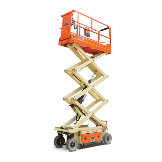
JLG 1930ES Service Maintenance Manual
Electric scissor lift
Hide thumbs
Also See for 1930ES:
- Service maintenance manual (212 pages) ,
- Operation and safety manual (136 pages) ,
- Operation & safety manual (50 pages)
Chapters
Table of Contents
Troubleshooting

Related Manuals for JLG 1930ES


Summary of Contents for JLG 1930ES
- Page 1 Service & Maintenance Manual Models 1930ES 2032ES 2632ES 2646ES 3246ES USA Built - S/N-0200239382 to Present China Built - S/N-B200020297 to Present Mexico Built - S/N-M200000100 to Present 3121656 March 7, 2016...
-
Page 3: Section A. Introduction - Maintenance Safety Precautions
Relieve system pressure by cycling the applicable con- trol several times with the engine stopped and ignition on, to direct any line pressure back into the reservoir. Pressure feed lines to system components can then be disconnected with minimal fluid loss. 3121656 – JLG Lift –... - Page 4 INTRODUCTION - MAINTENANCE SAFETY PRECAUTIONS REVISION LOG Original Issue - December 11, 2014 Manual Revised - July 28, 2015 Manual Revised - March 7, 2016 – JLG Lift – 3121656...
-
Page 5: Table Of Contents
Lubrication and Information ............. . 2-4 3121656 – JLG Lift –... - Page 6 1930ES Only ........
- Page 7 Motor Removal ..............4-15 SECTION 5 - JLG CONTROL SYSTEM Diagnostic Port.
- Page 8 Hydraulic Schematic..............7-24 – JLG Lift –...
- Page 9 Pothole Switch Adjustment - 1930ES/2032ES/2632ES........
- Page 10 Hydraulic Schematic - China Manufactured..........7-26 – JLG Lift –...
- Page 11 Machine Configuration Programming Information ........5-26 3121656 – JLG Lift –...
- Page 12 TABLE OF CONTENTS NOTES: viii – JLG Lift – 3121656...
-
Page 13: Section 1. Specifications
2091 kg (Dual) Ground Clearance with pot hole 3.5 in (8.9 cm) 5 in. (12.7 cm) protection system up Ground Clearance with pot hole 1 in (2.5 cm) 0.75 in (1.9 cm) protection system down 3121656 – JLG Lift –... -
Page 14: Capacities
1930ES 2032ES 2632ES 2646ES 3246ES Hydraulic Tank 2 Gal 2 Gal 3 Gal (7.6 L) (7.6 L) (11.3 L) Hydraulic System (Including Tank) 2.2 Gal 2.8 Gal 5.3 Gal (8.3 L) (10.6 L) (19.9 L) – JLG Lift – 3121656... -
Page 15: Tires
PROPER BATTERY REPLACEMENT, PLEASE CONTACT YOUR LOCAL JLG SUPPORT OFFICE. Maximum Interlock Current — INPUT BATTERIES APPROVED BY JLG HAVE BEEN TESTED FOR COMPAT- AC Input Voltage 85-265VAC 108-132VAC IBILITY WITH THE ALGORITHM PROGRAMMING OF THE DELTA Nominal AC Input Voltage... -
Page 16: Travel Speed
6 - 7.9 2632ES 28-37 33 - 38 6 - 7.9 6 - 7.9 2646ES 28-37 33 - 38 6.4 - 8.3 6.4 - 8.3 3246ES 28-37 33 - 38 6.4 - 8.3 6.4 - 8.3 – JLG Lift – 3121656... -
Page 17: Model Dimensions
4.2 ft (0.9 m) 0.9 m) (0.9 m) (1.3 m) (1.3 m) Wheelbase 63 in 74 in 74 in 82.30 in 82.30 in (160 c m) (188 c m) (188 c m) (209 cm) (209 cm) 3121656 – JLG Lift –... -
Page 18: Torque Requirements
105 -120 ft lb comparable viscosities. If use of hydraulic oil other (142-163 Nm) than DTE 11M is desired, contact JLG Industries for proper recommendations. NOTE: Anytime a wheel bolt is replaced, be sure one of the same length is used. Use bolt shown below on wheels that use the 1/4"... -
Page 19: Pressure Settings
76 in (1.9 m) for country of origin. USA built machines, serial num- ber prefix starts with a 02 (02XXXXXXXX), China built 3246ES 76 in (1.9 m) machines, serial number prefix starts with an B2 (B2XXXXXXXX). 3121656 – JLG Lift –... -
Page 20: Cylinder Specifications
283 lbs (128 kg) Batteries: (each) 220 Amp 60 lbs (27 kg) 60 lbs (27 kg) 220 Amp (used with Inverter/Charger) 66 lbs (30 kg) 66 lbs (30 kg) 245 Amp 70 lbs (32 kg) – JLG Lift – 3121656... -
Page 21: Torque Charts
SECTION 1 - SPECIFICATIONS TORQUE CHARTS Figure 1-1. Torque Chart - Sheet 1 of 5 - (SAE Fasteners) 3121656 – JLG Lift –... -
Page 22: Torque Chart - Sheet 2 Of 5 - (Sae Fasteners)
SECTION 1 - SPECIFICATIONS Figure 1-2. Torque Chart - Sheet 2 of 5 - (SAE Fasteners) 1-10 – JLG Lift – 3121656... -
Page 23: Torque Chart - Sheet 3 Of 5 - (Sae Fasteners)
SECTION 1 - SPECIFICATIONS Figure 1-3. Torque Chart - Sheet 3 of 5 - (SAE Fasteners) 3121656 – JLG Lift – 1-11... -
Page 24: Torque Chart - Sheet 4 Of 5 - (Metric Fasteners)
SECTION 1 - SPECIFICATIONS Figure 1-4. Torque Chart - Sheet 4 of 5 - (METRIC Fasteners) 1-12 – JLG Lift – 3121656... -
Page 25: Torque Chart - Sheet 5 Of 5 - (Metric Fasteners)
SECTION 1 - SPECIFICATIONS Figure 1-5. Torque Chart - Sheet 5 of 5 - (METRIC Fasteners) 3121656 – JLG Lift – 1-13... - Page 26 SECTION 1 - SPECIFICATIONS NOTES: 1-14 – JLG Lift – 3121656...
-
Page 27: Section 2 - General
Technician as a person who has successfully completed gram. The following table outlines the periodic machine the JLG Service Training School for the subject JLG prod- inspections and maintenance recommended by JLG uct model. Reference the machine Service and Mainte- Industries, Inc. -
Page 28: Service And Guidelines
Service and Maintenance Man- Pre-Delivery Prior to each sale, lease, or Owner, Dealer, or User Qualified JLG Mechanic ual and applicable JLG inspec- Inspection rental delivery. tion form. In service for 3 months or 150 hours, whichever comes first; or... -
Page 29: Component Disassembly And Reassembly
If a bolt is too short, there will not be enough thread area to engage and hold the part properly. When replacing bolts, use only those 3121656 – JLG Lift –... -
Page 30: Lubrication And Information
Chart. 1. Refer to Section 1 for recommendations for viscos- ity ranges. 2. JLG recommends DTE11 hydraulic oil, which has an SAE viscosity of 10W-30 and a viscosity index of 152. NOTE: Start-up of hydraulic system with oil temperatures below -15°F (-26°C) is not recommended. -
Page 31: Cylinder Drift Test
NOTE: This information is based on 6 drops per minute cyl- c. Pins should be inspected to ensure it is free of inder leakage. burrs, nicks, and scratches which would dam- age the bearing during installation and opera- tion. 3121656 – JLG Lift –... -
Page 32: Preventive Maintenance And Inspection Schedule
MACHINE INSPECTION REPORT" FORM. for straightness of rod. NOTE: This machine requires periodic safety and mainte- 14. Check for condition of element; replace as neces- nance inspections by a JLG Dealer. Notify dealer if sary. inspection is overdue. 15. Check for proper inflation. -
Page 33: Preventive Maintenance And Safety Inspection
Wheel and Tire Assemblies Drive Motors 1,5,6 Drive Brakes Drive Torque Hubs 1,3,5,6 Steer Cylinder 5,6,13 Steer Components Wheel Bearings Scissor Arms Safety Props Sliding Wear Pads 8,12 Pivot Pins/Bolts Switches, Ground Control 1,11 Control Tags 3121656 – JLG Lift –... - Page 34 SECTION 2 - GENERAL NOTES: – JLG Lift – 3121656...
-
Page 35: Section 3 - Chassis & Scissor Arms
On level terrain, the Power Line Contactor Right Field Winding Armature Right Left MOSFET Armature Armature Field Shunt Left Field Winding MOSFETS Power Module Figure 3-1. Traction Control Circuit - ZAPI Power Module 3121656 – JLG Lift –... -
Page 36: Drive Motor Electrical Evaluation
(plat- cables during this analysis. form stowed). Under DIAGNOSTICS - TRACTION, the JLG Analyzer's ARM CUR display (Armature Current Reading) will exceed 120A. The FLD CUR • Resistance < 2 Ohms Red to Black Armature Wires. -
Page 37: Power Module Electrical Evaluation
Armature portion of form stowed). Under DIAGNOSTICS - TRACTION, Traction. Place the Red meter lead on +B, and the the JLG Analyzer's ARM CUR display (Armature Black meter lead on M1. Current Reading) will exceed 120A. The FLD CUR •... -
Page 38: Torque Hub
However, if the unit is under warranty you should unit, then checking for air bubbles. If a leak is detected contact JLG Industries, Inc. for a replacement unit. in a seal, o-ring or gasket, the part must be replaced, The warranty will no longer be valid if the unit is dis- and the unit rechecked. -
Page 39: Brakes - Manual Disengage Procedure
6. Repeat this procedure on opposite wheel drive. With both drive motor brakes now disengaged, the machine can be moved manually. 7. After towing is complete, chock wheels and remove Cover Bolts from Disengage Holes. 8. Reinstall Brake Cover. 3121656 – JLG Lift –... -
Page 40: Drive Motor Removal
POSITION BEFORE REMOVING DRIVE MOTOR. 1. Disconnect the motor cable from the power con- trol module. 2. Drain the oil out of the unit by removing the cover plug. Note the condition of the oil, replace if nec- essary. – JLG Lift – 3121656... -
Page 41: Main Gearbox Disassembly
6. Remove input ring gear. NOTE: The input ring gear is held in with a press fit on its outside diameter. Insert jacking screws (1/4-20UNC grade 8) with at least 1.5 inches of thread length into 3121656 – JLG Lift –... -
Page 42: Input Carrier Disassembly
6. Remove the thrust washer from each planet gear. 7. Remove retaining ring from output sun gear. 8. Slide output sun gear out from the center of the input carrier. 9. Remove the three planet shafts from the input car- rier. – JLG Lift – 3121656... -
Page 43: Hub Disassembly
The lip seal will most likely become dam- of the bearing. Apply force to the push the bearing aged during removal. Try not to damage the hub out. This bearing will need to be replaced upon reas- bore. sembly. 3121656 – JLG Lift –... -
Page 44: Spindle Disassembly
4. Using a screwdriver remove the shaft bearing snap ring. 5. Remove the shaft ball bearing from the center bore. 3-10 – JLG Lift – 3121656... -
Page 45: Spindle Sub-Assembly
16. Grease and install the motor O’ring into the groove. CARE SHOULD BE TAKEN TO PREVENT ANY OIL FROM MAKING CONTACT WITH THE BRAKE DISCS. IF THIS OCCURS IT WILL DEGRADE THE BRAKES PERFORMANCE. 3121656 – JLG Lift – 3-11... -
Page 46: Hub Sub-Assembly
NOTE: The seal has a thin outer shell that can be easily dam- aged if not installed with care. It is a good idea to start the seal into the bore with a rubber mallet before pressing. 3-12 – JLG Lift – 3121656... -
Page 47: Input Carrier Sub-Assembly
NOTE: Do not overstress the snap ring. 5. Place a thrust washer on each side of the input planet gear. Line up the bores as well as you can 3121656 – JLG Lift – 3-13... -
Page 48: Main Gearbox Assembly
You will need to pull the teeth of the hub hit the gear teeth of the 3 out- retaining ring apart and work it into the groove. put planets. 3-14 – JLG Lift – 3121656... - Page 49 The grease will help keep it in the bore during assembly. NOTE: Do not use excessive pressing force because it will be 11. Center the cover in the hub bore so that the “JLG” reacted by the main wheel bearings. logo is up. Push it into the bore.
-
Page 50: Motor And Brake Assembly
NOTE: The motor may need to be rotated to line up the sun gear splines with the motor shaft splines. 2. Install the two motor mounting bolts and washers. Torque to 9 - 11 ft-lbs (12 - 15 Nm). 3-16 – JLG Lift – 3121656... -
Page 51: Tightening And Torquing Bolts
BO L T A Figure 3-13. Assembly Tool 2 B O L T B Assembly Tools Figure 3-14. Assembly Tool 3 Figure 3-12. Assembly Tool 1 3121656 – JLG Lift – 3-17... -
Page 52: Drive Motor Cable Routing
1. Cable Clamp 3. Capscrew, Washers, and 2. Cable Clamp 2. Spacer Plate 3. Spacer Plate 8. Reconnect battery cable plug. Power up machine and operate the drive function to ensure drive motors operate properly. 3-18 – JLG Lift – 3121656... -
Page 53: 2032Es/2632Es/2646Es/3246Es Only
3. Bolt the Green Clamp onto the backside of the frame using the the back hole drilled in step #4. The roll pins inserted in the front-most holes act as a stop to prevent the clamp from turning. 3121656 – JLG Lift – 3-19... -
Page 54: Electric Drive Motor Service
15. Brake Cover Mounting Screws 4. Brush Spring 10. Grommet 16. Terminal Cover Mounting Screws 5. Brush & Terminal Assembly 11. Brake Assembly 6. Brush Box Assembly 12. Gasket Seal Kit Figure 3-15. Drive Motor Components 3-20 – JLG Lift – 3121656... -
Page 55: Servicing Guidelines
4. Using a dielectric tester, verify that there are no 1. Carefully blow out any accumulated carbon dust shorts between the following items: and dirt from the Commutator End Head (9) and a. Field connector pins and the case of the motor. 3121656 – JLG Lift – 3-21... -
Page 56: Drive Motor Reassembly
Align wires because bearings may have been damaged during from the Brake Assembly (11) into the notch in the removal. Although the bearings may appear and 3-22 – JLG Lift – 3121656... -
Page 57: Wire Harness Connections
Torque top nut to 90 - 110 in-lb (10.2 - 12.4 Nm). Figure 3-17. Wire Harness Connections 3121656 – JLG Lift – 3-23... -
Page 58: Power Module - Zapi
Figure 3-18., made, the batteries can be reconnected. ZAPI Power Module Location. Use the following instruc- 9. Reinstall the power module cover, then check for tions when replacing the power module. normal machine operation. 3-24 – JLG Lift – 3121656... -
Page 59: Zapi Power Module Electrical Evaluation
The LED blinks (2Hz) when an internal issue is detected that cannot be repaired by a technician. It should be noted that this will trigger replacement of the device. P/N - 1001092456 ZAPI Power Module - "HEALTH" (Status LED) 3121656 – JLG Lift – 3-25... -
Page 60: Mdi (Multifunction Digital Indicator) And Brake Release
3.6 ft-lb (5 Nm). (Refer to Figure 3-19.) Plugs (2). 1. Diagnostic Port 2. Brake Release Plugs 3. Apply di-electric grease to the two Brake Release Plugs. Connect the Brake Release Plugs to the 3-26 – JLG Lift – 3121656... -
Page 61: Mdi Installation/Removal
"Error" will display on the LCD. If a fault exists, the trouble code will display on the LCD. (Refer to Sec- tion 6, Diagnostic Trouble Codes) 6. Using zip ties, tie back cables and wires to prevent damage to the cables and wires. Removal: 3121656 – JLG Lift – 3-27... -
Page 62: Battery Removal
8. Reconnect batteries and check for proper opera- LOCAL JLG SUPPORT OFFICE. tion. BATTERIES APPROVED BY JLG HAVE BEEN TESTED FOR COMPAT- IBILITY WITH THE ALGORITHM PROGRAMMING OF THE DELTA Q BATTERY CHARGER TO OPTIMIZE BATTERY LIFE AND MACHINE CYCLE TIMES. THE USE OF NON APPROVED BATTERIES IN YOUR JLG EQUIPMENT MAY RESULT IN PERFORMANCE ISSUES OR BATTERY CHARGER FAULT CODES. -
Page 63: Battery Maintenance And Safety Practices
VENT TUBE 1/8 " PLATES Figure 3-20. Battery Fluid Level 1. AC Voltage - Input Cable 3. DC Power Cable to Batteries 2. Charger Interlock Cable 4. LED Indicator Cable Figure 3-22. Battery Charger 3121656 – JLG Lift – 3-29... -
Page 64: Battery Charger Maintenance
Confirm that a nominal battery voltage is the same as the char- ger voltage. 3. This fault will clear automatically when the low battery voltage problem is rectified. 3-30 – JLG Lift – 3121656... - Page 65 1. Confirm that the battery pack is not too small - This fault indicates the charger has become too hot dur- usually > 50Ah. ing operation. Though not damaging to the charger, charge time will be extended significantly. 3121656 – JLG Lift – 3-31...
-
Page 66: Battery Algorithms
Trojan T105 4. If the output voltage of the charger seems exces- East Penn GC-110-WNL sive, return the charger for service. Contact JLG to Trojan T105 PLUS get the expected battery voltage settings for the Champion CHGC2 GC2 charger in question. -
Page 67: Battery Charger/Inverter (Option)
Use the information below to supplement the informa- tion in the Inverter/Charger manual. First, go through the troubleshooting in the Owner’s Guide (JLG part number 3128406), then use the procedures below. For control of the Inverter/Charger there is an 8 position connector on a cable entering the case of the Inverter/ Charger. - Page 68 4. Turn off machine. 5. Disconnect Inverter/Charger control cable at the charger. 6. Inverter/Charger connector (8 position) pin 6 should have continuity to Interlock connector pin 2 and then to ground module socket J1-29. 3-34 – JLG Lift – 3121656...
-
Page 69: Limit Switch Locations
SECTION 3 - CHASSIS & SCISSOR ARMS 3.11 LIMIT SWITCH LOCATIONS 5. Pothole Switch (Typical on opposite side of machine) 6. Rotary Angle Switch Figure 3-25. Limit Switch Locations 3121656 – JLG Lift – 3-35... -
Page 70: Pothole Switch Replacement
NOTE: From the platform, raise and lower the machine and check that the switch is operating properly by cutting back to elevated speed when the pothole is deployed. Drive will be cutout if pothole is not set. 3-36 – JLG Lift – 3121656... -
Page 71: Ground Control Station
SECTION 3 - CHASSIS & SCISSOR ARMS 3.12 GROUND CONTROL STATION NOTE: Anytime the ground control box is removed, the tilt sensor must be re-calibrated. Refer to Section 5, JLG Control System to re calibrate the tilt. Box Disassembly 5. Remove the six bolts at the back of the ground control and separate. -
Page 72: Tilt Sensor Replacement
SECTION 3 - CHASSIS & SCISSOR ARMS Tilt Sensor Replacement 1. Ground Control Station 2. Tilt Sensor (JLG P/N 4000021 or 1001114936) Figure 3-45. Tilt Sensor Location Tilt Sensor Removal: 1. Disconnect the batteries. 1. Tilt Sensor 2. Open the Ground Control Station to gain access to 2. -
Page 73: Scissor Arms And Platform Positioning And Support
FOR MACHINES EQUIPPED WITH LOAD SENSING SYSTEM (LSS), deforming locknuts, are not intended to be reinstalled after removal. Always use new replacement hardware ENSURE ARROWS ON THE LSS PIN ARE POINTING DOWN when installing locking fasteners. 3121656 – JLG Lift – 3-39... -
Page 74: Arms And Platform Positioning And Support
SECTION 3 - CHASSIS & SCISSOR ARMS Figure 3-47. Arms and Platform Positioning and Support 3-40 – JLG Lift – 3121656... -
Page 75: Platform Control Station
NOTE: You may have to only loosen the two power bolts and remove the two closest the top in order to get to the printed circuit board located in the top of the control box where the drive/lift select switch is located. 3121656 – JLG Lift – 3-41... -
Page 76: Joystick Controller
VIOLET TRIGGER N.O. Output: Full Positive (Reverse) Deflection 4 (±0.1) VDC SPARE Output: Full Negative (Forward) Deflection 1 (±0.1) VDC YELLOW ROCKER RT GREEN ROCKER LT SPARE WHITE/RED +5VDC WHITE/BLACK GROUND BROWN SIG OUTPUT 3-42 – JLG Lift – 3121656... -
Page 77: Section 4 - Hydraulics
The relief valve provides an alternate path for the continuing flow from the pump, 3121656 – JLG Lift –... -
Page 78: Pump/Motor - Theory Of Operation
(Lift Up from Ground Mode). or burned winding. Common Difficulties The following difficulties can be examined using the JLG Analyzer, a voltmeter, and simple hand tools. Unless other- wise noted, the Control System shall be energized in Ground Mode during testing. - Page 79 Steer Functionality will be lost and the Pump ated from Ground Mode. Motor will not operate. Under DIAGNOSTICS - PUMP, the JLG Analyzer will show an erratic read- As shown in the diagram, the voltage measured ing for PUMP PWM % and PUMP CUR will hover...
-
Page 80: Cylinder Checking Procedure
5. Remove plug from P port (3) and install a pressure gauge. 6. Raise the platform and take a pressure reading. 7. Adjust the Pressure Setting Screw to reach the proper lift pressure per model as listed in Table 4- – JLG Lift – 3121656... -
Page 81: Hydraulic Oil Fill
(134 bar ± 3.4 bar) (131 bar ± 3.4 bar) (103 bar) NOTE: The 2632ES/2646ES/ 3246ES platforms will have to be raised higher than the 1930ES and 2032ES in 2000 psi +/- 50 psi 1900 psi ± 50 psi 1500 psi 2646ES order to access the oil plug. -
Page 82: Slide Block Lubrication
7. Remove the 4 bolts that attach the pump/motor assembly to the lift cylinder. 8. Remove the bolt from the bracket that attaches the hydraulic reservoir to the lift cylinder. 9. Separate the cylinder from the pump/motor assembly. Upper Slide Pad Channel – JLG Lift – 3121656... -
Page 83: Lift Cylinder Removal
SECTION 4 - HYDRAULICS 1. Battery Cables 3. Manual Descent 5. Top Cylinder Bolt (Torque 41 ft. lb.) 2. Valves 4. Steer Hoses 6. Bottom Cylinder Bolt Figure 4-2. LIft Cylinder Removal 3121656 – JLG Lift –... -
Page 84: Cylinder Repair
13. Remove the bushing from the piston. 6. Using a spanner wrench, loosen the spanner nut retainer, and remove spanner nut from cylinder 14. Screw the piston CCW, by hand, and remove the barrel. piston from cylinder rod. – JLG Lift – 3121656... -
Page 85: Steer Cylinder Piston Removal
Dress threads as necessary. sary. 8. Inspect seal and o-ring grooves in piston for burrs 17. If applicable, inspect piston rings for cracks or and sharp edges. Dress applicable surfaces as nec- essary. other damage. Replace as necessary. 3121656 – JLG Lift –... -
Page 86: Assembly
SECTION 4 - HYDRAULICS Assembly NOTE: Prior to cylinder assembly, ensure that the proper cyl- inder seal kit is used. See your JLG Parts Manual (3121167). Apply a light film of hydraulic oil to all components prior to assembly. 1. A special tool is used to install a new rod seal into the applicable cylinder head gland groove. -
Page 87: Piston Seal Kit Installation
Figure 4-11. Rod Assembly Installation 4. Assemble the tapered bushing loosely into the pis- ton and insert JLG capscrews (not vendor cap- 14. After the cylinder has been reassembled, the rod screws) through the drilled holes in the bushing should be pushed all the way in (fully retracted) and into the tapped holes in the piston. -
Page 88: Holding Valve Torque Specifications
23. If applicable, install the cartridge-type holding valve and fittings in the port block using new o- rings as applicable. Refer to Table 4-3, Holding Valve Torque Specifications. 4-12 – JLG Lift – 3121656... -
Page 89: Pump Removal
10. Replace the o-ring if necessary. c. Place tank on a suitable work bench or work area. NOTE: The filter and bypass are located on the pickup tube inside the tank. The filter should be changed once a year. 3121656 – JLG Lift – 4-13... - Page 90 NOTE: There are two orings used to seal the pump to the valve body, one for the pump inlet (shown above) and one on the pump boss around the drive coupler. 4-14 – JLG Lift – 3121656...
-
Page 91: Motor Removal
1. Remove the four bolts attaching the motor to the remove fill plug and refill tank with proper grade valve body. of oil by using a funnel. Fill until oil weeps out of opening. 4. Replace plug and torque to 40 ft. lbs. 3121656 – JLG Lift – 4-15... -
Page 92: Lift Cylinder/Pump/Tank Assembly
Proportional Valve 15 ft lbs (20 Nm) Check Valve 33 ft lbs (45 Nm) Blocking Valve 15 ft lbs (20 Nm) 4 Way Directional Valve 15 ft lbs (20 Nm) Extend Port Retract Port 4-16 – JLG Lift – 3121656... -
Page 93: Lift Cylinder Assembly
22. O-ring 28. Coil 4. Relief Valve 5. Pump 11. Wear Ring 17. Head 23. Bushing 29. Directional Control Valve 6. Filter 12. Seal 18. O-ring 24. Cylinder Rod Figure 4-13. Lift Cylinder Assembly 3121656 – JLG Lift – 4-17... - Page 94 SECTION 4 - HYDRAULICS NOTES: 4-18 – JLG Lift – 3121656...
-
Page 95: Section 5 - Jlg Control System
To Connect the Hand Held Analyzer: at the near the ground control station as shown below. The MDI (Multifunction Digital Indicator) and the JLG 1. Connect the four pin end of the cable supplied Hand-Held Analyzer can be connected at this port.. -
Page 96: Using The Analyzer
SECTION 5 - JLG CONTROL SYSTEM Using the Analyzer: If ENTER is pressed again, the display moves to the fol- With the machine power on and the analyzer connected lowing display: properly, the analyzer will display the following: l og:... -
Page 97: Changing The Access Level Of The Hand Held Analyzer
SECTION 5 - JLG CONTROL SYSTEM Changing the Access Level of the Hand Held Analyzer: When the analyzer is first connected, you will be in access level 2 which enables you to only view most con- M ENU: figuration settings which cannot be changed until you AC C ESS LEVEL 1 enter a password to advance to a lower level. -
Page 98: Adjusting Parameters Using The Hand Held Analyzer
SECTION 5 - JLG CONTROL SYSTEM Adjusting Parameters Using the Hand Held Machine Setup Analyzer When a machine digit item is selected, press the UP or DOWN arrow keys to adjust its value, for example: Once you have gained access to level 1, and a personal-... -
Page 99: Tilt Sensor Calibration
SECTION 5 - JLG CONTROL SYSTEM TILT SENSOR CALIBRATION Be sure that the machine is parked and stowed on level CHANGING THESE SETTINGS MAY ADVERSELY AFFECT THE PER- ground. FORMANCE OF YOUR MACHINE. NOTE: Tilt Sensor Calibration can not be performed if the main contactor switch is open due to an alarm. -
Page 100: Tilt Sensor Electrical Evaluation
For the following troubleshooting steps, a bubble level TILT SENSOR ELECTRICAL EVALUATION (smaller is better) will be needed and the machine must This basic check using the JLG Analyzer can be used to be on a level surface: test the Tilt Sensor. -
Page 101: Tilt Vs. Allowed Height Evaluation
Therefore, replace the sensor and return to JLG with a machine and re calibrate the Elevation Sensor. detailed troubleshooting description. -
Page 102: Elevation Sensor Calibration
NOTICE computer, connecting cable, and software update cd. MACHINE MUST BE ON LEVEL GROUND BEFORE ELEVATION SEN- Contact JLG Industries to acquire the software cd. SOR CAN BE SET. Before updating the software, use the Hand-held Ana- lyzer to view the machine’s settings (MACHINE SETUP 1. -
Page 103: Troubleshooting
SECTION 5 - JLG CONTROL SYSTEM TROUBLESHOOTING It should be noted that there is no substitute for a thorough knowledge of the equipment and related systems. It should be recognized that the majority of the problems arising in the machine will be centered in the hydraulic and electrical systems. - Page 104 SECTION 5 - JLG CONTROL SYSTEM Table 5-2. Flash Code Listing Flash Help Message Cause Possible Resolve Code While stowed, drive speed is reduced (due to lower ground clearance) since the control system detected that the pot-hole Clear the obstacle blocking the protection mechanism is deployed (failed to retraced).
- Page 105 SECTION 5 - JLG CONTROL SYSTEM Table 5-2. Flash Code Listing Flash Help Message Cause Possible Resolve Code The Drive - Lift selector switch indicates that both functions are selected simultaneously. In Platform Mode, the Drive and Lift Digital Inputs are Ener- Repair the wiring or switch to FUNCTION PROBLEM -- DRIVE &...
- Page 106 SECTION 5 - JLG CONTROL SYSTEM Table 5-2. Flash Code Listing Flash Help Message Cause Possible Resolve Code Help messages with the 2-3 flash code indicate difficulty with the ground controls. Lift switch (up or down) in the ground control box was closed during power-up.
- Page 107 SECTION 5 - JLG CONTROL SYSTEM Table 5-2. Flash Code Listing Flash Help Message Cause Possible Resolve Code The Elevation Sensor’s Calibration EEPROM is set to the signa- ture implanted by the In-Circuit Test Fixture. Retained until Calibration EEPROM is over-written by a valid calibration.
- Page 108 SECTION 5 - JLG CONTROL SYSTEM Table 5-2. Flash Code Listing Flash Help Message Cause Possible Resolve Code The Elevation Proximity Switch is closed to indicate that the platform is stowed, but the elevation sensor’s voltage indicates that the platform is elevated. To be conservative, the control ELEV PROX PERMANENTLY CLOSED –...
- Page 109 SECTION 5 - JLG CONTROL SYSTEM Table 5-2. Flash Code Listing Flash Help Message Cause Possible Resolve Code The Power Module’s Line Contactor Drive Circuitry failed to de- energize during power-up self-tests. Refer to CANbus documentation The Power Module is reporting a “Contactor Driver 1 Perma-...
- Page 110 SECTION 5 - JLG CONTROL SYSTEM Table 5-2. Flash Code Listing Flash Help Message Cause Possible Resolve Code Current flow to the steer left solenoid was not detected during power-up. STEER LEFT OPEN CIRCUIT Left Turn INPUT driven High (momentarily) AND Left Turn STAT detected Low during power-up.
- Page 111 SECTION 5 - JLG CONTROL SYSTEM Table 5-2. Flash Code Listing Flash Help Message Cause Possible Resolve Code Check for continuity through The ground board did not detect current flow to the right brake this circuit. Inspect the wiring RIGHT BRAKE OPEN CIRCUIT during normal operation.
- Page 112 1000mS. Retained until power is re-cycled. No motion interlocks. Help messages with the 6-7 flash code indicate JLG accessory problems. These faults shall not be latched. Normal operation shall resume if difficulty is resolved. A JLG Accessory Module has encountered a fault condition and reported it via the host control system.
- Page 113 SECTION 5 - JLG CONTROL SYSTEM Table 5-2. Flash Code Listing Flash Help Message Cause Possible Resolve Code Cell #2’s Bridge <2Vdc, >3Vdc, or could the LSS Module could not read Cell #2’s Internal Memory. This situation indicates that the...
- Page 114 SECTION 5 - JLG CONTROL SYSTEM Table 5-2. Flash Code Listing Flash Help Message Cause Possible Resolve Code The Excitation Voltage for the Load Sensors < 4.25V. 9-9 Flash Code The sensors may be excessively LSS Module Message – Status Message (0x81) is reporting loading the Excitation Supply LSS INTERNAL ERROR –...
- Page 115 Cause Possible Resolve Code The control system has not been configured for the first time. Use the JLG Analyzer to adjust all 9-9 Flash Code FUNCTIONS LOCKED OUT – MACHINE NOT CONFIGURED Machine Setup and Personality The control system’s EEPROM flag indicates that the vehicle has settings and re-cycle power to not been configured (new control system components).
- Page 116 SECTION 5 - JLG CONTROL SYSTEM Analyzer Flow Chart 5-22 – JLG Lift– 3121656...
- Page 117 SECTION 5 - JLG CONTROL SYSTEM 3121656 – JLG Lift – 5-23...
- Page 118 SECTION 5 - JLG CONTROL SYSTEM 5-24 – JLG Lift– 3121656...
-
Page 119: Machine Model Adjustment
SECTION 5 - JLG CONTROL SYSTEM MACHINE MODEL ADJUSTMENT Table 5-3. Machine Model Adjustment Adjustment Adjustment Range 1930ES 2032ES 2632ES 2646ES 3246ES DRIVE ACCEL 0.1 - 5.0 (Sec) DECEL 0.1 - 1.0 (Sec) MINIMUM 0 - 25% MAXIMUM 0 -100% ELEV. -
Page 120: Machine Configuration Programming Information
SECTION 5 - JLG CONTROL SYSTEM 5.10 MACHINE CONFIGURATION PROGRAMMING INFORMATION NOTE: When configuring an ES scissors machine, the machine configuration must be completed before any personality set- tings can be changed. Changing the personality settings first and then changing the model number of the machine con- figuration will cause the personality settings to return to default. -
Page 121: Section 6 - Diagnostic Trouble Codes
257 ELEV PROX PERMANENTLY CLOSED - CHECK PROX AND ANGLE ADJUSTMENT ............... 6-9 258 DRIVE & LIFT PREVENTED - BRAKES ELECTRICALLY RELEASED FOR TOWING ..............6-10 259 MODEL CHANGED - HYDRAULICS SUSPENDED - CYCLE EMS ....................6-10 3121166 – JLG Lift –... - Page 122 6635 CANBUS FAILURE - CHASSIS TILT SENSOR ............................6-17 671 ACCESSORY FAULT ....................................6-17 771 OPEN CIRCUIT DRIVE MOTOR WIRING .............................6-17 772 STALLED TRACTION MOTOR OR POWER WIRING ERROR......................6-17 773 CAPACITOR BANK FAULT - CHECK POWER CIRCUITS .........................6-18 – JLG Lift – 3121166...
- Page 123 99146 POWER MODULE FAILURE - INTERNAL ERROR ........................6-23 99147 POWER MODULE FAILURE - INTERNAL ERROR ........................6-23 99148 POWER MODULE FAILURE - INTERNAL ERROR ........................6-23 99149 POWER MODULE FAILURE - INTERNAL ERROR ........................6-23 3121166 – JLG Lift –...
-
Page 124: Dtc Check Tables
• Backprobing ground board J1-10 should show about 0 volts. • Check function of elevation angle sensor. ANALYZER - > DIAGNOSTICS -> ELEV SENSOR -> ZEROED should be about 0V when stowed and about 0.15V at cut- back. – JLG Lift – 3121166... -
Page 125: Drive & Lift Up Prevented - Tilted & Elevated
After 2 hours without activity, • Normal operation should resume after a power cycle. OUT - SYSTEM POW- the control system enters a low- • Check batteries charge, condition, etc. ERED DOWN power state to preserve battery charge. 3121166 – JLG Lift –... -
Page 126: Power-Up
Its input (0V) is from platform board ter- minal J1-11. "Lift" selection output (0V when selected) is to platform board terminal J1-9. "Drive" selection output (0V when closed) is to platform board terminal J1-10. • Replace platform board. – JLG Lift – 3121166... -
Page 127: Function Problem - Steer Left Permanently Selected
• Check the trigger switch signal and wiring to the plat- TRAL the joystick was centered. form board. The trigger input (24V) is from platform board terminal J1-1, and its output (24V when closed) is to platform board terminal J1-8. • Replace platform board. 3121166 – JLG Lift –... -
Page 128: Ground Controls
The elevation angle sensor input is from ground board terminal J1-14 (4.7V), its output (0.1 - 1.2V when stowed) is to ground board terminal J1-15, and its ground is to ground board terminal J1- • Replace the ground board. – JLG Lift – 3121166... -
Page 129: Elev Angle Sensor Has Not Been Calibrated
The switch should close imity switch is only found on cer- when placed in close proximity to ferrous metal. tain older lifts. This switch is not used on current machines so this DTC should not occur. 3121166 – JLG Lift –... -
Page 130: Line Contactor Open Circuit
Drive, • Contactor solenoid resistance should measure about steer and lift up prevented. 52 Ohms. • Check continuity between contactor connector pin 2 and power module connector socket 8. • Replace power module. 6-10 – JLG Lift – 3121166... -
Page 131: Line Contactor Short Circuit
The lift up solenoid is powered with 24V from ground board J1-25, and its ground is to ground board J1-30, • Inspect the wiring for physical damage. • Replace ground board. 3121166 – JLG Lift – 6-11... -
Page 132: Lift Dn Short To Battery
28, and its ground is to ground board J1-30, 37. There should be about 1500 Ohms between ground alarm connector pin 1 and pin 3. • Inspect the wiring for physical damage. • Replace ground board. 6-12 – JLG Lift – 3121166... -
Page 133: 3312 Left Brake Short To Battery
• ZAPI - HEALTH (Status LED) - ON 33304 RIGHT BRAKE - SHORT Drive, and Steer Prevented • Excessive current flow to the Right Brake solenoid was TO GROUND detected (J1-33 NRB). • ZAPI - HEALTH (Status LED) - ON 3121166 – JLG Lift – 6-13... -
Page 134: Thermal Limit (Soa)
• Check for excessively high current consumption in the pump, ANALYZER -> DIAGNOSTICS -> PUMP -> PUMP CUR over 130 Amps with an empty deck. • Refer to Pump Motor Electrical Evaluation in Section 4.8. 6-14 – JLG Lift – 3121166... -
Page 135: Battery Supply
10 should have continuity. Ground board socket J1-32 to power module connector socket 11 should have continuity. • Turn on machine in platform mode. If DTC 662 is pres- ent, troubleshoot that DTC before continuing. 3121166 – JLG Lift – 6-15... -
Page 136: Communication
Disconnect power module connector. Turn on in platform mode. If DTC 662 is no longer present replace power module. • If DTC 661 and 662 have been present through above steps replace ground board. Continued Next Page 6-16 – JLG Lift – 3121166... -
Page 137: Accessory
> 4.5V or < 0.5V. This is mostly likely caused by a ING ERROR stalled traction motor or power wiring issue. Alter- nately, it could be an internal fault. • ZAPI - HEALTH (Status LED) - ON 3121166 – JLG Lift – 6-17... -
Page 138: Capacitor Bank Fault - Check Power Circuits
• VMN does not increase more than 1.3V • VMN is less than 20% Battery Voltage • Battery Voltage . VMN is greater than 4V • ZAPI - HEALTH (Status LED) - ON 6-18 – JLG Lift – 3121166... -
Page 139: Tilt Sensor
3124288. 823 LSS CELL #3 ERROR A problem has been detected • Refer to Section 2.3: Troubleshooting in the LSS man- with the load sense system. ual, 3124288. 3121166 – JLG Lift – 6-19... -
Page 140: Hardware
IMPROPER 9910 FUNCTION LOCKED The platform board software • Reprogram platform board. OUT - PLATFORM MOD- version is not compatible with ULE SOFTWARE VER- the rest of the system. SION IMPROPER 6-20 – JLG Lift – 3121166... -
Page 141: 9912 Power Module Failure - System Monitor
• Software issue on the controller. Update software. LOST manded. 9924 FUNCTIONS LOCKED The control system's memory • Use the JLG analyzer to adjust all machine setup and OUT - MACHINE NOT indicates that the vehicle has personality settings, refer to 5.7 Machine Configura- CONFIGURED not been configured (new con- tion Programming Information. -
Page 142: 9956 Power Module Failure - Internal Error
• The System Module’s MC/EB/EV/DV Enable is always URE - INTERNAL ERROR on. This is internal fault. • Cycle machine, if error still exists, replace System Module. • ZAPI - HEALTH (Status LED) - FLASHING 6-22 – JLG Lift – 3121166... -
Page 143: 9970 Power Module Failure - Internal Error
Drive, Steer, & Lift Prevented • The System Module encountered an unexpected URE - INTERNAL ERROR software issue. • Cycle machine, if error still exists, replace System Module. • ZAPI - HEALTH (Status LED) - FLASHING 3121166 – JLG Lift – 6-23... - Page 144 SECTION 6 - DIAGNOSTIC TROUBLE CODES NOTES: 6-24 – JLG Lift – 3121166...
-
Page 145: Section 7 - General Electrical Information & Schematics
IT IS A GOOD PRACTICE TO AVOID PRESSURE-WASHING ELECTRICAL/ELECTRONIC COMPONENTS. SHOULD PRESSURE-WASHING BE UTILIZED TO WASH AREAS CONTAINING ELECTRICAL/ELECTRONIC COMPONENTS, JLG INDUSTRIES, INC. RECOMMENDS A MAXIMUM PRESSURE OF 750 PSI (52 BAR) AT A MINIMUM DISTANCE OF 12 INCHES (30.5 CM) AWAY FROM THESE COMPONENTS. IF ELECTRICAL/ELECTRONIC COMPONENTS ARE SPRAYED, SPRAYING MUST NOT BE DIRECT AND BE FOR BRIEF TIME PERIODS TO AVOID HEAVY SATURATION. -
Page 146: Voltage Measurement (Dc)
• Circuit power must be turned OFF before testing resistance • Disconnect component from circuit before testing • If meter is not auto ranging, set it to the correct range (See multimeter’s operation manual) • Use firm contact with meter leads – JLG Lift – 3121656... -
Page 147: Continuity Measurement
(See multi meter’s operation manual) • Use firm contact with meter leads • Use firm contact with meter leads • First test meter and leads by touching leads together. Meter should produce an audible alarm, indicating continuity 3121656 – JLG Lift –... -
Page 148: Continuity Measurement Over Long Distances
One can find the continuity of two wires, here #1 and #2, at once by following steps 1 through 4. If there is a problem the third wire is used to troubleshoot the other wires. To find the problem, start at step 1 and use the entire procedure. – JLG Lift – 3121656... -
Page 149: Applying Silicone Dielectric Compound To Amp Connectors
2. Pierce one of the unused wire seals to allow the trapped air inside the housing to escape. 3. Install a hole plug into this and/or any unused wire seal that has silicone dielectric compound escaping from it. Figure 7-5. AMP Connector 3121656 – JLG Lift –... -
Page 150: Assembly
(See Figure 7-8. Connector Assembly (3 of 4)). 4. Slide the wedge lock into the housing until it is flush with the housing (See Figure 7-9. Connector Assembly (4 of 4)). Figure 7-7. Connector Assembly (2 of 4) – JLG Lift – 3121656... -
Page 151: Disassembly
6. Pry open the wedge lock to the open position. 7. While rotating the wire back and forth over a half turn (1/4 turn in each direction), gently pull the wire until the contact is removed. 3121656 – JLG Lift –... -
Page 152: Wedge Lock
The wedge lock has slotted openings in the forward, or mating end. These slots accommodate circuit testing in the field, by using a flat probe such as a pocket knife. DO NOT use a sharp point such as an ice pick. – JLG Lift – 3121656... -
Page 153: Service - Voltage Reading
The resulting pinholes in the insulation will allow moisture to invade the system by traveling along the wire strands. This nullifies the effectiveness of the connector seals and could result in system failure. Figure 7-11. Connector Installation 3121656 – JLG Lift –... -
Page 154: Working With Deutsch Connectors
9. Hold connector with rear grommet facing you. 10. Push contact straight into connector grommet until a positive stop is felt. A slight tug will confirm that it is prop- erly locked in place. 7-10 – JLG Lift – 3121656... -
Page 155: Hd30/Hdp20 Series Disassembly
12. Slide tool along into the insert cavity until it engages contact and resistance is felt. 13. Pull contact-wire assembly out of connector. Figure 7-17. HD/HDP Unlocking Contacts NOTE: Do Not twist or insert tool at an angle. 3121656 – JLG Lift – 7-11... -
Page 156: Switches
Another type of limit switch used by JLG is the inductive proximity switch, also referred to as a "prox switch". Induc- tive proximity switches are actuated only by ferrous metal (metal that contains Iron, such as steel) near the switch. -
Page 157: Automatic Switches
Also, the technician can measure the voltage at both power terminals with respect to battery ground. The difference between those two measurements is the voltage applied to the load. 3121656 – JLG Lift – 7-13... -
Page 158: Electrical Schematics And Layouts
SECTION 7 - GENERAL ELECTRICAL INFORMATION & SCHEMATICS ELECTRICAL SCHEMATICS AND LAYOUTS Figure 7-18. Electrical Schematic 7-14 – JLG Lift – 3121656... - Page 159 SECTION 7 - GENERAL ELECTRICAL INFORMATION & SCHEMATICS 1001166759_E - Sht. 1 of 4 Figure 7-18., Electrical Schematic 3121656 – JLG Lift – 7-15...
- Page 160 SECTION 7 - GENERAL ELECTRICAL INFORMATION & SCHEMATICS Figure 7-18., Electrical Schematic 7-16 – JLG Lift – 3121656...
- Page 161 SECTION 7 - GENERAL ELECTRICAL INFORMATION & SCHEMATICS 1001166759_E - Sht. 2 of 4 Figure 7-18., Electrical Schematic 3121656 – JLG Lift – 7-17...
- Page 162 SECTION 7 - GENERAL ELECTRICAL INFORMATION & SCHEMATICS Figure 7-18., Electrical Schematic 7-18 – JLG Lift – 3121656...
- Page 163 SECTION 7 - GENERAL ELECTRICAL INFORMATION & SCHEMATICS 1001166759_E - Sht. 3 of 4 Figure 7-18., Electrical Schematic 3121656 – JLG Lift – 7-19...
- Page 164 SECTION 7 - GENERAL ELECTRICAL INFORMATION & SCHEMATICS Figure 7-18., Electrical Schematic 7-20 – JLG Lift – 3121656...
- Page 165 SECTION 7 - GENERAL ELECTRICAL INFORMATION & SCHEMATICS 1001166759_E - Sht. 4 of 4 Figure 7-18., Electrical Schematic 3121656 – JLG Lift – 7-21...
-
Page 166: Electrical Components Layout
SECTION 7 - GENERAL ELECTRICAL INFORMATION & SCHEMATICS Figure 7-19. Electrical Components Layout 7-22 – JLG Lift – 3121656... - Page 167 SECTION 7 - GENERAL ELECTRICAL INFORMATION & SCHEMATICS Figure 7-19., Electrical Components Layout 3121656 – JLG Lift – 7-23...
-
Page 168: Hydraulic Schematic
SECTION 7 - GENERAL ELECTRICAL INFORMATION & SCHEMATICS HYDRAULIC SCHEMATIC Figure 7-20. Hydraulic Schematic - USA Manufactured 7-24 – JLG Lift – 3121656... - Page 169 SECTION 7 - GENERAL ELECTRICAL INFORMATION & SCHEMATICS Figure 7-20., Hydraulic Schematic - USA Manufactured 3121656 – JLG Lift – 7-25...
-
Page 170: Hydraulic Schematic - China Manufactured
SECTION 7 - GENERAL ELECTRICAL INFORMATION & SCHEMATICS Figure 7-21. Hydraulic Schematic - China Manufactured 7-26 – JLG Lift – 3121656... - Page 171 SECTION 7 - GENERAL ELECTRICAL INFORMATION & SCHEMATICS Figure 7-21., Hydraulic Schematic - China Manufactured 3121656 – JLG Lift – 7-27...
- Page 172 SECTION 7 - GENERAL ELECTRICAL INFORMATION & SCHEMATICS NOTES: 7-28 – JLG Lift – 3121656...
- Page 173 CALIFORNIAN PROPOSITION 65 BATTERY WARNING Battery posts, terminals and related accessories contain lead and lead compounds, chemicals known to the State of California to cause cancer and reproductive harm. Batteries also contain other harmful chemicals known to the State of California. WASH HANDS AFTER HANDLING!
- Page 174 +33 (0) 553 84 85 74 Email:german-parts@jlg.com +(852) 2639 5797 Email: emeaservice@jlg.com Email: pieces@jlg.com JLG Industries (Italia) S.R.L. JLG EMEA B.V. JLG NZ Access Equipment & JLG Industries Via Po. 22 Polaris Avenue 63 Services Vahutinskoe shosse 24b. 20010 Pregnana Milanese (MI)
Need help?
Do you have a question about the 1930ES and is the answer not in the manual?
Questions and answers
https://www.manualslib.com/manual/1360624/Jlg-1930es.html hello how can i pay to down load this Tanks