Table of Contents
Advertisement
Quick Links
Advertisement
Table of Contents

Subscribe to Our Youtube Channel
Related Manuals for Leadshine EL8-EC Series


Summary of Contents for Leadshine EL8-EC Series
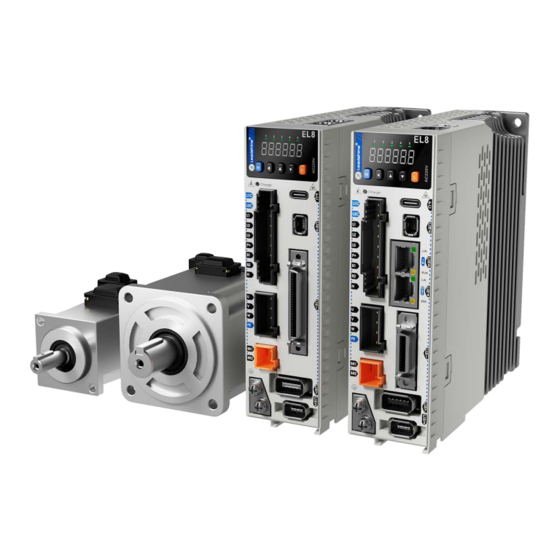
- Page 1 EL8-EC Series AC Servo Drive User Manual...
- Page 2 User Manual Of EL8-EC** AC Servo Foreword Thank you for purchasing Leadshine EL8-EC series AC Servo drives. This manual will provide information on the EL8-EC series servo products regarding product safety & specifications, installations & wiring, tuning & problem diagnostics.
- Page 3 User Manual Of EL8-EC** AC Servo Transportation Caution Caution Please provide storage and transportation under protected conditions. Do not stack the products too high up to prevent toppling. The product should be packaged properly during transportation, Do not hold the product by the cable, motor shaft or encoder while transporting it. ...
- Page 4 User Manual Of EL8-EC** AC Servo Tuning and running Caution Caution Make sure the wirings of servo drive and servo motor are installed and fixed properly before powering on. On the first time tuning of the product, it is recommended to run unloaded until all the parameter settings are confirmed to prevent any damage to the product or machine.
-
Page 5: Warranty Information
If available, please send product back in original packaging or make sure it is well packaged to prevent any damage to the product during shipping. Leadshine Technology Co.,Ltd. and its certified sales channel reserved the final right of the interpretation of the warranty information. -
Page 6: Table Of Contents
User Manual Of EL8-EC** AC Servo TABLE OF CONTENTS WARRANTY INFORMATION ........................5 CHAPTER 1 INTRODUCTION ....................... 11 1.1 P ........................11 RODUCT NTRODUCTION 1.2 M ........................ 12 ODEL UMBER TRUCTURE 1.2.1 Servo Drive ..........................12 1.2.2 Servo motor ..........................13 1.3 S .................... - Page 7 User Manual Of EL8-EC** AC Servo 3.2 P ......................... 69 ARAMETER UNCTION 3.2.1 Class 0 Basic Settings ......................69 【 】 3.2.2 Class 1 Gain Adjustments ....................78 【 】 3.2.3 Class 2 Vibration Suppression ................... 86 【 】 3.2.4 Class 3 Velocity Control .....................
- Page 8 User Manual Of EL8-EC** AC Servo 5.7.1 Common Functions of Torque Mode ..................223 5.7.2 Cyclic Synchronous Torque Mode (CST) ................. 224 5.7.3 Profile Torque Mode (PT) ....................... 225 CHAPTER 6 APPLICATION ......................... 227 6.1 G ..........................227 DJUSTMENT 6.2 I ......................
- Page 9 User Manual Of EL8-EC** AC Servo 7.4.1 Network structure of EL8-EC ....................294 7.4.2 Object dictionary ........................295 7.4.3 Service Data Object (SDO) ..................... 295 7.4.4 Process Data Object (PDO) ....................295 7.5 N ........................298 ETWORK STATUS DISPLAY CHAPTER 8 WARNING AND ALARM ....................300 8.1 S ........................
- Page 10 User Manual Of EL8-EC** AC Servo List of abbreviations used in this manual Abbreviation Full Form Bit/S Bit Per Second CANopen Over EtherCAT Init To Pre-Operation Pre-Operational To Init Pre-Operational To Safe-Operational Safe-Operational To Pre-Operational Safe-Operational To Operational Operational To Safe-Operational Operational To Init Safe-Operational To Init Versus...
-
Page 11: Chapter 1 Introduction
Safe Torque Off (STO) function, Gantry synchronization, full closed loop functionalities and much more. First time user of the EL8-EC series servo products can refer to this manual for more information on this product that cannot be covered in this short introduction. For further technical support, please do contact us or any local Leadshine certified retailers on Contact Us page. -
Page 12: Model Number Structure
1PH/3PH 200VAC – 240VAC, 10.5A,50/60Hz Main power input : Input voltage, current, frequency 1PH 200VAC – 240VAC, 1A,50/60Hz Control power input : Output (UVW): Output voltage, 0 -240V,4A, 0 - 2500Hz current, frequency China Leadshine Technology Co.Ltd Serial Number S/N:38AA1158200001MS10 www.leadshine.com Website... -
Page 13: Servo Motor
User manual of EL8-EC***F AC Servo 1 .2.2 Servo motor 8 0 B ELM1 0400 M (1)Series No. ELM1 ELM1 Series servo motor (9Motor Connector ELM2 ELM2 Series servo motor Direct Connector Blank Aviation Connector (2)Inertia Ratio (8)Voltage 220VAC Blank Medium 380VAC High... -
Page 14: Servo Drive Technical Specifications
User manual of EL8-EC***F AC Servo 1 .3 Servo Drive Technical Specifications 1 3 B EL8-EC1000F EL8-EC Series Driver EL8-EC400F EL8-EC750F EL8-EC1000F EL8-EC2000F Power Rating 400W 750W 1000W Rated Current (A) Coming Soon! Peak Current (A) 16.9 21.2 Control circuit power supply... - Page 15 User manual of EL8-EC***F AC Servo Cyclic Synchronous Torque Mode (CST) Control Features IGBT SVPWM sinusoidal wave drive Drive Mode Feedback Method Encoder: RS485 Protocol Standardized Quick tuning of servo driver parameters can be achieved through PC tuning Parameters tools. Easy-to-use One-click tuning, Single parameter tuning, Black box, Zero tracking control Mechanical resonance suppression.
-
Page 16: Servo Drive Ports And Connectors
User manual of EL8-EC***F AC Servo 1 .4 Servo Drive Ports and Connectors 1 4 B CN3 / CN4:RS485 Communication Port Front Panel Power on indicator light USB Type-C Main Power Supply CN6:STO AC220V Motor connectors CN1:I/O Signal Holding Brake 24VDC (BR+、BR-)... - Page 17 User manual of EL8-EC***F AC Servo Parts & Connectors Description Including a LED display and 5 buttons. LED display is used to display servo driver status and parameter settings. 5 buttons: ◀ :To switch between different modes and parameters Front Panel :Switch between value ▲...
-
Page 18: Motor Ports And Connectors
User manual of EL8-EC***F AC Servo 1 .5 Motor ports and connectors 1 5 B Motors with aviation connectors ② Power connector ① Encoder connector ③ Motor flange ④Installation screw holes ⑤ Motor shaft Motors with direct connectors Encoder ① Power connector ②... -
Page 19: Chapter 2 Installation & Wiring
User manual of EL8-EC***F AC Servo C hapter 2 Installation & Wiring 2 .1 Servo Drive Installation 1 6 B 2 .1.1 Servo drive installation environment 8 1 B Storage: -20-80℃ (Condensation free); Temperature Installation: 0-55℃ (Not frozen) Humidity Under 90%RH (Condensation free) Altitude Up to 1000m above sea level Vibration... - Page 20 User manual of EL8-EC***F AC Servo Space requirement for installation In order to ensure efficient heat dissipation, please leave at least 10mm installation space in between drivers. If drivers need to be mounted compactly, please leave at 1mm of installation space. Please keep in mind that under such conditions, the drivers can only run at 75% of actual load rate.
-
Page 21: Servo Motor Installation
User manual of EL8-EC***F AC Servo 2.2 Servo Motor Installation 2.2.1 Installation conditions Installation conditions may affect the lifespan of a motor Please keep away from corrosive fluid and combustibles. If dusty working environment is unavoidable, please use motors with oil seal. ... - Page 22 User manual of EL8-EC***F AC Servo Encoder & coupling During installation or removal of coupling, please do not hit the motor shaft with a hammer as it would cause damage to internal encoder. Please make sure to centralize the motor shaft and coupling, it might cause damage to motor or encoder due to vibration.
-
Page 23: El8-Ec Wiring Diagram
User manual of EL8-EC***F AC Servo 2.3 EL8-EC Wiring Diagram EL8-EC 220VAC Wiring Diagram Main power supply Single phase 220VAC Circuit breaker Turn on/off power supply. Cut off power supply when current overload Line filter To prevent CN8 :Analog Output/ electromagnetic interference Z-phase open collector output... - Page 24 User manual of EL8-EC***F AC Servo EL8-EC 220VAC Electrical Wiring Diagram Encoder 1ph/3ph Cable 220VAC Circuit breaker Line filter Contactor Motor power cable Connect B1 and B2 to use internal regenerative resistor ; If an external regenerative resistor is needed , connect it to P+ and B2 ,...
-
Page 25: Servo Drive Ports
User manual of EL8-EC***F AC Servo 2.4 Servo Drive Ports Port Description I/O Signal (50 pins) Motor encoder feedback input EtherCAT(IN)Communication Port EtherCAT(OUT)Communication Port RS422 Communication Port Safe Torque Off (STO) Encoder feedback input (External) Analog output/Z-phase open collector output X1/X2 Main/Control circuit power supply;... -
Page 26: Main/Control Circuit Power Supply X1
User manual of EL8-EC***F AC Servo 2.5 Main/Control circuit power supply X1 Label Explanation Remarks ① Optional isolated switching Control circuit L1 Control circuit power power supply; supply. Single phase ② Connecting to 380VAC will Control circuit L2 220VAC cause damage to driver; ③... -
Page 27: Main Power Supply Cable Selection
User manual of EL8-EC***F AC Servo 2.5.1 Main power supply cable selection Please connect to L1C/L2C (Control circuit) and L1/L2/L3 (Main power) to rated power supply voltage for the driver to operate under normal working condition. Driver will not function without both connected properly. Main power supply wire gauge Wire diameter (mm /AWG) -
Page 28: Single/Three Phase Power Supply Wiring Diagram
User manual of EL8-EC***F AC Servo 2.5.2 Single/Three phase power supply wiring diagram Single Phase 220VAC Single Phase 220VAC Contactor Line filter 伺服驱动器 Motor Encoder Start Stop Brake Relay BK-RY DO1+ Alarm (BRK-OFF+) relay Holding DO1- brake (BRK-OFF-) 24V Brake Warning indicator light ◆... -
Page 29: Motor Power Supply X2
Motor winding power cable Wire length available: 1.5m, 3m and 5m Connectors type available: AMP electrical connectors, aviation connectors, direct connectors (recommended) Please contact Leadshine sales team or any Leadshine certified local retailers for any customized needs. - Page 30 User manual of EL8-EC***F AC Servo *M*: Length of the cable Aviation connector(Frame size 130) CABLE-RZ*H(V1.1/V2.0) Motor side Driver side Pins Motor cable pin Motor Color Driver Green Black Yellow Motor side Direct connector(Frame size 80 or below)CABLE-RZH*M*-114-TS without holding brake Motor side Driver side Driver cable pin...
-
Page 31: Holding Brake X3
User manual of EL8-EC***F AC Servo 2.7 Holding Brake X3 Label Explanation Connect to external power supply 24v BR+(BR1) Brake positive terminal negative terminal Brake negative terminal Connect to motor brake terminal 0V BR- (BR2) -
Page 32: Holding Brake Wiring Diagram
User manual of EL8-EC***F AC Servo 2.7.1 Holding brake wiring diagram Holding brake is activated when servo drive is not powered on to prevent axis from moving due to gravitational pull or other external forces by locking the motor in place. Usually used on axis mounted vertically to the ground so that the load would not drop under gravitational force when the driver is powered off or when alarm occurs. -
Page 33: Cable Selection For Motor With Holding Brake
User manual of EL8-EC***F AC Servo 2.7.2 Cable selection for motor with holding brake Aviation connector (Frame size 80 or below) CABLE-RZSH*M*-113-TS Winding cable with holding brake Motor side Driver side Motor cable pin Pins Motor Color Driver Blue Black Yellow- green Black... - Page 34 User manual of EL8-EC***F AC Servo Mechanical noise might exist when motor with holding brake is in operation but it doesn’t affect the functionality of the motor. When the holding brake circuit is closed (holding brake deactivated), there might be magnetic flux leakage.
-
Page 35: I/Osignal Cn1
User manual of EL8-EC***F AC Servo 2.8 I/O signal CN1 EL8-EC series servo drives use SCSI 26-pin connector. Port Diagram Label Signal Description DI-COM Input Common digital input Digital input 1 Positive limit switch Negative limit switch HOME-SWITCH Homing switch... -
Page 36: Cable Selection For I/O Signal Port Cn1 And Encoder Feedback Port Cn2
User manual of EL8-EC***F AC Servo Pin terminals on motor side Motor side Driver side Frame 80 or Frame 130 (1394 6PIN) Frame 130 below (850w,1300w,1800w) Frame 1(Shielding) 1(Shielding) 1(Shielding) (3) (3) BAT+ (4) (2) BAT- 2.9.1 Cable selection for I/O signal port CN1 and encoder feedback port CN2 I/O signal cable To ensure I/O signal to not be affected by electromagnetic interference, a shielded... - Page 37 User manual of EL8-EC***F AC Servo Motor encoder cable and connector selection Aviation connector(Frame size 130)CABLE-7BM*HZ(V3.0) Motor side Driver side Motor cable pin Motor Driver Signal Frame Shielded BAT+ Motor side BAT- Direct connector(Frame size 80 or below)CABLE-BMH*M*-114-TS Incremental encoder Motor side Driver side Motor cable pin...
- Page 38 Direct connector(Frame size 80 or below)CABLE-BMAH*M*-124-TS Absolute encoder Motor side Driver side Motor cable pin Motor Driver Signal Frame Shielded BAT+ Motor side BAT- Battery box for absolute encoder EL8-EC series servo drives come with battery kit installed on the driver or on the encoder cable.
-
Page 39: Ethercat Communication Port Cn3/Cn4
User manual of EL8-EC***F AC Servo 2.10 EtherCAT communication port CN3/CN4 Port Diagram Signal Description EtherCAT Data sending 1, 9 E_TX+ positive terminal EtherCAT Data sending 2, 10 E_TX- negative terminal EtherCAT Data receiving 3, 11 E_RX+ positive terminal 4, 12 5, 13 EtherCAT Data receiving 6, 14... -
Page 40: Safe Torque Off (Sto) Port
User manual of EL8-EC***F AC Servo 2.11 Safe Torque Off (STO) Port Port Signal Description Remarks 24v power supply Connect to SF1 and SF2 when not in use. Do not use Reference ground to supply power. Control signal SF1+ positive input Control signal SF1-... - Page 41 User manual of EL8-EC***F AC Servo STO wiring diagram STO in use STO not in use Please disconnect 0V 24v power supply and 24V while in use only for STO, please do not use it for other purposes. SF1- SF1- 2.2K 2.2K SF1+...
-
Page 42: Encoder #2 (External) Cn7
User manual of EL8-EC***F AC Servo 2.12 Encoder #2 (External) CN7 Signal Description Power supply 5V Power supply ground Phase A+ pulse input Phase A- pulse input Phase B+ pulse input Phase B- pulse input Phase Z+ pulse input Phase Z- pulse input Shield grounding Frame External encoder pulse input... -
Page 43: Analog And Z-Phase Open Collector Output Cn8
User manual of EL8-EC***F AC Servo 2.13 Analog and Z-phase open collector output CN8 CN8 has 2 analog outputs and 1 Z-phase open collector output Port Diagram Signal Description Remarks Analog output 1 Signal ground Analog output 2 Signal ground Z-Phase open Only NPN Open... -
Page 44: Usb Type -Ctuning Port
User manual of EL8-EC***F AC Servo 2.14 USB Type-C tuning port EL8-EC series servo drive can be connected to PC for performance tuning, data monitoring and parameters modifying using a USB Type-C data cable. Can be done without the servo drive connecting to main power supply. -
Page 45: Regenerative Resistor Selection And Connections
Selection of regenerative resistor EL8-EC series servo drives are equipped with internal regenerative resistor. If an external resistor is needed, please refer to the table below. Internal regenerative resistor Minimum allowable Model no. - Page 46 User manual of EL8-EC***F AC Servo external regenerative resistor with higher power rating. If d14 is overly large or increasing too fast, reduce regenerative energy power rating or use an external regenerative resistor with higher power rating. If driver overvoltage alarm (Er120) occurs, please use an external regenerative resistor with lower resistance or connect another resistor in parallel.
- Page 47 User manual of EL8-EC***F AC Servo Theoretical selection of regenerative resistor Without external loading torque, the need for an external regenerative resistor can be determined as the flow chart below Start T is the time for velocity to reach Determine the max.
- Page 48 User manual of EL8-EC***F AC Servo Diagram below shows the acceleration and deceleration cycle periods and the regenerative torque that occurs during the process. V:Motor rotational velocity Rotational velocity :Deceleration time Motor Torque : Load torque Regenerative torque Steps to calculate capacity of regenerative resistor Steps Calculation Symbol...
- Page 49 User manual of EL8-EC***F AC Servo Servo drive: EL8-EC750F, Servo Motor: ACM2-08008H2. When T = 2s, rotational velocity = 3000rpm, load inertia is 5 times of motor inertia. Rotor Inertia Max. regenerative energy EL8-EC Drivers Servo motor (× 10 ) kg.m stored in capacitor Ec(J) 750W...
-
Page 50: I/O Signal
User manual of EL8-EC***F AC Servo Regenerative resistor connection If B1 and B2 are connected, internal regenerative resistor is now functional; if an external regenerative resistor is required, please disconnect B1 and B2 and connect P+ to B1 to prevent overcurrent. ... -
Page 51: Common Digital Input
User manual of EL8-EC***F AC Servo 2.16.2 Common digital input The internal circuit of common input is a bidirectional optocoupler which supports common anode and common cathode configurations. There are 2 types of outputs from master device: Relay output and Open Collector output as shown below. Driver internal circuit 12~24Vdvc DICOM... -
Page 52: Common Digital Output
User manual of EL8-EC***F AC Servo 2.16.3 Common digital output There are 3 digital outputs which are double-ended, having an isolated 24v power supply. Double-ended output DO1-DO3 Flyback diode required when DO1+ load is inductive 12~24Vdc DO1- DO2+ 12~24Vdc DO2- DO3+ 12~24Vdc DO3-... -
Page 53: Probe Input
39+38 are 2 double ended outputs. 2.16.4 Probe input EL8-EC series servo drives use DI5 and DI6 as probe input terminals. DI5/DI6 is default as probe function if no other function is assigned to them. Internal circuit is a bidirectional optocoupler. -
Page 54: Digital Input Signal Settings
User manual of EL8-EC***F AC Servo 2.16.6 Digital Input Signal Settings CN1 PIN Signal Parameter Default function Default status DI-COM Common DI Pr4.00 Normally open Pr4.01 Normally open Pr4.02 Normally open Pr4.03 HOME-SWITCH Normally open Pr4.04 Normally open Pr4.05 Normally open Pr4.06 Normally open Pr4.07... -
Page 55: Measures Against Electromagnetic Interference
User manual of EL8-EC***F AC Servo 2.17 Measures against electromagnetic interference To reduce interference, please take the following measures: I/O signal cable > 3m; Encoder cable > 20m ①Grounding resistance > 100Ω Use cable with larger diameter for grounding ②When there are multiple drivers connected in parallel, PE terminal of the main power supply and ground terminal of servo drives must be connected to copper ground bar in the electrical cabinet and the copper ground bar needs to be... -
Page 56: Using Line Filter
User manual of EL8-EC***F AC Servo 2.11.2 Using line filter To reduce interference from main power supply cable and to prevent from affecting other sensitive components around the servo drive, please choose a line filter based on actual supply current. Please do be aware of the following mistake when installing a line filter. Do not band the main power supply cable together. -
Page 57: Chapter 3 Parameter
User manual of EL8-EC***F AC Servo Chapter 3 Parameter 3.1 Parameter List Panel Display as follows: Parameter Valid Mode CSP: Valid in cyclic synchronous position mode CSV: Valid in cyclic synchronous velocity mode CST: Valid in cyclic synchronous torque mode HM: Valid in homing mode PP: Valid in profile position mode PV: Valid in profile velocity mode... - Page 58 User manual of EL8-EC***F AC Servo EtherCAT Panel Label Class Activation Valid Mode Address display Regenerative resistor 2017h PR_017 Immediate power rating Friction compensation 2019h PR_019 Immediate setting EtherCAT slave ID 2023h PR_023 After restart Source of slave ID 2024h PR_024 After restart Synchronous compensation...
- Page 59 User manual of EL8-EC***F AC Servo EtherCAT Panel Label Class Activation Valid Mode Address display Torque feed forward filter 2113h PR_113 Immediate time constant Position control gain 2115h PR_115 Immediate switching mode Position control gain 2117h PR_117 Immediate switching level Hysteresis at position 2118h PR_118...
- Page 60 User manual of EL8-EC***F AC Servo EtherCAT Panel Label Class Activation Valid Mode Address display MFC type 2250h PR_250 Immediate Velocity feedforward Immediate 2251h PR_251 compensation coefficient Torque feedforward 2252h PR_252 Immediate compensation coefficient Dynamic friction 2253h PR_253 Immediate compensation coefficient Overshoot time coefficient 2254h PR_254...
- Page 61 User manual of EL8-EC***F AC Servo EtherCAT Panel Label Class Activation Valid Mode Address display Zero speed 2434h PR_434 Immediate Velocity coincidence range 2435h PR_435 Immediate Arrival velocity 2436h PR_436 Immediate Motor power-off delay time 2437h PR_437 Immediate Delay time for holding brake 2438h PR_438 Immediate...
- Page 62 User manual of EL8-EC***F AC Servo EtherCAT Panel Label Class Activation Valid Mode Address display Overload level setting 2512h PR_512 Immediate Overspeed level settings 2513h PR_513 Immediate I/O digital filter 2515h PR_515 Immediate Counter clearing input 2517h PR_514 Immediate mode Position unit settings 2520h PR_520...
-
Page 63: Manufacturer Parameter
User manual of EL8-EC***F AC Servo EtherCAT Panel Label Class Activation Valid Mode Address display Torque command additional 2607h PR_607 Immediate value Positive direction torque 2608h PR_608 Immediate compensation value Negative direction torque 2609h PR_609 Immediate compensation value Current response settings 2611h PR_611 Immediate... - Page 64 User manual of EL8-EC***F AC Servo Sync0 Drift 65535 watchdog counter Sync0 Drift 73C alarm threshold value, set 65535 watchdog limit to zero shield SM2 watchdog 65535 counter SM2 Watchdog 73A alarm threshold value, set 65535 limit to zero shield Application layer SM2/Sync0 watchdog counter...
- Page 65 User manual of EL8-EC***F AC Servo 1:As normal, continue homing process synchronization 5400 1000 cycle minimum value synchronization 5400 10000 4000 20000 cycle maximum value Absolute encoder multiturn number Encoder single Pulse turn position Encoder feedback Pulse position 32 bit low Encoder feedback position 32 bit Pulse...
-
Page 66: Motion Parameter Starting With Object Dictionary 6000
℃ User manual of EL8-EC***F AC Servo Temperature Power on time 3.1.3 Motion parameter starting with object dictionary 6000 Index Label Unit Mode Sub-index Default 603F Error code 0xFFFF 6040 Control word 0xFFFF 6041 Status word 0xFFFF Quick stop option code 605A Motor deceleration-stopping 605B... - Page 67 User manual of EL8-EC***F AC Servo 6074 Internal command torque 0.001 -32768 32767 214748 Motor current rating 6075 3000 3647 6077 0.1% Actual torque -32768 32767 214748 6079 DC bus voltage 3647 Comman -21474 214748 CSP/P 607A Target position d unit 83648 3647 Comman...
- Page 68 User manual of EL8-EC***F AC Servo 60B8 Probe function 0xFFFF Probe status 60B9 0xFFFF Probe 1 rising edge Comman -21474 214748 60BA d unit 83648 3647 captured position Probe 1 falling edge Comman -21474 214748 60BB d unit 83648 3647 captured position Probe 2 rising edge Comman...
-
Page 69: Parameter Function
User manual of EL8-EC***F AC Servo 3.2 Parameter Function Panel Display as follows: Parameter valid under following modes CSP: Cyclic synchronous position mode CSV: Cyclic synchronous velocity mode CST: Cyclic synchronous torque mode HM: Homing mode PP: Profile position mode PV: Profile velocity mode PT: Profile torque mode F: All modes... - Page 70 User manual of EL8-EC***F AC Servo Real time Auto Gain Label Valid Mode Adjusting Pr0.02 Range 0x0~0xFFF Unit — Default 0x001 Index 2002h Activation Immediate Set up the mode of the real time auto gain adjusting. Data Category Settings Application bits Used to set motion setting mode, which can be selected according to the motion characteristics or setting requirements.
- Page 71 User manual of EL8-EC***F AC Servo The setting type combination is a hexadecimal standard, as follows: Setting type Application type combination 0X000 Rigid structure Manual 0X001 Rigid structure +Standard 0X002 Rigid structure +Positioning 0X010 High inertia + Manual 0X011 High inertia + Standard 0X012 High inertia + Positioning 0X020...
- Page 72 User manual of EL8-EC***F AC Servo Command polarity Label Mode inversion Pr0.06 Range 0 ~ 1 Unit — Default Index 2006h Activation After restart Used to change the rotational direction of the motor. Set value Details Polarity of the command is not inversed. The direction of rotation is consistent with the polarity of command.
- Page 73 User manual of EL8-EC***F AC Servo Pulse sequence 【3】 + Directional symbol 90°phase difference 2 phase pulse (Phase A+Phase B) CW pulse sequence + CCW pulse sequence Pulse sequence + Directional symbol Command pulse input signal max. frequency and min. duration needed Max.
- Page 74 User manual of EL8-EC***F AC Servo Pulse output logic Label Mode inversion Pr0.12 Range Default Index 2012 Activation After restart To set phase B logic and output source from encoder pulse output. Pulse output logic inversion Pr0.12 Phase B logic CW direction CCW direction Not inverted...
- Page 75 User manual of EL8-EC***F AC Servo Used when travel distance is within 1 revolution of the encoder. Data overflow will trigger alarm. 5: Clear multiturn alarm and activate multiturn absolute function. Will switch to multiturn mode once alarm cleared, if remains at 5 after 3s, please solve according to Er153. 9: Clear multiturn position, reset multiturn alarm and activate multiturn absolute function.
- Page 76 User manual of EL8-EC***F AC Servo Synchronous Label Mode compensation time 1 Pr0.25 Range 1~100 Unit 0.1us Default Index 2025h Activation After restart Synchronous dithering compensation range. Used for master device with poor synchronization. Synchronous Label Mode compensation time 2 Pr0.26 Range 1~2000...
- Page 77 User manual of EL8-EC***F AC Servo Label External encoder type Mode Pr0.31 Range Unit Default Index 2031h Activation Immediate Set value Description 【0】 ABZ encoder Reserved for future upgrades Label External encoder direction Mode Pr0.32 Range Unit Default Index 2032h Activation Immediate Set value...
-
Page 78: Class 1】Gain Adjustments
User manual of EL8-EC***F AC Servo External encoder frequency Label Mode divider denominator Pr0.36 Range Unit Default Index 2036h Activation After restart When Pr0.37 = 0, External encoder feedback pulse count per revolution = Pr0.36 External encoder feedback Label Mode pulse count per revolution Pr0.37 Range... - Page 79 User manual of EL8-EC***F AC Servo Activation Immediate To determine the responsiveness of the velocity loop. If inertia ratio of Pr0.04 is uniform with actual inertia ratio, velocity loop responsiveness = Pr1.01. To increase position loop gain and improve responsiveness of the whole system, velocity loop gain must be set at higher value.
- Page 80 User manual of EL8-EC***F AC Servo Torque Filter Time Label Mode Constant 0~250 Pr1.04 Range Unit 0.01ms Default Index 2104h Activation Immediate To set torque command low-pass filter, add a filter delay time constant to torque command and filter out the high frequencies in the command. Often used to reduce or eliminate some noise or vibration during motor operation, but it will reduce the responsiveness of current loop, resulting in undermining velocity loop and position loop control.
- Page 81 User manual of EL8-EC***F AC Servo Torque Filter Time Label Mode Constant Pr1.09 Range 0~2500 Unit 0.01ms Default Index 2109h Activation Immediate Position loop, velocity loop, velocity detection filter, torque command filter eachhave 2 pairs of gain or time constant (1st and 2nd). Velocity feed forward Label Mode...
- Page 82 User manual of EL8-EC***F AC Servo Torque feed forward Label Mode filter time constant 0~640 Pr1.13 Range Unit 0.01ms Default Index 2113h Activation Immediate Low pass filter to eliminate abnormal or high frequencies in torque feed forward command. Usually used when encoder has lower resolution or precision. Noise reduces if torque feed forward filter time constant is set higher but position deviation will increase at acceleration varied points.
- Page 83 User manual of EL8-EC***F AC Servo Hysteresis Level Velocity Valid for position control. Switch to 2 gain when position deviation absolute value larger than (level + hysteresis)[pulse] Switch to 1 gain when position deviation absolute value smaller than (level-hysteresis)[pulse] Large position deviation Velocity Level...
- Page 84 User manual of EL8-EC***F AC Servo Hysteresis Level Velocity Feedback Valid for position control. gain if position command ≠ 0 Switch to 2 Switch to 1 gain if positional command = 0 throughout the duration of delay time and absolute value of actual velocity remains smaller than (level - hysteresis) (r/min) Pending position command...
- Page 85 User manual of EL8-EC***F AC Servo Hysteresis at position Label Mode control switching 0~2000 Mode Pr1.18 Range Unit Default Index 2118h dependent Activation Immediate To eliminate the instability of gain switching. Used in combination with Pr1.17 using the same unit. If level<...
-
Page 86: Class 2】Vibration Suppression
User manual of EL8-EC***F AC Servo 3.2.3【Class 2】Vibration Suppression Adaptive filtering mode Label Mode settings Pr2.00 Range Unit Default Index 2200h Activation Immediate Set value Explanation Adaptive filter: invalid Parameters related to 3 and 4 notch filter remain unchanged Adaptive filter: 1 filter valid 1 adaptive filter becomes valid. - Page 87 User manual of EL8-EC***F AC Servo Label notch depth selection Mode Range 0~99 Unit Default Index 2203h Pr2.03 Activation Immediate Set notch depth for 1 resonant notch filter. Under normal circumstances, please use factory default settings. If resonance is under control, in combination with Pr2.01 and Pr2.02, Pr2.03 can be reduced to improve current loop responsiveness which allows higher mechanical stiffness settings.
- Page 88 User manual of EL8-EC***F AC Servo notch bandwidth Label Mode selection Pr2.08 Range 0~20 Unit Default Index 2287h Activation Immediate Set notch bandwidth for 3 resonant notch filter. Under normal circumstances, please use factory default settings. Label notch depth selection Mode Range 0~99...
- Page 89 User manual of EL8-EC***F AC Servo Position command Label Mode smoothing filter Pr2.22 Range 0~32767 Unit 0.1ms Default Index 2222h Activation Stop axis To set time constant of 1 time delay filter of position command. To set time constant of 1 time delay filter, according to target velocity Vc square wave command as show below.
- Page 90 User manual of EL8-EC***F AC Servo Label Position command FIR filter Mode Pr2.23 Range 0~10000 Unit 0.1ms Default Index 2223h Activation Disable axis As shown below, when target velocity Vc square wave command reaches Vc, it becomes trapezoidal wave after filtering. Position Position command Velocity...
- Page 91 User manual of EL8-EC***F AC Servo Label resonant Q value Mode 0~1000 Range Unit Default Index 2232h Pr2.32 Activation Immediate To set notch Q value of 5 resonant notch filter Label anti-resonant frequency Mode 50~4000 Range Unit Default 4000 Index 2233h Pr2.33 Activation...
- Page 92 User manual of EL8-EC***F AC Servo Label anti-resonant frequency Mode 50~4000 Range Unit Default 4000 Index 2237h Pr2.37 Activation Immediate To set zero-valued eigenfrequency of 6 resonant notch filter. Pr2.37 corresponds to machine-specific anti-resonant frequency. Label anti-resonant Q value Mode Range 0~9900 Unit...
- Page 93 User manual of EL8-EC***F AC Servo Velocity feedforward Label Mode compensation coefficient -10000~ Pr2.51 Range Unit Default Index 2251h 10000 Activation Immediate To compensate for velocity feedforward Torque feedforward Label Mode compensation coefficient -10000~ Pr2.52 Range Unit Default Index 2252h 10000 Activation Immediate...
-
Page 94: Class 3】Velocity Control
User manual of EL8-EC***F AC Servo Overshoot suppression Label Mode gain Pr2.55 Range 0~1000 Unit Default Index 2255h Activation Immediate Suppression improves with larger set value but might affect the performance of MFC. Please use with caution for any value above 100. 3.2.4【Class 3】Velocity Control Label Acceleration time settings... - Page 95 User manual of EL8-EC***F AC Servo Sigmoid Label acceleration/deceleration Mode settings Pr3.14 Range 0~1000 Unit Default Index 2314h Activation Axis disable To set sigmoid acceleration and deceleration turning point in accordance to Pr3.12 and Pr3.13. Velocity (RPM) Target velocity ta=Vc/1000 PA3.12 1ms td=Vc/1000 PA3.13 1ms ts=Pr3.14 1ms Please set according to...
- Page 96 User manual of EL8-EC***F AC Servo Zero speed clamp static Label Mode time Pr3.23 Range 0~32767 Unit Default Index 2323h Activation Immediate To set delay time for zero speed clamp. To prevent creeping at low speed, velocity command forced to 0 when velocity goes under Pr3.16 after time set in Pr3.23 Position comparison 1-42 Label...
-
Page 97: Class 4】I/O Interface Setting
User manual of EL8-EC***F AC Servo =1:Flipping mode 26~28 Reserved Frequency divider Phase A output Frequency divider Phase B output Frequency divider Phase Z output Position comparison x & y Label Mode attributes value Pr3.75~ 0x0~0xFF 2375h- Range Unit Default Index Pr3.94 FFFFFF... - Page 98 User manual of EL8-EC***F AC Servo Activation Immediate Label Input selection DI7 Mode Range 0x0~0xFF Unit — Default Index 2406h Pr4.06 Activation Immediate Label Input selection DI8 Mode Range 0x0~0xFF Unit — Default Index 2407h Pr4.07 Activation Immediate Digital input DI allocation using hexadecimal system Set value 0x60FD (bit...
- Page 99 User manual of EL8-EC***F AC Servo External brake released BRK-OFF Positioning completed At-speed AT-SPEED Torque limit signal Zero speed clamp detection Velocity coincidence V-COIN Position command ON/OFF P-CMD Velocity limit signal V-LIMIT Velocity command ON/OFF V-CMD Servo status SRV-ST Homing done HOME-OK Position comparison CMP-OUT...
- Page 100 User manual of EL8-EC***F AC Servo Label Analog filter 2 overvoltage Mode Range 0~100 Unit Default Index 2427h Pr4.27 Activation Immediate When Pr4.27 = 0, Pr4.27 invalid. Er270 might occur when the input voltage of AI1 is higher than the voltage after zero drift correction. Positioning complete Label...
- Page 101 User manual of EL8-EC***F AC Servo Label Zero speed Mode 1~200 Range Unit Default Index 2434h Pr4.34 Activation Immediate To set threshold value for zero speed clamp detection. Zero speed clamp detection (ZSP) output signal valid when motor speed goes under the value set in Pr4.34 Disregard the direction of rotation, valid for both directions.
- Page 102 User manual of EL8-EC***F AC Servo Label Arrival velocity (AT-speed) Mode Range 10~2000 Unit Default 1000 Index 2436h Pr4.36 Activation Immediate When motor velocity > Pr4.36, AT-speed output signal is valid. Detection using 10RPM hysteresis. Label Motor power-off delay time Mode Range 0~3000...
- Page 103 User manual of EL8-EC***F AC Servo SRV_ON Brake released (BRK_ON) Brake BRK_OFF Motor Power Released Actual holding Braked Braked brake status Motor Velocity *1: Delay time set in Pr4.38 *2: Delay time from the moment BRK_OFF signal is given until actual holding brake is released or BRK_ON signal is given until actual holding brake is activated.
- Page 104 User manual of EL8-EC***F AC Servo Label Emergency stop function Mode Range Unit Default Index 2443h Pr4.43 Activation Immediate 0:Emergency stop is valid, servo driver will be forced to STOP and alarm occurs. 1:Emergency stop is invalid, servo driver will not be forced to STOP. Label AO1 output mode Mode...
- Page 105 User manual of EL8-EC***F AC Servo To set the amplification of AO1, actual voltage output = amplification x theoretical voltage Label AO1 communication setting Mode -10000~10 Range Unit Default Index 2467h Pr4.67 Activation Immediate Available when AO1 = 0xB, AO1 output = output setting of Pr4.67 Label AO1 offset Mode...
- Page 106 User manual of EL8-EC***F AC Servo ··· Please refer to Pr4.12 for other signal channels Label AO2 amplification Mode -10000~10 Range Unit Default Index 2471h Pr4.71 Activation Immediate To set the amplification of AO2, actual voltage output = amplification x theoretical voltage Label AO2 communication setting Mode -10000~10...
-
Page 107: Class 5】Extension Settings
User manual of EL8-EC***F AC Servo Range 0~100 Unit Default Index 2478h Activation Immediate To select warning signal for warning indicator light 1 Set value Signal 【0】 None Negative limit Battery low voltage Overload Torque limit Positive limit other Reserved During normal operation, warning indicator light will be lighted in a cycle. - Page 108 User manual of EL8-EC***F AC Servo Label Main power-off detection time Mode Range 50~2000 Unit Default Index 2509h Pr5.09 Activation Immediate To set duration time for detection of main power-off or low voltage supply. Servo-off Label Mode alarm mode Pr5.10 Range Unit Default...
- Page 109 User manual of EL8-EC***F AC Servo Overload level Label Mode setting Pr5.12 0~11 Range Unit Default Index 2512h Activation Immediate If Pr5.12 = 0, overload level = 115% Use only when overload level degradation is needed. Label Overspeed level settings Mode Defaul Range...
- Page 110 User manual of EL8-EC***F AC Servo Set value Unit Encoder unit Command unit 0.0001rev Command unit: Pulse from host Encoder unit: Pulse from encoder Pr5.20 only changes the unit use on host tracing function, has no relation with any position related parameters.
- Page 111 User manual of EL8-EC***F AC Servo Sum of command Single turn Synchronous period pulse position No. of synchronous Maximum torque Multiturn position during motion loss Communication Synchronous type axis address Whether DC is Encoder position Control mode deviation running or not Acceleration/Deceler Motor electrical I/O signal status...
- Page 112 User manual of EL8-EC***F AC Servo Activation After restart Polarity Description 0 = Positive Z polarity setting of frequency divider output Bit0 and position comparison 1 = Negative 0 = Positive Only valid in position comparison. Bit1 Polarity setting when phase A frequency 1 = Negative divider as position comparison output 0 = Positive...
- Page 113 User manual of EL8-EC***F AC Servo External encoder overspeed Label Mode feedback threshold Pr5.45 Range 0~10000 Unit Default Index 2545h Activation Immediate To set external encoder overspeed feedback threshold Label Vent overload level Mode Range 0~115 Unit Default Index 2546h Pr5.46 Activation Immediate...
- Page 114 User manual of EL8-EC***F AC Servo Position comparison output delay Label Mode time compensation Pr5.73 0.1μs Default Range -10000~10000 Unit Index 2573h Activation After restart To set delay time compensation for delay due to DO/ frequency divider Position comparison starting Label Mode point...
-
Page 115: Class 6】Other Settings
User manual of EL8-EC***F AC Servo 3.2.7【Class 6】Other settings Encoder zero position Label Mode compensation Pr6.01 Range 0~360 Unit ° Default Index 2601h Activation After restart Angle of the encoder after zero position calibration trial torque Label Mode command Pr6.03 Range 0~350 Unit... - Page 116 User manual of EL8-EC***F AC Servo Label Position 3 gain valid time Mode Pr6.05 Range 0~10000 Unit 0.1ms Default Index 2605h Activation Immediate To set time for 3 gain to be valid When not in use, set Pr6.05=0, Pr6.06=100 Position gain scale Label...
- Page 117 User manual of EL8-EC***F AC Servo Label Negative direction torque Mode compensation value Pr6.09 Range -100~100 Unit Default Index 2609h Activation Immediate To reduce the effect of mechanical friction in the movement(s) of the axis. Compensation values can be set according to needs for both rotational directions. Applications: 1.
- Page 118 User manual of EL8-EC***F AC Servo Label Trial run waiting time Mode Range 0~30000 Unit Default Index 2621h Pr6.21 Activation Immediate JOG (Position control) : Waiting time after each motion Label No. of trial run cycles Mode Range 0~32767 Unit Default Index 2622h...
- Page 119 User manual of EL8-EC***F AC Servo Absolute value rotation Label Mode mode denominator setting Pr6.54 Range 0~32766 Unit Default Index 2654h Activation After restart To set denominator of absolute encoder in rotational mode. When Pr0.15 = 2 and use in combination with Pr6.54: Feedback load position 6064= x Electronic gear ratio Blocked rotor alarm torque...
-
Page 120: Class 7】Factory Settings
User manual of EL8-EC***F AC Servo Absolute multiturn data Label Mode upper limit Pr6.63 Range 0~32766 Unit Default Index 2663h Activation After restart To set upper limit of multiturn data with absolute encoder set as rotational mode. When Pr0.15 = 2 and use in combination with Pr6.54: Feedback load position 6064= x Electronic gear ratio 3.2.8【Class 7】Factory settings... -
Page 121: Parameters Function
User manual of EL8-EC***F AC Servo Label External grating ruler precision Mode Range 1-1000000 Unit Default Property Pr7.54 Activation After restart Data length 16 bit To select external grating ruler precision 3.3 402 Parameters Function Panel Display as follows: ... - Page 122 User manual of EL8-EC***F AC Servo Label Description Start 1 - valid, 0 - invalid Main circuit power on 1 - valid, 0 - invalid Quick stop 0 - valid,1 - invalid Servo running 1 - valid, 0 - invalid Running mode related Related to each servo running mode Reset resettable fault alarm.
- Page 123 User manual of EL8-EC***F AC Servo 2 :Motor decelerates and stops through 6085h. Status: Switch on disable, axis disabled. 3 :Motor decelerates and stops through 60C6h. Status: Switch on disable, axis disabled. 5 :Motor decelerates and stops through 6084h. Status: Quick stop 6 :Motor decelerates and stops through 6085h.
- Page 124 User manual of EL8-EC***F AC Servo 1 :Motor decelerates and stops through 609Ah 0 :To stop motor through Pr5.06, Pr5.06 = 0(Emergency stop), Pr5.06=1(Free stop) 1 :Motor decelerates and stops through 6087h Pause-stopping mode INT 16 Label Unit Structure Type Index selection 605Dh...
- Page 125 User manual of EL8-EC***F AC Servo Operation mode Label Unit Structure Type Int 8 Index selection 6060h Access Mapping RPDO Mode Range 1~11 Default Mode Abbr. Profile position mode Profile velocity mode profile Torque mode Homing mode Cyclic synchronous position mode Cyclic synchronous velocity mode Cyclic synchronous torque mode Label...
- Page 126 User manual of EL8-EC***F AC Servo Actual position Comman Label Unit Structure Type Int 32 feedback d unit Index -21474836 6064h Mappin 48~214748 Access Range Default 3647 Reflects user’s real time absolute position 6064h*Gear ratio = 6063h Position deviation Comman UInt Label Unit...
- Page 127 User manual of EL8-EC***F AC Servo Comman Velocity feedback Int 32 Label Unit Structure Type d unit/s Index -21474836 606Ch Mappin Access CSV/PP Range 48~214748 Default 3647 Reflects user’s internal command velocity feedback value Comma UInt Velocity window Label Unit Structure Type nd unit/s...
- Page 128 User manual of EL8-EC***F AC Servo UInt Maximum torque 0.1% Label Unit Structure Type Index 6072h 0~6553 Access Mapping RPDO Mode F Range Default 3000 To set max. torque for servo driver. Limited by motor max. torque. UInt Label Maximum current Unit 0.1% Structure...
- Page 129 User manual of EL8-EC***F AC Servo Homing position Command Label Unit Structure Type offset unit Index -21474836 607Ch Mappin Access Range 47~214748 Default 3647 To set position offset to compensate for the deviation of mechanical origin from motor origin under homing Command Structur...
- Page 130 User manual of EL8-EC***F AC Servo Maximum protocol Comman Label Unit Structure VAR Type UInt 32 velocity d unit/s Index 0~214 607Fh Mappin PP/HM/P 21474836 RPDO 74836 Access Mode Range Default V/CST To set maximum allowable velocity. Limited by 6080. Maximum motor Label Unit...
- Page 131 User manual of EL8-EC***F AC Servo Label Torque slope Unit %1/s Structure VAR Type UInt 32 Index 1~214 Mappin 6087h RPDO 74836 5000 Access Mode Range Default To set values for tendency torque command Label Encoder resolution Unit Encoder unit Structure VAR Type UInt 32...
- Page 132 User manual of EL8-EC***F AC Servo gone Direction Deceleration point Home Before Z-signal Negative Negative limit switch Motor Z-signal Negative limit switch falling edge Positive Positive limit switch Motor Z-signal Positive limit switch falling edge Positive Homing switch Motor Z-signal Falling edge on same side of homing switch Positive...
- Page 133 User manual of EL8-EC***F AC Servo Homing acceleration Command Label Unit Structure VAR Type UInt 32 /deceleration unit/s² Index 1~214 609Ah Mappin 74836 500000 Access Mode Range Default To set acceleration and deceleration used in homing Command Structur Label Position feedforward Unit Type Int 32...
- Page 134 User manual of EL8-EC***F AC Servo Structur Label Probe function Unit Type UInt 16 Index 60B8h 0x0-0xFFF Access Mapping RPDO Mode Range Default Description Details Probe 1 0--Disable 1--Enable 0--Single trigger, triggered only when trigger signal Probe 1 trigger mode is valid 1—Continuous trigger Probe 1 trigger signal selection...
- Page 135 User manual of EL8-EC***F AC Servo Probe status UInt 16 Label Unit Structure Type Index 00x-0xF Defaul 60B9h Access Mapping TPDO Mode Range Definition Details Probe 1 0--Disable 1--Enable Probe 1 rising edge latching 0—Rising edge not latched 1—Rising edge latched Probe 1 falling edge latching 0—Falling edge not latched 1—Falling edge latched...
- Page 136 User manual of EL8-EC***F AC Servo 3647 Shows position feedback at falling edge of probe 2 signal Protocol maximum Command Structur Label Unit Type UInt 32 acceleration unit/s² Index 60C5h Mappin 1~2147483 100000 RPDO Mode F Access Range Default To set upper limit of acceleration. Protocol maximum Command Structur...
- Page 137 User manual of EL8-EC***F AC Servo Max. torque in positive Structur 0.1% UInt 16 Label Unit Type direction Index 60E0h Acces Mapping RPDO Mode Range 0~65535 Default 3000 To set the maximum torque of servo driver in positive direction Max. torque in negative Structur Label Unit...
- Page 138 User manual of EL8-EC***F AC Servo Bit31 Bit30 Bit29 Bit28 Bit27 Bit26 Bit25 Bit24 Z signal Reserve Reserve Reserve Probe 2 Probe 1 BRAKE INP/V-C /TLC Bit23 Bit22 Bit21 Bit20 Bit19 Bit18 Bit17 Bit16 E-STOP Reserve Reserve Reserve Reserve Reserve DI14 DI13 Bit15...
-
Page 139: Chapter 4 Servo Drive Operation
User manual of EL8-EC***F AC Servo Chapter 4 Servo Drive Operation 4.1 Get Started with Driver Operation 4.1.1 Checklist before operation Description Power supply The voltage of main and control circuit power supply is within rated values. Power supply polarity is rightly connected. Wiring Power supply input is rightly connected. -
Page 140: Motor Rotational Direction Settings
User manual of EL8-EC***F AC Servo Related Parameters Parameters Label Set value Unit PA0.01 Control mode settings PA6.04 JOG trial run command velocity User defined r/min PA6.25 Trial run acc-/deceleration time User defined ms/1000rpm Please make sure the mechanical axis is within the range of motion and travelled distance should not be too long to avoid collision. -
Page 141: Servo Running
User manual of EL8-EC***F AC Servo Holding brake wiring diagram 1. Using internal holding brake output port X3 (Easy wiring, no need for an extra relay) Servo drive Motor Single Phase 220VAC Encoder External 24V Brake 24V Holding brake Brake 0V 2.Connect to the DO(BRW+/BRW-) Servo Drive Motor... - Page 142 User manual of EL8-EC***F AC Servo 2. Motor starts to move after command input i. On first time operation, please use suitable command at low velocity. Confirm if motor is working normally. ii. Check if motor rotational direction is correct. If not, please check input command or parameter settings.
-
Page 143: Servo Stop
User manual of EL8-EC***F AC Servo 4.1.7 Servo stop Servo stopping are of 3 different methods: Servo braking method, free stopping method, dynamic braking method. Stopping method Description Details Servo braking Servo driver delivers braking torque in Quick stopping but mechanical impact opposite direction might exist Free stopping... - Page 144 User manual of EL8-EC***F AC Servo Motor stopping(Servo disabled)- Sequence Diagram Servo braking method. Status after stopping: Dynamic braking Input coupler Servo enabled Input coupler Input coupler SRV-ON Dynamic Activated Deactivated Activated brake Enabled Disabled Disabled Servo status SRV-ST Power OFF Power ON Power OFF Motor power...
- Page 145 User manual of EL8-EC***F AC Servo Free stopping method. Status after stopping: Dynamic braking Servo enabled Input coupler Input coupler Input coupler SRV-ON Dynamic Activated Deactivated Activated Brake Enabled Disabled Disabled Servo status SRV-ST Power OFF Power ON Power OFF Motor power Brake ON Brake OFF...
- Page 146 User manual of EL8-EC***F AC Servo Dynamic braking method. Status after stopping: Dynamic braking Servo enabled Input coupler Input coupler Input coupler SRV-ON Dynamic Activated Deactivated Activated brake Enabled Disabled Disabled Servo status SRV-ST Power OFF Power ON Power OFF Motor power Holding brake Brake ON...
- Page 147 User manual of EL8-EC***F AC Servo Servo stopping method. Status after stopping: Free running Servo enabled Input coupler Input coupler Input coupler SRV-ON Dynamic Activated Deactivated brake Enabled Disabled Disabled Servo status SRV-ST Power ON Motor power Power OFF Power OFF Brake ON Brake ON Holding brake status...
- Page 148 User manual of EL8-EC***F AC Servo Free stopping method. Status after stopping: Free running Input coupler Servo enabled Input coupler Input coupler SRV-ON Dynamic Activated Deactivated brake Enabled Disabled Disabled Servo status SRV-ST Power OFF Power ON Power OFF Motor power Holding brake Brake ON Brake ON...
- Page 149 User manual of EL8-EC***F AC Servo Dynamic braking method. Status after stopping: Free running Servo enabled Input coupler Input coupler Input coupler SRV-ON Activated Dynamic Activated Deactivated Deactivated brake Enabled Disabled Disabled Servo status SRV-ST Power OFF Power ON Power OFF Motor power Brake ON Holding brake status...
- Page 150 User manual of EL8-EC***F AC Servo Stopping when alarm occurs – Sequence Diagram Servo braking method. Status after stopping: Dynamic braking Error Error Normal occurrence Servo status Enabled Disabled SRV-ST Activated Dynamic brake Deactivated Motor power Power ON Power OFF Servo ready Ready Not Ready...
- Page 151 User manual of EL8-EC***F AC Servo Free stopping method. Status after stopping: Dynamic braking Error Alarm Normal occurrence Servo status Enabled SRV-ST Disabled Activated Dynamic Deactivated brake Motor power Power Power OFF Servo Ready S-RDY Ready Not Ready Servo Alarm No Alarm Alarm Holding brake...
- Page 152 User manual of EL8-EC***F AC Servo Dynamic braking method. Status after stopping: Dynamic braking Error Alarm Normal occurrence Servo status SRV-ST Enabled Disabled Activated Dynamic Deactivated brake Motor power Power ON Power OFF Status ready S-RDY Ready Not Ready Servo Alarm No Alarm Alarm Holding brake...
- Page 153 User manual of EL8-EC***F AC Servo Servo braking method. Status after stopping: Free running Error Alarm Normal occurrence Servo status SRV-ST Enabled Disabled Dynamic Deactivated brake Motor power Power Power OFF Servo ready S-RDY Ready Not Ready Servo alarm No Alarm Alarm Holding brake Brake OFF...
- Page 154 User manual of EL8-EC***F AC Servo Free stopping method. Status after stopping: Free moving Error Alarm Normal occurrence Servo status Enabled Disabled SRV-ST Dynamic Deactivated brake Motor power Power ON Power OFF Servo ready Ready Not Ready S-RDY Servo alarm No Alarm Alarm Holding brake...
- Page 155 User manual of EL8-EC***F AC Servo Dynamic braking. Status after stopping: Free moving Error Error Normal occurrence Servo status Enabled Disabled SRV-ST Activated Dynamic Deactivated Deactivated brake Motor power Power ON Power OFF Servo Ready S-RDY Ready Not Ready Servo Alarm No Alarm Alarm Holding brake...
- Page 156 User manual of EL8-EC***F AC Servo Alarm clearing - Sequence diagram Input coupler ON Alarm clearing Input coupler OFF A-CLR Dynamic brake Activated Deactivated Servo Disabled Enabled status SRV-ST Power ON Motor power Power OFF Brake OFF External brake Brake ON deactivation BRK-OFF Servo...
-
Page 157: Electronic Gear Ratio
Encoder Pulse Count per Revolution / 8000. EL8-EC series comes with motors with 23-bit encoder. Pulse count per revolution for 23-bit encoder = 8388608. From the condition above, the command pulse count per motor revolution for 23-bit encoder ≥ 1049. -
Page 158: Front Panel
User manual of EL8-EC***F AC Servo denominator 6091h-0 1-21474 Defaul Access Mapping RPDO Mode Range 83647 To set electronic gear ratio denominator Number of pulses per Comma Structur UInt Index Name Unit Type rotation nd unit/r 6092h-0 1~2147 Defaul Access Mapping RPDO Mode Range... -
Page 159: Panel Display And Operation
User manual of EL8-EC***F AC Servo 4.4 Panel Display and Operation 4.4.1 Panel Operation Power on rEAdy Display for 1s D01 SP Data monitoring mode D00 uE Initialization display Display monitoring data D35 SF PA 0001 Parameter setting Modify ◀ PA 0000 parameter P A 0 0 0 0... -
Page 160: Data Monitoring Mode
User manual of EL8-EC***F AC Servo Front Panel Locking To prevent any misuse of the front panel, it can be locked. Limitations when locked are as shown below. Mode Limitation Data monitoring Not limited Parameters setting Parameters can only be read, not modified. - Page 161 User manual of EL8-EC***F AC Servo Internal command position d08FP d08FP pulse “xxxx” Ct PoS Position: “ ” Ct SPd d09Cn d09cn Control mode Velocity: “ ” Ct trq Torque: “ ” d10 Io d10Io I/O signal status d11Ai d11Ai Analog input d12Er Er xxx...
- Page 162 User manual of EL8-EC***F AC Servo C xxx “ ” – MCU temperature Servo status “xxx” d35SF d35 SF Internal usage “xxxxxx” External encoder Z-Phase “xxxxxx” counter External encoder pulse pulse “xxxxxx” count per revolution External encoder direction “xxxxxx” Position compared to “xxxxxx”...
- Page 163 User manual of EL8-EC***F AC Servo 1. d00uE Position command deviation Shows high bit and low bit of position deviation Position command deviation Positive:1 and 2 values on the left has no decimal point. Negative:1 and 2 values on the left has two decimal points Press ◀...
- Page 164 User manual of EL8-EC***F AC Servo 3. d05nP Feedback pulse sum d06CP Command pulse sum Feedback pulse sum(Encoder feedback pulse) 10016 D05 np Press ◀ to switch between high/low bit Feedback pulse sum (unit) Example:Feedback pulse sum=2100160 . 2 . 100160 High bit Low bit...
- Page 165 User manual of EL8-EC***F AC Servo 6. d09Cn Control mode D09 Cn Ct pos Position control mode Ct spd Velocity control mode Ct trq Torque control mode 7. d10Io I/O signal status When the top half of the digital tube is lighted, the signal is valid; when the bottom half of the digital tube is lighted, the signal is not valid.
- Page 166 User manual of EL8-EC***F AC Servo 8. d11Ai Analog input D11 Ai Analog input 1(Unit: 0.001V) ▼ ▲ Analog input 2(Unit: 0.001V) ▼ ▲ Analog input 3(Unit: 0.001V) 3 analog inputs can be monitored through d11. Left most bar at the top: 1 analog input;...
- Page 167 User manual of EL8-EC***F AC Servo D1 5oL ▼▲ Motor load ratio Driver load ratio 11、d16Jr Inertia ratio D1 6Vr Actual inertia ratio during motion [%] AF_GL Use auxiliary function or Motion studio to measure the inertia ratio. The result will be D1 6Vr shown on , hold M to write the value in Pr0.04.
- Page 168 ◀ User manual of EL8-EC***F AC Servo 13、d21AE Single turn encoder data d22rE Multiturn encoder data Example: Single turn D21 AE A10748 encoder data = 8410748 Press ◀ to switch Single turn encoder between high/low bit data – high bit Single turn encoder data –...
- Page 169 User manual of EL8-EC***F AC Servo 15. d27Pn DC bus voltage D27 Pn DC bus voltage across PN 16. d28no Software version …..Servo firmware version D28 no d 024 (DSP) ▲▼ C 000 …..CPLD Version ▲▼ …..Communication software F 013 version ▲▼...
- Page 170 User manual of EL8-EC***F AC Servo 18. d34 Servo driver status display Driver status: 402 state machine, EtherCAT communication, running mode, running 402 State Machine OFF(1:Top tube on) Ready(2:Mid tube on) Running mode ON(3:Top, Mid, Bottom tube (1/3/4/6/8/9/A, Other no supported) O:...
- Page 171 User manual of EL8-EC***F AC Servo Display setting at power on ■ Default setting for initialization display settings at power on is ,if any other display is required, please set on Pr5.28. Please refer to Pr5.28 for any display content required on the front panel during initialization Name LED initial status...
-
Page 172: Parameters Saving
User manual of EL8-EC***F AC Servo 4.5 Parameters saving Save using driver’s front panel D00 UE Increase/decrease value ◀ using ▲ ▼, press S to select PR 0.000 the parameters to be modified Select value using After modifying the selected parameter to desired values, press S to confirm and save the changes. -
Page 173: Auxiliary Function
User manual of EL8-EC***F AC Servo 4.6 Auxiliary function Parameters settings Pr 0.000 mode Auxiliary functions Operation to select Press ▼ ▲ AF Vog V o g - Trial run Trial run Reset to factory Reset to factory AF InI In I - default default... - Page 174 User manual of EL8-EC***F AC Servo AF Vog Trial run Please disable servo driver before performing any trial run. Please don’t modify gain related parameters during trial run to prevent any occurrence of mechanical vibrations. Only use trial run when Pr0.01 set to 0, 1, 6. ...
- Page 175 User manual of EL8-EC***F AC Servo AF unL Front panel unlock Auxiliary Operation Front panel unL - AF unL Initialization unlock FinSh is displayed after press ▲ once. Front panel unlocked FinSh AF ACL Clear alarm Alarm can be cleared using this auxiliary function but before that, the error needs to be solved and driver needs to be restarted.
- Page 176 User manual of EL8-EC***F AC Servo AF Enc Motor angle correction Auxiliary function Operation Motor angle AF Enc Enc - Initialization correction StArt) ▲ once to start correct(displays Press FinSh is displayed once completed. StArt Start correction FinSh Completed AF_GL Inertia measuring Please make sure: 1.
- Page 177 User manual of EL8-EC***F AC Servo AF rSt Software reset Software reset is used mainly on parameters modification that takes effect only after driver restart. Auxiliary function Operation Software AF rSt rSt - Initialization reset StArt Hold ▲ will be displayed to start reseting StArt Start to reset...
-
Page 178: Front Panel Warning Indicator
User manual of EL8-EC***F AC Servo 4.7 Front panel warning indicator Warning indicator light ■ ■ ■ ■ ■ ■ Warning indicator light status 1. Servo powered on but disabled: All 5 LEDs off 2. Servo powered on and enabled: All 5 LEDs lighted in cycles. 3. -
Page 179: Chapter 5 Control Mode
User manual of EL8-EC***F AC Servo Chapter 5 Control Mode 5.1 EL8-EC motion control step-by-step A.EtherCAT master device sends "control word (6040h)" to initialize the drive. B.Driver sends feedback "status word (6041h)" to the master device to indicate ready status (status word indication). C.Master device sends enable command (control word switch). -
Page 180: Cia402 State Machine
User manual of EL8-EC***F AC Servo 5.2 CIA402 State Machine State machine switchover diagram Control Main Enable Circuit Power Disable Power on Initialization starts Fault Disable Initialization completed Ready (Initial parameters done) Enable (Ready to enable) Disable Quick stop Fault trigger Enable Running Figure 5.1 EL8-EC 402 State Machine switchover diagram... - Page 181 User manual of EL8-EC***F AC Servo Table 5.1 Status description Status Description Driver powered on, initialization starts; Holding brake activated; Axis Initialization starts disabled Initialization done Initialization done; Parameters initialize, faultless; Axis disabled. Ready Parameter initialization done; Axis disabled. Enable Servo driver is ready to be enabled.
-
Page 182: Driver Control Mode Setting
User manual of EL8-EC***F AC Servo 5.3 Driver Control Mode Setting 5.3.1 Supported control mode (6502h) EL8-EC supports seven modes, as defined in 6502h. 31~10 Reserve Reserve Reserve Reserve Mode 1:Supporte Description Abbr. Profile position mode Profile velocity mode Profile Torque mode Homing mode Cyclic synchronous position mode... -
Page 183: Common Functions For All Modes
User manual of EL8-EC***F AC Servo 5.4 Common Functions for All Modes 5.4.1 Digital input setting and status display Please refer to chapter 5 for more details on digital I/O input and polarity settings.60FDh object complies with IEC61800-200 standard input I/O status mapping object. 60FDh is set according to function as the table below shows. -
Page 184: Stop Settings
User manual of EL8-EC***F AC Servo 5.4.4 Stop Settings EL8-EC provides quick stop function. Stopping is different under different modes. Controlled by using object dictionary 605A. Name Quick stop option code Unit Structure Type INT 16 Index 605Ah Access Mapping - Mode Range Default... -
Page 185: Position Limits
User manual of EL8-EC***F AC Servo Method 1: Electronic gear ratio setting is defined by 608Fh (Position encoder resolution). 6091h (Gear ratio), 6092h (Feed constant) to change the motor position. Only valid under pre-operational mode. 608Fh (Position encoder resolution) is the resolution of the encoder, which is read internally without additional setting. -
Page 186: Control Word
User manual of EL8-EC***F AC Servo 5012-04 Actual Positive Position Limit Actual Negative Position Limit Bit2 Bit3 607D-02 + 607C 607D-01 + 607C 607D-02 - 607C 607D-01 - 607C 607D-02 607D-01 EL8-EC Software position limits valid conditions: 1. It can only be set in the pre-operational state of ESM. It is recommended to configure it by SDO when the system starts. -
Page 187: Status Word
User manual of EL8-EC***F AC Servo Definition of bit 8 and bit 6~4 in different operation modes are shown in the following table Operation Mode Cyclic Cyclic Cyclic Profile Profile Profile Homing Sync Sync Sync Position Velocity Torque (HM) Positio Velocity Torque (PP) -
Page 188: Synchronous Cycle Time Setting
5.4.9 Synchronous cycle time setting The default synchronous cycle time range of EL8-EC series is 250us – 10ms. Min value: 125us; Max value: 20ms. Please make sure the values set is the multiplier of 250us. 5.4.10 Driver Enabling This section describes how to use control words 6040h/ status word 6041h command switching/status determination forEL8-EC controlled motor. -
Page 189: Position Mode(Csp、Pp、Hm
User manual of EL8-EC***F AC Servo 5.5 Position Mode(CSP、PP、HM) 5.5.1 Common Functions of Position Mode Mode Sub- Index Label Access Index 6040 Control word RxPDO 6072 Max torque RxPDO 607A Target position RxPDO 607D RxPDO Min. software limit RxPDO Max. software limit 607F... -
Page 190: Cyclic Synchronous Position Mode (Csp)
User manual of EL8-EC***F AC Servo 6074 Internal TxPDO command torque 6076 Rated torque TxPDO 6077 Actual torque TxPDO 60F4 Actual following TxPDO error 60FA Position loop TxPDO velocity output Internal 60FC TxPDO command position 5.5.2 Cyclic Synchronous Position Mode (CSP) CSP Block Diagram Position Velocity feedforward(60B1h) -
Page 191: Protocol Position Mode (Pp)
User manual of EL8-EC***F AC Servo Extended object Index+Sub-Index Label Data Type Access Unit 603F-00h Error code — 6060-00h Operation mode — 6061-00h Displayed operation mode — 6062-00h Position demand value Uint 606B-00h Internal command speed Uint Min. software limit 607D-01h Uint Max. - Page 192 User manual of EL8-EC***F AC Servo Target Position(607Ah) Realising Software Limit(607Dh) limit Position[Uint] function Polarity(2006h) Internal command Velocity[Uint/S] position(6062h) Max Velocity(6081h) Realising Protocol limit position function track Track output(606Bh) generator Acceleration(6083h) Deceleration(6084h) Acc-/deceleration[:Uint/S Realising limit function Quick stop deceleration(6085h) Related Parameters Basic object Data Index+Sub-Index...
- Page 193 User manual of EL8-EC***F AC Servo 605A-00h Quick stop option code — Emergency stop 6085-00h Uint /S deceleration 608F-01h Encoder resolution 608F-02h Motor turns — Electronic gear ratio 6091-01h — numerator Electronic gear ratio 6091-02h — denominator 6092-01h Number of pulses per rotation —...
- Page 194 User manual of EL8-EC***F AC Servo A:Command switching time from master device B:Arrival time before target position renewal C:Arrival time after target position renewal Thick line: Motion before command changed Thin line :Motion after command changed Status word bits 12-15, 10, 8 definition under PP mode Value Definition 8(Abnormal...
-
Page 195: Homing Mode (Hm)
User manual of EL8-EC***F AC Servo 5.5.4 Homing mode (HM) EL8-EC servo system supports every other homing method except for method 36. Output/input parameters of L7EC are as shown below. Homing method(6098h) High homing velocity(6099-01h) Position feedback(6064h) Low homing velocity(6099-02h) Realization Velocity feedback(606Ch) Homing point... - Page 196 User manual of EL8-EC***F AC Servo Electronic gear ratio 6091-01h — numerator Electronic gear ratio 6091-02h — denominator 6092-01h Number of pulses per rotation — 6092-02h Number of physical axis turns — Control and status words under HM mode Control word bit 4 definition under HM mode Value Definition Homing motion starts...
- Page 197 User manual of EL8-EC***F AC Servo Negative limit valid when positive limit in Negative limit valid under 2,7-10,23-26 homing used modes Positive limit valid when negative limit in Positive limit valid under 1,11-14,27-30 homing used modes Limit switch valid under 3,4,19,20 homing Limit switch valid when not in used modes Limit switch/homing signal valid when only...
- Page 198 User manual of EL8-EC***F AC Servo High velocity Start Stop Low velocity 6099h-01h 6099h-02h Mode -3:Search for homing point in positive direction at high velocity. Move in negative direction after torque reaches the value set in Pr5.39, stops when torque is gone.
- Page 199 User manual of EL8-EC***F AC Servo gone with the first Z-signal. High velocity Start Stop 6099h-01h Z-signal Limit switch signal+Z-signal mode Mode 1: Diagram A: Negative limit switch = OFF 1. Move in negative direction at high velocity until negative limit switch valid. 2.
- Page 200 User manual of EL8-EC***F AC Servo Mode 2: Diagram A: Positive limit switch = OFF 1. Move in positive direction at high velocity until positive limit switch valid. 2. Move in negative direction at low velocity and stops after positive limit switch and first encoder Z-signal valid Diagram B: Positive limit switch = ON 1.
- Page 201 User manual of EL8-EC***F AC Servo If the positive/negative limit switch signal is valid during the homing process, the status word (6041h) bit 13 will be valid, indicating homing error and the motor will stop immediately. High velocity Low velocity Start Stop 6099h-01h...
- Page 202 User manual of EL8-EC***F AC Servo Mode 5: Diagram A: Homing switch = OFF 1. Move in negative direction at high velocity until homing switch valid. 2. Move in positive direction at low velocity and stops after homing switch and first encoder Z-signal valid Diagram B: Homing switch = ON 1.
- Page 203 User manual of EL8-EC***F AC Servo immediately. High Velocity Low Velocity Stop Start 6099h-01h 6099h-02h Z-Signal HOMING SWITCH Negative limit Positive limit HOMING SWITCH=OFF HOMING SWITCH=ON Limit switch signal+homing switch signal+Z-signal mode Mode 7 Diagram A: Homing switch & positive limit switch = OFF 1.
- Page 204 User manual of EL8-EC***F AC Servo High velocity Low velocity Start Stop 6099h-01h 6099h-02h Z-Signal HOMING SWITCH Positive limit HOMING SWITCH=OFF POT=OFF HOMING SWITCH=ON POT=OFF HOMING SWITCH=OFF POT=OFF Mode 8 Diagram A: Homing switch & positive limit switch = OFF 1.
- Page 205 User manual of EL8-EC***F AC Servo High Velocity Low Velocity Start Stop 6099h-01h 6099h-02h Z-Signal HOMING SWITCH Positive limit HOMING SWITCH=OFF POT=OFF HOMING SWITCH=ON POT=OFF HOMING SWITCH=OFF POT=OFF Mode 9 Diagram A: Homing switch & positive limit switch = OFF 1.
- Page 206 User manual of EL8-EC***F AC Servo High Velocity Low Velocity Start Stop 6099h-01h 6099h-02h Z-Signal HOMING SWITCH Positive limit HOMING SWITCH=OFF POT=OFF HOMING SWITCH=ON POT=OFF HOMING SWITCH=OFF POT=OFF Mode 10 Diagram A: Homing switch & positive limit switch = OFF 1.
- Page 207 User manual of EL8-EC***F AC Servo High Velocity Low Velocity Start Stop 6099h-01h 6099h-02h Z-signal HOMING SWITCH Positive limit HOMING SWITCH=OFF POT=OFF HOMING SWITCH=ON POT=OFF HOMING SWITCH=OFF POT=OFF Mode 11 Diagram A: Homing switch & negative limit switch = OFF 1.
- Page 208 User manual of EL8-EC***F AC Servo High Velocity Low Velocity Start Stop 6099h-01h 6099h-02h Z-Signal HOMING SWITCH Negative limit HOMING SWITCH=OFF NOT=OFF HOMING SWITCH=ON NOT=OFF HOMING SWITCH=OFF NOT=OFF Mode 12 Diagram A: Homing switch & negative limit switch = OFF 1.
- Page 209 User manual of EL8-EC***F AC Servo High velocity Low velocity Start Stop 6099h-01h 6099h-02h Z-Signal HOMING SWITCH Negative limit A:HOME- SWITCH=OFF ,NOT=OFF B:HOME- SWITCH=ON, NOT=OFF C:HOME- SWITCH=OFF , NOT=OFF Mode 13 Diagram A: Homing switch & negative limit switch = OFF 1.
- Page 210 User manual of EL8-EC***F AC Servo High velocity Low velocity Start Stop 6099h-01h 6099h-02h Z-Signal HOMING SWITCH Negative limit A: HOMING SWITCH=OFF NOT=OFF B: HOMING SWITCH=ON NOT=OFF C: HOMING SWITCH=OFF NOT=OFF Mode 14 Diagram A: Homing switch & negative limit switch = OFF 1.
- Page 211 User manual of EL8-EC***F AC Servo High velocity Low velocity Start Stop 6099h-01h 6099h-02h Z-signal HOMING SWITCH Negative limit A: HOMING SWITCH=OFF NOT=OFF B: HOMING SWITCH=ON NOT=OFF C: HOMING SWITCH=OFF NOT=OFF Limit switch signal triggering detection mode Mode 17: This mode is similar to mode 1. Only difference is that homing point detection is not through Z-signal but through triggering of negative limit switch signal Low velocity High velocity...
- Page 212 User manual of EL8-EC***F AC Servo Mode 18: This mode is similar to mode 2. Only difference is that homing point detection is not through Z-signal but through switching of positive limit switch signal Low velocity High velocity Stop Start 6099h-02h 6099h-01h Z-signal...
- Page 213 User manual of EL8-EC***F AC Servo Mode 20: This mode is similar to mode 4. Only difference is that homing point detection is not through Z-signal but through triggering of homing switch signal High velocity Low velocity Start Stop 6099h-01h 6099h-02h Z-signal HOMING SWITCH...
- Page 214 User manual of EL8-EC***F AC Servo Mode 22: This mode is similar to mode 6. Only difference is that homing point detection is not through Z-signal but through triggering of homing switch signal. High Velocity Low Velocity Stop Start 6099h-01h 6099h-02h Z-Signal HOMING SWITCH...
- Page 215 User manual of EL8-EC***F AC Servo Mode 24: This mode is similar to mode 8. Only difference is that homing point detection is not through Z-signal but through triggering of homing switch signal. High Velocity Low Velocity Start Stop 6099h-01h 6099h-02h Z-Signal HOMING SWITCH...
- Page 216 User manual of EL8-EC***F AC Servo Mode 26: This mode is similar to mode 10. Only difference is that homing point detection is not through Z-signal but through triggering of homing switch signal High Velocity Low Velocity Start Stop 6099h-01h 6099h-02h Z-signal HOMING SWITCH...
- Page 217 User manual of EL8-EC***F AC Servo Mode 28: This mode is similar to mode 12. Only difference is that homing point detection is not through Z-signal but through triggering of homing switch signal High velocity Low velocity Start Stop 6099h-01h 6099h-02h Z-Signal HOMING SWITCH...
- Page 218 User manual of EL8-EC***F AC Servo Mode 30: This mode is similar to mode 14. Only difference is that homing point detection is not through Z-signal but through triggering of homing switch signal High velocity Low velocity Start Stop 6099h-01h 6099h-02h Z-signal HOMING SWITCH...
-
Page 219: Velocity Control Mode(Csv、Pv
User manual of EL8-EC***F AC Servo Mode 34: The motor starts to move in positive direction and stops when the Z-signal is valid. If the positive/negative limit switch signal or homing switch is valid during the homing process, the status word (6041h) bit 13 will be valid, indicating homing error and the motor will stop immediately. -
Page 220: Cyclic Synchronous Velocity Mode (Csv)
User manual of EL8-EC***F AC Servo Mode Index Name Access Index 6041 Status word TxPDO 6063 Actual internal position TxPDO 6064 Actual feedback position TxPDO 606B Internal command velocity TxPDO 606C Actual feedback velocity TxPDO 6074 Internal torque command TxPDO 6076 Rated torque TxPDO... -
Page 221: Profile Velocity Mode (Pv)
User manual of EL8-EC***F AC Servo 606C-00h Actual speed feedback Uint /S Optional 60F4-00h Actual following error Uint Optional 6077-00h Actual torque 0.1% Optional Extended object Data Index+Sub-Index Name Access Unit Type 603F-00h Error code — 6060-00h Operation mode — Displayed operation 6061-00h... - Page 222 User manual of EL8-EC***F AC Servo Related Objects Basic object Index+Sub-Index Name Data Type Access Unit Notes 6040-00h Control word — Required Required 60FF-00h Target velocity Uint (RXPDO) Optional 6083-00h Acceleration Uint /S Required 6041-00h Status word — Optional 6064-00h Position feedback Uint Optional...
-
Page 223: Torque Mode(Cst、Pt
User manual of EL8-EC***F AC Servo Application: Realization of profile velocity motion Step 1: 6060h = 3, determine if 6061h = 3. Servo driver is now under PV mode. Step 2: Write motion parameters: Target velocity 60FFh, acceleration 6083h and deceleration 6084h. -
Page 224: Cyclic Synchronous Torque Mode (Cst)
User manual of EL8-EC***F AC Servo 5.7.2 Cyclic Synchronous Torque Mode (CST) CST Block Diagram Torque feedforward(60B2h) Target torque (6071h) Polarity (2071h+2073h) Torque Trajectory planning output Motor Amplifer Loop Actual torque(6077h) Actual velocity feedback(606Ch) Actual position feedback(6064h) Related Objects Basic object Data Index+Sub-Index Name... -
Page 225: Profile Torque Mode (Pt)
User manual of EL8-EC***F AC Servo 6085-00h Quick stop deceleration Uint /S 60B1-00h Velocity feedforward Uint /S 2077-00h Velocity limit 5.7.3 Profile Torque Mode (PT) In asynchronous motion mode, master device is only responsible for sending motion parameters and control commands.EL7-EC servo drive will conduct trajectory planning according to the motion parameters sent by master device after receiving the motion start command from the master device. - Page 226 User manual of EL8-EC***F AC Servo Extended object Index+Sub-Index Label Data Type Access Unit 603F-00h Error code — 6060-00h Operation mode — 6061-00h Displayed operation mode — 6074-00h Internal command torque 0.1% Maximum motor velocity 6080-00h Uint /S 605A-00h Quick stop option —...
-
Page 227: Chapter 6 Application
User manual of EL8-EC***F AC Servo Chapter 6 Application 6.1 Gain Adjustment In order for servo driver to execute commands from master device without delay and to optimize machine performance, gain adjustment has to be done yet. High gain Low gain High gain + feedforward [r/min] +3000... - Page 228 User manual of EL8-EC***F AC Servo Start Electronic gear ratio Inertia measuring Auto gain adjustment Requirement met? Manual gain adjustment Requirement met? Vibration suppression Gain adjustment flow...
-
Page 229: Inertia Ratio Identification
User manual of EL8-EC***F AC Servo Steps Functions Explanation Online Motor moves with command from controller, servo driver will automatically calculate load-inertia ratio Inertia ratio Offline Using servo driver inertia determining function, servo driver identification can automatically calculate load-inertia ratio Auto gain Auto... -
Page 230: Online Inertia Determination
User manual of EL8-EC***F AC Servo 6.2.1 Online inertia determination Enable motor using controller. Let motor run at above 400rpm, make sure there are acceleration, constant velocity and deceleration phase during the whole run. Cycle through 2-3 times to calculate load-inertia ratio. Result can be found on the front panel d16 or through Motion Studio system monitoring page. - Page 231 User manual of EL8-EC***F AC Servo Steps: 1、Set the trial run velocity Pr6.04. Value set shouldn’t be too large, please keep it at around 400 r/min. 2、Enter AF_GL for auxiliary function – Inertia ratio determination into front panel 3、Press S once to enter. “G---” will be displayed on the front panel. 4、Press once to display “StUon”...
-
Page 232: Easy Tuning
User manual of EL8-EC***F AC Servo Common issues Error Cause Solution Loose load connection Check for mechanical failure Inertia ratio Measuring distance is too short Increase measuring distance identification Please pre-set an inertia ratio when failure Belt load using a belt to prevent jolt due to low inertia. -
Page 233: One-Click Tuning
User manual of EL8-EC***F AC Servo 6.3.2 One-click Tuning This function is able to automatically tune the most optimal gain parameters for the specific applications after the axis is in operation and learning. Corresponding paths and responsiveness level need to be set before using this function. Please refer to the flow chart below. - Page 234 User manual of EL8-EC***F AC Servo Start Driver parameter initialization Set correct electronic gear ratio Click on ‘One-Click Tuning’ on Motion Studio Select auto tuning mode Set range of movement and operation mode Tuning in progress Tuning result If result is Fine tune manually satisfactory...
-
Page 235: Auto Gain Adjustment
User manual of EL8-EC***F AC Servo 6.4 Auto gain adjustment This function will measure real time mechanical properties and set gain values in accordance to mechanical stiffness. Can be used in any control mode Conditions to implement Please refer to Pr0.02 for detailed explanations. Auto gain adjustment is Control mode different for each control mode. - Page 236 User manual of EL8-EC***F AC Servo Parameters that change in accordance to real time gain adjustment Parameters Label Remarks Pr1.00 position loop gain Pr1.01 velocity loop gain Pr1.02 velocity integral time constant Pr1.03 velocity detection filter When stiffness setting is valid, Pr1.04 torque filter parameters will be updated to match...
- Page 237 User manual of EL8-EC***F AC Servo Real time Auto Gain Name Valid Mode Adjusting Pr0.02 0x0~0xFF Range Unit — Default 0x001 Index 2002h Activation Immediate Set up the mode of the real time auto gain adjusting. Data Category Settings Application bits Used to set motion setting mode, which can be selected according to the motion characteristics or setting requirements.
- Page 238 User manual of EL8-EC***F AC Servo 0X011 High inertia + Standard 0X012 High inertia + Positioning 0X020 Flexible structure + Manual 0X021 Flexible structure +Standard 0X022 Flexible structure +Positioning Real time auto stiffness Name Mode adjusting Pr0.03 Range 50 ~ 81 Unit —...
- Page 239 User manual of EL8-EC***F AC Servo 10000 10000 10000 10000 1050 10000 1080 1260 10000 1350 1570 10000 1620 1880 10000 2060 1150 2410 1150 10000 2510 1400 2930 1400 10000 3050 1700 3560 1700 10000 3770 2100 4400 2100 10000 4490 2500...
-
Page 240: Manual Gain Adjustment
User manual of EL8-EC***F AC Servo 6.5 Manual gain adjustment Due to limitation of load conditions, automatic gain adjustment might not achieve expected performance. Control can be improved through manual gain adjustment The servo system is made up of 3 control loops. From outer to inner: position loop, velocity loop, current loop as shown in the diagram below. - Page 241 User manual of EL8-EC***F AC Servo Name position loop gain Mode 0~3000 Pr1.00 Range Unit 0.1/s Default Index 2100h Activation Immediate Higher position loop gain value improves the responsiveness of the servo driver and lessens the positioning time. Position loop gain value shouldn’t exceed responsiveness of the mechanical system and take in consideration velocity loop gain, if not it might cause vibration, mechanical noise and overtravel.
-
Page 242: Parameters Adjustment Under Different Control Modes
User manual of EL8-EC***F AC Servo 6.6 Parameters adjustment under different control modes Under different control mode, parameters adjustment has to be adjusted in this order: “Inertia measuring” -> “Auto gain adjustment”->” Manual gain adjustments” Position control mode Set load-inertia ratio Pr0.04 after inertia determination. Parameter Label Pr1.00... -
Page 243: Gain Switching
User manual of EL8-EC***F AC Servo Manually adjusted gain parameters Parameter Label Pr1.00 position loop gain Pr1.01 velocity loop gain Pr1.02 velocity integral time constant Pr1.04 torque filter time constant Pr1.10 Velocity feedforward gain constant Pr1.11 Velocity feedforward filter time constant Velocity control mode Velocity control mode parameters adjustment is pretty similar to position control mode. - Page 244 User manual of EL8-EC***F AC Servo Diagram below shows gain switching when motor stops. Command Time Motion velocity Stop Stop Driver Status (Servo enabled) (Servo enabled) High gain Low Gain Low Gain gain Gain Gain Gain Pr1.19 set time gain (Pr1.00-Pr1.04) and 2 gain (Pr1.05-Pr1.09) switching can be realized through manual and positioning mode.
- Page 245 User manual of EL8-EC***F AC Servo Start Pr0.02 – Standard mode Set Pr0.02 Pr0.02 – Manual/ Positioning mode Gain switching Pr1.15=0 Pr1.15=1 Set Pr1.15 PA1.15=3/5/6/9/10 Pr1.17~Pr1.19 gain gain Switch gain accordingly Related parameters on gain switching Parameter Label Remarks In position control, set Pr1.15=3、5、6、 Position control gain Pr1.15 9、10.
- Page 246 User manual of EL8-EC***F AC Servo Position control gain Name Mode switching mode Pr1.15 Range 0~11 Unit — Default Index 2115h Activation Immediate Condition Gain switching condition Value Fixed on using 1 gain(Pr1.00-Pr1.04) gain fixed Fixed on using 2 gain (Pr1.05-Pr1.09) gain fixed Reserved Switch to 2...
- Page 247 User manual of EL8-EC***F AC Servo Valid for position control. Switch to 2 gain when position deviation absolute value larger than (level + hysteresis)[pulse] Switch to 1 gain when position deviation absolute value smaller than (level-hysteresis)[pulse] Large position deviation Velocity Level Hysteresis Position...
- Page 248 User manual of EL8-EC***F AC Servo Hysteresis Level Velocity Feedback Valid for position control. gain if position command ≠ 0 Switch to 2 Switch to 1 gain if positional command = 0 throughout the duration of delay time and absolute value of actual velocity remains smaller than (level - hysteresis) (r/min) Pending position command...
-
Page 249: Rd Gain Switching
User manual of EL8-EC***F AC Servo To eliminate the instability of gain switching. Used in combination with Pr1.17 using the same unit. If level< hysteresis, drive will set internally hysteresis = level. Position gain switching Name Mode time 0~1000 Pr1.19 Range Unit 0.1ms... -
Page 250: Feedforward Gain
User manual of EL8-EC***F AC Servo Related parameters Label Position 3 gain valid time Mode Pr6.05 Range 0~10000 Unit 0.1ms Default Index 2605h Activation Immediate To set time for 3 gain to be valid When not in use, set Pr6.05=0, Pr6.06=100 Position gain scale... -
Page 251: Velocity Feedforward
User manual of EL8-EC***F AC Servo 6.8.1 Velocity feedforward Velocity feedforward can be used in position control mode. When the function is enabled, it can increase velocity responsiveness, reduce position deviation during constant velocity. Velocity feed forward Name Mode gain Pr1.10 Range 0~1000... -
Page 252: Torque Feedforward
User manual of EL8-EC***F AC Servo 6.8.2 Torque feedforward Position control mode: Torque feedforward can increase the responsiveness of torque command, decrease position deviation during constant acc-/deceleration. Velocity control mode: Torque feedforward can increase the responsiveness of torque command, decrease velocity deviation during constant velocity. Torque feed forward... -
Page 253: Model Following Control
User manual of EL8-EC***F AC Servo 6.9 Model following control Model following control is a type of closed loop control system. First, an ideal model is constructed and acts as a reference for actual model in a closed loop control. Model following control can be treated as a control mode with 2 flexibilities: Model reference can be used to improve command responsiveness and closed loop control used to increase responsiveness of the system towards interference. -
Page 254: Zero Tracking Control
User manual of EL8-EC***F AC Servo Model following bandwidth determines the responsiveness of the servo system. Increase the value set will increase responsiveness and reduce positioning time. Overshoot can be prevented if it is set at a lower value but responsiveness will be lowered. Model following bandwidth shouldn’t be too large for mechanical structure with lower stiffness, excessive position deviation alarm might occur under high velocity. - Page 255 User manual of EL8-EC***F AC Servo 1. Command acceleration should be continuously low to prevent deviation change during drastic changes in acceleration. Motion 2. Callback or overtravel might exist in positioning; sigmoid signal command might improve the problem. Related parameters Parameter Label Description...
-
Page 256: Friction Compensation Function
User manual of EL8-EC***F AC Servo 6.11 Friction compensation function This function is to compensation for changes in load to reduce the effect of friction in motion. The compensation value is directional. Velocity command Pr6.08 Pr6.07 Time Pr6.09 Velocity command Motor off Motor on Motor off... -
Page 257: Vibration Suppression
User manual of EL8-EC***F AC Servo compensation value Range -100~100 Unit Default Index 2609h Activation Immediate To reduce the effect of mechanical friction in the movement(s) of the axis. Compensation values can be set according to needs for both rotational directions. Applications: 1. - Page 258 User manual of EL8-EC***F AC Servo Notch filter depth The ratio between input and output of center frequency. When depth = 0, center frequency output is totally off and when depth = 100, Hence when notch filter depth is set at lower value, the depth is higher and better at suppressing mechanical resonance but it might cause system instability.
-
Page 259: End Vibration Suppression
User manual of EL8-EC***F AC Servo 6.12.2 End vibration suppression End vibration Direction Motor Moving body If the mechanical has an end that is long and heavy, it might cause end vibration at emergency stop and affect the positioning. Usually happens on long armed axis with loose end. -
Page 260: Mechanical Properties Analysis
User manual of EL8-EC***F AC Servo The result of suppressing low frequency resonance End low frequency suppression End vibration is End vibration is 激光测试仪测 measured using laser measured using laser 试末端振动 measurement device measurement device Actual Actual velocity velocity 6.12.3 Mechanical properties analysis This function is available on Motion Studio. - Page 261 User manual of EL8-EC***F AC Servo Related parameters Label Mode Frequency divider output source Range Unit Default Index 2544h Pr5.44 Activation After restart Set Value Description 【0】 Position feedback of encoder #1(motor encoder) Position feedback of encoder #2(external encoder) Reserved Pulse input command position synchronous output;...
- Page 262 User manual of EL8-EC***F AC Servo Position comparison starting Label Mode point Pr5.74 Range 1~42 Unit Default Index 2574h Activation Immediate To set the starting point of position comparison. Label Mode Position comparison end point Range 1~42 Unit Default Index 2575h Pr5.75 Activation...
- Page 263 User manual of EL8-EC***F AC Servo position comparison properties value set. Position comparison 1 & 2 Label Mode attributes value 2332h – Comma Pr3.74 Range 0~32767 Unit Default Index nd unit 2373h Activation Immediate Position comparison 1 Positive traversal comparison. 0=OFF,1=ON Negative traversal comparison.
- Page 264 User manual of EL8-EC***F AC Servo x,y = (3,4), (5,6)……..(41,42) bit 0~15: Position comparison x; bit 16~31: Position comparison y Please refer to Pr3.74 Working principle Enable position comparison Pr5.70 Position comparison function enabled when Pr5.70 is set to 1. Comparison status will be updated as position comparison starting point.
- Page 265 User manual of EL8-EC***F AC Servo Position comparison – Offset to origin Pr5.78 When Pr5.77 is triggered, Pr5.80 actual position will automatically be set as Pr5.78 offset value. Applying position comparison Output pulse width is set in Pr5.72. Output pulse will be sent once the position comparison point is crossed and attributes conditions is fulfilled.
- Page 266 User manual of EL8-EC***F AC Servo Diagram below shows travel time between 2 points is smaller than output pulse width Position Actual position feedback Pr5.80 Position comparison point 2 Positive crossing Position comparison point 1 Positive crossing Time No position comparison at point 2 Positon comparison output...
-
Page 267: Full Closed Loop Control
User manual of EL8-EC***F AC Servo In overturn mode, output pulse width will be overturned as the position comparison point is crossed. Position Actual position feedback Pr5.80 Position comparison point 2 Negative crossing Position comparison point 1 Positive crossing Time Position comparison output Signal overturned... - Page 268 User manual of EL8-EC***F AC Servo Label Parameter Range Description Pr0.31 External =0:ABZ incremental encoder encoder type =1: Communication incremental encoder =2: Communication absolute incremental encoder (Tamagawa protocol) =3:BISS-C Set direction of external encoder Please make sure the direction of the external encoder is the same as the motor encoder to prevent motor runaway.
- Page 269 User manual of EL8-EC***F AC Servo Set alarm threshold Excessive hybrid deviation (Pr0.33) To set alarm threshold value for the position deviation between motor actual position and external encoder actual position. Er191 might occur if position deviation exceeds alarm threshold value. Clear hybrid control deviation (Pr0.34) Use to set the condition to clear hybrid control deviation (Only in full closed loop control mode)
-
Page 270: Multiturn Absolute Encoder
User manual of EL8-EC***F AC Servo 6.16 Multiturn absolute encoder Multiturn absolute encoder records the position and the revolution counts of the motor. When driver is powered-off, multiturn absolute encoder will backed up the data using battery and after powering on, the data will be used to calculated absolute mechanical position and there is no need for a mechanical homing process. - Page 271 User manual of EL8-EC***F AC Servo Install battery Pr0.15=1 Home process Finishing Homing process, set Pr0.15=9 Read absolute position *Note:The newly installed encoder is not initialized and will alarm 2、Read absolute position When the rotor turns in clockwise direction, the revolution count will be negative; turns in counter clockwise direction, the count will be positive.
- Page 272 User manual of EL8-EC***F AC Servo Read data from 6064h object dictionary Please read data only when the motor is fully stopped or it might cause calculation errors. Please repeat this step for at least twice to make sure the result is uniform. Multiturn linear mode(Pr0.15 = 1) Multiturn absolute with memory of position at power off.
- Page 273 User manual of EL8-EC***F AC Servo When electronic gear ratio = 1:1, 607Ch = 0: Motor Load Position during power-on Encoder position Actual position When electronic gear ratio = 1:1, 607Ch = 10000: Motor Load Position during power-on Encoder position 10000 Actual position -1)+10000...
- Page 274 User manual of EL8-EC***F AC Servo If the motor position is as shown below during power on. The range of motion of the motor is within the range of a single turn of the motor from motor position during power on. Single turn Position Position during...
-
Page 275: Absolute Encoder Related Alarm
User manual of EL8-EC***F AC Servo 6.16.3 Absolute Encoder Related Alarm The alarm can determine if absolute value encoder is valid. If battery power is low, not a motor with absolute encoder, encoder error etc. occurs, user can find out about the error from alarm output or on the front panel. -
Page 276: Probe
User manual of EL8-EC***F AC Servo 6.17 Probe Motor feedback position latching function can be realized through input signal with probe function. EL8-EC supports up to 2 inputs with probe function and can be used simultaneously, to record the position information corresponding to probe signal rising and falling edge. -
Page 277: Probe Function
User manual of EL8-EC***F AC Servo 90°phase difference 2 phase pulse (Phase A+Phase B) CW pulse sequence + CCW pulse sequence Pulse sequence + Directional symbol Command pulse input signal max. frequency and min. duration needed Max. Min. duration needed(μs) Command pulse input interface Frequency Pulse... -
Page 278: Signal Input Of Ext1 And Ext2
User manual of EL8-EC***F AC Servo signal edge. Please take note: (i)Triggering mode: Single trigger, rising signal edge = valid; triggering mode: Continuous trigger, rising and falling edge = valid (ii) After activation, trigger signal selection, triggering signal edge settings, counter will be reset and 0x60B9 status will change as well. -
Page 279: Probe Status Word 60B9H
User manual of EL8-EC***F AC Servo Probe 1 trigger signal selection 0—EXT1 signal 1--Z signal Reserved Probe 1 rising edge trigger 0--Disable 1--Enable 0--Disable Probe 1 falling edge trigger 1--Enable Reserved Probe 2 enable 0--Disable 1--Enable 0--Single trigger mode Probe 2 mode 1--Continuous trigger mode Probe 2 trigger signal selection 0—EXT2 signal... -
Page 280: Latch Counter Register
User manual of EL8-EC***F AC Servo 6.17.7 Latch Counter Register Index Details 60D5h or Z-signal Probe 1 rising edge counter 60D6h or Z-signal Probe 1 falling edge counter 60D7h Probe 2 or Z-signal rising edge counter or Z-signal 60D8h Probe 2 falling edge counter 6.17.8 Probe mode Set bit1/bit9 of 60B8h (Probe mode), 0 = Single trigger mode, 1 = Continuous trigger... -
Page 281: Safety Functions
User manual of EL8-EC***F AC Servo (2)Continuous trigger mode The data saved from signal triggering will be saved until the next trigger signal. Enabling the probe again is not needed. Sequence diagram as shown below: 6.18 Safety Functions 6.18.1 External brake deactivation output signal BRW-OFF Please refer to Pr4.11 to set up the I/O output function parameters. - Page 282 User manual of EL8-EC***F AC Servo SRV_ON Brake released (BRK_ON) Brake BRK_OFF Motor Power Released Actual holding Braked Braked brake status Motor Velocity *1: Delay time set in Pr4.38 *2: Delay time from the moment BRK_OFF signal is given until actual holding brake is released or BRK_ON signal is given until actual holding brake is activated.
-
Page 283: Emergency Stop Function
User manual of EL8-EC***F AC Servo 6.18.2 Emergency stop function Emergency stop is used when an alarm occurs or a servo prohibition signal is received when servo driver is enabled. Method 1: Set up Pr4.43 to enable the function Name Emergency stop function Mode Range... -
Page 284: Other Functions
User manual of EL8-EC***F AC Servo 6.19 Other Functions 6.19.1 Functions under Position mode Electronic gear function If command frequency from controller is not enough which cause the motor to not reach target rotational velocity, frequency can be increased using this function. Command pulse counts Name Mode... - Page 285 User manual of EL8-EC***F AC Servo Position command filter function To smoothen the position command after frequency divider/multiplier Position command Name Mode smoothing filter Pr2.22 Range 0~32767 Unit 0.1ms Default Index 2222h Activation Stop axis To set time constant of 1 time delay filter of position command. To set time constant of 1 time delay filter, according to target velocity Vc square wave command as show below.
- Page 286 User manual of EL8-EC***F AC Servo Position Position command Velocity command after filtering (RPM) before filtering Position command FIR filter set time(ms) Pr2.23 x 0.1ms Time Usually applied when there is rather sharp acceleration which might cause motor overshoot or undershoot.
- Page 287 User manual of EL8-EC***F AC Servo Output conditions of INP1 positioning completed output signal Set value Positioning completed signal Signal valid when the position deviation is smaller than Pr4.31 Signal valid when there is no position command and position deviation is smaller than Pr4.31 Signal valid when there is no position command, zero-speed clamp detection (ZSP) signal is ON and the positional deviation is smaller than...
-
Page 288: Functions Under Velocity Mode
User manual of EL8-EC***F AC Servo 6.19.2 Functions under velocity mode Velocity reached output signal (AT-SPEED) AT-SPEED signal delivers after motor velocity reached arrival velocity. Name Arrival velocity (AT-speed) Mode Range 10~2000 Unit Default 1000 Index 2436h Pr4.36 Activation Immediate When motor velocity >... - Page 289 User manual of EL8-EC***F AC Servo If the difference between velocity command and motor actual speed is below Pr4.35, Velocity coincidence (V-COIN) output signal valid. Due to 10RPM hysteresis: Velocity coincidence output OFF -> ON timing (Pr4.35 -10) r/min Velocity coincidence output ON -> OFF timing (Pr4.35 +10) r/min Position command after acceleration time Velocity...
-
Page 290: Functions Under Torque Mode
User manual of EL8-EC***F AC Servo 6.19.3 Functions under torque mode Velocity limit is required under torque mode to make sure motor rotational velocity stays within the limit. Velocity limit function During torque control, velocity control should be within the range of velocity limit. When motor reaches velocity limit, command control will switch from torque control to command control with velocity limit. -
Page 291: Chapter 7 Ethercat Communication
User manual of EL8-EC***F AC Servo Chapter 7 EtherCAT communication 7.1 EtherCAT principle function In comparison to Ethernet protocol which requires huge bandwidth for packets to be moved between master and clients, EtherCAT communication protocol breaks through this systemic limitation of Ethernet which requires every client to receive the whole data package from the master. -
Page 292: Synchronous Mode
User manual of EL8-EC***F AC Servo ID number setting of EtherCAT slave station To set up EtherCAT slave station ID number, please set Pr0.24 = 1 and set required ID number to Pr0.23. Name EtherCAT slave ID Mode 0~3276 Pr0.23 Range Unit —... -
Page 293: Ethercat State Machine
User manual of EL8-EC***F AC Servo 7.3 EtherCAT state machine EtherCAT state machine, commonly known as "communication state machine ", is mainly used to manage communication between master and slave stations. The communication function mainly includes mailbox and process data communication. The EtherCAT state machine transition relationship is shown in figure 7.3 Init (IP) -
Page 294: Canopen Over Ethercat (Coe)
User manual of EL8-EC***F AC Servo 7.4 CANopen over EtherCAT (CoE) 7.4.1 Network structure of EL8-EC The structure of EL8-EC servo system network module is shown in figure 7.4 EL8-EC DSP402 CANopen DSP 402 EtherCAT Object Dictionary application CANopen layer EtherCAT Over State... -
Page 295: Object Dictionary
7.4.3 Service Data Object (SDO) The EL8-EC series supports SDO services. EtherCAT master can configure, monitor and control EL8-EC servos by using SDO to read and write EL8-EC object dictionaries. In conventional CANopen DS301 mode, SDO protocol CAN only transfer 8 bytes at a time to match the data length of CAN message. - Page 296 User manual of EL8-EC***F AC Servo Table 7.3 Default PDO mapping PDO Map PDO Map Mapped Object Mapping object object Description content Index Sub-index Bit length index Sub-index 60400010h 10h(16 bit) RXPDO1 607A0020h 10h(16 bit) 60B80020h (1600h) 60400010h 6040h 10h(16 bit) Control word RXPDO2 60FF0020h...
- Page 297 User manual of EL8-EC***F AC Servo PDO dynamic mapping Different from CIA DS301, CoE uses PDO specified objects (1C12h/1C13h) to configure PDO mapped objects (1600h~1603h/1A00h~1A01h) to PDO SyncManager (SyncManager 2/3). PDO specified objects are defined in table 7.4 Table 7.4 PDO specifies object definitions Index Sub-index Range...
-
Page 298: Network Status Display
User manual of EL8-EC***F AC Servo 7.5 Network status display The network connection status is determined by the LED light on CN4 and CN5 port. ①LED1: Link/Activity IN status,Green. ②LED3: Link/Activity OUT status,Green. ③LED2: RUN status,Green. EtherCAT state machine. ④LED4: ERR statue,Red. Figure 7.6 CN3 and CN4 port Table 7.5 LED Indicator Label... - Page 299 User manual of EL8-EC***F AC Servo...
-
Page 300: Chapter 8 Warning And Alarm
User manual of EL8-EC***F AC Servo Chapter 8 Warning and Alarm 8.1 Servo drive warning When warning occurs, driver will set protective function but motor won’t stop moving. Error code will be displayed on the front panel. Example of warning code: Others Ar A08 P O T... - Page 301 User manual of EL8-EC***F AC Servo D12Er Er 150 Bit 1:Sub-code Er 150 ……Current alarm Bit 2: Main code 01150 ……Alarm record 1(Latest) 140E0 ……Alarm record 14(Last) Able to look back at 14 alarm records Use ▲▼ buttons to navigate between alarm records Table 8.1 Error Code List Error code...
- Page 302 User manual of EL8-EC***F AC Servo ● Encoder initial position error ● Multiturn encoder error ● Encoder parameter settings error ● ● Encoder data overflow ● ● Encoder overheated ● ● Encoder counter error ● Encoder data error ● Encoder parameter initialization error ●...
- Page 303 User manual of EL8-EC***F AC Servo Control mode not match under full closed ● loop mode Encoder mode not match under full closed ● loop mode ● External ABZ encoder disconnected ● External ABZ encoder Phase A disconnected ● External ABZ encoder Phase B disconnected ●...
- Page 304 User manual of EL8-EC***F AC Servo Save: Save error messages to alarm history. Type: The type 1 and type 2 fault stop mode can be set via Pr5.10 [Sequence at alarm]. Clearable: Clearable alarm by operating the front panel and use auxiliary function AFACL as below.
- Page 305 User manual of EL8-EC***F AC Servo Table 8.2 Alarm and 603F correspondence Error Code 1001 603Fh Alarm Description Display Code Er 0A0 0x04 0x3150 Phase A circuit current detection error Er 0A1 0x04 0x3151 Phase B circuit current detection error Er 0A3 0x04 0x3153...
- Page 306 User manual of EL8-EC***F AC Servo 8612 Incorrect electronic gear ratio Er 1b1 0x20 8503 Er 1c0 0x02 8313 Both STO failed Er 1c1 0x02 8313 STO failed Er 1c2 0x02 8313 STO failed Er 210 0x80 0x6321 I/O input interface assignment error Er 211 0x80 0x6322...
- Page 307 User manual of EL8-EC***F AC Servo Er 815 0x10 0x8215 0x0015 Invalid mailbox configuration under boot state Pre-Op status is invalid for the mailbox Er 816 0x10 0x8216 0x0016 configuration Er 817 0x10 0x8217 Invalid configuration SyncManager Er 818 0x10 0x8211 No valid input data Er 819...
- Page 308 User manual of EL8-EC***F AC Servo Er 851 0x80 0x5551 0x0051 EEPROM error Er 852 0x80 0x5552 0x0052 Hardware is not ready EtherCAT frame lost per unit time exceeds Er 860 0x80 0xFF01 limit Driver can’t be enabled under current control Er 870 0x80 0x5201...
-
Page 309: Alarm Handling
User manual of EL8-EC***F AC Servo 8.3 Alarm Handling **When error occurs, please solve accordingly. Then, restart. If the solutions described don’t work, please consider replacing the driver. Main Display: “Er 090”--“Er 09F” Error code Content: FPGA communication error Cause Diagnosis Solution L1, L2 terminal voltage too... - Page 310 User manual of EL8-EC***F AC Servo Main Display: “Er 0A5” Error code Content: DC Bus error Cause Diagnosis Solution L1, L2 terminal voltage too Verify L1, L2 terminal Make sure L1, L2 terminal voltage is voltage. Check if power on within recommended range indicator light on servo drive is on and d27 DC bus...
- Page 311 User manual of EL8-EC***F AC Servo Main Display: “Er 0d0” Error code Content: DC bus undervoltage Cause Diagnosis Solution Main power supply Increase main power supply Verify L1,L2,L3 terminal voltage undervoltage voltage L1C, L2C connected Control circuit power on before Please disconnect the USB cable when USB cable is driver initialization.
- Page 312 User manual of EL8-EC***F AC Servo Main Display: “Er 0E1” Error code Content: Intelligent Power Module (IPM) overcurrent Cause Diagnosis Solution Verify if there is short circuit 1. Make sure there is no circuit. Driver power output between UVW terminals, or 2.
- Page 313 User manual of EL8-EC***F AC Servo Main Display: “Er 0F0” Error code Content: Driver overheated Cause Diagnosis Solution Temperature of power Measure the temperature of 1. Improve cooling condition. Please module exceeded upper driver radiator. check installation guide; limit 2. Replace driver and motor with higher power rating;...
- Page 314 User manual of EL8-EC***F AC Servo Main Display: “Er 120” Error code Content: Regenerative resistor overvoltage Cause Diagnosis Solution Regenerative energy 1. Verify if velocity is too 1. Decrease motor rotational velocity; exceeded capacity of high 2. Decrease load inertia; regenerative resistor 2.
- Page 315 User manual of EL8-EC***F AC Servo Main Display: “Er 151” Error code Content: Encoder communication error Cause Diagnosis Solution Encoder wire shielding Verify if encoder cable has Replace with standard encoder layer is missing shielding layer cable Encoder cable wiring error Verify if encoder wiring is correct Reconnect encoder wiring Encoder damaged...
- Page 316 User manual of EL8-EC***F AC Servo Main Display: “Er 154” Error code Content: Encoder parameter settings error Cause Diagnosis Solution Absolute encoder mode Verify if encoder has multi-turn Modify absolute encoder mode is incorrectly set. absolute value function. settings Main Display: “Er 155”...
- Page 317 User manual of EL8-EC***F AC Servo Main Display: “Er 171” Error code Content: Encoder parameter initialization error Cause Diagnosis Solution Driver and motor Replace with matching driver and Verify driver and motor models. not matched motor 1. Verify if encoder cable is standard. Use standard encoder cable, verify Error while getting 2.
- Page 318 User manual of EL8-EC***F AC Servo code Content: Excessive hybrid position deviation Cause Diagnosis Solution Driver UVW terminal output Make sure UVW terminals are Verify if UVW terminal wiring single phasing or wiring error correctly connected to UVW of motor; connection is right change motor power cable.
- Page 319 User manual of EL8-EC***F AC Servo Main Display: “Er 1b3” Error code Content: External encoder frequency divider parameter error Cause Diagnosis Solution Numerator or denominator Reduce number of pulses per revolution Values out of range is zero/Set values out of range Main Display:...
- Page 320 User manual of EL8-EC***F AC Servo Main Display: “Er 211” Error code Content: I/O input interface function assignment error Cause Diagnosis Solution Input signal assignment Verify values of Pr4.00-Pr4.09, Set proper values for error Pr4.44-4.47 Pr4.00-Pr4.09, Pr4.44-4.47 Main Display: “Er 212”...
- Page 321 User manual of EL8-EC***F AC Servo Main Display: “Er 260” Error code Content: Positive/Negative position limit triggered under non-homing mode Cause Diagnosis Solution Positive/negative Verify position limit signal position limit triggered Main Display: “Er 270” -- “Er 272” Error code Error description: Analog input 1-3 out of range Cause Diagnosis...
- Page 322 User manual of EL8-EC***F AC Servo Main Display: “Er 550” -- “Er 553” Error code Error description: Encoder mode not match in full closed loop mode Cause Diagnosis Solution Er550: External ABZ Verify if encoder cable is connected 1. Make sure encoder cable encoder disconnected properly connection is tight,;...
- Page 323 User manual of EL8-EC***F AC Servo Main Display: “Er 601” Error code Error description: Velocity loop interrupted timeout Cause Diagnosis Solution Verify if encoder connection is Replace encoder cable if necessary Motor control loop and that the encoder cable is too calculation time not long (more than 20 meters) overflow...
-
Page 324: Alarm Clearing
User manual of EL8-EC***F AC Servo 8.4 Alarm clearing 8.4.1 Servo Drive Alarm For alarm can be cleared,There are 3 method. Method 1: 1、By setting bit 7 of 6040h to 1, switches state machine from fault to initialization completion , No fault(Switch on disabled). Method 2:... -
Page 325: Ethercat Communication Alarm
User manual of EL8-EC***F AC Servo 8.5 EtherCAT Communication Alarm EtherCAT communication related alarms are erasable and will not be recorded in alarm history. Clearing EtherCAT communication alarm is similar to clearing servo driver alarm. Please clear the alarm before switching to 402 machine state. EtherCAT communication alarm however, relies on register clearance from the main station. - Page 326 User manual of EL8-EC***F AC Servo Main Display: “Er 73c” Error code Error description: Excessive Distributed Clock error Cause Diagnosis Solution Poor master device Increase threshold value limit performance Is it a single unit or multiple Replace driver Single-unit drive has units together in the problem network...
- Page 327 User manual of EL8-EC***F AC Servo Main Display: “Er 805” Error code Error description: FOE firmware upgrade failed Cause Firmware burn error The status of the error BOOT can be detected Network port LED None The result status Remain in the detection state Solution Replace firmware/driver Main...
- Page 328 User manual of EL8-EC***F AC Servo Main Display: “Er 813” Error code Error description: Protection request from boot state Cause Driver receives a transition request to boot state The status of the error Initialize the conversion to a boot can be detected Network port LED Flickering The result status...
- Page 329 User manual of EL8-EC***F AC Servo Main Display: “Er 817” Error code Error description: Invalid configuration SyncManager Cause Synchronization manager configuration is invalid The status of the error Pre-op above can be detected Network port LED Single flash The result status Pre-op Solution Verify master device configuration/ESI file version...
- Page 330 User manual of EL8-EC***F AC Servo Main Display: “Er 81b” Error code Error description:SyncManager2 watchdog timer timeout Cause The RxPDO update timeout in operational state The status of the error Operation can be detected Network port LED Double flash The result status Safe operation 1.
- Page 331 User manual of EL8-EC***F AC Servo Main Display: “Er 821” Error code Error description: Waiting for EtherCAT state machine Init state Cause Driver waiting for master device to send Init request The status of the error All ESM status can be detected Network port LED Blinking The result status...
- Page 332 User manual of EL8-EC***F AC Servo Main Error Display: “Er 825” code Error description: Invalid process data output mapping Cause RxPDO is configured with non-mappable objects The status of the error Safe operation can be detected Network port LED Blinking The result status Pre-operation Reconfigure the RxPDO mapping object...
- Page 333 User manual of EL8-EC***F AC Servo Main Error Display: “Er 82d” code Error description: No synchronization error Cause Synchronization is invalid The status of the error operation can be detected Network port LED Single flash The result status Safe operation 1.
- Page 334 User manual of EL8-EC***F AC Servo Main Error Display: “Er 835” code Error description: Distribution Clock cycle time is invalid Cause Set synchronization cycle time is not proportional to drive position loop The status of the error Safe operation can be detected Network port LED Flickering The result status...
- Page 335 User manual of EL8-EC***F AC Servo Main Error Display: “Er 852” code Error description: Hardware is not ready Cause Data communication lost The status of the error All ESM status can be detected Network port LED The result status Keeping the current state Verify if EL8-EC hardware is faulty Solution Main...
-
Page 336: Contact Us
United States Tel: 1-949-608-7270 Fax: 1-949-638-7298 Website: www.leadshineus a.com Get in touch with us or any of your local Leadshine Emails: certified retailers by visiting our global website. sales@leadshin eusa.com Technical Support Tel: 86-755-2641-8447 86-755-2641-8774 (Asia, Australia, Africa) 86-755-2665-5136 (North and South America)
Need help?
Do you have a question about the EL8-EC Series and is the answer not in the manual?
Questions and answers