Table of Contents
Advertisement
Quick Links
Advertisement
Table of Contents

Subscribe to Our Youtube Channel
Related Manuals for Leadshine EL7-PN Series


Summary of Contents for Leadshine EL7-PN Series
- Page 1 EL7-PN Series AC Servo Drive User Manual...
- Page 2 User manual of EL7-PN***F AC Servo Foreword Thank you for purchasing Leadshine EL7-PN series AC Servo drives. This manual will provide information on the EL7-PN series servo products regarding product safety & specifications, installations & wiring, tuning & problem diagnostics.
- Page 3 User manual of EL7-PN***F AC Servo Safety instructions Warning Warning The design of the product is not to be used in mechanical system which may incur health hazard. Users should be aware of the product safety precautions during design and installations of the equipment to prevent any unwanted accident.
- Page 4 User manual of EL7-PN***F AC Servo Wiring Warning Warning Participate installation personals should have sufficient training in product installation safety. Please power off and wait for 10 minutes to make sure a full discharge of electricity. Servo drive and motor must be connected to ground. ...
- Page 5 User manual of EL7-PN***F AC Servo Error Handling Warning Warning Please wait for 5 minutes after powering off for the electricity to be fully discharged before uninstalling the cables. Participate maintenance personals should have sufficient training in maintenance and operation of this product series.
- Page 6 If available, please send product back in original packaging or make sure it is well packaged to prevent any damage to the product during shipping. Leadshine Technology Co.,Ltd. and its certified sales channel reserved the final right of the interpretation of the warranty information.
- Page 7 User manual of EL7-PN***F AC Servo TABLE OF CONTENT WARRANTY INFORMATION ........................... 6 CHAPTER 1 INTRODUCTION ..........................10 ..........................10 1.1 P RODUCT NTRODUCTION .......................... 11 1.2 M ODEL UMBER TRUCTURE 1.2.1 Servo Drive .............................. 11 1.2.2 Servo Motor ............................. 12 ....................
- Page 8 User manual of EL7-PN***F AC Servo CHAPTER 3 PARAMETER ............................52 .............................. 52 3.1 P ARAMETER 3.1.1 Servo drive parameter ........................... 52 ............................ 60 3.2 P ARAMETER UNCTION Basic Settings ........................60 【 】 3.2.1 Class 0 Gain Adjustments ....................... 65 【...
- Page 9 User manual of EL7-PN***F AC Servo 5.9.2 External brake deactivation output signal BRK-OFF ..............164 5.9.3 Emergency stop function ........................166 ..........................166 5.10 V IBRATION UPPRESSION ........................170 5.11 E ND VIBRATION SUPPRESSION ......................172 5.12 M ECHANICAL PROPERTIES ANALYSIS ........................
- Page 10 First time user of the EL7-PN series servo products can refer to this manual for more information on this product that cannot be covered in this short introduction. For further technical...
- Page 11 User manual of EL7-PN***F AC Servo 1.2 Model Number Structure 1.2.1 Servo Drive EL7 - PN 400 F □ - □ ① ② ③ ④ ⑤ ⑥ ① Description Series No. EL7:EL7 AC Servo Drive Series ② Communication PN:PROFINET protocol ③...
- Page 12 User manual of EL7-PN***F AC Servo 1.2.2 Servo Motor ELM1 0400 M (1)Series No. ELM1 ELM1 Series servo motor (9Motor Connector ELM2 ELM2 Series servo motor Direct Connector Blank Aviation Connector (2)Inertia Ratio (8)Voltage Blank 220VAC Medium 380VAC High (3)Power Rating (7)Motor Type 2000W 0050...
- Page 13 User manual of EL7-PN***F AC Servo 1.3 Servo Drive Technical Specifications EL7-PN 220V Models EL7- F series EL7- PN1500F EL7- PN2000F EL7-PN400F EL7- PN750F EL7- PN1000F Rated power (W) 1500 2000 Rated Current (Arms) Peak Current 16.6 18.7 31.1 (Arms) Size (mm) 55*175*179 80*175*179...
- Page 14 User manual of EL7-PN***F AC Servo 1. Alarm (ALM) 2. Servo ready (SRDY) 3. External brake off (BRK-OFF) 4. Positioning completed (INP) 5. Velocity at arrival (AT-SPEED) 6. Torque limiting command (TLC) 7. Zero speed position (ZSP) Configurable output signals: 8.
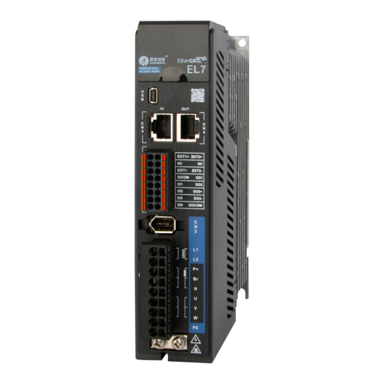
- Page 15 User manual of EL7-PN***F AC Servo 1.4 Servo Drive Ports and Connectors Front view of EL7-PN Series AC Servo Drive...
- Page 16 L1C、L2C :Control circuit power supply(Single phase 220VAC) L1、L2、L3:Main power supply 220VAC/380VAC : Note EL7-PN series supports 1P/3P 220/380VAC main Main power supply power supply 220/380VAC P+: Positive terminal of servo drive internal DC bus P+,B1,B2: Connect B1 and B2 to use internal regenerative ;...
- Page 17 User manual of EL7-PN***F AC Servo 1.5 Motor ports and connectors Motors with aviation connectors ② Power connector ① Encoder connector ③ Motor flange ④Installation screw holes ⑤ Motor shaft Motors with direct connectors ① Encoder Power connector ② connector Motor flange ③...
- Page 18 User manual of EL7-PN***F AC Servo Chapter 2 Installation & Wiring 2.1 Servo Drive Installation 2.1.1 Servo drive installation environment Storage: -20-80℃ (Condensation free); Temperature Installation: 0-55℃ (Not frozen) Humidity Under 90%RH (Condensation free) Altitude Up to 1000m above sea level Vibration Less than 0.5G (4.9m/s2) 10-60Hz (non-continuous working) Atmospheric...
- Page 19 User manual of EL7-PN***F AC Servo 2.1.2 Servo drive dimension Dimension 1:EL7-PN400~1000F / EL7-PN750~1500FT 55mm×175mm×179mm Dimension 2:EL7-PN1500~2000F / EL7-PN2000~3000FT 80mm×175mm×179mm Dimension 3:EL7-PN4400~7500FT 89mm×230mm×250mm...
- Page 20 User manual of EL7-PN***F AC Servo Space requirement for installation In order to ensure efficient heat dissipation, please leave at least 10mm installation space in between drivers. If drivers need to be mounted compactly, please leave at least 1mm of installation space.
- Page 21 User manual of EL7-PN***F AC Servo 2.2 Servo Motor Installation 2.2.1 Installation conditions Installation conditions may affect the lifespan of a motor Please keep away from corrosive fluid and combustibles. If dusty working environment is unavoidable, please use motors with oil seal. ...
- Page 22 User manual of EL7-PN***F AC Servo Connectors Please to remove any conductive foreign objects from the connectors before installation The connectors are made of resin. May not withstand impact. Please hold the driver during transportation, not the cables. ...
- Page 23 User manual of EL7-PN***F AC Servo EL7-PN Wiring Diagram EL7-PN 220V series AC servo drive wiring connection Please use a circuit breaker for the main power supply to prevent damage to the product or machine. Please do not use a contactor in connection to servo motor as it may not withstand a sudden surge of operating voltage.
- Page 24 User manual of EL7-PN***F AC Servo EL7-PN 220VAC Electrical Wiring Diagram 1ph/3ph 220VAC Circuit breaker Line Filter Contactor Connect B1 and B2 to use internal ; regenerative resistor If an external , regenerative resistor is needed , connect it to P+ and B2 disconnect B1 and B2 DICOM...
- Page 25 User manual of EL7-PN***F AC Servo EL7-PN 380VAC Electrical Wiring Diagram 3ph 380VAC Circuit breaker Line Filter Contactor Connect B1 and B2 to use internal ; regenerative resistor If an external , regenerative resistor is needed , connect it to P+ and B2 disconnect B1 and B2 DICOM...
- Page 26 User manual of EL7-PN***F AC Servo 2.4 Servo Drive Ports Port Function I/O Signal Port Encoder port USB mini Port PROFINET P1 Communication Port; From master or previous device PROFINET P2 Communication Port; To next slave device Safe Torque Off (STO) Port Main Power Supply Motor Power Supply Output Port...
- Page 27 User manual of EL7-PN***F AC Servo 2.5 X1 Main power supply Functions Port Remarks Control circuit: ① Optional isolation transformer , Single phase 220VAC ② In case of serious interference, it is +10~-15%,50/60Hz recommended to connect a line filter to main power supply;...
- Page 28 User manual of EL7-PN***F AC Servo 2.5.1 Regenerative resistor selection and connections The use of regenerative resistor When the motor opposes the direction of rotation as in deceleration or vertical axis escalation, part of the regenerative energy will be delivered back to the driver. This energy will first be stored in internal capacitors of the driver.
- Page 29 User manual of EL7-PN***F AC Servo If driver overvoltage alarm (Er120) occurs, please use an external regenerative resistor with lower resistance or connect another resistor in parallel. Please take following precautions before installing an external regenerative resistor. 1. Please set the correct resistance value in Pr0.16 and resistor power rating Pr0.17 for the external regenerative resistor.
- Page 30 User manual of EL7-PN***F AC Servo Theoretical selection of regenerative resistor Without external loading torque, the need for an external regenerative resistor can be determined as the flow chart below Start T is the time for velocity to reach Determine the max.
- Page 31 User manual of EL7-PN***F AC Servo V:Motor rotational velocity Rotational velocity :Deceleration time Motor Torque : Load torque Regenerative torque Steps Calculation Symbol Formula Servo system regenerative E1=(N+1)×J×V /182 energy = (π/60) V×T Depleted energy from loss of ×tD load system during If loss is not determined, please assume E acceleration /R)×tD...
- Page 32 User manual of EL7-PN***F AC Servo Calculation examples: Servo drive: EL7-PN750F, Servo Motor: When T = 2s, rotational velocity = ELM2H-0750LA80. 3000rpm, load inertia is 5 times of motor inertia. Rotor Inertia (× Max. regenerative energy EL7-PN Drivers Servo motor )...
- Page 33 User manual of EL7-PN***F AC Servo Connection of a regenerative resistor 2.5.2 Wire Gauge for Main Power Supply Wire diameter (mm /AWG) Driver L1 L2/R S T P+ BR U V W EL7-PN400F 0.81/AWG18 2.1/AWG14 1.3/AWG16 2.1/AWG14 EL7-PN750F 0.81/AWG18 2.1/AWG14 1.3/AWG16 2.1/AWG14 EL7-PN1000F...
- Page 34 User manual of EL7-PN***F AC Servo 2.5.3 Holding brake wiring diagram Holding brake is activated when servo drive is not powered on to prevent axis from moving due to gravitational pull or other external forces by locking the motor in place. Usually used on axis mounted vertically to the ground so that the load would not drop under gravitational force when the driver is powered off or when alarm occurs.
- Page 35 User manual of EL7-PN***F AC Servo 2.5.4 Cable selection for motor with holding brake Aviation connector(Frame size 80 or below)CABLE-RZSH*M*-113-TS Winding cable with holding brake Motor side Driver side Motor cable pin Pins Motor Color Driver Blue Black Yellow- green Black Motor side Direct connector CABLE-RZH*M*-114-TS Winding cable with holding brake...
- Page 36 User manual of EL7-PN***F AC Servo Mechanical noise might exist when motor with holding brake is in operation but it doesn’t affect the functionality of the motor. When the holding brake circuit is closed (holding brake deactivated), there might be magnetic flux leakage.
- Page 37 Example of motor power cable connection using an AMP electrical connector Motor winding power cable Wire length available: 1.5m, 3m and 5m Connectors type available: Aviation connectors, direct connectors (recommended) Please contact Leadshine sales team or any Leadshine certified local retailers for any customized needs.
- Page 38 User manual of EL7-PN***F AC Servo *M*: Length of the cable Aviation connector(Frame size 130) CABLE-RZ*H(V1.1/V2.0) Motor side Driver side Pins Motor cable pin Motor Color Driver Green Black Yellow Motor side Direct connector(Frame size 80 or below)CABLE-RZH*M*-114-TS without holding brake Motor side Driver side...
- Page 39 User manual of EL7-PN***F AC Servo 2.7 CN1 I/O signals port CN1 port uses a 20-pin spring terminal block connector. Port Signal Description Remarks Common DI DICOM 1. Double-ended digital Digital input 1 input Digital input 2 2. Configurable input Digital input 3 signals Digital input 4...
- Page 40 User manual of EL7-PN***F AC Servo Pin terminals on motor side Motor side Driver side Frame 80 or Frame 130 (1394 6PIN) Frame 130 below (850w,1300w,1800w) Frame 1(Shielding) 1(Shielding) 1(Shielding) (3) (3) BAT+ (4) BAT- (2) Please ground both driver and motor PE terminals to avoid any servo alarms. ...
- Page 41 User manual of EL7-PN***F AC Servo 2.8.2 Motor encoder cable and connector selection Aviation connector(Frame size 130)CABLE-7BM*HZ(V3.0) Motor side Driver side Motor cable pin Motor Driver Signal Frame Shielded BAT+ BAT- Motor side Direct connector(Frame size 80 or below)CABLE-BMH*M*-114-TS Incremental encoder Motor side Driver side Motor cable pin...
- Page 42 User manual of EL7-PN***F AC Servo Direct connector(Frame size 80 or below)CABLE-BMAH*M*-124-TS Absolute encoder Motor side Driver side Motor cable pin Motor Driver Signal Frame Shielded BAT+ BAT- Motor side 2.9 CN3/CN4 PROFINET Communication Port CN3(P1) connects from master controller or from previous slave device and CN4(P2) connects to the next slave device.
- Page 43 User manual of EL7-PN***F AC Servo 2.10 CN6 Safe Torque Off (STO) Port Port Signal Description Remarks 24v power supply Connect to SF1 and SF2 when not in use. Do not use Reference ground to supply power. Control signal 1 SF1+ positive input Control signal 1...
- Page 44 STO malfunction. 2.11 USB mini Tuning Port EL7-PN series servo drives can be connected to a PC using the USB mini communication port for data monitoring and parameters setting on Motion Studio. Please connect to main power supply before tuning the driver.
- Page 45 User manual of EL7-PN***F AC Servo 2.12 I/O signals 2.12.1 Common input circuit The internal circuit of common input is a bidirectional optocoupler which supports common anode and common cathode configurations. There are 2 types of outputs from master device: Relay output and Open Collector output as shown below.
- Page 46 User manual of EL7-PN***F AC Servo 2.12.2 Common output circuit There are 3 common outputs: all 3 outputs are double-ended which can be connected to an independent power source. Double-ended DO3+ & DO3- INP+ DO3+ 12~24Vdc INP- DO3- Driver interior ...
- Page 47 User manual of EL7-PN***F AC Servo Related parameters Label Input selection DI1 Mode Range 0x0~0xFF Unit — Default 5000 Pr4.00 Activation Immediate Label Input selection DI2 Mode Range 0x0~0xFF Unit — Default 5001 Pr4.01 Activation Immediate Label Input selection DI3 Mode Range 0x0~0xFF...
- Page 48 User manual of EL7-PN***F AC Servo 2.12.4 DO signal function configuration Factory default Signal Parameter Default function Polarity Status value Pr4.10 Alarm(ALM) 0x01 Servo Ready(SRDY) Pr4.11 0x02 Positioning 10/12 Pr4.12 0x04 completed(INP) **NO: Normally Open Normally Open(NO) and Normally Close(NC) Polarity = NO, Signal input disconnected, Status = OFF Signal input connected, Status = ON...
- Page 49 User manual of EL7-PN***F AC Servo Homing done HOME-OK Please don’t set any other than the outputs listed in the table above. · Normally open:Active low · Normally close:Active high · Front panel is of hexadecimal system. · Pr4.10 – Pr4.12 corresponds to DO1 – DO3. If all parameters are set to 0, master device controls the outputs, object dictionary 0x60FE sub-index 01 bit16-18 corresponds to DO1- DO3.
- Page 50 User manual of EL7-PN***F AC Servo 2.13.1 Grounding connection and other anti-interference wiring connections Contactor Servo Drive Line Filter Encoder 3.5mm or above 2.0mm above 3.5mm or above Ground Grounded Servo motor frame should be grounded. Please connect the PE terminal of servo motor and servo drive and ground them together to reduce interference.
- Page 51 User manual of EL7-PN***F AC Servo Ground wires inside an electrical cabinet Contactor Servo drive Line Filter Servo drive Ground Shield grounding...
- Page 52 User manual of EL7-PN***F AC Servo Chapter 3 Parameter 3.1 Parameter List Panel Display as follows: Parameter Valid mode Description F: Valid in all modes 3.1.1 Servo drive parameter Panel Label Class Activation Valid Mode display Model-following 1000 PR_000 Immediate bandwidth...
- Page 53 User manual of EL7-PN***F AC Servo Panel Label Class Activation Valid Mode display of Velocity Loop velocity detection filter 2003 PR_103 Immediate Torque Filter Time 2004 PR_104 Immediate Constant Position Loop Gain 2005 PR_105 Immediate velocity loop gain 2006 PR_106 Immediate Integral Time Constant of Velocity Loop...
- Page 54 User manual of EL7-PN***F AC Servo Panel Label Class Activation Valid Mode display anti-resonant 3033 PR_233 Immediate frequency anti-resonant Q value 3035 PR_234 Immediate resonant frequency 3035 PR_235 Immediate resonant Q value 3036 PR_236 Immediate anti-resonant 3037 PR_237 Immediate frequency anti-resonant Q value 3038 PR_238...
- Page 55 User manual of EL7-PN***F AC Servo Panel Label Class Activation Valid Mode display brake release Holding brake activation 5039 PR_439 Immediate velocity Emergency stop function 5043 PR_443 Immediate Holding brake duty cycle 5051 PR_451 Immediate Driver prohibition input 6004 PR_504 Immediate settings Servo-off mode...
- Page 56 User manual of EL7-PN***F AC Servo Panel Label Class Activation Valid Mode display Velocity observer 7029 PR_629 Immediate bandwidth Frame error window time 7034 PR_634 Immediate Frame error window 7035 PR_635 Immediate Absolute value rotation mode denominator 7054 PR_654 After restart setting Rotor blocked torque limit 7056...
- Page 57 User manual of EL7-PN***F AC Servo Panel Label Class Activation Valid Mode display 61003/ Immediate Default gateway Pr_A48 11048 61002/ Immediate MAC address low bit Pr_A49 11049 61002/ Immediate MAC address mid bit Pr_A50 11050 61002/ Immediate MAC address high bit Pr_A51 11051 922/11...
- Page 58 User manual of EL7-PN***F AC Servo Panel Label Class Activation Valid Mode display 1202 Immediate EPOS max. acceleration Pr_B25 1202 Immediate EPOS max. deceleration Pr_B26 EPOS software negative 1202 Immediate position limit Pr_B27 EPOS software positive 1202 Immediate position limit Pr_B28 1202 Immediate...
- Page 59 User manual of EL7-PN***F AC Servo Panel Label Class Activation Valid Mode display 1205 Immediate Function expansion Pr_B50 PR_B5 Ramp stoppage 1205 Immediate deceleration time PR_B5 Quick stop deceleration 1205 Immediate time...
- Page 60 User manual of EL7-PN***F AC Servo 3.2 Parameter Function 3.2.1【Class 0】Basic Settings Label Model-following bandwidth Valid Mode Pr0.00 Range 0~5000 Unit 0.1Hz Default 1000 Model-following bandwidth, also known as model-following control (MFC), is used to control the position loop to improve the responsiveness to commands, speed up positioning time and reduce following error.
- Page 61 User manual of EL7-PN***F AC Servo recommended for load mounted vertical to ground, or please compensate for the load using Pr6.07 Used to select the load type, choose according to load-inertia ratio and mechanical structure. This mode prioritizes system responsiveness. Use this mode when there is a relatively rigid structure with low 0: Rigid load inertia.
- Page 62 User manual of EL7-PN***F AC Servo Label Inertia ratio Mode Pr0.04 0~1000 Range Unit Default 1004 Pr0.04=( load inertia/motor rotational inertia)×100% Set inertia ratio according to actual load inertia. When both are uniform, actual motor velocity loop responsiveness and gain settings will be consistent. If inertia ratio is greater than actual value, velocity loop gain settings will be higher and vice versa.
- Page 63 User manual of EL7-PN***F AC Servo Command pulse counts Label Mode per revolution Pr0.08 0~838860 Range Unit Default 1008 Activation After restart To set command pulse counts per motor revolution. Encoder pulse output per Label Mode revolution Pr0.11 Range 0~65535 Unit Default 2500...
- Page 64 User manual of EL7-PN***F AC Servo 0~3276 Range Unit Default 1015 Activation Immediate 0: Incremental mode: Used as an incremental encoder. Doesn’t retain position data on power off. Unlimited travel distance. 1: Multiturn linear mode: Used as a multiturn absolute encoder. Retrain position data on power off. For applications with fixed travel distance and no multiturn data overflow.
- Page 65 User manual of EL7-PN***F AC Servo Synchronous Label Mode compensation time 2 Pr0.26 Range 1~2000 Unit 0.1us Default 1026 Activation After restart Synchronous dithering compensation range. Used for master device with poor synchronization. 3.2.2【Class 1】Gain Adjustments Label position loop gain Mode Range 0~30000...
- Page 66 User manual of EL7-PN***F AC Servo Label velocity detection filter Mode 0~1000 Range Unit — Default 2003 Pr1.03 Activation Immediate This filter is a low pass filter. It blocks high frequencies which cause system instability from velocity feedback data. The higher the set value, lower frequencies will be blocked and velocity responsiveness will also be lowered.
- Page 67 User manual of EL7-PN***F AC Servo Label Position Loop Gain Mode Range 0~30000 Unit 0.1/s Default 2005 Pr1.05 Activation Immediate Label velocity loop gain Mode Range 1~32767 Unit 0.1Hz Default 2006 Pr1.06 Activation Immediate Integral Time Label Constant of Velocity Mode Loop Pr1.07...
- Page 68 User manual of EL7-PN***F AC Servo Velocity feed forward Label Mode gain Pr1.10 Range 0~1000 Unit 0.10% Default 2010 Activation Immediate Velocity control command according to internal position command processing or through PN communication multiplied by Pr1.10 and add on to velocity command after position command processing Torque Velocity...
- Page 69 User manual of EL7-PN***F AC Servo Torque feed forward Label Mode gain 0~100 Pr1.12 Range Unit 0.1% Default 2012 Activation Immediate Before using torque feed forward, please set correct inertia ratio Pr0.04. By increasing torque feed forward gain, position deviation on constant acceleration/deceleration can be reduced to close to 0.
- Page 70 User manual of EL7-PN***F AC Servo Position control gain Label Mode switching mode Pr1.15 Range 0~11 Unit — Default 2015 Activation Immediate Condition Gain switching condition Value gain fixed Fixed on using 1 gain(Pr1.00-Pr1.04) gain fixed Fixed on using 2 gain (Pr1.05-Pr1.09) Reserved Switch to 2...
- Page 71 User manual of EL7-PN***F AC Servo Valid for position control. Switch to 2 gain when position deviation absolute value larger than (level + hysteresis)[pulse] Switch to 1 gain when position deviation absolute value smaller than (level-hysteresis)[pulse] Large position deviation Velocity Level Hysteresis Position...
- Page 72 User manual of EL7-PN***F AC Servo Hysteresis Level Velocity Feedback Valid for position control. gain if position command ≠ 0 Switch to 2 Switch to 1 gain if positional command = 0 throughout the duration of delay time and absolute value of actual velocity remains smaller than (level - hysteresis) (r/min) Pending position command...
- Page 73 User manual of EL7-PN***F AC Servo Hysteresis at position Label Mode control switching Mode Pr1.18 Range 0~20000 Unit Default 2118h dependent Activation Immediate To eliminate instability of gain switching. Used in combination with Pr1.17 using the same unit. If level< hysteresis, drive will set internally hysteresis = level. Position gain switching Label Mode...
- Page 74 User manual of EL7-PN***F AC Servo Label Mode Unique Registry 1 Range 0~0xFFFF Unit Default 2038 Pr1.38 Activation Immediate 3.2.3【Class 2】Vibration Suppression Adaptive filtering mode Label Mode settings Pr2.00 Range Unit Default 3000 Activation Immediate Set value Explanation Adaptive filter: invalid Parameters related to 3 and 4 notch filter...
- Page 75 User manual of EL7-PN***F AC Servo Label notch depth selection Mode Range 0~99 Unit Default 3003 Pr2.03 Activation Immediate Set notch depth for 1 resonant notch filter. Under normal circumstances, please use factory default settings. If resonance is under control, in combination with Pr2.01 and Pr2.02, Pr2.03 can be reduced to improve current loop responsiveness which allows higher mechanical stiffness settings.
- Page 76 User manual of EL7-PN***F AC Servo notch bandwidth Label Mode selection Pr2.08 Range 0~20 Unit Default 3008 Activation Immediate Set notch bandwidth for 3 resonant notch filter. Under normal circumstances, please use factory default settings. Label notch depth selection Mode Range 0~99 Unit...
- Page 77 User manual of EL7-PN***F AC Servo Position command Label Mode smoothing filter Pr2.22 Range 0~32767 Unit 0.1ms Default 3022 Activation Stop axis To set time constant of 1 time delay filter of position command. To set time constant of 1 time delay filter, according to target velocity Vc square wave command as show below.
- Page 78 User manual of EL7-PN***F AC Servo undershoot. To smoothen command signal, reduces impact to machines and eliminate vibration. If Pr2.23 is set too high, overall time will be lengthened. **Please wait for command to stop and after filter idle time to modify Pr2.23. Filter switching time = (Pr2.23 set value x 0.1ms + 0.25ms) Label Mode...
- Page 79 User manual of EL7-PN***F AC Servo Label Mode resonant frequency Range 50~4000 Unit Default 4000 2035 Pr2.35 Activation Immediate To set zero-valued eigenfrequency of 6 resonant notch filter. Pr2.35 corresponds to machine- specific resonant frequency. Notch filter deactivated if Pr2.31 is set to any value. Label resonant Q value Mode...
- Page 80 User manual of EL7-PN***F AC Servo 5.2.4【Class 3】Velocity Control Label Acceleration time settings Mode Range 0~10000 Unit Default 4012 Pr3.12 (1000RPM) Activation Immediate Label Deceleration time settings Mode Range 0~10000 Unit Default 4013 Pr3.13 (1000RPM) Activation Immediate Set max acceleration/deceleration for velocity command. If target velocity = x [rpm], max acceleration = a [unit: rpm/ms], acceleration time = t [ms] With added Pr3.12 = 1000/a...
- Page 81 User manual of EL7-PN***F AC Servo Label Zero speed clamp level Mode Range 10~2000 Unit Default 4016 Pr3.16 Activation Immediate Velocity command is forced to 0 when actual velocity is lower than Pr3.16 and after static time set in Pr3.23 Zero speed clamp static Label Mode...
- Page 82 User manual of EL7-PN***F AC Servo Activation Immediate Digital input DI allocation using hexadecimal system Set value Input Symbol Normally Normally open close Invalid — Positive limit switch Negative limit switch Clear alarm A-CLR Forced alarm E-STOP Home switch HOME-SWITCH ·...
- Page 83 User manual of EL7-PN***F AC Servo Please don’t set any other than the outputs listed in the table above. · Normally open:Active low · Normally close:Active high · Front panel is of hexadecimal system. · Pr4.10 – Pr4.12 corresponds to DO1 – DO3. Label Analog input 1 zero drift Mode...
- Page 84 User manual of EL7-PN***F AC Servo Positioning complete Label Mode range 0~1000 Command Pr4.31 Range Unit Default 5031 unit Activation Immediate To set position deviation range of INP1 positioning completed output signal. Positioning complete Label Mode output setting Pr4.32 Range Unit Default 5032...
- Page 85 User manual of EL7-PN***F AC Servo Label Zero speed Mode 1~200 Range Unit Default 5034 Pr4.34 Activation Immediate To set threshold value for zero speed clamp detection. Zero speed clamp detection (ZSP) output signal valid when motor speed goes under the value set in Pr4.34 Disregard the direction of rotation, valid for both directions.
- Page 86 User manual of EL7-PN***F AC Servo Label Velocity reached Mode Range 10~2000 Unit Default 1000 2436h Pr4.36 Activation Immediate When motor velocity > Pr4.36, AT-speed output signal is valid. Detection using 10RPM hysteresis. Label Mode Motor power-off delay time Range 0~3000 Unit Default...
- Page 87 User manual of EL7-PN***F AC Servo SRV_ON Brake released (BRK_ON) Brake BRK_OFF Motor Power Released Actual holding Braked Braked brake status Motor Velocity *1: Delay time set in Pr4.38 *2: Delay time from the moment BRK_OFF signal is given until actual holding brake is released or BRK_ON signal is given until actual holding brake is activated.
- Page 88 User manual of EL7-PN***F AC Servo Label Emergency stop function Mode Range Unit Default 5043 Pr4.43 Activation Immediate 0:Emergency stop is valid, servo driver will be forced to STOP and alarm occurs. 1:Emergency stop is invalid, servo driver will not be forced to STOP. Label Holding brake duty cycle Mode...
- Page 89 User manual of EL7-PN***F AC Servo Servo-off Label Mode alarm mode Pr5.10 Range Unit Default 6010 Activation After restart To set servo driver disable mode and status if alarm is triggered. Alarm type 2: Explanation Set value Mode Status Servo braking Dynamic braking Free stopping Dynamic braking...
- Page 90 User manual of EL7-PN***F AC Servo Range 0~10000 Unit Default 6013 Activation Immediate If motor speed exceeds Pr5.13, Er1A0 might occur. When Pr5.13 = 0, overspeed level = max. motor speed x 1.2 Label Mode I/O digital filter Range 0~255 Unit Default 6015...
- Page 91 User manual of EL7-PN***F AC Servo Range 0~35 Unit Default 6028 — Activation After restart To set content display on front panel of the servo driver at servo driver power on. Content Content Content value value value No. of encoder Position command communication Overload rate...
- Page 92 User manual of EL7-PN***F AC Servo Activation Immediate To set torque limit during torque initialization Between max. torque 6072 and Pr5.22, actual torque limit will take smaller value. Label D41 set value Mode Range 0x0~0xFFFFF Unit Default 0X30C 6040 Pr5.40 Activation Immediate Set object word monitored by D41, index (left 4 bits) + sub-index (right 1 bit), if monitoring...
- Page 93 User manual of EL7-PN***F AC Servo Label Position 3 gain valid time Mode Range 0~10000 Unit 0.1ms Default 7005 Pr6.05 Activation Immediate To set time for 3 gain to be valid When not in use, set Pr6.05=0, Pr6.06=100 Position gain scale Label Mode...
- Page 94 User manual of EL7-PN***F AC Servo Label Negative direction torque Mode compensation value Range Unit Default -100~100 7009 Pr6.09 Activation Immediate To reduce the effect of mechanical friction in the movement(s) of the axis. Compensation values can be set according to needs for both rotational directions. Applications: 1.
- Page 95 User manual of EL7-PN***F AC Servo Label Trial run distance Mode Range 0~1200 Unit 0.1rev Default 7020 Pr6.20 Activation Immediate JOG (Position control) : Distance travel of each motion Label Trial run waiting time Mode Range 0~30000 Unit Default 7021 Pr6.21 Activation Immediate...
- Page 96 User manual of EL7-PN***F AC Servo Label Frame error window Mode Range 0~32767 Unit Default 7035 Pr6.35 Activation Immediate To set data frame error detection window Absolute value rotation Label Mode mode denominator setting Pr6.54 Range 0~32766 Unit Default 7054 Activation After restart To set denominator of absolute encoder in rotational mode.
- Page 97 User manual of EL7-PN***F AC Servo Label Z signal holding time Mode Range 0~100 Unit Default 7061 Pr6.61 Activation Immediate To set the holding time for Z signal to maintain active high Application: 1. Z signal for homing process 2. Z-phase frequency output pulse width. Unit = 0.1ms; Please set Pr6.61≥0.2ms if used for 2 applications as above Absolute multiturn data Label...
- Page 98 User manual of EL7-PN***F AC Servo Label Encoder Mode As per Range 0x0~0x200 Unit Default Property Pr7.16 encoder Activation After restart Data length 16 bit Set value Description 17-bit encoder 23-bit encoder 3.2.9 【Class A】PN communication Label Heartbeat alarm threshold Mode PrA.00 Range...
- Page 99 User manual of EL7-PN***F AC Servo Label Save parameters Mode PrA.16 Range 2147482648~21 Unit Default 977/11016 47482647 Save all driver’s parameters to ROM. Only configurable parameters are saved. Description Deactivated Non-volatile saving. Load upon power on Label Sensor settings Mode PrA.22 Range 0 ~ 4294967295...
- Page 100 User manual of EL7-PN***F AC Servo Label Sensor multiturn turn count Mode PrA.27 Range 0 ~ 4294967295 Unit Default 979/11027 Description Incremental encoder (Unable to read absolute value from G2_XIST2) Single turn absolute value Multiturn absolute value Label User defined receive data value Mode PrA.38 Range...
- Page 101 User manual of EL7-PN***F AC Servo Label Subnet mask Mode PrA.47 Range 0 ~ 4294967295 Unit Default 61001/11047 To set slave subnet mask Label Default gateway Mode PrA.48 Range 0 ~ 4294967295 Unit Default 61003/11048 To set slave gateway Label MAC address low bit Mode PrA.49...
- Page 102 User manual of EL7-PN***F AC Servo Label Max synchronization cycle time Mode PrB.02 μs Range 0 ~4294967295 Unit Default 100000 12002 Maximum value of synchronization cycle time Label Planner state machine Mode PrB.04 Range 0 ~4294967295 Unit Default 12004 Internal planner state machine Label Internal motion state machine Mode...
- Page 103 User manual of EL7-PN***F AC Servo Label Max. homing distance Mode PrB.14 Range 0 ~2147483647 Unit Default 12014 Max. distance in a single homing process. Label Planner command position Mode PrB.15 -2147483647 Range Unit Default 12015 ~2147483647 Internal planner command position value Label Planner command velocity Mode...
- Page 104 User manual of EL7-PN***F AC Servo EPOS software negative position Label Mode limit PrB.27 -2147483647 Range Unit Default 12027 ~2147483647 Basic Positioner EPOS software negative position limit set value EPOS software positive position Label Mode limit PrB.28 -2147483647 Range Unit Default 12028 ~2147483647...
- Page 105 User manual of EL7-PN***F AC Servo Label EPOS JOG2 distance Mode PrB.36 Range 0 ~2147483647 Unit Default 1000 12036 Set travel distance for EPOS JOG2 Label EPOS Homing mode Mode PrB.37 Range -6~37 Unit Default 12037 Homing mode under EPOS, same as CiA402 Home Mode Label EPOS home position Mode...
- Page 106 User manual of EL7-PN***F AC Servo Label MDI ending velocity Mode PrB.45 1000LU/ Range 1~40000000 Unit Default 12045 Ending velocity under MDI mode Label MDI acceleration rate Mode PrB.46 0x4000= Range 0.1~100 Unit Default 12046 100% Acceleration rate under MDI mode Label MDI deceleration rate Mode...
- Page 107 User manual of EL7-PN***F AC Servo Chapter 4 Servo Drive Operation 4.1 Start with Driver Operation 4.1.1 Checklist before operation Description Power supply The voltage of main and control circuit power supply is within rated values. Power supply polarity is rightly connected. Wiring Power supply input is rightly connected.
- Page 108 User manual of EL7-PN***F AC Servo 4.1.2 Trial Run Servo drive must be disabled before performing trial run. For safety precautions, please JOG under minimal velocity. Related Parameters Parameters Label Set value Unit Pr0.01 Control mode settings Pr6.04 JOG trial run command velocity User defined r/min Pr6.25...
- Page 109 Magnetic sensors might be affected when the holding brake is on. Please be aware. Holding brake wiring EL7-PN series AC Servo Drives supports direct drive holding brakes. Please connect motor holding brake to BRK+ and BRK- on CN1 to control holding brake activation. External relay is not required.
- Page 110 User manual of EL7-PN***F AC Servo 4.1.5 Servo stop Servo stopping are of 3 different methods: Servo braking method, free stopping method, dynamic braking method. Stopping method Description Details Servo braking Servo driver delivers braking torque in Quick stopping but mechanical opposite direction impact might exist Free stopping...
- Page 111 User manual of EL7-PN***F AC Servo Motor stopping(Servo disabled)- Sequence Diagram Servo braking method. Status after stopping: Dynamic braking Input coupler Servo enabled Input coupler Input coupler SRV-ON Dynamic Activated Deactivated Activated brake Enabled Disabled Disabled Servo status SRV-ST Power OFF Power ON Power OFF Motor power...
- Page 112 User manual of EL7-PN***F AC Servo Servo stopping method. Status after stopping: free moving Input coupler Servo enabled Input coupler Input coupler SRV-ON Dynamic Activated Deactivated brake Enabled Disabled Disabled Servo status SRV-ST Power ON Motor power Power OFF Power OFF Brake ON Brake ON Holding brake status...
- Page 113 User manual of EL7-PN***F AC Servo Free stopping method. Status after stopping: Free moving Input coupler Servo enabled Input coupler Input coupler SRV-ON Dynamic Activated Deactivated brake Enabled Disabled Servo status Disabled SRV-ST Power OFF Power ON Power OFF Motor power Holding brake Brake ON Brake ON...
- Page 114 User manual of EL7-PN***F AC Servo Dynamic braking method. Status after stopping: Free moving Servo enabled Input coupler Input coupler Input coupler SRV-ON Activated Dynamic Activated Deactivated Deactivated brake Enabled Disabled Disabled Servo status SRV-ST Power OFF Power ON Power OFF Motor power Brake ON Holding brake status...
- Page 115 User manual of EL7-PN***F AC Servo Stopping when alarm occurs – Sequence Diagram Servo braking method. Status after stopping: Dynamic braking Error Error Normal occurrence Servo status Enabled Disabled SRV-ST Activated Dynamic brake Deactivated Motor power Power ON Power OFF Servo ready Ready Not Ready...
- Page 116 User manual of EL7-PN***F AC Servo Free stopping method. Status after stopping: Dynamic braking Error Alarm Normal occurrence Servo status Enabled SRV-ST Disabled Activated Dynamic Deactivated brake Motor power Power Power OFF Servo Ready S-RDY Ready Not Ready Servo Alarm No Alarm Alarm Holding brake...
- Page 117 User manual of EL7-PN***F AC Servo Dynamic braking method. Status after stopping: Dynamic braking Error Alarm Normal occurrence Servo status SRV-ST Enabled Disabled Activated Dynamic Deactivated brake Motor power Power ON Power OFF Status ready S-RDY Ready Not Ready Servo Alarm No Alarm Alarm Holding brake...
- Page 118 User manual of EL7-PN***F AC Servo Servo braking method. Status after stopping: Free moving Error Alarm Normal occurrence Servo status SRV-ST Enabled Disabled Dynamic Deactivated brake Motor power Power Power OFF Servo ready S-RDY Ready Not Ready Servo alarm No Alarm Alarm Holding brake Brake OFF...
- Page 119 User manual of EL7-PN***F AC Servo Free stopping method. Status after stopping: Free moving Error Alarm Normal occurrence Servo status Enabled Disabled SRV-ST Dynamic Deactivated brake Motor power Power ON Power OFF Servo ready Ready Not Ready S-RDY Servo alarm No Alarm Alarm Holding brake...
- Page 120 User manual of EL7-PN***F AC Servo Dynamic braking. Status after stopping: Free moving Error Error Normal occurrence Servo status Enabled Disabled SRV-ST Activated Dynamic Deactivated Deactivated brake Motor power Power ON Power OFF Servo Ready S-RDY Ready Not Ready Servo Alarm No Alarm Alarm Holding brake...
- Page 121 User manual of EL7-PN***F AC Servo Alarm clearing - Sequence diagram Input coupler ON Alarm clearing Input coupler OFF A-CLR Dynamic brake Activated Deactivated Servo Disabled Enabled status SRV-ST Power ON Motor power Power OFF Brake OFF External brake Brake ON deactivation BRK-OFF Servo...
- Page 122 User manual of EL7-PN***F AC Servo 4.1.6 Electronic gear ratio When loaded axis moved for 1 command unit, it corresponds to motor encoder unit which is converted in more comprehensible physical units such as μm. The use of electronic gear ratio is to turn the movement in physical units to required pulse count equivalency.
- Page 123 User manual of EL7-PN***F AC Servo 4.2 Front Panel Servo Driver front panel consists of 5 push buttons and a 8-segments display. Can be used for displaying of status, alarms, functions, parameters setting and auxiliary functions. Front panel Buttons and functions Label Symbol Function...
- Page 124 User manual of EL7-PN***F AC Servo 4.2.1 Panel Display and Operation Power ON rEAdy Display “ ” for 1s d 0 0 u E Data monitoring mode d 3 4 S t Initialization display Display data values (EtherCAT not connected) d 4 2 o d Parameters setting mode Modify...
- Page 125 User manual of EL7-PN***F AC Servo 4.2.2 Front Panel Locking To prevent any misuse of the front panel, it can be locked. Limitations when locked are as shown below. Mode Limitation Data monitoring Not limited Parameters setting Parameters can only be read, not modified.
- Page 126 User manual of EL7-PN***F AC Servo d12Er d12Er Error cause and record “Er xxx” d13rn d13rn Warning “xxx” d14r9 d14r9 Regeneration load factor “xxx” d15oL d15oL Overload factor “xxx” d16Jr d16Jr Inertia ratio “xxx” d17Ch d17ch Motor not running cause “CP xxx”...
- Page 127 User manual of EL7-PN***F AC Servo Description of data monitoring function When using the front panel to monitor data, data is divided in low/high bit and positive/negative. Data is differentiated as below. . 2 . 6 0 8 8 5 High bit:1 and 2 values on the right has two decimal points...
- Page 128 User manual of EL7-PN***F AC Servo 2. d01SP Motor velocity,d02CS Position control command velocity,d03CU Velocity control command velocity d01SP r 4 0 0 Motor actual velocity(r/min) Command velocity under position d02CS 4 0 0 control(r/min) Command velocity under velocity d03CU 4 0 0 control(r/min)...
- Page 129 User manual of EL7-PN***F AC Servo 5. d07 Maximum torque during motion Maximum torque during motion 6. d08FP Internal command pulse sum d 0 8 F P Internal command pulse sum (pulse) 7. d09Cn Control mode d 0 9 C n C t p o s ...EtherCAT mode 8.
- Page 130 User manual of EL7-PN***F AC Servo 9. d12Er Alarm cause and historical record d12Er Er15 0 1 bit:Sub code Er150 ……Current error 2 bit:Main code ……Historical record 1 01150 (Latest) 140E0 ……Historical record 14 (Oldest) Press▲▼to check error historical record up to 14 records. 10.
- Page 131 User manual of EL7-PN***F AC Servo 12、d17Ch Motor not running cause d17Ch Error code of motor not running “d17Ch” Motor No Running Cause - Codes & Descriptions Display Code Description Content cP 1 DC bus undervoltage Servo-ON input (SRV-ON) is not connected cP 2 No SRV-ON signal to COM-...
- Page 132 ◀ User manual of EL7-PN***F AC Servo 13、d21AE Single turn encoder data d22rE Multiturn encoder data Example: Single turn 10748 d21AE encoder data = 8410748 Press ◀ to switch Single turn encoder data – high bit Single turn encoder data – low bit between high/low bit For 23-bit encoder, single turn encoder data = 0~8388607.Each value corresponds to certain position in a single revolution of the rotor, clockwise motion as negative, counter clockwise motion as positive.
- Page 133 User manual of EL7-PN***F AC Servo 16. d28no Software version Servo driver software version d28no d 210 (DSP) ▲▼ Communication software F - 10 version ▲▼ P 400 Servo driver power rating 17. d31tE Accumulated operation time d31tE 1256 ◀ Accumulated operation time (hour) Press...
- Page 134 User manual of EL7-PN***F AC Servo Display setting at power on ■ Default setting for initialization display settings at power on is ,if any other display is required, please set on Pr5.28. Please refer to Pr5.28 for any display content required on the front panel during initialization Label LED initial status Mode...
- Page 135 User manual of EL7-PN***F AC Servo 4.2.4 Parameter saving using front panel D00UE Increase/decrease value using ▲ ▼, press S to select PR000 ◀ the parameters to be modified Select value using After modifying the selected parameter to desired values, press S to confirm and save the changes.
- Page 136 User manual of EL7-PN***F AC Servo 4.3 Auxiliary functions Parameters settings Pr 0.000 mode Auxiliary functions Operation to select Press ▼ ▲ V o g - Trial run Trial run Reset to factory Reset to factory In I - default default U n L - Front panel unlock...
- Page 137 User manual of EL7-PN***F AC Servo AF jog Trial run Please disable servo driver before performing any trial run. Please don’t modify gain related parameters during trial run to prevent any occurrence of mechanical vibrations. Press S to exit trial run.
- Page 138 User manual of EL7-PN***F AC Servo AF unL Front panel unlock Auxiliary Operation Front panel AF unL unL - Initialization unlock FinSh is displayed after press ▲ once. Front panel unlocked FinSh AF ACL Clear alarm Alarm can be cleared using this auxiliary function but before that, the error needs to be solved and driver needs to be restarted.
- Page 139 User manual of EL7-PN***F AC Servo AF Enc Motor angle correction Auxiliary functions Operation AF Enc Motor angle Enc - Initialization correction StArt) ▲ once to start correct(displays Press FinSh is displayed once completed. StArt Start correction FinSh Completed AF_GL Inertia measuring Please make sure to use suitable velocity and acceleration for the measuring process.
- Page 140 User manual of EL7-PN***F AC Servo AF rSt Software reset Software reset is used mainly on parameters modification that takes effect only after driver restart. Auxiliary functions Operation Software Initialization AF rSt rSt - reset Press ▲ to reset software LED displayed will be off for 3s and back to initialization page once completed.
- Page 141 User manual of EL7-PN***F AC Servo Chapter 5 Application Case 5.1 Gain Adjustment In order for servo driver to execute commands from master device without delay and to optimize machine performance, gain adjustment has to be done yet. Servo driver gain adjustment is done in combination with a few other parameters (Inertia ratio, Position loop gain, Velocity loop gain and Filters settings).
- Page 142 User manual of EL7-PN***F AC Servo Start Electronic gear ratio Inertia measuring Auto gain adjustment Requirement met? Manual gain adjustment Requirement met? Vibration suppression Steps Functions Explanation Online Motor moves with command from controller, servo driver will automatically calculate load-inertia ratio Inertia measuring Offline...
- Page 143 User manual of EL7-PN***F AC Servo Auto gain Auto gain Real time determining of mechanical load, gain value is set adjustment adjustment accordingly. Basic gain On top of auto gain adjustment, manually adjust related parameters so that machine can have better responsiveness and following Manual gain...
- Page 144 User manual of EL7-PN***F AC Servo Auxiliary function to determine inertia on front panel Auxiliary Function Operation Inertia A F_ G L G - - - - Initialization measuring Press ‘◀’ to start inertia measuring. SrUon will be Press ‘S’ to enter displayed.
- Page 145 User manual of EL7-PN***F AC Servo Inertia measuring using Motion Studio 1. Start Motion Studio and maneuver to inertia ratio identification page under performance tuning. Set trial run velocity Pr6.04 and acc-/deceleration time Pr6.25, click on ‘Upload’ to upload parameters to servo driver. 2.
- Page 146 User manual of EL7-PN***F AC Servo 6. Click on “Parameter List” to enter parameters management to check or modify Pr0.04. Then, click on “Save” to save parameters to driver. Please take note: 1. Trial run velocity and distance should be optimal to prevent any axis from bumping into objects. 2.
- Page 147 User manual of EL7-PN***F AC Servo 5.3 Auto gain adjustment This function will measure real time mechanical properties and set gain values in accordance to mechanical stiffness. Can be used in any control mode Conditions to implement Please refer to Pr0.02 for detailed explanations. Auto gain adjustment is Control mode different for each control mode.
- Page 148 User manual of EL7-PN***F AC Servo constant Pr1.03 velocity detection filter Pr1.04 torque filter Pr1.05 position loop gain Pr1.06 velocity loop gain Pr1.07 velocity integral time constant Pr1.08 velocity detection filter Pr1.09 torque filter If auto gain adjustment is valid, the parameters listed above can’t be manually modified. Only when Pr0.02 = 0x00 or 0x10, can the gain related parameters be modified manually.
- Page 149 User manual of EL7-PN***F AC Servo This mode prioritizes system responsiveness. Use this mode when there is a relatively rigid structure with low 0: Rigid load inertia. Typical application including directly structure connected high-precision gearbox, lead screw, gears, etc. For applications with higher load inertia (10 times or above), gain settings take into account both machine 1:High inertia stability and responsiveness.
- Page 150 User manual of EL7-PN***F AC Servo 5.4 Manual gain adjustment Due to limitation of load conditions, automatic gain adjustment might not achieve expected performance. Control can be improved through manual gain adjustment The servo system is made up of 3 control loops. From outer to inner: position loop, velocity loop, current loop as shown in the diagram below.
- Page 151 User manual of EL7-PN***F AC Servo Step Parameter Label Tuning method To eliminate velocity loop deviation Actual velocity Command Reduce Pr1.02 velocity Pr1.02 Velocity loop integral time Velocity loop integral time constant (ms) = 4000 / (2*π*Velocity loop gain(Hz)) constant Reduce Pr1.02 to reduce positioning time.
- Page 152 User manual of EL7-PN***F AC Servo If vibration occurs with increasing Pr1.01, please modify Pr1.04 to suppress vibration. If the parameters are set too high, it might cause current loop response to reduce. To suppress vibration at stop, increase Pr1.01 and decrease Pr1.04. Decrease Pr1.04 if motor vibrates too much at rest.
- Page 153 User manual of EL7-PN***F AC Servo gain (Pr1.00-Pr1.04) and 2 gain (Pr1.05-Pr1.09) switching can be realized through manual and positioning mode. Switching condition is set through Pr1.15. Gain switching is invalid under standard mode. Start Pr0.02 – Standard mode Set Pr0.02 Pr0.02 –...
- Page 154 User manual of EL7-PN***F AC Servo Related parameters on gain switching Parameter Label Remarks In position control, set Pr1.15=3、5、 Position control gain Pr1.15 6、9、10。 switching mode In velocity control, set Pr1.15=3、5、9 Please set Pr1.17≥Pr1.18 Pr1.17 Position control level switching If Pr1.17<Pr1.18, driver will set Pr1.17 Position control Pr1.18...
- Page 155 User manual of EL7-PN***F AC Servo Hysteresis Level Velocity Valid for position control. Switch to 2 gain when position deviation absolute value larger than (level + hysteresis)[pulse] Switch to 1 gain when position deviation absolute value smaller than (level-hysteresis)[pulse] Large position deviation Velocity Level...
- Page 156 User manual of EL7-PN***F AC Servo Switch to 1 Hysteresis Level gain when actual Velocity velocity Feedback absolute value remains smaller throughout the duration of delay time than (level-hysteresis)[r/min] Valid for position control. gain if position command ≠ 0 Switch to 2 Switch to 1 gain if positional command = 0 throughout the duration of delay time and absolute value of actual velocity...
- Page 157 User manual of EL7-PN***F AC Servo Set threshold value for gain switching to occur. Unit is mode dependent. Switching Unit condition Position Encoder pulse count Velocity Torque Please set level ≥ hysteresis Hysteresis at position Label Mode control switching Mode Pr1.18 Range 0~20000...
- Page 158 User manual of EL7-PN***F AC Servo 5.6 Feedforward gain In position control, velocity feedforward is calculated by comparing the velocity control command calculated internally and velocity command calculated from position feedback. Comparing to control only using feedbacks, this will reduce position deviation and increase responsiveness. Besides, by comparing the torque needed during motion from velocity control command in comparison with velocity feedback, torque feedback can be calculated to improve system responsiveness.
- Page 159 User manual of EL7-PN***F AC Servo Velocity feed forward Label Mode filter time constant Pr1.11 Range 0~6400 Unit 0.01ms Default 2011 Activation Immediate Set velocity feed forward low pass filter to eliminate high or abnormal frequencies in velocity feed forward command. Often used when position command with low resolution or high electronic gear ration to smoothen velocity feed forward.
- Page 160 User manual of EL7-PN***F AC Servo 0~640 Range Unit 0.01ms Default 2013 Activation Immediate Low pass filter to eliminate abnormal or high frequencies in torque feed forward command. Usually used when encoder has lower resolution or precision. Noise reduces if torque feed forward filter time constant is set higher but position deviation will increase at acceleration varied points.
- Page 161 User manual of EL7-PN***F AC Servo 5.7 Model following control Model following control is a type of closed loop control system. First, an ideal model is constructed and acts as a reference for actual model in a closed loop control. Model following control can be treated as a control mode with 2 flexibilities: Model reference can be used to improve command responsiveness and closed loop control used to increase responsiveness of the system towards interference.
- Page 162 User manual of EL7-PN***F AC Servo 5.8 Friction compensation function This function is to compensation for changes in load to reduce the effect of friction in motion. The compensation value is directional. Velocity command Pr6.08 Pr6.07 Time Pr6.09 Velocity command Motor off Motor on Motor off...
- Page 163 User manual of EL7-PN***F AC Servo Label Negative direction torque Mode compensation value Range Unit Default -100~100 7009 Pr6.09 Activation Immediate To reduce the effect of mechanical friction in the movement(s) of the axis. Compensation values can be set according to needs for both rotational directions. Applications: 1.
- Page 164 User manual of EL7-PN***F AC Servo 5.9.2 External brake deactivation output signal BRK-OFF Please refer to Pr4.15 to set up the I/O output function parameters. When enabled and timing conditions in Pr4.39 and Pr6.14 are fulfilled, the set I/O output will deliver ON signal. The relation between SRV-ON and Pr4.37/Pr4.38: SRV_ON BRK_OFF...
- Page 165 User manual of EL7-PN***F AC Servo SRV_ON Brake released (BRK_ON) Brake BRK_OFF Motor Power Released Actual holding Braked Braked brake status Motor Velocity *1: Delay time set in Pr4.38 *2: Delay time from the moment BRK_OFF signal is given until actual holding brake is released or BRK_ON signal is given until actual holding brake is activated.
- Page 166 User manual of EL7-PN***F AC Servo 5.9.3 Emergency stop function Emergency stop is used when an alarm occurs or a servo prohibition signal is received when servo driver is enabled. Set up Pr4.43 to enable the function Label Emergency stop function Mode Range Unit...
- Page 167 User manual of EL7-PN***F AC Servo If analytic result from mechanical properties analysis tool doesn’t show any obvious peak but vibration did occur, it might not be due to mechanical resonance, it may be that servo gain has reached its limit. This kind of vibration can’t be suppressed by using notch filter, only by reducing gain and torque command filter time.
- Page 168 User manual of EL7-PN***F AC Servo Label notch frequency Mode Range 50~4000 Unit Default 4000 3001 Pr2.01 Activatio Immediate Set center frequency of 1 torque command notch filter. Set Pr2.01 to 4000 to deactivate notch filter notch bandwidth Label Mode selection Pr2.02 Range...
- Page 169 User manual of EL7-PN***F AC Servo Label notch depth selection Mode Range 0~99 Unit Default 3006 Pr2.06 Activation Immediate Set notch depth for 1 resonant notch filter. When Pr2.06 value is higher, notch depth becomes shallow, phase lag reduces. Under normal circumstances, please use factory default settings.
- Page 170 User manual of EL7-PN***F AC Servo 5.11 End vibration suppression End vibration Direction Motor Moving body If the mechanical has an end that is long and heavy, it might cause end vibration at emergency stop and affect the positioning. Usually happens on long armed axis with loose end. The frequency is usually within 100Hz which is lower than mechanical resonant frequencies.
- Page 171 User manual of EL7-PN***F AC Servo The result of suppressing low frequency resonance End low frequency suppression End vibration is End vibration is 激光测试仪测 measured using laser measured using laser 试末端振动 measurement device measurement device Actual Actual velocity velocity Label damping frequency Mode Range...
- Page 172 User manual of EL7-PN***F AC Servo 5.12 Mechanical properties analysis To determine mechanical and set up notch filter parameters to suppress vibration caused by resonance. To avoid strong vibration, please first set lower excitation amplitude. However, if the set value is too low, data waveform will include some degree of distortion.
- Page 173 User manual of EL7-PN***F AC Servo 5.13 Multiturn absolute encoder Multiturn absolute encoder records the position and the revolution counts of the motor. When driver is powered-off, multiturn absolute encoder will backed up the data using battery and after powering on, the data will be used to calculated absolute mechanical position and there is no need for a mechanical homing process.
- Page 174 User manual of EL7-PN***F AC Servo Install battery Pr0.15=1 Home process Finishing Homing process, set Pr0.15=9 Read absolute position *Note:The newly installed encoder is not initialized and will alarm 2、Read absolute position When the rotor turns in clockwise direction, the revolution count will be negative; turns in counter clockwise direction, the count will be positive.
- Page 175 User manual of EL7-PN***F AC Servo Multiturn rotational mode For absolute encoder, multiturn rotational mode (Pr0.15 = 2, Pr6.63 set to multiturn upper limit) is added on top of incremental mode and multiturn linear mode. Actual feedback multiturn data is always between 0 –...
- Page 176 User manual of EL7-PN***F AC Servo Motor Load Position during power-on Encoder position Actual position When electronic gear ratio = 1:1, 607Ch = 10000: Motor Load Position during power-on Encoder position Actual position 10000 -1)+10000 3、Clear multiturn position Before clearing multiturn position, axis needs to be homed. After clearing multiturn position, revolution count = 0 but absolute position remains unchanged and Err153 alarm will be cleared.
- Page 177 User manual of EL7-PN***F AC Servo Single turn Position Position during power-on Range of motion If power is turned off at position as shown below and power on when motor reaches the position below. Motor range of motion changes as shown below. Moved after power- Single Turn Position...
- Page 178 User manual of EL7-PN***F AC Servo (2)If battery voltage is lower than 3.2v. Replace battery and restart the motor. (3)If battery voltage is lower than 2.5v or battery power was cut off. Replacing the battery won’t clear the alarm. Axis needs to be homed and multiturn data needs to be cleared. 4、Alarm processing flow chart Err153 Absolute...
- Page 179 I/O devices or switch to support it. 6.1 Supported PROFINET Telegram EL7-PN series servo drives support application classes AC1, AC3 and AC4. Standard telegrams and Siemens telegrams are supported under velocity control mode and positioning control mode. Process data received is receive word; process data sent is send word.
- Page 180 User manual of EL7-PN***F AC Servo Telegram Application class AC1,4 AC1,4 PZD1 STW1 ZSW1 PZD2 NSOLL_B NIST_B PZD3 PZD4 STW2 ZSW2 PZD5 MOMRED MELDW PZD6 G1_STW G1_ZSW PZD7 G1_XIST1 PZD8 PZD9 G1_XIST2 PZD10 Telegram Application class PZD1 STW1 ZSW1 PZD2 NSOLL_B NIST_B PZD3...
- Page 181 User manual of EL7-PN***F AC Servo 6.2 I/O data signal Send/Receive Data Signal Label Scaling word type STW1 Control word 1 Receive STW2 Control word 2 Receive ZSW1 Status word 1 Send ZSW2 Status word 2 Send NSOLL_A Setpoint speed A Receive 4000hex≒3000rpm NSOLL_B...
- Page 182 User manual of EL7-PN***F AC Servo 6.3 Control words 6.3.1 STW 1 For telegram 1, 3: Description ↑= ON(Enable pulse) STW1.0 0 = OFF1(Brake using ramp function generator, disable pulse, ready to be connected) STW1.1 1 = no OFF2(Enable operation) 0 = OFF2(Disable pulse immediately and disallow connection)...
- Page 183 User manual of EL7-PN***F AC Servo ↑= 1. Fault acknowledge STW1.7 STW1.8 Reserved STW1.9 STW1.10 1 = PLC Control STW1.11 1 = Ramp-function generator active STW1.12 1 = Unconditionally activate holding brake STW1.13 Reserved STW1.14 1 = Closed loop torque control; 0 = Closed loop velocity control STW1.15 Reserved For telegram 111:...
- Page 184 User manual of EL7-PN***F AC Servo STW2.10 STW2.11 STW2.12 Master sign-of-life, bit 0 STW2.13 Master sign-of-life, bit 1 STW2.14 Master sign-of-life, bit 2 STW2.15 Master sign-of-life, bit 3 6.3.3 POS_STW1/2 For telegram 111: Description POS_STW1.0 Reserved POS_STW1.1 POS_STW1.2 POS_STW1.3 POS_STW1.4 POS_STW1.5 POS_STW1.6 POS_STW1.7...
- Page 185 User manual of EL7-PN***F AC Servo 6.4 Status word 6.4.1 ZSW1 For Telegram 1, 3: Description ZSW1.0 1 = Servo ready to be enabled ZSW1.1 1 = Ready for operation ZSW1.2 1 = Operation enabled ZSW1.3 1 = Fault ZSW1.4 1 = Free stop invalid(OFF2 invalid)...
- Page 186 User manual of EL7-PN***F AC Servo For Telegram 111: Description ZSW1.0 1 = Activate software position limit ZSW1.1 1 = Deactivate stops ZSW1.2 1 = Operation enabled ZSW1.3 1 = Fault ZSW1.4 1 = Free stop invalid(OFF2 invalid) ZSW1.5 1 = Quick stop invalid(OFF3 invalid) ZSW1.6 1 = Disable connection ZSW1.7...
- Page 187 User manual of EL7-PN***F AC Servo For Telegram 111: Description ZSW2.0 ZSW2.1 ZSW2.2 ZSW2.3 ZSW2.4 Reserved ZSW2.5 ZSW2.6 ZSW2.7 ZSW2.8 ZSW2.9 ZSW2.10 1 = Enable pulse ZSW2.11 Reserved ZSW2.12 Slave sign-of-life, bit 0 ZSW2.13 Slave sign-of-life, bit 1 ZSW2.14 Slave sign-of-life, bit 2 ZSW2.15 Slave sign-of-life, bit 3...
- Page 188 User manual of EL7-PN***F AC Servo 6.4.2 POS_ZSW1/2 For Telegram 111: Description POS_ZSW1.0 Reserved POS_ZSW1.1 POS_ZSW1.2 POS_ZSW1.3 POS_ZSW1.4 POS_ZSW1.5 POS_ZSW1.6 POS_ZSW1.7 POS_ZSW1.8 1 = Negative position limit activated POS_ZSW1.9 1 = Positive position limit activated POS_ZSW1.10 1 = JOG activated POS_ZSW1.11 1 = Homing activated POS_ZSW1.12...
- Page 189 User manual of EL7-PN***F AC Servo 6.5 Homing mode supported under Telegram 111 Torque limiting mode Mode-6:Search for homing point in negative direction at low velocity. Stop after torque reaches the value set in Pr5.39 and homing done signal delivers after the time value set in Pr5.37 EPOS Low velocity Start...
- Page 190 User manual of EL7-PN***F AC Servo Mode -3:Search for homing point in positive direction at high velocity. Move in negative direction after torque reaches the value set in Pr5.39, stops when torque is gone. Homing done signal delivers after the time value set in Pr5.37 EPOS High velocity EPOS Low velocity Start...
- Page 191 User manual of EL7-PN***F AC Servo Limit switch signal+Z-signal mode Mode 1: Diagram A: Negative limit switch = OFF 1. Move in negative direction at high velocity until negative limit switch valid. 2. Move in positive direction at low velocity and stops after negative limit switch and first encoder Z-signal valid Diagram B: Negative limit switch = ON 1.
- Page 192 User manual of EL7-PN***F AC Servo EPOS High velocity EPOS Low velocity Start Stop (PrB.40) (PrB.41) Z-signal Positive limit POT = OFF POT = ON Homing switch signal+Z-signal mode Mode 3: Diagram A: Homing switch = OFF 1. Move in positive direction at high velocity until homing switch valid. 2.
- Page 193 User manual of EL7-PN***F AC Servo Mode 4: Diagram A: Homing switch = OFF 1. Move in positive direction at high velocity until homing switch valid. 2. Move in negative direction at high velocity until homing switch invalid. 3. Move in positive direction at low velocity and stops after homing switch valid and first encoder Z-signal valid Diagram B: Homing switch = ON 1.
- Page 194 User manual of EL7-PN***F AC Servo EPOS High velocity EPOS Low velocity Start Stop (PrB.40) (PrB.41) Z-Signal HOMING SWITCH Negative limit Positive limit HOMING SWITCH=OFF HOMING SWITCH=ON Mode 6: Diagram A: Homing switch = OFF 1. Move in negative direction at high velocity until homing switch valid. 2.
- Page 195 User manual of EL7-PN***F AC Servo Limit switch signal+homing switch signal+Z-signal mode Mode 7 Diagram A: Homing switch & positive limit switch = OFF 1. Move in positive direction at high velocity until homing switch valid. 2. Move in negative direction at low velocity and stops after homing switch and first encoder Z-signal valid.
- Page 196 User manual of EL7-PN***F AC Servo Mode 8 Diagram A: Homing switch & positive limit switch = OFF 1. Move in positive direction at high velocity until homing switch valid. 2. Move in negative direction at high velocity until after homing switch. 3.
- Page 197 User manual of EL7-PN***F AC Servo Mode 9 Diagram A: Homing switch & positive limit switch = OFF 1. Move in positive direction at high velocity until after homing switch. 2. Move in negative direction at low velocity and stops after homing switch valid and first encoder Z-signal valid.
- Page 198 User manual of EL7-PN***F AC Servo Mode 10 Diagram A: Homing switch & positive limit switch = OFF 1. Move in positive direction at high velocity until after homing switch. 2. Move in negative direction at high velocity until homing switch valid. 3.
- Page 199 User manual of EL7-PN***F AC Servo Mode 11 Diagram A: Homing switch & negative limit switch = OFF 1. Move in negative direction at high velocity until homing switch valid. 2. Move in positive direction at low velocity and stops after homing switch and first encoder Z-signal valid Diagram B: Homing switch = ON, negative limit switch = OFF 1.
- Page 200 User manual of EL7-PN***F AC Servo Mode 12 Diagram A: Homing switch & negative limit switch = OFF 1. Move in negative direction at high velocity until homing switch valid. 2. Move in positive direction at high velocity until after homing switch. 3.
- Page 201 User manual of EL7-PN***F AC Servo Mode 13 Diagram A: Homing switch & negative limit switch = OFF 1. Move in negative direction at high velocity until after homing switch. 2. Move in positive direction at low velocity and stops after homing switch valid and first encoder Z-signal valid.
- Page 202 User manual of EL7-PN***F AC Servo Mode 14 Diagram A: Homing switch & negative limit switch = OFF 1. Move in negative direction at high velocity until after homing switch. 2. Move in positive direction at high velocity until homing switch valid. 3.
- Page 203 User manual of EL7-PN***F AC Servo Limit switch signal triggering detection mode Mode 17: This mode is similar to mode 1. Only difference is that homing point detection is not through Z- signal but through triggering of negative limit switch signal EPOS High velocity EPOS Low velocity Start...
- Page 204 User manual of EL7-PN***F AC Servo Homing switch signal triggering detection mode Mode 19: This mode is similar to mode 3. Only difference is that homing point detection is not through Z- signal but through triggering of homing switch signal EPOS High velocity EPOS Low velocity Start...
- Page 205 User manual of EL7-PN***F AC Servo Mode 21: This mode is similar to mode 5. Only difference is that homing point detection is not through Z- signal but through triggering of homing switch signal. EPOS High velocity EPOS Low velocity Start Stop (PrB.40)
- Page 206 User manual of EL7-PN***F AC Servo Mode 23: This mode is similar to mode 7. Only difference is that homing point detection is not through Z- signal but through triggering of homing switch signal. EPOS High velocity EPOS Low velocity Start Stop (PrB.40)
- Page 207 User manual of EL7-PN***F AC Servo Mode 25: This mode is similar to mode 9. Only difference is that homing point detection is not through Z- signal but through triggering of homing switch signal EPOS High velocity EPOS Low velocity Start Stop (PrB.40)
- Page 208 User manual of EL7-PN***F AC Servo Mode 27: This mode is similar to mode 11. Only difference is that homing point detection is not through Z- signal but through triggering of homing switch signal EPOS High velocity EPOS Low velocity Start Stop (PrB.40)
- Page 209 User manual of EL7-PN***F AC Servo Mode 29: This mode is similar to mode 13. Only difference is that homing point detection is not through Z- signal but through triggering of homing switch signal EPOS High velocity EPOS Low velocity Start Stop (PrB.40)
- Page 210 User manual of EL7-PN***F AC Servo Other modes Mode 33: The motor starts to move in negative direction and stops when the Z-signal is valid. EPOS High velocity EPOS Low velocity Start Stop (PrB.40) (PrB.41) Z-Signal Positive limit Negative limit Mode 34:...
- Page 211 User manual of EL7-PN***F AC Servo Chapter 7 Warning and Alarm 7.1 Servo drive warning When warning occurs, driver will set protective function but motor won’t stop moving. Error code will be displayed on the front panel. Example of warning code: Others Ar A08 P O T...
- Page 212 User manual of EL7-PN***F AC Servo 7.2 Servo drive alarm When alarm occurs, driver will set protective function and motor stops moving. Error code will be displayed on the front panel. Alarm history record can also be viewed in data monitoring mode, d12Er with the alarm log sub-menu displaying "...
- Page 213 User manual of EL7-PN***F AC Servo ● Encoder initial position error ● Multiturn encoder error ● Encoder parameter settings error ● ● Encoder data overflow ● ● Encoder overheated ● ● Encoder counter error ● Encoder data error ● Encoder parameter initialization error ●...
- Page 214 User manual of EL7-PN***F AC Servo Save: Save error messages to alarm history. Type: The type 1 and type 2 fault stop mode can be set via Pr5.10 [Sequence at alarm]. AFACL Clearable: Clearable alarm by operating the front panel and use auxiliary function below.
- Page 215 User manual of EL7-PN***F AC Servo 7.3 Alarm Handling **When error occurs, please solve accordingly. Then, restart. If the solutions described don’t work, please consider replacing the driver. Main Display: “Er 090”--“Er 09F” Error code Content: FPGA communication error Cause Diagnosis Solution L1, L2 terminal voltage too...
-
Page 216: Sub Display: "Er
User manual of EL7-PN***F AC Servo Main Display: “Er 0c0” Error code Content: DC bus overvoltage Cause Diagnosis Solution Main power supply Decrease main power supply Verify L1,L2,L3 terminal voltage overvoltage voltage Acceleration/deceleration Increase the duration time or Verify if the time is actually too time too short change to a regenerative resistor short... -
Page 217: Error Main Code
User manual of EL7-PN***F AC Servo Main Display: “Er 0E0” Error code Content: Overcurrent Cause Diagnosis Solution Verify if there is short circuit 1. Make sure there is no circuit. Driver power output between UVW terminals, or 2. Make sure motor is not short circuit shorted to PG. - Page 218 User manual of EL7-PN***F AC Servo Main Display: “Er 0E4” Error code Content: Phase overcurrent Cause Diagnosis Solution Disconnect motor power cable Driver U, V, W terminals 1. Reconnect wiring. and check for short circuit shorted to ground 2. Change motor power cable. between driver UVW and PE Connect motor power cable to driver power output.
- Page 219 User manual of EL7-PN***F AC Servo Main Display: “Er 102” Error code Content: Motor rotor blocked Cause Diagnosis Solution Motor rotor Look for mechanical blockages Check the machinery blocked Motor rotor blocking time Verify value of Pr6.57 Adjust value of Pr6.57 threshold value too low Main...
- Page 220 User manual of EL7-PN***F AC Servo Main Display: “Er 150” Error code Content: Encoder disconnected Cause Diagnosis Solution Encoder cable Make sure encoder cable properly Verify encoder cable connection disconnected connected Encoder cable wiring error Verify if encoder wiring is correct Reconnect encoder wiring Encoder damaged Replace motor...
- Page 221 User manual of EL7-PN***F AC Servo Main Display: “Er 153” Error code Content: Multiturn encoder error Cause Diagnosis Solution Perform origin positioning and multiturn Origin calibration not Initial use position initialization, calibrate the origin of performed coordinate system. 1. Replace the motor with a multiturn Encoder without Verify if encoder has absolute encoder.
- Page 222 User manual of EL7-PN***F AC Servo Main Display: “Er 157” Error code Content: Encoder counter error Cause Diagnosis Solution Verify if encoder is not Encoder data overflow Initialize multiturn data damaged Absolute value Verify if encoder is not Adjust absolute value application applications, motor damaged mode, set to turntable mode...
- Page 223 User manual of EL7-PN***F AC Servo Main Display: “Er 180” Error code Content: Excessive position deviation Cause Diagnosis Solution Improper position Verify if value of Pr_014 is too low Increase value of Pr_014 deviation settings Position gain setting too Verify if values of Pr1.00 & Pr1.05 Increase values of Pr1.00 &...
-
Page 224: Content
User manual of EL7-PN***F AC Servo Main Display: “Er 1A1” Error code Content: Velocity out of control Cause Diagnosis Solution Motor velocity Verify encoder phase sequence; Verify if UVW Reconnect UVW if wrongly out of control, cable is connected to the right terminal connected. -
Page 225: Table Of Contents
User manual of EL7-PN***F AC Servo Main Display: “Er 1c2” Error code Content: 2 STO failed Cause Diagnosis Solution Verify if STO power supply Verify 24V STO power supply and power STO input signal is normal cable connection valid Disconnect switch Close switch connected to STO Main... -
Page 226: Solution
User manual of EL7-PN***F AC Servo Main Display: “Er 242” Error code Content: Error saving alarm history Cause Diagnosis Solution Power down during alarm Restart Check alarm during power down saving Different alarms Check alarm code Check for other alarm causes continuously EEPROM damaged Multiple failures upon saving... - Page 227 User manual of EL7-PN***F AC Servo Main Display: “Er 260” Error Content: Positive/Negative position limit triggered under non-homing code mode Cause Diagnosis Solution Positive/negative Verify position limit signal position limit triggered Main Display: “Er 270” -- “Er 271” Error code Error description: Analog input 1-2 out of range Cause Diagnosis...
- Page 228 User manual of EL7-PN***F AC Servo Main Display: “Er 600” Error code Error description: Main loop interrupted timeout Cause Diagnosis Solution Check for interference from Ground driver and motor to reduce The motor control loop devices releasing interference calculation time electromagnetic field overflow Restart driver...
- Page 229 User manual of EL7-PN***F AC Servo 7.4 Alarm clearing 7.4.1 Servo Drive Alarm For alarm can be cleared,There are 2 methods. Method 1: Use auxiliary function “ AF_ACL ” AF_ACL 1、Press M to select auxiliary function , Press SET to enter into “ ”...
- Page 230 26050 Towne Centre Dr. Foothill Ranch California United States Tel: 1-949-608-7270 Get in touch with us or any of your local Leadshine certified retailers by visiting our global website. Fax: Technical Support 1-949-638-7298 Tel: 86-755-2641-8447 86-755-2641-8774 (Asia, Australia, Africa) Website:...
Need help?
Do you have a question about the EL7-PN Series and is the answer not in the manual?
Questions and answers