Table of Contents
Advertisement
Quick Links
Advertisement
Table of Contents

Related Manuals for Leadshine ELD2-RS Series


Summary of Contents for Leadshine ELD2-RS Series
- Page 1 ELD2-RS Series DC Servo Drive User Manual...
- Page 2 User Manual of ELD2-RS DC Servo Foreword Thank you for purchasing Leadshine ELD2-RS series DC Servo drives. This manual will provide information on the ELD2-RS series servo products regarding product safety & specifications, installations & wiring, tuning & problem diagnostics.
- Page 3 User Manual of ELD2-RS DC Servo Transportation Caution Caution Please provide storage and transportation under protected conditions. Do not stack the products too high up to prevent toppling. The product should be packaged properly during transportation, Do not hold the product by the cable, motor shaft or encoder while transporting it. ...
- Page 4 User Manual of ELD2-RS DC Servo Tuning and running Caution Caution Make sure the wirings of servo drive and servo motor are installed and fixed properly before powering on. On the first time tuning of the product, it is recommended to run unloaded until all the parameter settings are confirmed to prevent any damage to the product or machine.
- Page 5 If available, please send product back in original packaging or make sure it is well packaged to prevent any damage to the product during shipping. Leadshine Technology Co.,Ltd. and its certified sales channel reserved the final right of the interpretation of the warranty information.
-
Page 6: Table Of Contents
User Manual of ELD2-RS DC Servo TABLE OF CONTENT CHAPTER 1 INTRODUCTION ........................... 9 ..........................9 RODUCT NTRODUCTION 1.2 M ........................... 10 ODEL UMBER TRUCTURE 1.2.1 Servo Drive ..............................10 1.2.2 Servo Motor ............................... 10 1.3 S ........................11 ERVO RIVE ECHNICAL PECIFICATIONS... - Page 7 User Manual of ELD2-RS DC Servo 3.2.5 [Class 4]I/O Monitoring Settings ........................ 73 3.2.6 [Class 5] Extension Settings ........................80 3.2.7 [Class 6] Other settings ..........................84 3.2.8 [Class 7] Factory settings ........................... 88 3.2.9 [Class 8] PR control parameters ......................... 89 3.2.10 [Class 9] PR control path parameters .......................
- Page 8 User Manual of ELD2-RS DC Servo 5.10 V ............................. 164 IBRATION UPPRESSION 5.10.1 Mechanical resonance suppression ....................... 164 5.10.2 End vibration suppression ........................168 5.11 M ........................... 169 ULTITURN ABSOLUTE ENCODER 5.11.1 Parameters setting ..........................169 5.11.2 Read absolute position ........................... 170 5.11.3 Absolute Encoder Related Alarm......................
-
Page 9: Chapter 1 Introduction
Chapter 1 Introduction 1.1 Product Introduction ELD2-RS Series DC Servo Product is a new DC servo drivers and motors product range that we have proudly developed at Leadshine Technology Co.,Ltd. This product series provides more in demanded functionalities and control. -
Page 10: Model Number Structure
User Manual of ELD2-RS DC Servo 1.2 Model Number Structure 1.2.1 Servo Drive ELD2 -RS 7030 B ○ ○ ○ ○ ① Description Series No. ELD2: DC Servo Drive Series ② RS:Pulse train + Modbus RTU Communication protocol CAN:CANopen + Analogue ③... -
Page 11: Servo Drive Technical Specifications
User Manual of ELD2-RS DC Servo 1.3 Servo Drive Technical Specifications ELD2-RS series RS7005B RS7010B RS7015B RS7020B RS7030B Rated Current (Arms) Peak Current (Arms) Dimension(mm) 118*79.5*25.5 175*100.5*33 ELD2-RS series RS7040B RS7060B Rated Current (Arms) Peak Current (Arms) Dimension(mm) 194*103*41 Logic Power Supply... -
Page 12: Servo Drive Ports And Connectors
Storage -20℃~+65℃ temperature 40—90%RH (Condensation free) Humidity Installation Vertical and level to ground 1.4 Servo Drive Ports and Connectors ELD2-RS Series Servo Drive (7005B/7010B/7015B/7020B/7030B) Modbus Baud Rate/Terminal Communication Port Resistor Switch RS232 Tuning Port Indicator LED (PWR/ALM) ID Spin Dial (RSC-1) -
Page 13: Motor Ports And Connectors
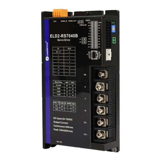
User Manual of ELD2-RS DC Servo ELD2-RS Series Servo Drive (7040B/7060B) Modbus Baud Rate/Terminal Communication Port Resistor Switch Safe Torque Off (STO) RS232 Tuning Port Indicator LED (PWR/ALM) ID Spin Dial (RSC-1) I/O Port ENC Encoder Port Motor Power Output... -
Page 14: Chapter 2 Installation & Wiring
User Manual of ELD2-RS DC Servo Chapter 2 Installation & Wiring 2.1 Servo Drive Installation 2.1.1 Servo drive installation environment Storage: -20~+65℃ (Condensation free); Temperature Installation: -20~+45℃ ( Please allow air circulation if >45℃) Humidity Under 90%RH (Condensation free) Altitude Up to 1000m above sea level Atmospheric 86 ~ 106kPa... - Page 15 User Manual of ELD2-RS DC Servo Dimension 2: ELD2-RS7015B/7020B/7030B Dimension 3: ELD2-RS7040B/7060B...
- Page 16 User Manual of ELD2-RS DC Servo Space requirement for installation 1. Please install the drive vertical to ground. 2. Please ensure optimal heat dissipation with enough room (>50mm) between each drives or to surrounding. It is recommended to install cooling fans for drives to achieve optimal performance. Please allow a gap larger than 50mm between drives and surrounding Please refer to the diagram above for a visual guide on how to properly install the DC servo...
-
Page 17: Servo Motor Installation
User Manual of ELD2-RS DC Servo 2.2 Servo Motor Installation 2.2.1 Installation conditions Installation conditions may affect the lifespan of a motor Please keep away from corrosive fluid and combustibles. If dusty working environment is unavoidable, please use motors with oil seal. ... -
Page 18: Eld2-Rs Wiring Diagram
User Manual of ELD2-RS DC Servo 2.3 ELD2-RS Wiring Diagram ELD2-RS Wiring Diagram Make sure data transferring cables are as short as possible. Keep CN1 cable under 3m and CN2 cable under 10m. Use shielded double winding cables to cut down on electromagnetic interference. -
Page 19: Servo Drive Ports
User Manual of ELD2-RS DC Servo 2.4 Servo Drive Ports ELD2-RS 7005/7010/7015B/7020B/7030B CN5 Modbus Communication Port Baud Rate/Terminal Resistor Switch CN7 RS232 Tuning Port Indicator LED (PWR/ALM) ID Spin Dial (RSC-1) I/O Port (CN1) ENC Encoder Port CN3 Motor Power Output (U, V, W, PE) CN3 Main Power Supply (DC+, GND) - Page 20 User Manual of ELD2-RS DC Servo ELD2-RS 7040B/7060B CN5 Modbus Communication Port Baud Rate/Terminal Resistor Switch CN6 Safe Torque Off CN7 RS232 Tuning (STO) Port Indicator LED (PWR/ALM) ID Spin Dial (RSC-1) CN9 Logic Circuit Power I/O Port (CN1) Supply ENC Encoder Port CN3 Motor Power Output (U, V, W, PE)
-
Page 21: Cn1&Cn2 I/O Signal Port
User Manual of ELD2-RS DC Servo 2.4.1 CN1 I/O Signal Port Diagram Signal Description DI1+ Pulse input, differential, 500kHz DI1+ DI2+ Direction input, differential, 500kHz DI2+ COM_IN Common DI Servo enable Alarm clear Homing switch Position limit Analog input, voltage -10-+10VDC, resistance 20kΩ... - Page 22 User Manual of ELD2-RS DC Servo Pulse input Pulse and direction input only support 5V signal. Please connect in series a resistor with resistance of 2kΩ for 24V pulse and direction signal. Please refer to the following differential and single-ended input wiring diagrams.
- Page 23 User Manual of ELD2-RS DC Servo >4μs >5μs <0.2μs <0.3μs <0.2μs <0.3μs >1μs >2.5μs I/O Signal Wiring Diagram 1. DI3-DI6 supports NPN and PNP configuration. Recommended to use an external control signal power s supply of 12-24VDC. 2. DO1-DO2 are single ended outputs with 100mA current output that supports NPN and PNP configuration.
-
Page 24: Cn3/Cn4 Power Supply & Regenerative Resistor Port
User Manual of ELD2-RS DC Servo 2.4.2 CN3/CN4 Power supply & Regenerative Resistor Port Port Signal Description DC Power Supply positive and negative terminals U, V, W, PE terminals for motor DC Power Supply positive and negative terminals 2.4.3 CN5 Modbus RS485 Communication Port Port Diagram Signal... -
Page 25: Cn6 Safe Torque Off (Sto) Port
User Manual of ELD2-RS DC Servo 2.4.4 CN6 Safe Torque Off (STO) Port Port Diagram Signal Description Remarks 24v power supply Connect to SF1 and SF2 when not in use. Do not Reference ground use to supply power. STO 1 positive input STO1+ STO 1 negative input STO1-... -
Page 26: Cn7 Rs232 Tuning Port
It is recommended to use an isolated power supply for STO signal input as any current leakage might cause STO malfunction. 2.4.5 CN7 RS232 Tuning Port Port Diagram Signal ELD2-RS Series DC Servo Drive can be connected to Motion Studio for parameters tuning and data monitoring using CABLE-PC-1. -
Page 27: Cn9 Logic Circuit Power Supply Port
User Manual of ELD2-RS DC Servo 2.4.6 CN9 Logic Circuit Power Supply Port Port Diagram Signal Description 24V positive terminal 24V negative terminal ELD2-RS7040B/7060B dual-axis DC servo drives include an optional logic circuit power supply port. When main power supply is cut, logic circuit power supply port can be connected to realize: 1. -
Page 28: Id Spin Dial Rsc
User Manual of ELD2-RS DC Servo Note: Molex 55959-1230 Connector Header (Driver side) Molex 51353-1200 12-pin rectangle connector 1pcs for each axis (Provided) Molex 56134-9000 female terminal reel 12pcs for each axis (Provided) 2.4.8 ID spin dial RSC Diagram Modbus address Modbus address... -
Page 29: Cable Selection
Wire length available: 0.5m, 1.5m, 3m, 5m, 7m and 10m. Connectors type available: SP21 connector Please contact Leadshine sales team or any Leadshine certified local retailers for any customized needs. *M*: Length of the cable Motor Power Cable CABLE-RZD*M*-263 12AWG... - Page 30 User Manual of ELD2-RS DC Servo Motor Power Cable CABLE-RZD*M*-143 16AWG Motor side Driver side Driver cable pin Pins Motor Color Driver White Black Yellow- green Motor Power Cable CABLE-RZD*M*-123 18AWG Motor side Driver side Driver cable pin Pins Motor Color Driver White...
- Page 31 User Manual of ELD2-RS DC Servo Motor Power Cable CABLE-RZD*M*-282 – 130 Frame Motor without brake Motor side Driver side Motor cable pin Pins Motor Color Driver White Black Yellow- green Motor Power Cable CABLE-RSZD*M*-282 – 130 Frame Motor with brake Motor side Driver side Motor cable pin...
-
Page 32: Motor Encoder Cable
User Manual of ELD2-RS DC Servo • Grounding: Grounding wire should be thicker. Ground PE terminal of servo drive and servo motor together with resistance <100 Ω. • Connect a line filter to power supply to reduce electromagnetic interference. • Please install a fuseless circuit breaker to cut off power supply in time when the driver fails. - Page 33 User Manual of ELD2-RS DC Servo For ELVM series motors with 130 flange size CABLE-BMD*M*-212 for single turn encoder Motor side Driver side Motor cable pin Color Signal Motor Drive Braid Shield Red- white Blue Blue- Black Motor side Driver side CABLE-BMAD*M*-222 with battery kit for multiturn absolute encoder Motor side Driver side...
-
Page 34: Motor Brake Cable
User Manual of ELD2-RS DC Servo 2.5.3 Motor Brake Cable CABLE-SCD*M*-113 Motor side Driver side - 22AWG cables *Note: Black – 0V, Red – 24V 2.5.4 Drive Communication Cable CABLE-TX*M*-LD2 - For CANopen and Modbus RS485 communication between drives/controller. 2.5.4 Tuning Cable CABLE-PC-1 - To connect to Motion Studio 2 PC tuning software. -
Page 35: Regenerative Resistor Selection
User Manual of ELD2-RS DC Servo 2.6 Regenerative Resistor Selection The use of regenerative resistor When the motor opposes the direction of rotation as in deceleration or vertical axis escalation, part of the regenerative energy will be delivered back to the driver. This energy will first be stored in internal capacitors of the driver. - Page 36 User Manual of ELD2-RS DC Servo Theoretical selection of regenerative resistor Without external loading torque, the need for an external regenerative resistor can be determined as the flow chart below Start T is the time for velocity to reach Determine the max.
- Page 37 User Manual of ELD2-RS DC Servo Diagram below shows the acceleration and deceleration cycle periods and the regenerative torque that occurs during the process. V:Motor rotational velocity Rotational velocity :Deceleration time Motor Torque : Load torque Regenerative torque Steps to calculate capacity of regenerative resistor Steps Calculation Symbol...
- Page 38 User Manual of ELD2-RS DC Servo Internal capacitor capacity and rotor inertia Rotor Inertia Max. regenerative energy ELD2 Drives Servo motor (× 10 kg.m stored in capacitor Ec(J) ) 750W (7020B) ELVM8075V48FH-M17 2.26 1000W (7030B) ELVM80100V48FH-M17 1.79 2.26 There are motors with low, medium and high inertia. Different motor models have different rotor inertia. Please refer to product catalogue for more information on rotor inertia.
-
Page 39: Chapter 3 Parameter
User Manual of ELD2-RS DC Servo Chapter 3 Parameter 3.1 Parameters list P r 0 . 0 0 Sub-code Classification code Valid mode: P: Valid in position control mode S: Valid in velocity control mode T: Valid in torque control mode PR: Valid in PR control mode Activation: “O”... - Page 40 User Manual of ELD2-RS DC Servo Valid mode Communication mode Activ Code Label Default ation Byte Addr. Regenerative resistor power rating Pr0.17 — 16bit 0x0023 Vibration suppression after stopping Pr0.18 — 16bit Micro-vibration suppression — Pr0.19 16bit External pulse valid edge settings Pr0.20 —...
- Page 41 User Manual of ELD2-RS DC Servo Valid mode Communication mode Activ Code Label Default ation Byte Addr. notch frequency Pr2.04 4000 — 16bit 0x0209 Pr2.05 notch width — 16bit 0x020B notch depth Pr2.06 — 16bit 0x020D Pr2.07 notch frequency — 4000 16bit 0x020F...
- Page 42 User Manual of ELD2-RS DC Servo Valid mode Communication mode Activ Code Label Default ation Byte Addr. Pr3.28 Position gain - Logistics — — — 16bit Pr3.29 Delay time gain - Logistics — — — 16bit [Class 4] I/O Monitoring Settings Valid mode Communication mode Activ...
- Page 43 User Manual of ELD2-RS DC Servo [Class 5] Extension settings Valid mode Communication mode Activ Code Label Default ation Byte Addr. 0x0500 — — Pr5.00 2nd pulse count per revolution 10000 32bit 0x0501 2nd Command frequency divider/multiplier 0x0502 Pr5.01 — —...
- Page 44 User Manual of ELD2-RS DC Servo [Class 6] Other Settings Valid mode Communication mode Activ Code Label Default ation Byte Addr. Pr6.01 Encoder zero position compensation 16bit 0x0603 — — — Pr6.03 JOG trial run torque command 16bit 0x0607 — Pr6.04 JOG trial run velocity command 16bit...
- Page 45 User Manual of ELD2-RS DC Servo [Class 8] Pr-Control Parameters Valid mode Communication mode Activ Code Label Default ation Byte Addr. Pr8.00 — — — PR Control 16bit 0x6000 Pr8.01 — — — Path count 16bit 0x6001 Pr8.02 — — —...
- Page 46 User Manual of ELD2-RS DC Servo Valid mode Communication mode Activ Code Label Default ation Byte Addr. Pr8.61 Path 13 S-code — — — 16bit 0x603D Pr8.62 — — — Path 14 S-code 16bit 0x603E Pr8.63 — — — Path 15 S-code 16bit 0x603F [Class 9] Pr-Control Path Parameters...
- Page 47 User Manual of ELD2-RS DC Servo Valid mode Communication mode Activ Code Label Default ation Byte Addr. Pr9.40 PR5 mode — — — 16bit 0x6228 Pr9.41 — — — PR5 position H 16bit 0x6229 Pr9.42 — — — PR5 position(L) 16bit 0x622A Pr9.43...
- Page 48 User Manual of ELD2-RS DC Servo Valid mode Communication mode Activ Code Label Default ation Byte Addr. Pr9.88 PR11 mode — — — 16bit 0x6258 Pr9.89 — — — PR11 position H 16bit 0x6259 Pr9.90 — — — PR11 position(L) 16bit 0x625A Pr9.91...
- Page 49 User Manual of ELD2-RS DC Servo [Class B] Status Parameters Valid mode Communication mode Activ Code Label Default ation Byte Addr. Software version 1(DSP) — PrB.00 16bit 0x0B00 Software version 2(CPLD) — PrB.01 16bit 0x0B01 Software version 3(Others) — PrB.02 16bit 0x0B02 PrB.03...
-
Page 50: Parameters Description
User Manual of ELD2-RS DC Servo 3.2 Parameters description 3.2.1 [Class 0] Basic Settings Label Model-following/Zero tracking control Valid mode(s) Pr0.00 Range 0-10000 Unit 0.1Hz Default Byte length 16bit Attribute 485 address 0x0001 Valid At stop Model-following bandwidth, also known as model-following control (MFC), is used to control the position loop to improve the responsiveness to commands, speed up positioning time and reduce following error. - Page 51 User Manual of ELD2-RS DC Servo Label Real time Auto Gain Adjusting Valid mode(s) Range Unit Default 0x0~0xFF — Pr0.02 Byte length 16bit Attribute 485 address 0x0005 Valid Immediate Value Category Settings Application Used to set motion setting mode, which can be selected according to the motion characteristics or setting requirements.
- Page 52 User Manual of ELD2-RS DC Servo Label Real time auto stiffness adjusting Valid mode(s) Range 0 ~ 31 Unit — Default Pr0.03 Byte length 16bit Attribute 485 address 0x0007 Valid Immediate High Mechanical stiffness Servo gain High 81.80……………………………70.69.68…………………………51.50 Responsiveness High Lower values ensure better system responsiveness and mechanical stiffness but machine vibration might occur, please set accordingly.
- Page 53 User Manual of ELD2-RS DC Servo Command pulse input mode Label Valid mode(s) Range Unit — Default Pr0.07 Byte length 16bit Attribute 485 address 0x000F Valid After restart Command pulse input Command Command pulse Polarity Command Pulse input mode Positive signal Negative signal inversion Mode...
- Page 54 User Manual of ELD2-RS DC Servo 1st command pulse count per Label Valid mode(s) revolution Range Unit Default 0-67100864 10000 PULSE Pr0.08 Byte length 32bit Attribute 485 address H: 0x0010 L: 0x0011 Valid After restart Control will affected if value set is too low. Err1b1 might occur if value < 500. (1) Pr0.08 valid when ≠...
- Page 55 User Manual of ELD2-RS DC Servo Excessive position deviation Label Valid mode(s) Pr0.14 Range 0~310 Unit 0.1rev Default Byte length 16bit Attribute 485 address 0x001D Valid Immediate Please set threshold value for position deviation accordingly. Default factory setting = 30, Er180 will be triggered if positive deviation is in excess of 3 revolutions.
-
Page 56: Class 1] Gain Adjustments
User Manual of ELD2-RS DC Servo ELD2-RS7040B 150/200 ELD2-RS7060B 150/200 Pr0.16 and Pr0.17 determines the threshold value of Er120. Please set accordingly or it might trigger false alarm or damage to servo drive. Note: If external regenerative resistor is used, please set according to its labeled power rating. - Page 57 User Manual of ELD2-RS DC Servo velocity detection filter Label Valid mode(s) Range Unit Default 0~31 — Pr1.03 Byte length 16bit Attribute 485 address 0x0107 Valid Immediate This filter is a low pass filter. It blocks high frequencies which cause system instability from velocity feedback data.
- Page 58 User Manual of ELD2-RS DC Servo Label Position Loop Gain Valid mode(s) Range Unit Default 0~30000 0.1/s Pr1.05 Byte length 16bit Attribute 485 address 0x010B Valid Immediate Label velocity loop gain Valid mode(s) Range Unit Default 1~32767 0.1Hz Pr1.06 Byte length 16bit Attribute 485 address...
- Page 59 User Manual of ELD2-RS DC Servo Label Torque feed forward gain Valid mode(s) Range Unit Default 0~1000 0.1% Pr1.12 Byte length 16bit Attribute 485 address 0x0119 Valid Immediate Before using torque feed forward, please set correct inertia ratio Pr0.04. By increasing torque feed forward gain, position deviation on constant acceleration/deceleration can be reduced to close to 0.
- Page 60 User Manual of ELD2-RS DC Servo Position control gain switching Label Valid mode(s) mode Range Unit Default 0~10 — Pr1.15 Byte length 16bit Attribute 485 address 0x011F Valid Immediate In position control, set the conditions for gain switching to be valid. Value Condition Gain switching condition...
- Page 61 User Manual of ELD2-RS DC Servo Hysteresis at position control Label Valid mode(s) switching Range Unit Default Mode 0~20000 Pr1.18 dependent Byte length 16bit Attribute 485 address 0x0125 Valid Immediate To eliminate the instability of gain switching. Used in combination with Pr1.17 using the same unit.
-
Page 62: Class 2] Vibration Suppression
User Manual of ELD2-RS DC Servo 3.2.3 [Class 2] Vibration suppression Label Adaptive filtering mode settings Valid mode(s) Range Unit — Default Pr2.00 Byte length 16bit Attribute 485 address 0x0201 Valid Immediate Value Description Adaptive filter: invalid Parameters related to 3 notch filter remain unchanged Adaptive filter: 1 filter valid... - Page 63 User Manual of ELD2-RS DC Servo Label notch frequency Valid mode(s) Range Unit Default 50~4000 4000 Pr2.04 Byte length 16bit Attribute 485 address 0x0209 Valid Immediate Set center frequency of 2 torque command notch filter. Set Pr2.04 to 4000 to deactivate notch filter notch width Label Valid mode(s)
- Page 64 User Manual of ELD2-RS DC Servo Label damping frequency Valid mode(s) Range Unit Default 0/10~2000 0.1Hz Pr2.14 Byte length 16bit Attribute 485 address 0x021D Valid Immediate Set Pr2.16 to 0 to deactivate this parameter. To suppress wobble at load end. Often used when wobble of flexible structure due to high deceleration upon stopping.
- Page 65 User Manual of ELD2-RS DC Servo Label Valid mode(s) Position command FIR filter Range Unit Default 0~2500 0.1ms Pr2.23 Byte length 16bit Attribute 485 address 0x022F Valid At stop As shown below, when target velocity Vc square wave command reaches Vc, it becomes trapezoidal wave after filtering.
-
Page 66: Class 3] Velocity/Torque Control
User Manual of ELD2-RS DC Servo 3.2.4 [Class 3] Velocity/Torque control Label Velocity internal/external switching Valid mode(s) Range Unit — Default Pr3.00 Byte length 16bit Attribute 485 address 0x0301 Valid Immediate Connect to the right DI to control internal command velocity settings. Value Velocity settings Analog - Velocity command(SPR)... - Page 67 User Manual of ELD2-RS DC Servo Velocity command rotational Label Valid mode(s) direction selection Range Unit Default — Pr3.01 Byte length 16bit Attribute 485 address 0x0303 Valid Immediate To set positive/negative direction of velocity command Velocity settings Velocity command Velocity command (Analog or internal sign selection(VC- Value...
- Page 68 User Manual of ELD2-RS DC Servo Velocity command input inversion Label Valid mode(s) Range Unit Default — Pr3.03 Byte length 16bit Attribute 485 address 0x0307 Valid Immediate To set voltage polarity of analog velocity command. Only valid when Pr3.01 = 0. When Pr3.01 = 1, rotational direction is only related to VC-SIGN. Value Motor rotational direction 【0】...
- Page 69 User Manual of ELD2-RS DC Servo Acceleration time settings Label Valid mode(s) Range Unit Default 0~10000 (1000rpm) Pr3.12 Byte length 16bit Attribute 485 address 0x0319 Valid Immediate Label Deceleration time settings Valid mode(s) Range Unit Default 0~10000 (1000rpm) Pr3.13 Byte length Attribute 485 address 16bit...
- Page 70 User Manual of ELD2-RS DC Servo Sigmoid acceleration/deceleration Label Valid mode(s) settings Range Unit Default 0~1000 Pr3.14 Byte length 16bit Attribute 485 address 0x031D Valid After restart To set sigmoid acceleration and deceleration turning point in accordance to Pr3.12 and Pr3.13.
- Page 71 User Manual of ELD2-RS DC Servo Torque command direction selection Label Valid mode(s) Range Unit Default — Pr3.18 Byte length 16bit Attribute 485 address 0x0325 Valid Immediate To set torque command positive/negative direction Value Direction settings TC-SIGN ON/OFF has no effect on torque direction 【0】...
- Page 72 User Manual of ELD2-RS DC Servo Label Velocity limit in torque mode Valid mode(s) Range Unit Default 0~10000 r/min Pr3.21 Byte length 16bit Attribute 485 address 0x032B Valid Immediate To set velocity limit in torque control mode. Only valid when Pr3.17 = 0 / 2. Label Torque command Valid mode(s)
-
Page 73: Class 4]I/O Monitoring Settings
User Manual of ELD2-RS DC Servo 3.2.5 [Class 4]I/O Monitoring Settings Label Input selection DI3 Valid mode(s) Range Unit Default 0x00~0xFF — Pr4.00 Byte length Attribute 485 address 16bit 0x0401 Valid Immediate Please refer to the table below to set DI signals and table on the right for corresponding pin and parameters Value Symbol Signal... - Page 74 User Manual of ELD2-RS DC Servo Negative limit Origin Path address 0 ADD0 Path address 1 ADD1 Path address 2 ADD2 Path address 3 ADD3 Note: CTRG, HOME are edge triggered, please make sure electronic bits last 1ms or above. Label Input selection DI4 Valid mode(s)
- Page 75 User Manual of ELD2-RS DC Servo Same signal can be assigned to multiple different outputs. Normally open(NO):Active low Normally close(NC):Active high Err212 might occur if output is allocated to signals other than listed in the table above. Outputs related to PR-mode Value Signal Symbol...
- Page 76 User Manual of ELD2-RS DC Servo Label Positioning complete range Valid mode(s) Range Unit Default 0~ Pr5.21 set unit 10000 Pr4.31 Byte length Attribute 485 address 16bit 0x043F Valid Immediate To set position deviation range of INP1 positioning completed output signal. INP1 output signal will be valid once position is complete within the range of deviation set.
- Page 77 User Manual of ELD2-RS DC Servo Zero speed Label Valid mode(s) Range Unit Default 1~2000 r/min Pr4.34 Byte length Attribute 485 address 16bit 0x0445 Valid Immediate To set threshold value for zero speed clamp detection. Zero speed clamp detection (ZSP) output signal valid when motor speed goes under the value set in Pr4.34 - Disregard the direction of rotation, Speed...
- Page 78 User Manual of ELD2-RS DC Servo Reached velocity Label Valid mode(s) Range Unit Default 10~2000 r/min 1000 Pr4.36 Byte length 16bit Attribute 485 address 0x0449 Valid Immediate When motor velocity > Pr4.36, AT-speed output signal is valid. Detection using 10RPM hysteresis. Holding brake deactivation delay time Label Valid mode(s)
- Page 79 User Manual of ELD2-RS DC Servo *1: Delay time set in Pr4.38 *2: Delay time from the moment BRK_OFF signal is given until actual holding brake is released or BRK_ON signal is given until actual holding brake is activated. It is dependent on the holding brake of the motor.
-
Page 80: Class 5] Extension Settings
User Manual of ELD2-RS DC Servo 3.2.6 [Class 5] Extension Settings pulse count per revolution Label Valid mode(s) Range Unit Default 0-67108864 10000 PULSE Pr5.00 Byte length 32bit Attribute 485 address H: 0x0500 L: 0x0501 Valid After restart Switch between Pr0.08 and Pr5.00 with DI signal DIV1. When switch to Pr5.00: (1)Pr5.00 valid when ≠... - Page 81 User Manual of ELD2-RS DC Servo To set servo driver disable mode and status. Set value Explanation Driver disables after velocity reaching value set in Pr4.39 Driver disables immediately, axis in free stopping mode Valid mode(s) Label Servo braking torque setting Range Default 0~500...
- Page 82 User Manual of ELD2-RS DC Servo Label Position unit settings Valid mode(s) Range — Default Unit Pr5.20 Byte length 16bit Attribute 485 address 0x0529 Valid Immediate Set unit for position related parameters Value Unit Encoder unit Command unit 0.0001rev Command unit: Pulse from host (Affected by electronic gear ratio) Encoder unit: Pulse from encoder (Related to encoder resolution) Pr5.20 can only be modified when axis is disabled as it will clear position data Torque limit selection...
- Page 83 User Manual of ELD2-RS DC Servo RS485 communication mode Valid mode(s) Label Range — Default 0~255 Unit Pr5.29 Byte length 16bit Attribute 485 address 0x053B Valid After restart Value Checksum Stop Even Even Null Null 【5】 RS485 communication Baud rate Valid mode(s) Label —...
-
Page 84: Class 6] Other Settings
User Manual of ELD2-RS DC Servo 3.2.7 [Class 6] Other settings Label Encoder zero position compensation Valid mode(s) Range Electrical Default 0~360 Unit angel Pr6.01 Byte length 16bit Attribute 485 address 0x0603 Valid Power-off Zero position compensation for encoder zero drift to avoid abnormality due to zero drift. Label JOG trial run torque command Valid mode(s) - Page 85 User Manual of ELD2-RS DC Servo Above diagram is illustrated using Pr1.15 = 7. gain= 1 gain * Pr6.06/100 gain valid when Pr6.05 ≠ 0. Set 3 Only effective under position control mode. 3 gain value in Pr6.06. When 2 gain switches to 1 gain, it will go through 3 , switching time is set in...
- Page 86 User Manual of ELD2-RS DC Servo Max. time to stop after disabling Valid mode(s) Label Range 0~1000 Unit Default Pr6.14 Byte length 16bit Attribute 485 address 0x061D Valid Immediate To set the max. time allowed for the axis to stop on emergency stop or normal axis disabling. After disabling axis, if motor speed is still higher than Pr4.39 but the time set in Pr6.14 is reached, BRK_ON given and holding brake activated.
- Page 87 User Manual of ELD2-RS DC Servo Valid mode(s) Label Shaft lock current raising time Range Default Unit 0~32767 Pr6.28 Byte length 16bit Attribute 485 address 0x0639 Valid Immediate Label Valid mode(s) Shaft lock duration time Range μs Default 0~32767 Unit Pr6.29 Byte length 16bit...
-
Page 88: Class 7] Factory Settings
User Manual of ELD2-RS DC Servo Absolute multiturn data upper limit Valid mode(s) Label Range Default 0~32766 Unit Pr6.63 Byte length 16bit Attribute 485 address 0x067F Valid After restart Use Pr0.15 = 2 in rotational mode, Feedback position cycles between 0 and (Pr6.63+1) x encoder resolution. -
Page 89: Class 8] Pr Control Parameters
User Manual of ELD2-RS DC Servo 3.2.9 [Class 8] PR control parameters Label PR Control Valid mode(s) Range Default Pr8.00 0 ~ 65535 Unit Byte length 16bit Attribute 485 address 0X6000 It is recommended to modify PR control parameters using Motion Studio. Description =1, absolute value =1, homing... - Page 90 User Manual of ELD2-RS DC Servo Valid mode(s) Label Software positive limit (L) Range Default -2147483648~ Pr8.07 Unit Pulse 2147483647 Byte length 32bit Attribute 485 address 0X6007 To set software positive limit position (32 bit base) Using 485 communication, only able to R/W low 16 bit. R/W high 16 bit needs to be realized through Pr8.06 When software positive limit = 994817, 0x000F2E01(Hexadecimal) high16bit = 0x000F, hence Pr8.05 reading = 0x000F, controller = 15.
- Page 91 User Manual of ELD2-RS DC Servo Label Home position offset H Valid mode(s) Range Default 0 ~ 65535 Unit Pr8.13 Byte length 16bit Attribute 485 address 0X600D High bit of home position offset;(Only valid using 485 communication) Valid mode(s) Label Home position offset (L) Range -2147483648~...
- Page 92 User Manual of ELD2-RS DC Servo Valid mode(s) Label STP emergency stop deceleration Range Default Pr8.23 1 ~ 32767 Unit ms/Krpm Byte length 16bit Attribute 485 address 0X6017 To set STP emergency stop deceleration. Label I/O combination trigger mode Valid mode(s) Range Default Pr8.26...
- Page 93 User Manual of ELD2-RS DC Servo Label S-code current output value Valid mode(s) Range Default 0 ~ 65535 Unit Pr8.28 Byte length 16bit Attribute 485 address 0X601C S-code(Status code)is the S-code of currently operating PR positioning data. Every PR path has a S-code setting. S-code Sx.H Sx.L...
- Page 94 User Manual of ELD2-RS DC Servo Valid mode(s) Label JOG deceleration Range Default Pr8.41 0 ~ 65535 Unit ms/Krpm Byte length Attribute 485 address 16bit 0X6029 Set JOG deceleration in PR mode. Valid mode(s) Label Command position H Range Default 0 ~ 65535 Unit Pr8.42...
- Page 95 User Manual of ELD2-RS DC Servo Label Path 2 S-code Valid mode(s) Range Default Pr8.50 0 ~ 65535 Unit Byte length 16bit Attribute 485 address 0X6032 Please refer to Pr8.28 for S-code setting. Label Path 3 S-code Valid mode(s) Range Default Pr8.51 0 ~ 65535...
- Page 96 User Manual of ELD2-RS DC Servo Label Valid mode(s) Path 12 S-code Range Default Pr8.60 Unit 0 ~ 65535 Byte length 16bit Attribute 485 address 0X603C Please refer to Pr8.28 for S-code setting. Label Valid mode(s) Path 13 S-code Range Default Pr8.61 Unit...
-
Page 97: Class 9] Pr Control Path Parameters
User Manual of ELD2-RS DC Servo 3.2.10 [Class 9] PR control path parameters It is more convenient to set Class 9 parameters on Motion Studio Valid mode(s) Label PR0 mode Pr9.00 Range 0x0~0xFFFF Unit Default Byte length 16bit Attribute 485 address 0X6200 8-13 Definition... - Page 98 User Manual of ELD2-RS DC Servo Valid mode(s) Label PR1 mode Pr9.08 Range 0x0~0xFFFF Unit Default Byte length 16bit Attribute 485 address 0X6208 8-13 Definition 0: No 0-15: 0: absolute 0: No 0: Can be 0: null Jump, Jump to 1: correspond overlap, Interrupt...
- Page 99 User Manual of ELD2-RS DC Servo Valid mode(s) Label PR2 mode Pr9.16 Range 0x0~0xFFFF Unit Default Byte length 16bit Attribute 485 address 0X6210 8-13 Definition 0: No 0-15: 0: absolute 0: No 0: Can be 0: null Jump, Jump to 1: correspond overlap, Interrupt...
- Page 100 User Manual of ELD2-RS DC Servo Valid mode(s) Label PR3 mode Pr9.24 Range 0x0~0xFFFF Unit Default Byte length 16bit Attribute 485 address 0X6218 8-13 Definition 0: No 0-15: 0: absolute 0: No 0: Can be 0: null Jump, Jump to 1: correspond overlap, Interrupt...
- Page 101 User Manual of ELD2-RS DC Servo Valid mode(s) Label PR4 mode Pr9.32 Range 0x0~0xFFFF Unit Default Byte length 16bit Attribute 485 address 0X6220 8-13 Definition 0: No 0-15: 0: absolute 0: No 0: Can be 0: null Jump, Jump to 1: correspond overlap, Interrupt...
- Page 102 User Manual of ELD2-RS DC Servo Valid mode(s) Label PR5 mode Pr9.40 Range 0x0~0xFFFF Unit Default Byte length 16bit Attribute 485 address 0X6228 8-13 Definition 0: No 0-15: 0: absolute 0: No 0: Can be 0: null Jump, Jump to 1: correspond overlap, Interrupt...
- Page 103 User Manual of ELD2-RS DC Servo Valid mode(s) Label PR6 mode Pr9.48 Range 0x0~0xFFFF Unit Default Byte length 16bit Attribute 485 address 0X6230 8-13 Definition 0: No 0-15: 0: absolute 0: No 0: Can be 0: null Jump, Jump to 1: correspond overlap, Interrupt...
- Page 104 User Manual of ELD2-RS DC Servo Valid mode(s) Label PR7 mode Pr9.56 Range 0x0~0xFFFF Unit Default Byte length 16bit Attribute 485 address 0X6238 8-13 Definition 0: No 0-15: 0: absolute 0: No 0: Can be 0: null Jump, Jump to 1: correspond overlap, Interrupt...
- Page 105 User Manual of ELD2-RS DC Servo Valid mode(s) Label PR8 mode Pr9.64 Range 0x0~0xFFFF Unit Default Byte length 16bit Attribute 485 address 0X6240 8-13 Definition 0: No 0-15: 0: absolute 0: No 0: Can be 0: null Jump, Jump to 1: correspond overlap, Interrupt...
- Page 106 User Manual of ELD2-RS DC Servo Valid mode(s) Label PR9 mode Pr9.72 Range 0x0~0xFFFF Unit Default Byte length 16bit Attribute 485 address 0X6248 8-13 Definition 0: No 0-15: 0: absolute 0: No 0: Can be 0: null Jump, Jump to 1: correspond overlap, Interrupt...
- Page 107 User Manual of ELD2-RS DC Servo Valid mode(s) Label PR10 mode Pr9.80 Range 0x0~0xFFFF Unit Default Byte length 16bit Attribute 485 address 0X6250 8-13 Definition 0: No 0-15: 0: absolute 0: No 0: Can be 0: null Jump, Jump to 1: correspond overlap, Interrupt...
- Page 108 User Manual of ELD2-RS DC Servo Valid mode(s) Label PR11 mode Pr9.88 Range 0x0~0xFFFF Unit Default Byte length 16bit Attribute 485 address 0X6258 8-13 Definition 0: No 0-15: 0: absolute 0: No 0: Can be 0: null Jump, Jump to 1: correspond overlap, Interrupt...
- Page 109 User Manual of ELD2-RS DC Servo Valid mode(s) Label PR12 mode Pr9.96 Range 0x0~0xFFFF Unit Default Byte length 16bit Attribute 485 address 0X6260 8-13 Definition 0: No 0-15: 0: absolute 0: No 0: Can be 0: null Jump, Jump to 1: correspond overlap, Interrupt...
- Page 110 User Manual of ELD2-RS DC Servo Valid mode(s) Label PR13 mode Pr9.104 Range 0x0~0xFFFF Unit Default Byte length 16bit Attribute 485 address 0X6268 8-13 Definition 0: No 0-15: 0: absolute 0: No 0: Can be 0: null Jump, Jump to 1: correspond overlap, Interrupt...
- Page 111 User Manual of ELD2-RS DC Servo Valid mode(s) Label PR14 mode Pr9.112 Range 0x0~0xFFFF Unit Default Byte length 16bit Attribute 485 address 0X6270 8-13 Definition 0: No 0-15: 0: absolute 0: No 0: Can be 0: null Jump, Jump to 1: correspond overlap, Interrupt...
- Page 112 User Manual of ELD2-RS DC Servo Valid mode(s) Label PR15 mode Pr9.120 Range 0x0~0xFFFF Unit Default Byte length 16bit Attribute 485 address 0X6278 8-13 Definition 0: No 0-15: 0: absolute 0: No 0: Can be 0: null Jump, Jump to 1: correspond overlap, Interrupt...
-
Page 113: Class B] Status Parameters
User Manual of ELD2-RS DC Servo 3.2.11 [Class B] Status Parameters Software version 1(DSP) Valid mode(s) Label PrB.00 Range Unit Default Byte length Attribute 485 address 16bit 0x0B00 Show DSP software version info. Label Software version 2(CPLD) Valid mode(s) PrB.01 Range Unit Default... - Page 114 User Manual of ELD2-RS DC Servo Label Motor speed (After filter) Valid mode(s) PrB.09 Range Unit Default Byte length 16bit Attribute 485 address 0x0B09 Motor speed after motor actual speed filtering Label DC bus voltage Valid mode(s) PrB.10 Range Unit Default Byte length 16bit...
- Page 115 User Manual of ELD2-RS DC Servo Valid mode(s) Label Command position (Command unit) Range Default Unit PrB.20 Byte length Attribute 485 address 32bit H: 0x0B14 L: 0x0B15 Driver receives command pulse count. Driver command unit: 10000 pulses/rev, Encoder unit: 8388608 pulses/rev. If driver receives 8388608 pulses, 10000P will be shown. Label Motor position (Command unit) Valid mode(s)
-
Page 116: Chapter 4 Control Mode
User Manual of ELD2-RS DC Servo Chapter 4 Control Mode Control modes for ELD2-RS series DC servo drives can be divided into 3 categories: Position control mode, Velocity control mode and Torque control mode. RS models also come with a hybrid control mode which is a combination of any 2 modes which are above. -
Page 117: Position Control
User Manual of ELD2-RS DC Servo 4.1 Position control Position control determines rotational speed by frequency of external input pulse and angle of rotation through pulse count using 5V pulse from motion controller, control card or 24V pulse (Please add 2kΩ resistor) for PLC. Applies where precise positioning is required. Velocity feedforward Torque... -
Page 118: Pulse Input And Direction Settings
User Manual of ELD2-RS DC Servo 4.1.1 Pulse input and direction settings Position command (pulse) input method: 1. A and B phase pulse 2. Positive/Negative direction pulse 3. Pulse count + symbol Set pulse mode, rotational direction and max. pulse input frequency according to actual need CN1 Pin Label Definition... -
Page 119: Electronic Gear Ratio
1. When Pr0.08 = 0, Pr0.09 and Pr0.10 will be valid. Other than that, Pr0.08 set value will be valid. 2. ELD2-RS series supports 2 independent sets of electronic gear ratio. The 2 sets can be switch by delivering a command frequency divider/multiplier input DIV1. Both sets of electronic gear ratio is set up using Pr0.08, Pr0.09 and Pr0.10;... -
Page 120: Position Command Filter
User Manual of ELD2-RS DC Servo 1. Settings: (1)Driver command pulse input count : X (2)Encoder pulse count after frequency divider/multiplier: Y (3)Encoder pulse count per revolution: Z (4)Motor revolution: W 2. Calculation: (1)X, Y Y = X * Pr0.09 / Pr0.10 Please keep the value of Pr0.09 and Pr0.10 to be smaller than 2 (16777216). - Page 121 User Manual of ELD2-RS DC Servo Label Position command FIR filter Valid mode(s) Range 0~2500 Unit 0.1ms Default Pr2.23 Byte length Attribute 485 address 16bit 0x022F Valid At stop As shown below, when target velocity Vc square wave command reaches Vc, it becomes trapezoidal wave after filtering.
-
Page 122: Encoder Feedback Output
User Manual of ELD2-RS DC Servo 4.1.4 Encoder feedback output Motor position feedback of A, B phase to master device (controller) in pulse Encoder output pulse count per Label Valid mode(s) revolution Pr0.11 Range 1~32767 Unit Default 2500 Byte length 16bit Attribute 485 address... -
Page 123: Positioning Completed Inp Signal Output
User Manual of ELD2-RS DC Servo 4.1.5 Positioning completed INP signal output INP signal output will be valid when position deviation is within the range when positioning is completed. Set unit in Pr5.20. Label Positioning complete range Valid mode(s) Range Unit Default 0~... -
Page 124: Velocity Control Mode
User Manual of ELD2-RS DC Servo 4.2 Velocity control mode Velocity mode precisely controls motor rotational speed/direction using analog velocity command or internal related parameters. There are 4 types of velocity control modes for ELD2- RS series DC Servo Drives: Analog control, internal velocity 4 speeds, internal velocity 8 speeds and analog + internal velocity control. -
Page 125: Velocity Command Input Control
User Manual of ELD2-RS DC Servo 4.2.1 Velocity command input control Set velocity control mode in Pr3.00 Pr3.00 = 0 Analog Pr3.00 = 1 Internal velocity Velocity command Pr3.00 = 2 direction Analog + Pr3.01 Internal velocity Pr3.00 = 3 Internal velocity Label... - Page 126 User Manual of ELD2-RS DC Servo Velocity command input inversion Set Analog-Velocity command (SPR) voltage polarity Velocity command input inversion Label Valid mode(s) Range Unit Default — Pr3.03 Byte length 16bit Attribute 485 address 0x0307 Valid Immediate To set voltage polarity of analog velocity command. Only valid when Pr3.01 = 0.
-
Page 127: Velocity Command Acceleration/Deceleration
User Manual of ELD2-RS DC Servo 4.2.2 Velocity command acceleration/deceleration Acceleration/Deceleration is added onto velocity command input to control velocity. This function is valid when entering step-like velocity command or internal velocity settings is used to realize motor soft start. Use Sigmoid acceleration/deceleration to reduce vibration and impact due to changes in velocity. -
Page 128: Velocity Reached Signal At-Speed Output
User Manual of ELD2-RS DC Servo To set sigmoid acceleration and deceleration turning point in accordance to Pr3.12 and Pr3.13. Velocity Velocity (RPM) after acceleration/ deceleration Target settings velocity ta= Vc/1000 x Pr3.12 x 1ms td= Vc/1000 x Pr3.13 x 1ms Ts = Pr3.14 x 1ms Use when ta/2>ts、td/2>ts Time... -
Page 129: Velocity Coincidence V-Coin Signal Output
User Manual of ELD2-RS DC Servo 4.2.4 Velocity coincidence V-COIN signal output V-COIN signal output will be valid when velocity command (before acceleration/deceleration) coincides with motor velocity. Velocity is considered to be coincided if the difference between velocity command before acceleration/deceleration from servo drive and motor velocity is within the value set in Pr4.35. This output function can be assigned through I/O configurations, please refer to Pr4.10. -
Page 130: Torque Control
User Manual of ELD2-RS DC Servo Valid Immediate Valid when Pr3.15 = 2/3, velocity command is forced to 0 when actual velocity is lower than Pr3.16 and after static time set in Pr3.23. 4.3 Torque control Torque control mode is to the size of motor asserted torque through external analogue input or directly from set value internally. -
Page 131: Torque Command Input Control
User Manual of ELD2-RS DC Servo 4.3.1 Torque command input control Torque control mode settings Torque control mode includes 3 control modes as shown below. Set torque control mode in Pr3.17. Pr3.17 = 0 Torque analogue + Pr3.21 Pr3.17 = 1 Torque analogue + Velocity analogue Torque command... - Page 132 User Manual of ELD2-RS DC Servo Torque command direction settings To switch velocity command direction through DI. Assign TC-SIGN signal to corresponding DI terminal and determine velocity command direction through digital input signal. Label Torque command direction selection Valid mode(s) Range Unit Default...
-
Page 133: Torque Velocity Limit
User Manual of ELD2-RS DC Servo 4.3.2 Torque velocity limit To set velocity limit in torque mode for safety reasons. Label Valid mode(s) Velocity limit in torque mode Range Unit Default 0~10000 r/min Pr3.21 Byte length 16bit Attribute 485 address 0x032B Valid Immediate... -
Page 134: Hybrid Control Mode
User Manual of ELD2-RS DC Servo 4.4 Hybrid Control Mode Hybrid control mode is for servo drive to be able to switch between different modes during operation. Hybrid control mode consists of the 3 listed below: • Position-velocity mode • Position-torque mode •... -
Page 135: Chapter 5 Application Case
User Manual of ELD2-RS DC Servo Chapter 5 Application Case 5.1 Gain Adjustment In order for servo driver to execute commands from master device without delay and to optimize machine performance, gain adjustment has to be done yet. High gain Low gain High gain + feedforward [r/min]... - Page 136 User Manual of ELD2-RS DC Servo Start Electronic gear ratio Inertia measuring Auto gain adjustment Requirement met? Manual gain adjustment Requirement met? Vibration suppression Gain Adjustment Flow Chart...
-
Page 137: Inertia Ratio Identification Function
User Manual of ELD2-RS DC Servo Steps Functions Explanation Online Motor moves with command from controller, servo driver will Inertia ratio automatically calculate load-inertia ratio identification Auto gain Auto gain Real time determining of mechanical load, gain value is set adjustment adjustment accordingly. - Page 138 User Manual of ELD2-RS DC Servo Online inertia determination Enable motor using controller. Let motor run at above 400rpm, make sure there are acceleration, constant velocity and deceleration phase during the whole run. Cycle through 2-3 times to calculate load-inertia ratio. Result can be found on the front panel d16 or through Motion Studio system monitoring page.
- Page 139 User Manual of ELD2-RS DC Servo 6. Click on “Parameter List” to enter parameters management to check or modify Pr0.04. Then, click on “Save” to save parameters to driver. Please take note: 1. Trial run velocity and distance should be optimal to prevent any axis from bumping into objects. 2.
-
Page 140: Auto Gain Adjustment
User Manual of ELD2-RS DC Servo 5.3 Auto gain adjustment This function will measure real time mechanical properties and set gain values in accordance to mechanical stiffness. Can be used in any control mode Conditions to implement Please refer to Pr0.02 for detailed explanations. Auto gain adjustment is Control mode different for each control mode. - Page 141 User Manual of ELD2-RS DC Servo There are 2 types of auto gain adjustment methods: • Standard mode (Pr0.02 = 0x__1): Basic mode, prioritizing on stability, gain switching is disabled. Actual gain auto adjustment as accordance to Pr0.03. Gain related parameters that change as shown below. Parameter Label Remarks...
- Page 142 User Manual of ELD2-RS DC Servo Types of mechanical load Please select mechanical load according to load-inertia ratio and mechanical structures: Load types Description 0x00_ : Rigid structure When load is rigid with relatively low inertia. Gain adjustments prioritize system responsiveness. Structures including high precision reducer, lead screws, mechanical gears, etc.
- Page 143 User Manual of ELD2-RS DC Servo Used to select the load type, choose according to load-inertia ratio and mechanical structure. This mode prioritizes system responsiveness. Use this mode 0: Rigid when there is a relatively rigid structure with low load inertia. structure Typical application including directly connected high-precision gearbox, lead screw, gears, etc.
- Page 144 User Manual of ELD2-RS DC Servo Gain parameters settings table gain gain Pr1.00 Pr1.01 Pr1.02 Pr1.04 Pr1.05 Pr1.06 Pr1.07 Pr1.09 Velocity loop Velocity loop Velocity Position Velocity Position Torque Torque integral time integral time loop loop loop loop gain filter filter constant constant...
-
Page 145: Manual Gain Adjustment
User Manual of ELD2-RS DC Servo 5.4 Manual gain adjustment Due to limitation of load conditions, automatic gain adjustment might not achieve expected performance. Control can be improved through manual gain adjustment The servo system is made up of 3 control loops. From outer to inner: position loop, velocity loop, current loop as shown in the diagram below. - Page 146 User Manual of ELD2-RS DC Servo Step Parameter Label Tuning method To eliminate velocity loop deviation Actual velocity Command Reduce Pr1.02 velocity Pr1.02 Velocity loop integral time Velocity loop integral time constant (ms) = 4000 / (2*π*Velocity loop gain(Hz)) constant Reduce Pr1.02 to reduce positioning time.
-
Page 147: Parameters Adjustment Under Different Control Modes
User Manual of ELD2-RS DC Servo 1. If vibration occurs with increasing Pr1.01, please modify Pr1.04 to suppress vibration. 2. If the parameters are set too high, it might cause current loop response to reduce. 3. To suppress vibration at stop, increase Pr1.01 and decrease Pr1.04. 4. - Page 148 User Manual of ELD2-RS DC Servo and 2 gain initial values are obtained by automatic gain adjustment Parameter Label Pr1.00 position loop gain Pr1.01 velocity loop gain Pr1.02 velocity integral time constant Pr1.03 velocity detection filter Pr1.04 torque filter time constant Pr1.05 position loop gain Pr1.06...
-
Page 149: Gain Switching
User Manual of ELD2-RS DC Servo 5.4.2 Gain switching Gain switching function can be triggered internally in servo driver. Only valid under position or velocity control mode. Following effects can be realized by gain switching: 1. Switch to lower gain when motor stops to suppress vibration 2. - Page 150 User Manual of ELD2-RS DC Servo Start Pr0.02 – Standard mode Set Pr0.02 Pr0.02 – Manual/ Positioning mode Gain switching Pr1.15=0 Pr1.15=1 Set Pr1.15 PA1.15=3/5/6/9/10 Pr1.17~Pr1.19 gain gain Switch gain accordingly Related parameters on gain switching Parameter Label Remarks In position control, set Pr1.15=3、5、 Position control gain Pr1.15 6、9、10.
- Page 151 User Manual of ELD2-RS DC Servo Label Position control gain switching mode Valid mode(s) Range Unit Default — 0~10 Pr1.15 Byte length 16bit Attribute 485 address 0x011F Valid Immediate In position control, set the conditions for gain switching to be valid. Value Condition Gain switching condition...
- Page 152 User Manual of ELD2-RS DC Servo Set threshold value for gain switching to occur. Unit is mode dependent. Switching condition Unit Position Encoder pulse count Velocity Torque Please set level ≥ hysteresis Label Hysteresis at position control switching Valid mode(s) Range Unit Mode...
-
Page 153: Rd Gain Switching
User Manual of ELD2-RS DC Servo 5.5 3 gain switching Besides switching between 1 and 2 gain, a 3 gain switching is added to set gain at the moment of stopping to reduce positioning time. Only available under position mode and Pr6.05 ≠ 0, set Pr6.06 for 3 gain value. -
Page 154: Model Following Control
User Manual of ELD2-RS DC Servo Above diagram is illustrated using Pr1.15 = 7. gain= 1 gain * Pr6.06/100 Only effective under position control mode. 3 gain valid when Pr6.05 ≠ 0. Set 3 gain value in Pr6.06. When 2 gain switches to 1 gain, it will go through 3 , switching time is set in Pr1.19. -
Page 155: Feedforward Gain
User Manual of ELD2-RS DC Servo Model following bandwidth determines the responsiveness of the servo system. Increase the value set will increase responsiveness and reduce positioning time. Overshoot can be prevented if it is set at a lower value but responsiveness will be lowered. Model following bandwidth shouldn’t be too large for mechanical structure with lower stiffness, excessive position deviation alarm might occur under high velocity. -
Page 156: Torque Feedforward
User Manual of ELD2-RS DC Servo Velocity feedforward application Set Pr1.11 to around 50 (0.5ms), then tune Pr1.10 from 0 to bigger values until the velocity feedforward achieves better performance. Under constant velocity, the position deviation in a motion will decrease as the velocity feedforward gain increase. Steps to tuning: Increase Pr1.10 to increase responsiveness but velocity overshoot might occur during acc- /deceleration. - Page 157 User Manual of ELD2-RS DC Servo Torque feedforward application Set Pr1.13 to around 50 (0.5ms), then tune Pr1.10 from 0 to bigger values until torque feedforward achieves better performance. Under constant acc-/deceleration, the position deviation in a motion will decrease as the velocity feedforward gain increase. Steps to tuning: Increase Pr1.12 to increase responsiveness but velocity overshoot might occur during acc- /deceleration.
-
Page 158: Friction Compensation Function
User Manual of ELD2-RS DC Servo 5.8 Friction compensation function This function is to compensation for changes in load to reduce the effect of friction in motion. The compensation value is directional. Velocity command Pr6.08 Pr6.07 Time Pr6.09 Velocity command Motor off Motor on Motor off... -
Page 159: Safety Functions
User Manual of ELD2-RS DC Servo Range Default -100~100 Unit Byte length Attribute 485 address 16bit 0x0613 Valid Immediate To reduce the effect of mechanical friction in the movement(s) of the axis. Compensation values can be set according to needs for both rotational directions. Applications: 1. -
Page 160: Max. Duration For Motor To Stop After Disabling
User Manual of ELD2-RS DC Servo 5.9.2 Max. duration for motor to stop after disabling Set max time duration for motor to stop after disabling. If the time taken for motor to stop exceeds the duration set in Pr6.14 and motor speed is still higher than Pr4.39, holding brake will be activated. If motor doesn’t have holding brake, dynamic braking will be activated to force stop the motor. - Page 161 User Manual of ELD2-RS DC Servo SRV_ON Brake released (BRK_ON) Brake BRK_OFF Motor Power Released Actual holding Braked Braked brake status Motor Velocity *1: Delay time set in Pr4.38 *2: Delay time from the moment BRK_OFF signal is given until actual holding brake is released or BRK_ON signal is given until actual holding brake is activated.
-
Page 162: Servo Stopping Mode
User Manual of ELD2-RS DC Servo 5.9.4 Servo stopping mode Label Valid mode(s) Servo-off mode Range Default Unit — Pr5.06 Byte length 16bit Attribute 485 address 0x050D Valid Immediate To set servo driver disable mode and status. Set value Explanation Driver disables after velocity reaching value set in Pr4.39 Driver disables immediately, axis in free stopping mode 5.9.5 Emergency stop function... - Page 163 User Manual of ELD2-RS DC Servo Please note that if Pr5.11 set value is too low, emergency stop will take longer.
-
Page 164: Vibration Suppression
User Manual of ELD2-RS DC Servo 5.10 Vibration Suppression 5.10.1 Mechanical resonance suppression Mechanical system has certain resonance frequencies. When servo gain is increased, resonance might occur at around mechanical resonant frequencies, preventing gain value from increasing. In such situation, notch filter can be used to suppress resonance to set higher gains or lower vibration. To suppress mechanical resonance: Torque command filter time constant Set filter time constant to reduce gain at around resonant frequencies... - Page 165 User Manual of ELD2-RS DC Servo If the analytic result from mechanical properties analysis tool doesn’t show any obvious peak but vibration did occur, it might not be due to mechanical resonance, it may be that servo gain has reached its limit. This kind of vibration can’t be suppressed by using notch filter, only by reducing gain and torque command filter time.
- Page 166 User Manual of ELD2-RS DC Servo Label Adaptive filtering mode settings Valid mode(s) Range Unit Default — Pr2.00 Byte length 16bit Attribute 485 address 0x0201 Valid Immediate Value Description Adaptive filter: invalid Parameters related to 3 notch filter remain unchanged Adaptive filter: 1 filter valid 1 adaptive filter becomes valid.
- Page 167 User Manual of ELD2-RS DC Servo Set notch bandwidth for 2 resonant notch filter. Under normal circumstances, please use factory default settings. If resonance is under control, in combination with Pr2.04 and Pr2.06, Pr2.05 can be reduced to improve current loop responsiveness which allows higher mechanical stiffness settings.
-
Page 168: End Vibration Suppression
User Manual of ELD2-RS DC Servo 5.10.2 End vibration suppression End vibration Direction Motor Moving body If the mechanical has an end that is long and heavy, it might cause end vibration at emergency stop and affect the positioning. Usually happens on long armed axis with loose end. The frequency is usually within 100Hz which is lower than mechanical resonant frequencies. -
Page 169: Multiturn Absolute Encoder
User Manual of ELD2-RS DC Servo The result of suppressing low frequency resonance End low frequency suppression End vibration is End vibration is 激光测试仪测 measured using laser measured using laser 试末端振动 measurement device measurement device Actual Actual velocity velocity Label damping frequency Valid mode(s) Range... -
Page 170: Read Absolute Position
User Manual of ELD2-RS DC Servo Valid After restart Value Mode Description 【0】 Doesn’t retain position data on power off. Unlimited travel distance. Incremental Multiturn Retrain position data on power off. For applications with fixed travel absolute distance and no multiturn data overflow. linear Multiturn Retrain position data on power off. - Page 171 User Manual of ELD2-RS DC Servo Install battery Pr0.15=1 Home process Finishing Homing process, set Pr0.15=9 Read absolute position *Note:The newly installed encoder is not initialized and will alarm 2、Read absolute position When the rotor turns in clockwise direction, the revolution count will be negative; turns in counter clockwise direction, the count will be positive.
-
Page 172: Absolute Encoder Related Alarm
User Manual of ELD2-RS DC Servo Please make sure the homing point is within the range of 1 revolution of the rotor. Installation and setup of the homing point can be set with the use of auxiliary function D21 on the front panel. By setting Pr0.15 to 9, multiturn position will be cleared. -
Page 173: Regenerative Resistor Settings
User Manual of ELD2-RS DC Servo 5.12 Regenerative resistor settings When motor torque is acting the opposite direction of the rotational direction (i.e. Deceleration, vertical drop axis), energy will flow back into the drive. This will caused the capacitors inside the drive to increase in voltage which might cause over capacity. -
Page 174: Chapter 6 Modbus Communication
RS485 network of multiple servo drives If there is a need to connect multiple ELD2-RS series servo drives together, it is recommended to connect the drivers in series and no longer than 3 meters of CABLE-TX*M*-LD2 cable between each nodes (drivers) as shown below. -
Page 175: Modbus Rs485 Communication Parameters And Ports
User Manual of ELD2-RS DC Servo 6.2 Modbus RS485 communication parameters and ports Communication parameters Label RS485 communication mode Valid mode(s) Range Default 0~255 Unit — Pr5.29 Byte length 16bit Attribute 485 address 0x053B Valid After restart Value Checksum Stop Even Even Null... - Page 176 User Manual of ELD2-RS DC Servo Switch SW to modify Baud rate and terminal resistor. Please refer to the table below. Terminal Diagram Function Pr6.33 Baud rate resistor Pr5.30 (Default) Default: 9600 Motor Disconnect direction 19200 Spin dial 38400 Modbus high bit Connected 16+Spin...
-
Page 177: Modbus Protocol
User Manual of ELD2-RS DC Servo 6.3 Modbus Protocol ELD2-RS series servo drives contain 16-bit including function code 0x03, 0x06 and 0x10. - 0x03: Read data function code - 0x06: Write single data function code - 0x10: Write multiple data function code 6.3.1 Read Data 0x03... -
Page 178: Write Multiple Data 0X10
User Manual of ELD2-RS DC Servo Send Frame: Request Frame. Master device writes a 1 Word (16 bit) data (0x0002) into slave servo drive with ID no. 1 (Address 0x0004). 6-byte CRC value is 0xCA49 before frame sending. Receive Frame: Reply frame. Master device writes data into slave servo drive with ID no. 1 and get same data frame back. -
Page 179: Reply Error
User Manual of ELD2-RS DC Servo 6.3.4 Reply error When driver receives request frame data format with error, driver will feedback error reply data frame to master device. Error reply frame data (Slave->Master) Slave ID 0~31 Function code (0x03/0x06/0x10)+0x80 Error code Address 0x01/0x02/0x03 Checksum... -
Page 180: Alarm Info Parameters
User Manual of ELD2-RS DC Servo 0x2233 Reset all parameters to factory default 0X4001 JOG left (once every 100ms)* 0X4002 JOG right (once every 100ms)* Note: Continuous JOG motion is only possible if signal is triggered with interval time under 100ms. Step motion if interval time >100ms. -
Page 181: Frequently Occurred Issues And Solutions With Rs485 Communication
User Manual of ELD2-RS DC Servo 6.4 Frequently occurred issues and solutions with RS485 communication. Terminal resistor Terminal resistor is to be connected at the start and end of the device network. Recommended resistance of the terminal resistor: 120 Ohm. Measure the resistance within the network using a multimeter and refer to the table below. - Page 182 User Manual of ELD2-RS DC Servo Signal interference External interference: Magnetic ring can be intertwined within cable 1 and 2 to prevent external interference. Driver interference: If interference occurs within the driver, please intertwine magnetic rings on cable 1 and 2. Please loop UVW cables around the magnetic ring for at least 3 rounds. Do not loop PE wire into the magnetic ring.
- Page 183 User Manual of ELD2-RS DC Servo Step-by-step problem solving 1: Verify if communication parameters setting are correct (ID not repeated, uniform Baud rate and data format); 2: If terminal resistor used is correct; 3: If wiring connection is correct; 4: Verify grounding and PE connection; 5: Communication cables should be separated from power cables.
-
Page 184: Chapter 7 Pr Mode
User Manual of ELD2-RS DC Servo Chapter 7 PR mode PR function is a control module in servo drive that controls single axis motion using PRocedure program. Main single axis motion control functions included homing, path, position limit and emergency stop. Using PR functions can save the resources on the main controller. Please set Pr0.01 = 6 when using PR functions. -
Page 185: Pr Functions Introduction
User Manual of ELD2-RS DC Servo 7.1 PR functions introduction Function Description Homing Driver seeks origin signal through homing to determine zero point of the mechanical motion coordination system Homing mode configurable. Can be chosen between position limit signal homing, origin signal homing and manually set home;... -
Page 186: Control Parameters
User Manual of ELD2-RS DC Servo 7.2 Control parameters All PR motion related parameters including trigger, status output, limits, emergency stop, JOG, homing, etc. Param 485 Addr. Label Description eter PR control functions 0X6000 Bit 0:=0,CTRG rising edge trigger =1,double edges trigger ; ,... - Page 187 User Manual of ELD2-RS DC Servo 0X600F Pr8.15 High homing velocity Set high homing velocity 0X6010 Pr8.16 Low homing velocity Set low homing velocity 0X6011 Pr8.17 Homing acceleration Set homing acceleration 0X6012 Pr8.18 Homing deceleration Set homing deceleration Homing torque holding 0X6013 Pr8.19 Set homing torque holding time...
-
Page 188: Pr Motion
User Manual of ELD2-RS DC Servo 7.3 PR Motion 7.3.1 Homing Homing is divided into 5 methods according to home signal: Single turn Z-phase homing, position limit homing, origin homing, torque homing, manually set home. Position limit homing, origin homing and torque homing can be with or without Z-signal. Homing can be triggered upon power on or using I/O after servo enabled. - Page 189 User Manual of ELD2-RS DC Servo Position limit, origin and torque homing with Z-signal Negative limit homing Sta rt Hig h ve loci ty Low Vel ocit y Z-sig nal Neg ativ e li mit A: Sta rts from NOT = OFF B: Sta rts from NOT = ON Positive limit homing...
- Page 190 User Manual of ELD2-RS DC Servo Origin homing – Positive direction Start Low velocity High velocity Z-signal Origin switching Positive limit A:Starts from ORG=OFF and POT=OFF B:Starts from ORG=ON and POT=OFF C:Starts from ORG=OFF and POT=OFF Torque homing – Negative direction Start High Velocity Low velocity...
- Page 191 User Manual of ELD2-RS DC Servo Position limit, origin, torque and manual set home (Homing with single condition) Negative limit homing Start High velocity Low velocity Negative limit A:Starts from NOT=OFF B:Starts from NOT=ON Positive limit homing Start High velocity Low velocity Positive limit A:Starts from...
- Page 192 User Manual of ELD2-RS DC Servo Origin homing – Positive direction Start Low velocity High velocity Origin switching Positive limit A:Starts from ORG=OFF and POT=OFF B:Starts from ORG=ON and POT=OFF C:Starts from ORG=OFF and POT=OFF Torque homing – Negative direction Low velocity Start Torque homing –...
-
Page 193: Position Limit And Emergency Stop
User Manual of ELD2-RS DC Servo 7.3.2 Position limit and emergency stop For safety concerns, PR mode is designed to trigger emergency stop when position limit or emergency stop signal is valid. Please refer to the sequence diagram below. Velocity Deceleration Emergency stop / Position... -
Page 194: Path Motion
User Manual of ELD2-RS DC Servo 7.3.4 Path motion Path motion: Segmented, continuous, interrupted. Path positioning: Position, velocity, homing. PR path is to a total of 16 paths. Every path can be set with motion type, positioning mode, velocity, acceleration, deceleration and pause time independently. Parameter Label Description... - Page 195 User Manual of ELD2-RS DC Servo Path motion Segmented trigger CTRG rising edge/double edges trigger (Pr8.00) a segmented motion. Please refer to the sequence diagram below with rising edge trigger of path 5. Pause time Velocity Enable CTRG ADD 0-3 Continuous path completed CMD _ OK...
- Page 196 User Manual of ELD2-RS DC Servo Non-overlap continuous motion Path motion continues by another, no trigger needed for the next one to start. Non-overlap continuous PR 2 Stop DELAY 1 PR 2 PR 1 Path: INP : Overlapping continuous motion Path motion starts immediate after the previous path motion is completed without deceleration or trigger in between.
-
Page 197: Pr Control
User Manual of ELD2-RS DC Servo 7.4 PR Control 7.4.1 PR module in Motion Studio Using Pr-Motion function in Motion Studio, PR parameters can be set including trigger settings, software position limit, JOG, homing, emergency stop, etc. Manual triggering of homing, path motion or emergency stop can also be triggered on this interface. - Page 198 User Manual of ELD2-RS DC Servo All class 9 parameters for 0-15 paths can be found here once connected to a servo drive that supports PR mode. Manual control of servo drive in PR mode can be done in this page.
-
Page 199: Physical I/O
User Manual of ELD2-RS DC Servo 7.4.2 Physical I/O Path motion, feedback status, etc can be triggered through I/O in PR mode. Please refer to the table below for I/O assignments in PR mode. Input Output Label Signal Value Label Signal Value Command trigger... - Page 200 User Manual of ELD2-RS DC Servo Pause Trigger S1.L S1.H S2.L S2.H S-code Valid upon enabling and completion of S1 and S2 S1.L S2.H Valid when S1 enabled and S2 completed S-code bit bit0/8 bit1/9 bit2/10 bit3/11 bit4/12 bit5/13 Bit6/14 I/O trigger Path motion trigger: Edge trigger/combination trigger(Pr8.26).
-
Page 201: Communication
User Manual of ELD2-RS DC Servo ADD3 ADD2 ADD1 ADD0 Path selection Path 0 (Non-action) Path1 Path2 Path3 Path4 Path5 Path6 Path7 Path8 Path9 Path10 Path11 Path12 Path13 Path14 Path15 7.4.3 485 communication 485 communication can be used to achieve the same functions as with I/O, modifying PR related parameters and trigger path motions. - Page 202 User Manual of ELD2-RS DC Servo Write 0x040 Emergency stop Read 0x000P Positioning completed. Ready to receive new data Read 0x01P, 0x020, Yet to respond to command 0x040 Read 0x10P Path motion undergoing Read 0x200 Command completed. Waiting for positioning PR mode communication address: Class 8 parameters: 0x6000+(Param-ID-800).
-
Page 203: Path Trigger
User Manual of ELD2-RS DC Servo 7.4.4 Path trigger Fixed trigger Fixed triggering method is to set all 16 paths homing and other settings, then through Pr8.02 (trigger register to replace CTRG and HOME) to enable path. Recommended for simple applications with fixed motions. -
Page 204: Pr Motion
User Manual of ELD2-RS DC Servo 10-11 Pr9.01 Position high bit XXXX 12-13 Pr9.02 Position low bit XXXX 14-15 Pr9.03 Velocity XXXX 16-17 Pr9.04 Acceleration XXXX 18-19 Pr9.05 Deceleration XXXX 20-21 Pr9.06 Delay time XXXX 22-23 Pr9.07 Trigger control 0x0010 Checksum Lo Checksum Hi Slave response frame byte data... -
Page 205: Control Using 485 Communication
User Manual of ELD2-RS DC Servo 7.5.2 Control using 485 communication 485 communication data frame format Byte(x) Definition Function Addr. Addr. Data Data code High High checksum checksum 8-bit 8-bit 8-bit 8-bit Low 8-bit High 8-bit Please refer to Modbus communication in Chapter 6 to use Word function code writing. The request and respond frame data format is similar. - Page 206 User Manual of ELD2-RS DC Servo Set PR1 to travel to absolute position = 200000 (10000 pulse/rev) 485 communication data frame Description 01 06 62 08 00 01 D6 70 Set PR1 mode 01 06 62 09 FF FC 07 C1 Set PR1 position high bit 01 06 62 0A F2 C0 F3 40 Set PR1 position low bit...
-
Page 207: Chapter 8 Warning And Alarm
User Manual of ELD2-RS DC Servo Chapter 8 Warning and Alarm 8.1 Servo Drive alarm indicator Green LED: Power ON/Motor enable ON for once: Power ON Always ON: Motor Enable Blinking: Motor Disable OFF: Power OFF Red LED: Alarm indicator (Motor stops when alarm indicator is ON) Blink for 5s/cycle (Please refer to the table below) OFF: Alarm cleared Error... -
Page 208: Servo Drive Alarm
User Manual of ELD2-RS DC Servo 8.2 Servo drive alarm Table 8.1 Error Code List Error code Attribute Content Main Save E.Stop Clearable ● FPGA communication error ● Circuit current detection error ● 2 , 4 Analog input error ● Motor power cable not connected ●... -
Page 209: Alarm Handling
User Manual of ELD2-RS DC Servo ● I/O input interface function assignment error I/O output interface function assignment ● error CRC correction during EEPROM parameter saving Positive/Negative position limit triggered ● ● ● under non-homing mode ● ● Analog 1 input overrun limit Control mode not match under full closed ●... - Page 210 User Manual of ELD2-RS DC Servo Main Display: “Er 0A3” Error code Content: Motor power cable not connected Cause Diagnosis Solution Motor power cable not Verify motor power cable Measure resistance values connected wiring between U, V, W terminals, make sure the values are almost equal.
- Page 211 User Manual of ELD2-RS DC Servo Main Display: “Er 0E0” Error code Content: Overcurrent Cause Diagnosis Solution Verify if there is short circuit 1. Make sure there is no circuit. Driver power output between UVW terminals, or 2. Make sure motor is not short circuit shorted to PG.
- Page 212 User Manual of ELD2-RS DC Servo Main Display: “Er 100” Error code Content: Motor overloaded Cause Diagnosis Solution Verify if actual load exceeds 1. Decrease load Load too heavy maximum value allowed 2. Adjust limit values Strong 1. Adjust gain value of control loop Look for mechanical vibration from mechanical 2.
- Page 213 User Manual of ELD2-RS DC Servo Main Display: “Er 121” Error code Content: Holding brake error Cause Diagnosis Solution Regenerative resistor Replace regenerative resistor disconnected Holding brake circuit damaged Holding brake IGBT Replace driver damaged Main Display: “Er 122” Error code Content: Regenerative resistor value too low Cause...
- Page 214 User Manual of ELD2-RS DC Servo from high-powered power supply cable Encoder damaged Replace motor Encoder measuring Replace driver circuit damaged Main Display: “Er 153” Error code Content: Multiturn encoder error Cause Diagnosis Solution Perform origin positioning and multiturn Origin calibration not Initial use position initialization, calibrate the origin of performed...
- Page 215 User Manual of ELD2-RS DC Servo Main Display: “Er 157” Error code Content: Encoder counter error Cause Diagnosis Solution Verify if encoder is not Encoder data overflow Initialize multiturn data damaged Absolute value Verify if encoder is not Adjust absolute value application applications, motor damaged mode, set to turntable mode...
- Page 216 User Manual of ELD2-RS DC Servo 1. Verify if acceleration and 1. Increase duration time for deceleration duration time is acceleration and too low. deceleration Excessive external load 2. Verify if rotational velocity is too 2. Decrease rotational high velocity 3.
- Page 217 User Manual of ELD2-RS DC Servo Main Display: “Er 1A0” Error code Content: Overspeed Cause Diagnosis Solution 1. Verify if velocity command is too high; 1. Adjust velocity input 2. Verify if simulated velocity command voltage command; 2. Increase Pr3.21 Motor velocity is too high;...
- Page 218 User Manual of ELD2-RS DC Servo Main Display: “Er 212” Error code Content: I/O output interface function assignment error Cause Diagnosis Solution Input signal assigned with Verify values of Pr4.10-Pr4.15 Set proper values for Pr4.10- two or more functions. Pr4.15 Verify values of Pr4.10-Pr4.15 Set proper values for Pr4.10- Input signal not assigned...
- Page 219 User Manual of ELD2-RS DC Servo Main Display: “Er 5F1” Error code Error description: Driver power module detection error Cause Diagnosis Solution Restart driver Please contact our technical Driver power rating not support within range. Main Display: “Er 600” Error code Error description: Main loop interrupted timeout Cause...
-
Page 220: Alarm Clearing
User Manual of ELD2-RS DC Servo Main Display: “Er 890” Error code Error description: Homing error Cause Diagnosis Solution 1. Excess homing 1. Verify if homing velocity is too 1. Set an optimal homing velocity velocity high 2. Make sure sensor signal edge is 2. -
Page 221: Contact Us
North America Office Address: 26050 Towne Centre Dr. Foothill Ranch California United States Get in touch with us or any of your local Leadshine Tel: certified retailers by visiting our global website. 1-949-608-7270 Fax: Technical Support 1-949-638-7298 Tel: 86-755-2641-8447 Website: 86-755-2641-8774 (Asia, Australia, Africa) www.leadshineus...
Need help?
Do you have a question about the ELD2-RS Series and is the answer not in the manual?
Questions and answers