
Related Manuals for Leadshine ES Series


Summary of Contents for Leadshine ES Series
- Page 1 Hardware Manual of the Easy Servo Drives ES-D508, ES-D808 & ES-D1008 Version 1.1 http://www.Leadshine.com http://www.Leadshineusa.com ©2013 Leadshine Technology Co., Ltd.
- Page 2 Read this manual carefully before trying to install the stepper drive into your system. The people who setup the stepper drive should have a better understanding on electronics and mechanics. Contact Leadshine technical guys Notice when you have questions on this document.
-
Page 3: Table Of Contents
Table of Contents Introduction to the Easy Servo ............................1 Getting Start ................................... 1 Wiring Diagrams..............................4 Connecting Power Supply............................5 ES-D508 and ES-D808............................5 ES-D1008 ................................. 5 Connecting Motor..............................6 ES-D508 and ES-M3 Series Motor ........................6 ES-D808 / ES-D1008 and ES-M2 Series Motors ....................6 Connecting Encoder .............................. - Page 4 Frequently Asked Questions ............................21 Problem Symptoms and Possible Causes ......................21 Warranty ..................................22 Exclusions ................................22 Obtaining Warranty Service ..........................22 Warranty Limitations............................22 Shipping Failed Product ............................22 Contact Us ..................................23...
-
Page 5: Introduction To The Easy Servo
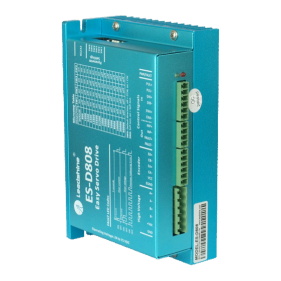
Hardware Manual of the ES-D Series Drives Introduction to the Easy Servo The ES (easy servo) series easy servos offer an alternative for applications requiring high performance and high reliability when the traditional servo was the only choice, while it remains cost-effective. The system includes an easy servo motor combined with a fully digital, high performance easy servo drive. - Page 6 Hardware Manual of the ES-D Series Drives Drive Appearance and Connector Location ES-D508 RS232 Communication Connector (RJ11) 2-bit DIP Switch (SW1: Direction, SW2: Self-test) Indicator (Green LED: Power, Red LED: Fault) Control signals connectors including digital inputs and digital outputs (Screw Terminal Blocks) Encoder feedback signals connector (HDD15)
- Page 7 Hardware Manual of the ES-D Series Drives Drive Appearance and Connector Location (Continued) ES-D808 / ES-D1008 RS232 Communication Connector (RJ11) 6-bit DIP Switch (SW1-4: Micro Step, SW5: Direction, SW6: Self-test) Indicator (Green LED: Power, Red LED: Fault) Control signals connectors including digital inputs and digital outputs (Screw Terminal Block) Encoder feedback signals connector...
-
Page 8: Wiring Diagrams
Hardware Manual of the ES-D Series Drives Wiring Diagrams RS232 Cable USB-232 Converter Motion Controller Encoder Cable * (must be used) Power Supply Power Extension Cable Wiring diagram of the ES-D508 and ES-M3 series motors Wiring diagram of the ES-D808 / ES-D1008 and ES-M2 series motors... -
Page 9: Connecting Power Supply
Hardware Manual of the ES-D Series Drives Connecting Power Supply ES-D508 and ES-D808 The ES-D508 and ES-D808 only accept DC power input. The power supply connections include only one positive terminal and one negative terminal. However you need to pay attention to terminal polarity. -
Page 10: Connecting Motor
ES-D808 / ES-D808. One end of this power extension cable includes four flying wires. You can connect these wires to the drive’s corresponding terminals as follows. ES-M22430 ES-D808 / ES-D1008 ES-M23440 ES-M23480 Power Cable Black Power Extension Cable Yellow/ Green Blue Power & Motor Connector Connect Leadshine ES-M2 series motors to ES-D808 / ES-D1008... -
Page 11: Connecting Encoder
Hardware Manual of the ES-D Series Drives Connecting Encoder As the easy servo drive works in close-loop mode, it needs to know the actual motor position. The encoder mounted on the motor offers such information. Please note that the easy servo drive can not work without encoder feedback. -
Page 12: Connecting Control Signal
Hardware Manual of the ES-D Series Drives Connecting Control Signal Pulse, Direction, Enable Input Connections The ES-D series drives can accept differential, PNP(sourcing) and NPN(sinking) pulse, direction and enable control signals. For the enable signal, apply 0V between ENA+ and ENA- or leave them unconnected to enable the drive. -
Page 13: Fault, In-Position Output Connections
Hardware Manual of the ES-D Series Drives Pulse, Direction, Enable Input Connections (Continued) Controller ES-D Drive PUL+ Step PUL- DIR+ Direction DIR- ENA+ Enable ENA- Control Signal Connector Connect the ES-D drives to differential type controllers Fault, In-position Output Connections The outputs are isolated and you can take them as electronic switch. -
Page 14: Connecting Pc
ProTuner. The ProTuner can be downloaded from our website: http://www.leadshine.com or you may also get it from our CD. It is recommended to get it from the website because software from the website is always the latest. -
Page 15: Typical Connections
Hardware Manual of the ES-D Series Drives Typical Connections Encoder Signal Controller ES-D508 Connector ES-M32309 ES-M32320 Encoder Encoder PUL+ Extension Cable* Cable PUL- *must be used DIR+ Step Power DIR- Cable Direction ENA+ ENA- Power Enable Extension Cable* Control Signal Blue Connector Black... -
Page 16: Wiring Notes
Hardware Manual of the ES-D Series Drives Typical Connections (Continued) Encoder Signal Controller ES-D1008 Connector ES-M23440 Control Signal ES-M23480 Encoder Encoder Connector Extension Cable* Cable PUL+ 5-24V 5V recommended PUL- *must be used DIR+ Step EA+: BLK EA-: BLU Power EB+: YEL EB-: GRN DIR-... -
Page 17: Configuration
Hardware Manual of the ES-D Series Drives Configuration When the default settings of the easy servo drive are not suitable for your application, it is necessary to configure the drive via the DIP switch or ProTuner (the setup software). Otherwise you may encounter problems like high motor heating, big motor noise or even motor stall due to weak torque. -
Page 18: Configuring Es Drive By The Dip Switches
Hardware Manual of the ES-D Series Drives Configuring ES drive by the DIP Switches ES-D508 There is a 2-bit DIP switch on the ES-D508 which can be used to reverse the default motion direction and perform motor self-test. Set SW2 on to activate the motor self-test. -
Page 19: Configuring Es Drive In The Pc Software
Hardware Manual of the ES-D Series Drives ES-D808 / ES-D1008 Resolution Settings (Continued) 25600 51200 1000 2000 4000 5000 8000 10000 20000 40000 Configuring ES drive in the PC Software Consult the “Connecting to PC Software” chapter for how to connect the easy servo drive to PC. Suppose the tuning software has been open, click the “Drive->Parameters”... -
Page 20: Rotating The Motor
Hardware Manual of the ES-D Series Drives Rotating the Motor Calculating Rotation Speed and Angle You may also want to calculate the motor rotation speed and rotation angle, before commanding any motion. If the pulse frequency and counts are known, they can be calculated as follows: Rotation Speed (RPM) = 60 * Pulse (Step) Frequency / Micro Step Resolution Rotation Angle (°) = 360 * Pulse (Step) Counts / Micro Step Resolution... -
Page 21: Power Supply Selection
Hardware Manual of the ES-D Series Drives Click Drive Settings->Current Loop / Motion Test to open the test window. Then click the Motion Test tab to open the emulating controller. Edit the trapezoidal velocity profile and click the Start button to execute the motion. Power Supply Selection To achieve good driving performances, it is important to choose a suitable supply voltage and use a matching current value. -
Page 22: Multiple Drives
Drive Upper Input Limit + 10% Minimum Safe Rating Drive Lower Input Limit Drive Input Voltage Power Supply Voltage Recommended Supply Voltage Both Leadshine’s regulated and unregulated power supplies are specially designed for motion control. Motor Drive Voltage Range Typical Voltage... -
Page 23: Control Signal Setup Timing
>50ms Current Control Detail Leadshine’s easy servo motor is integrated with a high-resolution 1,000-line optical incremental encoder. That encoder can send the real-time shaft position back to the ES-D drive. Like traditional servo controls, the drive can automatically adjust the output current to the motor. The output current ranges between the holding current and the close-loop current. -
Page 24: Fine Tuning
However, if you want to fine tune the ES for best performance for your applications, Leadshine also offers tuning software, ProTuner, which allows you to adjust those current-loop and position-loop parameters (see software manual). -
Page 25: Position Following Error Protection
Hardware Manual of the ES-D Series Drives Position Following Error Protection When the position error exceeds the limit (software configurable, see software manual), position, protection will be activated and red LED will blink seven times within each periodic time. Frequently Asked Questions In the event that your drive doesn’t operate properly, the first step is to identify whether the problem is electrical or mechanical in nature. -
Page 26: Warranty
Leadshine Technology Co., Ltd. warrants its products against defects in materials and workmanship for a period of 12 months from shipment out of factory. During the warranty period, Leadshine will either, at its option, repair or replace products which proved to be defective. -
Page 27: Contact Us
Web: http://www.leadshine.com Sales Hot Line: Tel: 86-755-2641-7674 (for Asia, Australia, Africa areas) 86-755-2640-9254 (for Europe areas) 86-755-2641-7617 (for America areas) Fax: 86-755-2640-2718 Email: sales@leadshine.com. Technical Support: Tel: 86-755-2641-8447, 86-755-2641-8774, 86-755-2641-0546 Fax: 86-755-2640-2718 Email: tech@leadshine.com(for All) Leadshine U.S.A Address: 25 Mauchly, Suite 318 Irvine, California 92618...
Need help?
Do you have a question about the ES Series and is the answer not in the manual?
Questions and answers