Table of Contents
Advertisement
Quick Links
Advertisement
Table of Contents

Related Manuals for Leadshine ELD2-CAN Series


Summary of Contents for Leadshine ELD2-CAN Series
- Page 1 ELD2-CAN Series DC Servo Drive User Manual...
- Page 2 User Manual of ELD2-CAN DC Servo Foreword Thank you for purchasing Leadshine ELD2-CAN series DC Servo drives. This manual will provide information on the ELD2-CAN series servo products regarding product safety & specifications, installations & wiring, tuning & problem diagnostics.
- Page 3 User Manual of ELD2-CAN DC Servo Transportation Caution Caution Please provide storage and transportation under protected conditions. Do not stack the products too high up to prevent toppling. The product should be packaged properly during transportation, Do not hold the product by the cable, motor shaft or encoder while transporting it. ...
- Page 4 User Manual of ELD2-CAN DC Servo Tuning and running Caution Caution Make sure the wirings of servo drive and servo motor are installed and fixed properly before powering on. On the first time tuning of the product, it is recommended to run unloaded until all the parameter settings are confirmed to prevent any damage to the product or machine.
- Page 5 If available, please send product back in original packaging or make sure it is well packaged to prevent any damage to the product during shipping. Leadshine Technology Co.,Ltd. and its certified sales channel reserved the final right of the interpretation of the warranty information.
-
Page 6: Table Of Contents
User Manual of ELD2-CAN DC Servo TABLE OF CONTENT CHAPTER 1 INTRODUCTION ........................... 9 ..........................9 RODUCT NTRODUCTION 1.2 M ........................... 10 ODEL UMBER TRUCTURE 1.2.1 Servo Drive ..............................10 1.2.2 Servo Motor ............................... 10 1.3 S ........................11 ERVO RIVE ECHNICAL PECIFICATION... - Page 7 User Manual of ELD2-CAN DC Servo 3.2.3 Class 2 Vibration Suppression ......................56 【 】 3.2.4 Class 3 Velocity/ Torque Control ......................61 【 】 3.2.5 Class 4 I/O Interface Setting ......................... 63 【 】 3.2.6 Class 5 Extension settings ........................69 【...
- Page 8 User Manual of ELD2-CAN DC Servo CHAPTER 6 CANOPEN COMMUNICATION ......................139 6.1 C ..........................139 OMMUNICATION CONNECTION 6.2 CAN ....................139 OPEN COMMUNICATION PARAMETERS AND PORTS 6.3 CAN ........................141 OPEN COMMUNICATION PROTOCOL 6.4 P ............................ 141 REDEFINED ONNECTIONS 6.5 O .............................
-
Page 9: Chapter 1 Introduction
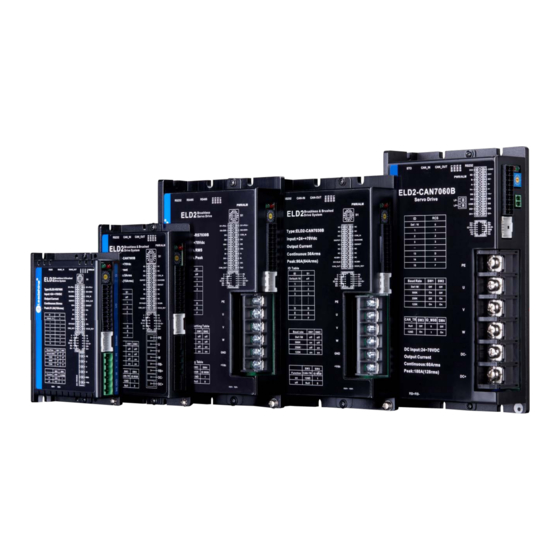
Chapter 1 Introduction 1.1 Product Introduction ELD2-CAN Series DC Servo Drive is our latest generation DC servo drive that is based on CANopen DSP402 protocol. It can be easily matched to any controller that supports this protocol. Using the latest signal processing chip from Texas Instrument, the drive is compact with small volume and good reliability. -
Page 10: Model Number Structure
User Manual of ELD2-CAN DC Servo 1.2 Model Number Structure 1.2.1 Servo Drive ELD2 - CAN 7030 B ○ ○ ○ ○ ① Description Series No. ELD2: DC Servo Drive Series ② RS:Pulse train + Modbus RTU Communication protocol CAN:CANopen + Analogue ③... -
Page 11: Servo Drive Technical Specification
User Manual of ELD2-CAN DC Servo 1.3 Servo Drive Technical Specification ELD2-CAN series CAN7005B CAN7010B CAN7015B CAN7020B CAN7030B Rated Current (Arms) Peak Current (Arms) Dimension(mm) 140*79.5*25.5 175*100.5*33 ELD2-CAN series CAN7040B CAN7060B Rated Current (Arms) Peak Current (Arms) Dimension(mm) 194*103*41 Logic Power Supply... -
Page 12: Servo Drive Ports And Connectors
Storage -20℃~+65℃ temperature 40—90%RH (Condensation free) Humidity Installation Vertical and level to ground 1.4 Servo Drive Ports and Connectors ELD2-CAN Series Servo Drive (7005B/7010B/7015B/7020B/7030B) CANopen Baud Rate/Terminal Communication Port Resistor Switch RS232 Tuning Port Indicator LED (PWR/ALM) ID Spin Dial (RSC-1) -
Page 13: Motor Ports And Connectors
User Manual of ELD2-CAN DC Servo ELD2-CAN Series Servo Drive (7040B/7060B) CANopen Baud Rate/Terminal Communication Port Resistor Switch Safe Torque Off (STO) RS232 Tuning Port Indicator LED (PWR/ALM) ID Spin Dial (RSC-1) I/O Port (CN1) Logic Circuit Power Supply ENC Encoder Port... -
Page 14: Chapter 2 Installation & Wiring
User Manual of ELD2-CAN DC Servo Chapter 2 Installation & Wiring 2.1 Servo Drive Installation 2.1.1 Servo drive installation environment Storage: -20~+65℃ (Condensation free); Temperature Installation: -20~+45℃ ( Please allow air circulation if >45℃) Humidity Under 90%RH (Condensation free) Altitude Up to 1000m above sea level Atmospheric 86 ~ 106kPa... - Page 15 User Manual of ELD2-CAN DC Servo Dimension 2: ELD2-CAN7015B/7020B/7030B Dimension 3: ELD2-CAN7040B/7060B...
- Page 16 User Manual of ELD2-CAN DC Servo Space requirement for installation 1. Please install the drive vertical to ground. 2. Please ensure optimal heat dissipation with enough room (>50mm) between each drives or to surrounding. It is recommended to install cooling fans for drives to achieve optimal performance. Please allow a gap larger than 50mm between drives and surrounding Please refer to the diagram above for a visual guide on how to properly install the DC servo...
-
Page 17: Servo Motor Installation
User Manual of ELD2-CAN DC Servo 2.2 Servo Motor Installation 2.2.1 Installation conditions Installation conditions may affect the lifespan of a motor Please keep away from corrosive fluid and combustibles. If dusty working environment is unavoidable, please use motors with oil seal. ... -
Page 18: Eld2-Can Wiring Diagram
User Manual of ELD2-CAN DC Servo 2.3 ELD2-CAN Wiring Diagram ELD2-CAN Wiring Diagram Make sure data transferring cables are as short as possible. Keep CN1 cable under 3m and CN2 cable under 10m. Use shielded double winding cables to cut down on electromagnetic interference. -
Page 19: Servo Drive Ports
User Manual of ELD2-CAN DC Servo 2.4 Servo Drive Ports ELD2-CAN 7005B/7010B/7015B/7020B/7030B CN5 CANopen Communication Port Baud Rate/Terminal Resistor Switch CN7 RS232 Tuning Port Indicator LED (PWR/ALM) ID Spin Dial (RSC-1) I/O Port (CN1) ENC Encoder Port CN3 Motor Power Output (U, V, W, PE) CN3 Main Power Supply (DC+, GND) - Page 20 User Manual of ELD2-CAN DC Servo ELD2-CAN 7040B/7060B CN5 CANopen Communication Port Baud Rate/Terminal Resistor Switch CN6 Safe Torque Off CN7 RS232 Tuning (STO) Port Indicator LED (PWR/ALM) ID Spin Dial (RSC-1) CN9 Logic Circuit Power I/O Port (CN1) Supply ENC Encoder Port CN3 Motor Power Output (U, V, W, PE)
-
Page 21: Cn1 I/O Signal Port
User Manual of ELD2-CAN DC Servo 2.4.1 CN1 I/O Signal Port Diagram Signal Description COM_IN Common DI Emergency stop Homing switch Positive limit Negative limit Encoder signal A output Encoder signal B output Holding brake output positive and negative terminal, max current output: 1A Alarm output, current output <100mA Servo ready, current output <100mA COM_OUT... -
Page 22: Cn3/Cn4 Power Supply & Regenerative Resistor Port
User Manual of ELD2-CAN DC Servo CN1 control signal cable selection To ensure I/O signal to not be affected by electromagnetic interference, a shielded cable is recommended for this application. Foil shield Cables for different analogue signals should be using isolated shielded cable while cables for digital signals should be shielded twisted pair cable. -
Page 23: Cn6 Safe Torque Off (Sto) Port
User Manual of ELD2-CAN DC Servo 2.4.4 CN6 Safe Torque Off (STO) Port Port Diagram Signal Description Remarks 24v power supply Connect to SF1 and SF2 when not in use. Do not Reference ground use to supply power. STO 1 positive input STO1+ STO 1 negative input STO1-... -
Page 24: Cn7 Rs232 Tuning Port
It is recommended to use an isolated power supply for STO signal input as any current leakage might cause STO malfunction. 2.4.5 CN7 RS232 Tuning Port Port Diagram Signal ELD2-CAN Series DC Servo Drive can be connected to Motion Studio 2 for parameters tuning and data monitoring using CABLE-PC-1. -
Page 25: Cn9 Logic Circuit Power Supply Port
User Manual of ELD2-CAN DC Servo 2.4.6 CN9 Logic Circuit Power Supply Port Port Diagram Signal Description 24V positive terminal 24V negative terminal ELD2-CAN7040B/7060B dual-axis DC servo drives include an optional logic circuit power supply port. When main power supply is cut, logic circuit power supply port can be connected to realize: 1. -
Page 26: Id Spin Dial Rsc
User Manual of ELD2-CAN DC Servo Note: Molex 55959-1230 Connector Header (Driver side) Molex 51353-1200 12-pin rectangle connector 1pcs for each axis (Provided) Molex 56134-9000 female terminal reel 12pcs for each axis (Provided) 2.4.8 ID spin dial RSC Diagram CAN address CAN address... -
Page 27: Cable Selection
Wire length available: 0.5m, 1.5m, 3m, 5m, 7m and 10m. Connectors type available: SP21 connector Please contact Leadshine sales team or any Leadshine certified local retailers for any customized needs. *M*: Length of the cable Motor Power Cable CABLE-RZD*M*-263 12AWG... - Page 28 User Manual of ELD2-CAN DC Servo Motor Power Cable CABLE-RZD*M*-143 16AWG Motor side Driver side Driver cable pin Pins Motor Color Driver White Black Yellow- green Motor Power Cable CABLE-RZD*M*-123 18AWG Motor side Driver side Driver cable pin Pins Motor Color Driver White...
- Page 29 User Manual of ELD2-CAN DC Servo Motor Power Cable CABLE-RZD*M*-282 – 130 Frame Motor without brake Motor side Driver side Motor cable pin Pins Motor Color Driver White Black Yellow- green Motor Power Cable CABLE-RSZD*M*-282 – 130 Frame Motor with brake Motor side Driver side Motor cable pin...
-
Page 30: Motor Encoder Cable
User Manual of ELD2-CAN DC Servo • Grounding: Grounding wire should be thicker. Ground PE terminal of servo drive and servo motor together with resistance <100 Ω. • Connect a line filter to power supply to reduce electromagnetic interference. • Please install a fuseless circuit breaker to cut off power supply in time when the driver fails. -
Page 31: Motor Brake Cable
User Manual of ELD2-CAN DC Servo For ELVM series motors with 130 flange size CABLE-BMD*M*-212 for single turn encoder Motor side Driver side Motor cable pin Color Signal Motor Drive Braid Shield Red- white Blue Blue- Black Motor side Driver side CABLE-BMAD*M*-222 with battery kit for multiturn absolute encoder Motor side Driver side... -
Page 32: Drive Communication Cable
User Manual of ELD2-CAN DC Servo 2.5.3 Motor Brake Cable CABLE-SCD*M*-113 Motor side Driver side - 22AWG cables *Note: Black – 0V, Red – 24V 2.5.4 Drive Communication Cable CABLE-TX*M*-LD2 - For CANopen and Modbus RS485 communication between drives/controller. 2.5.5 Tuning Cable CABLE-PC-1 - To connect to Motion Studio 2 PC tuning software. -
Page 33: Regenerative Resistor Selection
User Manual of ELD2-CAN DC Servo 2.6 Regenerative Resistor Selection The use of regenerative resistor When the motor opposes the direction of rotation as in deceleration or vertical axis escalation, part of the regenerative energy will be delivered back to the driver. This energy will first be stored in internal capacitors of the driver. - Page 34 User Manual of ELD2-CAN DC Servo Theoretical selection of regenerative resistor Without external loading torque, the need for an external regenerative resistor can be determined as the flow chart below Start T is the time for velocity to reach Determine the max.
- Page 35 User Manual of ELD2-CAN DC Servo Diagram below shows the acceleration and deceleration cycle periods and the regenerative torque that occurs during the process. V:Motor rotational velocity Rotational velocity :Deceleration time Motor Torque : Load torque Regenerative torque Steps to calculate capacity of regenerative resistor Steps Calculation Symbol...
- Page 36 User Manual of ELD2-CAN DC Servo Internal capacitor capacity and rotor inertia Rotor Inertia Max. regenerative energy ELD2 Drives Servo motor (× 10 kg.m stored in capacitor Ec(J) ) 750W (7020B) ELVM8075V48FH-M17 2.26 1000W (7030B) ELVM80100V48FH-M17 1.79 2.26 There are motors with low, medium and high inertia. Different motor models have different rotor inertia. Please refer to product catalogue for more information on rotor inertia.
-
Page 37: Chapter 3 Parameter
User Manual of ELD2-CAN DC Servo Chapter 3 Parameter 3.1 Parameter List Panel Display as follows: Parameter Valid mode Description HM: Valid in homing mode PP: Valid in profile position mode PV: Valid in profile velocity mode PT: Valid in profile torque mode F: Valid in all modes 3.1.1 Servo drive parameter CANopen... - Page 38 User Manual of ELD2-CAN DC Servo CANopen Label Class Parameter Activation Valid Mode Address velocity detection filter 2103h PR_103 Immediate Torque Filter Time 2104h PR_104 Immediate Constant Position Loop Gain 2105h PR_105 Immediate velocity loop gain 2106h PR_106 Immediate Integral Time 2107h PR_107 Immediate...
- Page 39 User Manual of ELD2-CAN DC Servo CANopen Label Class Parameter Activation Valid Mode Address notch depth selection 2209h PR_209 Immediate damping frequency 2214h PR_214 Immediate filter 2215h PR_215 Immediate Position command Keep stop 2222h PR_222 smoothing filter Position command FIR 2223h PR_223 Disable...
- Page 40 User Manual of ELD2-CAN DC Servo CANopen Label Class Parameter Activation Valid Mode Address Input selection DI4 2403h PR_403 Immediate Output selection DO1 2410h PR_410 Immediate Output selection DO2 2411h PR_411 Immediate Output selection DO3 2412h PR_412 Immediate Positioning complete 2431h PR_431 Immediate...
- Page 41 User Manual of ELD2-CAN DC Servo CANopen Label Class Parameter Activation Valid Mode Address additional value Positive direction torque 2608h PR_608 Immediate compensation value Negative direction torque 2609h PR_609 Immediate compensation value Current response 2611h PR_611 Immediate settings Encoder zero position 2612h PR_612...
- Page 42 User Manual of ELD2-CAN DC Servo CANopen Label Class Parameter Activation Valid Mode Address Motor rated rotational Immediate speed 2710h PR_710 Motor maximum speed 2711h PR_711 Immediate Motor rated current 2712h PR_712 Immediate Motor rotor inertia 2713h PR_713 Immediate Motor power rating 2714h PR_714 Immediate...
-
Page 43: Motion Parameter Starting With Object Dictionary 6000
User Manual of ELD2-CAN DC Servo 3.1.2 Motion parameter starting with object dictionary 6000 Index Sub-index Label Unit Default Mode Error code 0xFFFF 603F Control word 0xFFFF 6040 Status word 0xFFFF 6041 605A Quick stop option code Shutdown option code 605B Disable operation... - Page 44 User Manual of ELD2-CAN DC Servo Command 2147483 Max. software limit 2147483 unit Polarity 607E 0xFF Command 214748 2147483 PP/HM Max Profile Velocity 607F unit /s 3647 2147483 Max Motor Speed 6080 r/min 6000 Command 2147483 Profile Velocity 10000 6081 unit /s Command 2147483...
-
Page 45: Parameter Function
User Manual of ELD2-CAN DC Servo unit /s 2147483 Position Demand Internal Encoder 2147483 60FC 2147483 PP/HM Value unit 0x7FFFF Digital Inputs 60FD Number of Entries 0x7FFFF 60FE Physical Outputs 0x7FFFF Bit Mask Command 2147483 60FF Target velocity 2147483 unit /s 0x7FFFF 6502 Supported drive modes... - Page 46 User Manual of ELD2-CAN DC Servo Label Control Mode Settings Valid Mode Pr0.01 Range Unit — Default Index 2001h Activation After restart Set value to use following control modes: Value Content Details Only for internal position Position Only for internal velocity Velocity Reserved PP/PV/PT/HM...
- Page 47 User Manual of ELD2-CAN DC Servo Label Inertia ratio Mode Pr0.04 Range 0~20000 Unit Default Index 2004h Activation Immediate Pr0.04=( load inertia/motor rotational inertia)×100% Notice: Set inertia ratio according to actual load inertia. When both are uniform, actual motor velocity loop responsiveness and gain settings will be consistent.
- Page 48 User Manual of ELD2-CAN DC Servo Label Absolute Encoder settings Mode Pr0.15 Range 0~32767 Unit Default Index 2015h Activation Immediate 0: Incremental mode: Used as an incremental encoder. Doesn’t retain position data on power off. Unlimited travel distance. 1: Multiturn linear mode: Used as a multiturn absolute encoder.
-
Page 49: Class 1】Gain Adjustments
User Manual of ELD2-CAN DC Servo Label CAN Baud rate Mode Pr0.24 Range 0~10 Unit — Default Index 2024h Activation After restart CANopen device Baud rate settings Pr0.24 CAN Baud rate(kHz) Pr0.24 CAN Baud rate(kHz) 1000 3.2.2【Class 1】Gain Adjustments Label position loop gain Mode 0~3000... - Page 50 User Manual of ELD2-CAN DC Servo Label velocity detection filter Mode Range 0~10000 Unit — Default Index 2103h Pr1.03 Activation Immediate This filter is a low pass filter. It blocks high frequencies which cause system instability from velocity feedback data. The higher the set value, lower frequencies will be blocked and velocity responsiveness will also be lowered.
- Page 51 User Manual of ELD2-CAN DC Servo Label Position Loop Gain Mode Range 0~30000 Unit 0.1/s Default Index 2105h Pr1.05 Activation Immediate Label velocity loop gain Mode Range 1~32767 Unit 0.1Hz Default Index 2106h Pr1.06 Activation Immediate Integral Time Constant of Velocity Label Mode Loop...
- Page 52 User Manual of ELD2-CAN DC Servo Set velocity feed forward low pass filter to eliminate high or abnormal frequencies in velocity feed forward command. Often used when position command with low resolution or high electronic gear ration to smoothen velocity feed forward. Position deviation under constant velocity can be lowered with higher velocity feed forward gain.
- Page 53 User Manual of ELD2-CAN DC Servo Position control gain Label Mode switching mode Pr1.15 Range 0~11 Unit — Default Index 2115h Activation Immediate Condition Gain switching condition Value gain fixed Fixed on using 1 gain(Pr1.00-Pr1.04) gain fixed Fixed on using 2 gain (Pr1.05-Pr1.09) Reserved Switch to 2...
- Page 54 User Manual of ELD2-CAN DC Servo Valid for position control. Switch to 2 gain when position deviation absolute value larger than (level + hysteresis)[pulse] Switch to 1 gain when position deviation absolute value smaller than (level-hysteresis)[pulse] Large position deviation Velocity Level Hysteresis Position...
- Page 55 User Manual of ELD2-CAN DC Servo Hysteresis Level Velocity Feedback Valid for position control. Switch to 2 gain if position command ≠ 0 Switch to 1 gain if positional command = 0 throughout the duration of delay time and absolute value of actual velocity remains smaller than (level - hysteresis) (r/min) Pending position command...
-
Page 56: Class 2】Vibration Suppression
User Manual of ELD2-CAN DC Servo Hysteresis at position Label Mode control switching Mode Pr1.18 Range 0~20000 Unit Default Index 2118h dependent Activation Immediate To eliminate the instability of gain switching. Used in combination with Pr1.17 using the same unit. If level<... - Page 57 User Manual of ELD2-CAN DC Servo Label notch frequency Mode Range 50~4000 Unit Hz Default 4000 Index 2201h Pr2.01 Activation Immediate Set center frequency of 1 torque command notch filter. Set Pr2.01 to 4000 to deactivate notch filter notch bandwidth Label Mode selection...
- Page 58 User Manual of ELD2-CAN DC Servo Label notch depth selection Mode Range 0~99 Unit Default Index 2206h Pr2.06 Activation Immediate Set notch depth for 1 resonant notch filter. When Pr2.06 value is higher, notch depth becomes shallow, phase lag reduces. Under normal circumstances, please use factory default settings.
- Page 59 User Manual of ELD2-CAN DC Servo Position command Label Mode smoothing filter Pr2.22 Range 0~32767 Unit 0.1ms Default Index 2222h Activation Stop axis To set time constant of 1 time delay filter of position command. To set time constant of 1 time delay filter, according to target velocity Vc square wave command as show below.
- Page 60 User Manual of ELD2-CAN DC Servo Position command Label Mode filter Pr2.23 Range 0~10000 Unit 0.1ms Default Index 2223h Activation Disable axis As shown below, when target velocity Vc square wave command reaches Vc, it becomes trapezoidal wave after filtering. Position Position command Velocity...
-
Page 61: Class 3】Velocity/ Torque Control
User Manual of ELD2-CAN DC Servo 3.2.4【Class 3】Velocity/ Torque Control Internal/External settings Label Mode of velocity settings Pr3.00 Range Unit Default Index 2300h Activation Immediate Internal settings can be achieved by connecting to driver’s input interface. velocity Set value Velocity settings Analog velocity command (SPR) Internal velocity command: 1 to 4... - Page 62 User Manual of ELD2-CAN DC Servo Label Mode speed of velocity setting Range -10000~10000 Unit r/min Default Index 2308h Pr3.08 Activation Immediate Label Mode speed of velocity setting Range -10000~10000 Unit r/min Default Index 2309h Pr3.09 Activation Immediate Label Mode speed of velocity setting Range -10000~10000...
-
Page 63: Class 4】I/O Interface Setting
User Manual of ELD2-CAN DC Servo Sigmoid Label acceleration/deceleration Mode settings Pr3.14 Range 0~1000 Unit Default Index 2314h Activation Axis disable To set sigmoid acceleration and deceleration turning point in accordance to Pr3.12 and Pr3.13. Velocity (RPM) Target velocity ta=Vc/1000 PA3.12 1ms td=Vc/1000 PA3.13 1ms ts=Pr3.14 1ms Please set according to... - Page 64 User Manual of ELD2-CAN DC Servo Label Input selection DI4 Mode Range 0x0~0xFF Unit — Default Index 0x16 2403h Pr4.03 Activation Immediate Digital input DI allocation using hexadecimal system Set value Input Symbol Normally Normally 0x60FD (bit) open close Invalid —...
- Page 65 User Manual of ELD2-CAN DC Servo Velocity coincidence V-COIN Servo status SRV-ST Position command ON/OFF P-CMD Velocity limit signal V-LIMIT Velocity command ON/OFF V-CMD Homing done HOME-OK · Please don’t set any other than the outputs listed in the table above. ·...
- Page 66 User Manual of ELD2-CAN DC Servo positioning delay Label Mode time Pr4.33 Range 0~15000 Unit Default Index 2433h Activation Immediate To set delay time when Pr 4.32 = 3 Set value Positioning completed signal Indefinite delay time, signal ON until next position command OFF within the time set;...
- Page 67 User Manual of ELD2-CAN DC Servo Velocity coincidence Label Mode range Pr4.35 Range 10~2000 Unit Default Index 2435h Activation Immediate If the difference between velocity command and motor actual speed is below Pr4.35, Velocity coincidence (V-COIN) output signal valid. Due to 10RPM hysteresis: Velocity coincidence output OFF ->...
- Page 68 User Manual of ELD2-CAN DC Servo Label Mode Motor power-off delay time Range 0~3000 Unit Default Index 2437h Pr4.37 Activation Immediate To set delay time for holding brake to be activated after motor power off to prevent axis from sliding. Delay time for holding brake Label Mode...
-
Page 69: Class 5】Extension Settings
User Manual of ELD2-CAN DC Servo Label Holding brake activation speed Mode Range 30~3000 Unit Default Index 2439h Pr4.39 Activation Immediate To set the activation speed for which holding brake will be activated. When SRV-OFF signal is given, motor decelerates, after it reaches below Pr4.39 and Pr6.14 is not yet reached, BRK_OFF is given. - Page 70 User Manual of ELD2-CAN DC Servo To set servo driver disable mode and status. Explanation Set value Mode Status Servo braking Dynamic braking Free stopping Dynamic braking Dynamic braking Dynamic braking Servo braking Free-run Free stopping Free-run Dynamic braking Free-run Label Main power-off detection time Mode...
- Page 71 User Manual of ELD2-CAN DC Servo To set torque limit for servo braking mode. If Pr5.11 = 0, use torque limit as under normal situation. Between max. torque 6072 and Pr5.11, actual torque limit will take smaller value. Overload level Label Mode setting...
- Page 72 User Manual of ELD2-CAN DC Servo Label Torque limit selection Mode Range Unit — Default Index 2521h Pr5.21 Activation Immediate Set value Positive limit Negative limit value value Pr0.13 Pr0.13 Pr0.13 Pr5.22 60E0 60E1 Between max. torque 6072 and Pr5.21, actual torque limit will take smaller value. Label torque limit Mode...
-
Page 73: Class 6 】 Other Settings
User Manual of ELD2-CAN DC Servo 3.2.7【Class 6】Other settings trial velocity Label Mode command Pr6.04 Range 0~10000 Unit r/min Default Index 2604h Activation Immediate To set velocity for JOG trial run command. Label Position 3 gain valid time Mode Range 0~10000 Unit 0.1ms Default... - Page 74 User Manual of ELD2-CAN DC Servo Label Torque command additional Mode value Range -100~100 Unit Default Index 2607h Pr6.07 Activation Immediate To set torque forward feed additional value of vertical axis. Applicable for loaded vertical axis, compensate constant torque. Application: When load move along vertical axis, pick any point from the whole motion and stop the load at that particular point with motor enabled but not rotating.
- Page 75 User Manual of ELD2-CAN DC Servo BRK_ON given time is determined by Pr6.14 or when motor speed goes below Pr4.39, whichever comes first. Applications: 1. After disabling axis, if motor speed is still higher than Pr4.39 but the time set in Pr6.14 is reached, BRK_ON given and holding brake activated.
- Page 76 User Manual of ELD2-CAN DC Servo To set delay time for blocked rotor alarm to trigger Label Homing position (16-bit high) Mode -2147483647~ Range Unit Default Index 2658h Pr6.58 2147483647 Activation Immediate Homing position 16-bit high Homing position (16-bit Label Mode low) -2147483647~...
-
Page 77: Parameters Function
User Manual of ELD2-CAN DC Servo 3.3 402 Parameters Function Panel Display as follows: Parameter Valid mode Description HM: Valid in homing mode PP: Valid in profile position mode PV: Valid in profile velocity mode PT: Valid in profile torque mode F: Valid in all modes Label Error code... - Page 78 User Manual of ELD2-CAN DC Servo Label Status word Unit Structure Type Uint 16 Index 0x0~ 6041h Access Mapping TPDO Mode Range 0xFF Default Label Description Servo ready 1 - valid, 0 - invalid Start 1 - valid, 0 - invalid Servo running 1 - valid, 0 - invalid Fault...
- Page 79 User Manual of ELD2-CAN DC Servo Label Shutdown option code Mode Index 605Bh Range Unit Range Default PP, PV 0 :To stop motor through Pr5.06, 5.06 = 0(Emergency stop), 5.06=1(Free stop) 1 :Motor decelerates and stops through 6084 0 :To stop motor through Pr5.06, 5.06 = 0(Emergency stop), 5.06=1(Free stop) 1 :Motor decelerates and stops through 609A Label Disable operation option code...
- Page 80 User Manual of ELD2-CAN DC Servo Label Mode of Operation Unit Structure Type Int 8 Index 6060h Access Mapping RPDO Mode Range -2~6 Default Mode Abbr. Profile position mode Profile velocity mode profile Torque mode Homing mode Mode Operation Label Unit Structure Type...
- Page 81 User Manual of ELD2-CAN DC Servo Position Actual Comman Label Unit Structure Type Int 32 Value d unit Index 6064h 214748364 Access Mapping TPDO Mode Range Default 8~2147483 Reflects user’s real time absolute position 6064h*Gear ratio = 6063h Velocity Demand Comman Label Unit...
- Page 82 User Manual of ELD2-CAN DC Servo Label Torque Demand Unit 0.1% Structure Type Int 16 Index 6074h Access Mapping TPDO Mode Range 32768~3 Default 2767 Internal command torque Label Motor Rated Current Unit Structure Type Int 32 Index 0~21474 6075h Access Mapping TPDO...
- Page 83 User Manual of ELD2-CAN DC Servo Homing position Command Label Unit Structure Type offset unit Index 607Ch 214748364 Access TPDO Mode Range Default Mapping 7~2147483 To set position offset to compensate for the deviation of mechanical origin from motor origin under homing Command Label...
- Page 84 User Manual of ELD2-CAN DC Servo Command Label Max Profile Velocity Unit Structure Type UInt 32 unit/s Index 0~214 607Fh PP/HM/P 21474836 Access Mapping RPDO Mode Range 74836 Default To set maximum allowable velocity. Limited by 6080. Label Max Motor Speed Unit R/min Structure...
- Page 85 User Manual of ELD2-CAN DC Servo Label Encoder Increments Unit Encoder unit Structure Type UInt 32 Index 1~2147 608Fh-01 Access TPDO Mode Range 48364 Default Mapping To set encoder resolution Label Motor Revolutions Unit Structure VAR Type Dint 32 Index 6091h-01 Access Mapping...
- Page 86 User Manual of ELD2-CAN DC Servo homing switch Negative Homing switch Motor Z-signal Rising edge on same side of homing switch Positive Homing switch Motor Z-signal Falling edge on same side of homing switch Positive Homing switch Motor Z-signal Rising edge on same side of homing switch Positive Homing switch...
- Page 87 User Manual of ELD2-CAN DC Servo Comman Label Max Acceleration Unit Structure Type UInt 32 Index d unit/s² 60C5h 1~21474836 1000000 Access Mapping RPDO Mode Range Default To set upper limit of acceleration. Command Label Max Deceleration Unit Structure Type UInt 32 unit/s²...
- Page 88 User Manual of ELD2-CAN DC Servo Label Digital Inputs Unit Structure Type UINT 32 Index CSP/PP/H 214748364 60FDh Access TPDO Mode Range Default Mapping 8~2147483 The bits of 60FDh object are functionally defined as follow: Bit31 Bit30 Bit29 Bit28 Bit27 Bit26 Bit25 Bit24...
-
Page 89: Chapter 4 Control Mode
User Manual of ELD2-CAN DC Servo Chapter 4 Control Mode 4.1 Profile Position Mode 4.1.1 Pulse Equivalence Pulse uses 6091H or 6092H parameters in object dictionary. Electronic gear ratio has a range of 1/1000 ~ 8000, if not Er A00 will appear. Error disappear after the parameter is set to be within the range but 402 state machine error status might still exist, please write 0x80 into control word (6040h) to deactivate the error status. -
Page 90: Monitoring Settings
User Manual of ELD2-CAN DC Servo 607Ah Target position pulse 6081h Profile velocity pulse/s 6083h Profile acceleration pulse/s 6084h Profile deceleration pulse/s 6092h Pulse count per rev 4.1.3 Monitoring settings To monitor 6041h for motion status To monitor 6064h for real time update of position during operation ... -
Page 91: Profile Velocity Mode
User Manual of ELD2-CAN DC Servo 4.2 Profile Velocity Mode 4.2.1 Motion Settings Set 6060h = 3 for Profile Velocity mode. Set target velocity to 60FFh (Unit: pulse/s) Set profile acceleration and deceleration to 6083h and 6084h (Unit: pulse/s ... -
Page 92: Profile Torque Mode
User Manual of ELD2-CAN DC Servo 4.3 Profile Torque Mode 4.3.1 Motion Settings Set 6060h = 4 for Profile Torque mode. Set torque limit to 6071h (Unit: 0.1%) Set profile torque change rate to 6087h (Unit: 0.1%/s) Set velocity limit to 6080h (Unit: rpm) ... -
Page 93: Homing Mode
User Manual of ELD2-CAN DC Servo Write Control word = 06h, machine status changes 40 60 00 06 00 00 00 Ready to Switch On-> Switched On Drive internal relay closes Note: Step 1 and step 2 frame ID = 0x0000, the rest = SDO address (0x0600+node no.) 4.4 Homing mode 4.4.1 Motion Settings Set 6060h = 6 for Homing mode. -
Page 94: Homing Mode
User Manual of ELD2-CAN DC Servo 60 60 00 06 00 00 00 Write Operation Mode = 6h, homing mode 99 60 01 30 75 00 00 Write homing high velocity = 7530h (180rpm, default 10000ppr) Write homing low velocity = 4e20h (120rpm, default 10000ppr) 99 60 02 20 4e 00 00 Write homing acceleration = 7530h (Accelerates to 180rpm in... - Page 95 User Manual of ELD2-CAN DC Servo Low velocity Start Stop 6099h-02h Mode -4:Search for homing point in negative direction at high velocity. Move in positive direction after torque reaches the value set in Pr5.39, stops when torque is gone. Homing done signal delivers after the time value set in Pr5.37 High velocity Low velocity...
- Page 96 User Manual of ELD2-CAN DC Servo Mode -2:Search for homing point in negative direction at low velocity. Move in positive direction after torque reaches the value set in Pr5.39, stops when torque is gone with the first Z-signal. High velocity Low velocity Start Stop...
- Page 97 User Manual of ELD2-CAN DC Servo Mode 1: Negative limit switch = OFF Diagram A: 1. Move in negative direction at high velocity until negative limit switch valid. 2. Move in positive direction at low velocity and stops after negative limit switch and first encoder Z-signal valid Negative limit switch = ON Diagram B:...
- Page 98 User Manual of ELD2-CAN DC Servo Mode 2: Positive limit switch = OFF Diagram A: 1. Move in positive direction at high velocity until positive limit switch valid. 2. Move in negative direction at low velocity and stops after positive limit switch and first encoder Z-signal valid Positive limit switch = ON Diagram B:...
- Page 99 User Manual of ELD2-CAN DC Servo Mode 3: Homing switch = OFF Diagram A: 1. Move in positive direction at high velocity until homing switch valid. 2. Move in negative direction at low velocity and stops after homing switch and first encoder Z- signal valid Homing switch = ON Diagram B:...
- Page 100 User Manual of ELD2-CAN DC Servo Mode 4: Homing switch = OFF Diagram A: 1. Move in positive direction at high velocity until homing switch valid. 2. Move in negative direction at high velocity until homing switch invalid. 3. Move in positive direction at low velocity and stops after homing switch valid and first encoder Z-signal valid Homing switch = ON Diagram B:...
- Page 101 User Manual of ELD2-CAN DC Servo Mode 5: Homing switch = OFF Diagram A: 1. Move in negative direction at high velocity until homing switch valid. 2. Move in positive direction at low velocity and stops after homing switch and first encoder Z- signal valid Homing switch = ON Diagram B:...
- Page 102 User Manual of ELD2-CAN DC Servo Mode 6: Homing switch = OFF Diagram A: 1. Move in negative direction at high velocity until homing switch valid. 2. Move in positive direction at high velocity until homing switch invalid. 3. Move in negative direction at low velocity and stops after homing switch valid and first encoder Z-signal valid Homing switch = ON Diagram B:...
- Page 103 User Manual of ELD2-CAN DC Servo Mode 7 Homing switch & positive limit switch = OFF Diagram A: 1. Move in positive direction at high velocity until homing switch valid. 2. Move in negative direction at low velocity and stops after homing switch and first encoder Z- signal valid.
- Page 104 User Manual of ELD2-CAN DC Servo Mode 8 Homing switch & positive limit switch = OFF Diagram A: 1. Move in positive direction at high velocity until homing switch valid. 2. Move in negative direction at high velocity until after homing switch. 3.
- Page 105 User Manual of ELD2-CAN DC Servo Mode 9 Homing switch & positive limit switch = OFF Diagram A: 1. Move in positive direction at high velocity until after homing switch. 2. Move in negative direction at low velocity and stops after homing switch valid and first encoder Z-signal valid.
- Page 106 User Manual of ELD2-CAN DC Servo Mode 10 Homing switch & positive limit switch = OFF Diagram A: 1. Move in positive direction at high velocity until after homing switch. 2. Move in negative direction at high velocity until homing switch valid. 3.
- Page 107 User Manual of ELD2-CAN DC Servo Mode 11 Homing switch & negative limit switch = OFF Diagram A: 1. Move in negative direction at high velocity until homing switch valid. 2. Move in positive direction at low velocity and stops after homing switch and first encoder Z- signal valid Homing switch = ON, negative limit switch = OFF Diagram B:...
- Page 108 User Manual of ELD2-CAN DC Servo Mode 12 Homing switch & negative limit switch = OFF Diagram A: 1. Move in negative direction at high velocity until homing switch valid. 2. Move in positive direction at high velocity until after homing switch. 3.
- Page 109 User Manual of ELD2-CAN DC Servo Mode 13 Homing switch & negative limit switch = OFF Diagram A: 1. Move in negative direction at high velocity until after homing switch. 2. Move in positive direction at low velocity and stops after homing switch valid and first encoder Z-signal valid.
- Page 110 User Manual of ELD2-CAN DC Servo Mode 14 Homing switch & negative limit switch = OFF Diagram A: 1. Move in negative direction at high velocity until after homing switch. 2. Move in positive direction at high velocity until homing switch valid. 3.
- Page 111 User Manual of ELD2-CAN DC Servo Mode 17: This mode is similar to mode 1. Only difference is that homing point detection is not through Z- signal but through triggering of negative limit switch signal Low velocity High velocity Start Stop 6099h-02h 6099h-01h...
- Page 112 User Manual of ELD2-CAN DC Servo Mode 19: This mode is similar to mode 3. Only difference is that homing point detection is not through Z- signal but through triggering of homing switch signal High velocity Low velocity Start Stop 6099h-01h 6099h-02h Z-signal...
- Page 113 User Manual of ELD2-CAN DC Servo Mode 21: This mode is similar to mode 5. Only difference is that homing point detection is not through Z- signal but through triggering of homing switch signal. High Velocity Low Velocity Start Stop 6099h-01h 6099h-02h Z-Signal...
- Page 114 User Manual of ELD2-CAN DC Servo Mode 23: This mode is similar to mode 7. Only difference is that homing point detection is not through Z- signal but through triggering of homing switch signal. High velocity Low velocity Start Stop 6099h-01h 6099h-02h Z-Signal...
- Page 115 User Manual of ELD2-CAN DC Servo Mode 25: This mode is similar to mode 9. Only difference is that homing point detection is not through Z- signal but through triggering of homing switch signal High Velocity Low Velocity Start Stop 6099h-01h 6099h-02h Z-Signal...
- Page 116 User Manual of ELD2-CAN DC Servo Mode 27: This mode is similar to mode 11. Only difference is that homing point detection is not through Z- signal but through triggering of homing switch signal High Velocity Low Velocity Start Stop 6099h-01h 6099h-02h Z-Signal...
- Page 117 User Manual of ELD2-CAN DC Servo Mode 29: This mode is similar to mode 13. Only difference is that homing point detection is not through Z-signal but through triggering of homing switch signal High velocity Low velocity Start Stop 6099h-01h 6099h-02h Z-Signal HOMING SWITCH...
- Page 118 User Manual of ELD2-CAN DC Servo Mode 33: The motor starts to move in negative direction and stops when the Z-signal is valid. If the positive/negative limit switch signal or homing switch is valid during the homing process, the status word (6041h) bit 13 will be valid, indicating homing error and the motor will stop immediately.
-
Page 119: Emergency Stop
User Manual of ELD2-CAN DC Servo 4.5 Emergency Stop 4.5.1 Motion Settings Set 6060h = 3 for Profile Velocity mode. Set 6040h to corresponding value to machine status and start motion. Object Dictionary Label Set Value Unit Emergency stop 6085h pulse/s deceleration... -
Page 120: Chapter 5 Applications
User Manual of ELD2-CAN DC Servo Chapter 5 Applications 5.1 Trial Run Not released yet. Trial Run To test run servo products after successfully connected to Motion Studio and initial setup is done. Main power supply and motor/encoder cable need to be connected to use this function. -
Page 121: Inertia Ratio Measuring
User Manual of ELD2-CAN DC Servo 5.2 Inertia Ratio measuring Inertia measuring using Motion Studio 1. Start Motion Studio and maneuver to inertia ratio identification page under performance tuning. Set trial run velocity Pr6.04 and acc-/deceleration time Pr6.25, click on ‘Upload’ to upload parameters to servo driver. - Page 122 User Manual of ELD2-CAN DC Servo 6. Click on “Parameter List” to enter parameters management to check or modify Pr0.04. Then, click on “Save” to save parameters to driver. Please take note: 1. Trial run velocity and distance should be optimal to prevent any axis from bumping into objects. 2.
-
Page 123: Notch Filter (Vibration Suppression)
User Manual of ELD2-CAN DC Servo 5.3 Notch Filter (Vibration Suppression) To use notch filter Automatic notch filter Set Pr2.00 = 1 for auto notch filter adjustment If Pr0.03 stiffness increases, 3 group of notch filter (Pr2.07/Pr2.08/Pr2.09) updates automatically when driver is enabled. Pr2.00 = 0, auto adjustments stop. If resonance is suppressed, it means self-adjusting notch filter is working. - Page 124 User Manual of ELD2-CAN DC Servo notch bandwidth Label Mode selection Pr2.02 Range 0~20 Unit Default Index 2202h Activation Immediate Set notch bandwidth for 1 resonant notch filter. Under normal circumstances, please use factory default settings. If resonance is under control, in combination with Pr2.01 and Pr2.03, Pr2.02 can be reduced to improve current loop responsiveness which allows higher mechanical stiffness settings.
-
Page 125: Auto Gain Adjustment
User Manual of ELD2-CAN DC Servo Label notch frequency Mode 50~400 Range Unit Default 4000 Index 2207h Pr2.07 Activation Immediate Set center frequency of 3 torque command notch filter. Set Pr2.07 to 4000 to deactivate notch filter notch bandwidth Label Mode selection Pr2.08... - Page 126 User Manual of ELD2-CAN DC Servo ・Acc-/deceleration to 2000r/min within 1s. 。 ・Acc-/deceleration torque lower than eccentric load, frictional torque. ・Velocity < 100r/min, acc-/deceleration to 2000r/min within 1s but not longer than 50ms To enable automatic gain adjustment: 1. Disable the servo driver. 2.
-
Page 127: Rd Gain Switching
User Manual of ELD2-CAN DC Servo Pr1.03 velocity detection filter Pr1.04 torque filter Pr1.05 position loop gain Pr1.06 velocity loop gain Pr1.07 velocity integral time constant Pr1.08 velocity detection filter Pr1.09 torque filter If auto gain adjustment is valid, the parameters listed above can’t be manually modified. Only when Pr0.02 = 0, can the gain related parameters be modified manually. - Page 128 User Manual of ELD2-CAN DC Servo Set up the 3 gain by multiplying factor of the 1 gain Position command velocity (RPM) Effective time Pr6.05 x 0.1ms gain gain gain Pr1.05~Pr1.09 Pr1.00~Pr1.04 Position loop gain = Pr1.00 x Pr6.06/100 Velocity loop gain = Pr1.01 x Pr6.06/100 Velocity loop integral time constant,Velocity detection filter,Torque filter time constant still uses 1 gain...
-
Page 129: Friction Compensation Function
User Manual of ELD2-CAN DC Servo 5.6 Friction compensation function This function is to compensation for changes in load to reduce the effect of friction in motion. The compensation value is directional. Velocity command Pr6.08 Pr6.07 Time Pr6.09 Velocity command Motor off Motor on Motor off... -
Page 130: Regenerative Resistor Settings
User Manual of ELD2-CAN DC Servo Label Negative direction torque Mode compensation value Range -100~100 Unit Default Index 2609h Pr6.09 Activation Immediate To reduce the effect of mechanical friction in the movement(s) of the axis. Compensation values can be set according to needs for both rotational directions. Applications: 1. -
Page 131: Safety Functions
User Manual of ELD2-CAN DC Servo 5.8 Safety Functions 5.8.1 Max. motor rotational speed limitation Maximum motor rotational Label Mode velocity Pr3.24 Range 0~10000 Unit r/min Default Index 2324h Activation Immediate Maximum motor rotational as accordance to technical specification if set to 0 5.8.2 Max. -
Page 132: External Brake Deactivation Output Signal Brk-Off
User Manual of ELD2-CAN DC Servo 5.8.3 External brake deactivation output signal BRK-OFF Please refer to Pr4.11 to set up the I/O output function parameters. When enabled and timing conditions are fulfilled, the set I/O output will deliver ON signal. Label Mode Motor power-off delay time... -
Page 133: Servo Stopping Mode
User Manual of ELD2-CAN DC Servo Holding brake activation Label Mode speed Pr4.39 Range 30~3000 Unit Default Index 2439h Activation Immediate To set the activation speed for which holding brake will be activated. When SRV-OFF signal is given, motor decelerates, after it reaches below Pr4.39 and Pr6.14 is not yet reached, BRK_OFF is given. -
Page 134: Emergency Stop Function
User Manual of ELD2-CAN DC Servo 5.8.5 Emergency stop function Emergency stop is used when an alarm occurs or a servo prohibition signal is received when servo driver is enabled. Method 1: Set up Pr4.43 to enable the function Label Emergency stop function Mode Range... -
Page 135: Multiturn Absolute Encoder
User Manual of ELD2-CAN DC Servo 5.9 Multiturn Absolute encoder Multiturn absolute encoder records the position and the revolution counts of the motor. When driver is powered-off, multiturn absolute encoder will backed up the data using battery and after powering on, the data will be used to calculated absolute mechanical position and there is no need for a mechanical homing process. -
Page 136: Read Absolute Position
User Manual of ELD2-CAN DC Servo 5.9.2 Read absolute position 1、Steps: 1) First, select a motor with multiturn absolute encoder, install battery and confirm whether the driver version supports the specific motor; 2) Set Pr0.15 = 1. If it is the first time of installation, Err153 will occur because battery is newly Please home the axis and initialize the absolute position of the installed and position data is invalid. - Page 137 User Manual of ELD2-CAN DC Servo 2、Read absolute position When the rotor turns in clockwise direction, the revolution count will be negative; turns in counter clockwise direction, the count will be positive. No. of revolutions will be from -32767 to +32767.
-
Page 138: Absolute Encoder Related Alarm
User Manual of ELD2-CAN DC Servo 5.9.3 Absolute Encoder Related Alarm The alarm can determine if absolute value encoder is valid. If battery power is low, not a motor with absolute encoder, encoder error etc. occurs, user can find out about the error from alarm output or on the front panel. -
Page 139: Chapter 6 Canopen Communication
User Manual of ELD2-CAN DC Servo Chapter 6 CANopen Communication 6.1 Communication connection RS232 tuning port – Connect to PC tuning software (CN7) RS485 communication – Connect to other drives or master device (CN5) RS485 network of multiple servo drives If there is a need to connect multiple 2ELD2 series servo drives together, it is recommended to connect the drivers in series and no longer than 3 meters of CABLE-TX*M*-LD2 between each nodes (drivers) as shown below. - Page 140 User Manual of ELD2-CAN DC Servo 2. ID spin dial Diagram CAN address CAN address Pr0.23 Default : 16 Communication Port To be connected to other drives or master device (controller) – CN5 Port Diagram Signal Label CANH CANopen H terminal CANL CANopen L terminal Power supply ground...
-
Page 141: Canopen Communication Protocol
User Manual of ELD2-CAN DC Servo 6.3 CANopen communication protocol CANopen communication protocol standards for 2ELD2-CAN CAN 2.0A standard CANopen standard protocol DS301 V4.02 CANopen standard protocol DSP402 V2.01 CANopen services supported on 2ELD2-CAN series NMTslave Device monitoring services: Heartbeart, node guarding ... -
Page 142: Object Dictionary
User Manual of ELD2-CAN DC Servo TXPDO3(Transmit) 0111 0x380+Node-ID 1802H RXPDO3(Receive) 1000 0x400+Node-ID 1402H TXPDO4(Transmit) 1001 0x480+Node-ID 1803H RXPDO4(Receive) 1010 0x500+Node-ID 1403H SDO(Server 1011 0x580+Node-ID 1200H Transmission) SDO(Client 1100 0x600+Node-ID 1200H Transmission) NMT error control 1110 0x700+Node-ID 1016H~1017H Note: 1. PDO/SDO Transmit/Receive is from the perspective of CAN slave node 2. -
Page 143: Object Dictionary Structure
User Manual of ELD2-CAN DC Servo Device profile - describes functions, label, index/sub-index and data type of an object in object dictionary. The objects have to be write only, read only or read/write. Device profile determines if the object is selectable. If required object is more than is provided in device profile, enough room is left for manufacturer to define specific function object. -
Page 144: Network Management (Nmt)
User Manual of ELD2-CAN DC Servo 6.6 Network Management (NMT) NMT provides network managing services which realized through master/slave communication mode. 6.6.1 NMT module control Only NMT master node can transmit NMT control module telegram, all slave nodes must support NMT module control service, NMT module control doesn’t have to answer. -
Page 145: Nmt Boot-Up
User Manual of ELD2-CAN DC Servo Heartbeart is defined as a node that can be configured as operational duty cycle. Heartbeat producer Consumer COB-ID Byte 0 0x700+Node-ID Status Status code Status Boot-up Stop Operation Pre-Op 6.6.3 NMT Boot-up NMT sends Boot-up telegram from node to NMT master to inform that it has switched from initialization status to Pre-Op status. -
Page 146: Process Data Object (Pdo)
User Manual of ELD2-CAN DC Servo (4)(7) Enter Pre-Operation mode (5)(8) Deactivate remote node (9)(10)(11) Reset node (12)(13)(14) Reset communication (15) Automatically enter reset application mode (16) Automatically enter reset communication mode Enter Pre-Operation after device initialization (Initialization, reset application and reset communication) is done. - Page 147 User Manual of ELD2-CAN DC Servo Diagram shows in a more detailed description of the relationship between PDO parameters (1400h) and PDO image (1600h), PDO data transmission (Node 2 as example). Arrow represents data flow direction from master device. Sub- Sub- Index Code...
- Page 148 User Manual of ELD2-CAN DC Servo Master device receives data from slave station Diagram shows in a more detailed description of the relationship between PDO parameters (1800h) and PDO image (1A00h), PDO data transmission (Node 2 as example). Arrow represents data flow direction from slave station.
-
Page 149: Service Data Object
User Manual of ELD2-CAN DC Servo 6.8 Service Data Object SDO is used to access object dictionary of a device. Access side is referred to as client, CANopen device which provides required services with accessed object dictionary is referred to as server. Clients’ CAN telegram and servers’... -
Page 150: Emergency Object
User Manual of ELD2-CAN DC Servo 6.9 Emergency Object Emergency object is triggered when there is an occurrence of severe error from device internal. This will be sent to other devices with highest priority. Applicable for alarms which interrupt and stop operation. An emergency telegram is made up of 8 bytes with format as below: Transmitting end Receiving end... -
Page 151: Chapter 7 Warning And Alarm
User Manual of ELD2-CAN DC Servo Chapter 7 Warning and Alarm 7.1 Servo drive alarm overview Green LED: Power ON/Motor enable ON for once: Power ON Always ON: Motor Enable Blinking: Motor Disable OFF: Power OFF Red LED: Alarm indicator (Motor stops when alarm indicator is ON) Blink for 5s/cycle (Please refer to the table below) OFF: Alarm cleared Error... - Page 152 User Manual of ELD2-CAN DC Servo Mode not supported under synchronous 5202 mode 5441 IO emergency stop 5510 RAM full 5511 RAM over boundary 5530 EEPROM parameters saving error 5531 EEPROM hardware error 5532 Error saving alarm history record Error occurred when saving vendor 5533 parameters Error occurred when saving communication...
- Page 153 User Manual of ELD2-CAN DC Servo Encoder initial position error 7323 Multiturn encoder error / Encoder 7324 parameter settings error 7325 153/154 Encoder data overflow 7326 Encoder overheated 7327 Encoder count error Encoder disconnected 7328 Position limit alarm, position limit valid 7329 during alarm 7701...
- Page 154 User Manual of ELD2-CAN DC Servo 821C Invalid SyncManager type 821D Invalid output configuration 821E Invalid input configuration 821F Watchdog configuration invalid 8220 PDO length over limit 8224 TPDO mapping invalid 8225 RPDO mapping invalid 8226 Configuration non-consistent 8310 Motor overloaded 8311 Driver overloaded 8305...
- Page 155 User Manual of ELD2-CAN DC Servo 8734 DC sync timeout 8735 Distribution Clock cycle time is invalid 8736 SYNC0 cycle time invalid 8737 SYNC1 cycle time invalid 873A SyncManager2 lost 873B SYNC0 lost 873C Excessive Distributed Clock error When error occurs, drive will take protection measures and stops the motor. Error code will be shown on tuning software or master device (controller) can read corresponding error code from object dictionary.
-
Page 156: Alarm Handling
User Manual of ELD2-CAN DC Servo 3222 Main power supply disconnected 4201 Temperature base sampling error 4210 Drive over-temperature 5201 Servo unable to enable under current mode 7.2 Alarm Handling **When error occurs, please solve accordingly. Then, restart. Main Display: “Er 090”... - Page 157 User Manual of ELD2-CAN DC Servo Main Display: “Er 0A5” Error code Content: DC bus circuit error Cause Diagnosis Solution Driver fault Replace driver Main Display: “Er 0A6” Error code Content: Temperature detection circuit error Cause Diagnosis Solution Driver fault Replace driver Main Display:...
- Page 158 User Manual of ELD2-CAN DC Servo Main Display: “Er 0E0” Error code Content: Overcurrent Cause Diagnosis Solution Verify if there is short circuit 1. Make sure there is no circuit. Driver power output 2. Make sure motor is not between UVW terminals, or short circuit damaged shorted to PG.
-
Page 159: Cause
User Manual of ELD2-CAN DC Servo Display: “Er 0F0” Main Error code Content: Driver overheated Cause Diagnosis Solution Temperature of power Measure the temperature 1. Improve cooling condition. Please module exceeded upper of driver radiator. check installation guide; limit 2. Replace driver and motor with higher power rating;... -
Page 160: Replace Driver
User Manual of ELD2-CAN DC Servo Display: “Er 120” Main Error code Content: Regenerative resistor overvoltage Cause Diagnosis Solution Regenerative energy 1. Verify if velocity is too 1. Decrease motor rotational velocity; exceeded capacity of high 2. Decrease load inertia; regenerative resistor 2. -
Page 161: Replace Driver
User Manual of ELD2-CAN DC Servo Display: “Er 151” Main Error code Content: Encoder communication error Cause Diagnosis Solution Encoder wire shielding Verify if encoder cable has Replace with standard encoder layer is missing shielding layer cable Encoder cable wiring Verify if encoder wiring is correct Reconnect encoder wiring error... - Page 162 User Manual of ELD2-CAN DC Servo Main Display: “Er 154” Error code Content: Encoder parameter settings error Cause Diagnosis Solution Absolute encoder mode Verify if encoder has multi-turn Modify absolute encoder mode is incorrectly set. absolute value function. settings Main Display: “Er 155”...
- Page 163 User Manual of ELD2-CAN DC Servo Display: “Er 171” Main Error code Content: Encoder parameter initialization error Cause Diagnosis Solution Driver and motor Replace with matching driver and Verify driver and motor models. not matched motor 1. Verify if encoder cable is standard. Use standard encoder cable, verify Error while getting 2.
- Page 164 User Manual of ELD2-CAN DC Servo Display: “Er 1A0” Main Error code Content: Overspeed Cause Diagnosis Solution 1. Verify if velocity command is too high; 1. Adjust velocity input 2. Verify if simulated velocity command command; 2. Increase Pr3.21 Motor velocity voltage is too high;...
- Page 165 User Manual of ELD2-CAN DC Servo Display: “Er 1c1” Main Error code Content: 1 STO failed Cause Diagnosis Solution Verify if STO power supply Verify 24V STO power supply and power is normal cable connection STO input signal valid Disconnect switch Close switch connected to STO Display:...
- Page 166 User Manual of ELD2-CAN DC Servo Display: “Er 241” Main Error code Content: EEPROM hardware error Cause Diagnosis Solution Verify if multiple storages are Replace driver/Upgrade software EEPROM damaged the same Display: “Er 242” Main Error code Content: Error saving alarm history record Cause Diagnosis Solution...
- Page 167 User Manual of ELD2-CAN DC Servo Display: “Er 260” Main Error Error description: Positive/Negative position limit triggered under code non-homing mode Cause Diagnosis Solution Positive/negative Verify position limit signal position limit triggered Display: “Er 280” Main Error code Error description: Output pulse frequency too high Cause Diagnosis Solution...
-
Page 168: Canopen Communication Alarm
User Manual of ELD2-CAN DC Servo Main Display: “Er 601” Error code Error description: Velocity loop interrupted timeout Cause Diagnosis Solution Verify if encoder connection is Replace encoder cable if necessary and that the encoder cable is Motor control loop too not long (more than 20 calculation time overflow... - Page 169 User Manual of ELD2-CAN DC Servo Main Display: “Er 73b” Error code Error description: SYNC0 lost Cause Diagnosis Solution Poor master Increase threshold value performance limit Single-unit drive has Is it a single unit or multiple units together Switch drive problem in the network Check the grounding and network wiring...
- Page 170 User Manual of ELD2-CAN DC Servo Main Display: “Er 803” Error code Error description: RAM out of bound Cause CANopen state machine memory address access request from master device is out of bound The status of the All communication status error can be detected The result status Solution...
- Page 171 User Manual of ELD2-CAN DC Servo Main Display: “Er 813” Error code Error description: Protection request from boot state Cause Driver receives a transition request to boot state The status of the Initialize the conversion to a boot error can be detected The result status initialization Solution...
- Page 172 User Manual of ELD2-CAN DC Servo Main Display: “Er 818” Error code Error description: No valid input data Cause The input data is not updated for more than 1 second The status of the All ESM status error can be detected The current state is maintained below the safe operation, and the The result status operation state is switched to the safe operation state...
- Page 173 User Manual of ELD2-CAN DC Servo Main Display: “Er 81c” Error code Error description: Invalid SyncManager type Synchronization Manager configuration types other than the following: Cause 1. Email output 2. Email input 3. Process data output 4. Process data input The status of the Pre-operation error can be detected...
- Page 174 User Manual of ELD2-CAN DC Servo Display: “Er 822” Main Error code Error description: Waiting for the CANopen state machine Pre-Op state Cause Driver waiting for master device to send Pre-Op request The status of the Safe operation, operation error can be detected The result status Keeping the current state Solution...
- Page 175 User Manual of ELD2-CAN DC Servo Main Error Display: “Er 82b” code Error description: Invalid inputs and outputs Cause No RxPDO and TxPDO updates for more than 1 second The status of the All ESM status error can be detected The current state is maintained below the safe operation, and the The result status operation state is switched to the safe operation state...
- Page 176 User Manual of ELD2-CAN DC Servo Main Error Display: “Er 832” code Error description: Distribution Clock phase-locked loop failure Cause Distribution Clock phase-locked loop setting is invalid The status of the Safe operation, operation error can be detected The result status Safe operation Verify master device Distribution Clock settings and network Solution...
- Page 177 User Manual of ELD2-CAN DC Servo Main Error Display: “Er 851” code Error description: EEPROM error Cause EEPROM operation of CANopen slave controller failed The status of the All ESM status error can be detected The result status Keeping the current state Solution Verify if master device released access Display:...
-
Page 178: Alarm Clearing
User Manual of ELD2-CAN DC Servo 7.4 Alarm clearing 7.4.1 Servo Drive Alarm Clearing Clearable Alarm Please clear alarm using Motion Studio after solving the error by clicking on the “Clear” button. Non-clearable Alarm Please restart drive to clear alarm... -
Page 179: Contact Us
Office Address: 26050 Towne Centre Dr. Foothill Ranch California United States Tel: 1-949-608-7270 Get in touch with us or any of your local Leadshine Fax: certified retailers by visiting our global website. 1-949-638-7298 Website: Technical Support www.leadshineus Tel: 86-755-2641-8447 a.com...
Need help?
Do you have a question about the ELD2-CAN Series and is the answer not in the manual?
Questions and answers