
Related Manuals for Leadshine Easy Servo Series


Summary of Contents for Leadshine Easy Servo Series
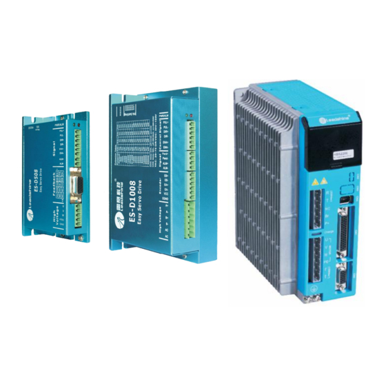
- Page 1 Hardware Installation Manual Easy Servo Drives ES-D808/1008 ES-D2306 ES-D508 HMN_ES_R20130312 http://www.Leadshine.com...
- Page 2 Read this manual carefully before trying to install the stepper drive into your system. The people who setup the stepper drive should have a better understanding on electronics and mechanics. Contact Leadshine technical guys Notice when you have questions on this document.
-
Page 3: Table Of Contents
Table of Contents Introduction to Easy Servo ........................1 Getting Start ............................1 Wiring Diagrams .......................... 2 Connecting Power Supply ......................3 ES-D508, ES-D808........................3 ES-D1008..........................4 ES-D2306..........................4 Connecting Motor......................... 5 ES-D508 and ES-M323XX ....................... 5 ES-D808 and ES-M223XX ....................... 5 ES-D808/1008 and ES-M234XX .................... - Page 4 Problem Symptoms and Possible Causes ..................19 Warranty ............................20 Exclusions ........................... 20 Obtaining Warranty Service ....................... 20 Warranty Limitations........................20 Shipping Failed Product......................20 Contact Us ............................21 HWMN-ES-R20131312...
-
Page 5: Introduction To Easy Servo
Hardware Installation Manual of Easy Servo Introduction to Easy Servo The ES (Easy Servo) series close-loop stepper servos offer an alternative for applications requiring high performance and high reliability when the traditional servo was the only choice, while it remains cost-effective. -
Page 6: Wiring Diagrams
Hardware Installation Manual of Easy Servo Wiring Diagrams RS232 Cable USB-232 Converter Motion Controller Power Supply Encoder Cable Motor Power Cable Wiring Diagram of ES-D508 and ES-M323XX RS232 Cable USB-232 Converter Motion Controller Power Supply Encoder Cable Motor Power Cable Wiring Diagram of ES-D808/1008 and ES-M2XXXX HWMN-ES-R20130312... -
Page 7: Connecting Power Supply
Hardware Installation Manual of Easy Servo Wiring Diagram (Continued) AC Power RS232 Cable USB-232 Converter Motion Controller Encoder Cable Motor Power Cable Wiring Diagram of ES-D2306 and ES-MH3XXXX Connecting Power Supply ES-D508, ES-D808 The easy servo drives ES-D508 and ES-D808 can accept DC power input. They have only tow wires-positive wire and negative wire for the power connection. -
Page 8: D1008
Hardware Installation Manual of Easy Servo Connecting Power Supply (Continued) ES-D1008 The ES-D1008 can accept both DC and AC power input. There is no power input polarity for it. + (Positive) DC Power - (Negative) High Voltage 30-100VDC DC Power Connection of ES-D1008 AC Power High Voltage 20-70VAC... -
Page 9: Connecting Motor
Hardware Installation Manual of Easy Servo Connecting Motor ES-D508 and ES-M323XX The ES-M323XX has three wires: U, V and W. Just connect them to the corresponding terminals of the ES-D508 as follows. ES-M323XX ES-D508 Connect ES-M323XX to ES-D508 ES-D808 and ES-M223XX The ES-M223XX has four wires: A+, A-, B+ and B-. -
Page 10: D808/1008 And Es-M234Xx
Hardware Installation Manual of Easy Servo Connecting Motor (Continued) ES-D808/1008 and ES-M234XX The ES-M234XX has four wires: A+, A-, B+ and B-. Just connect them to the corresponding terminals of the ES-D808/1008 as follows. ES-M234XX ES-D808 ES-D1008 Connect ES-M234XX to ES-D808/1008 Connecting Encoder As the Easy Servo Drive works in close-loop mode, it needs to know the actual motor position. -
Page 11: Connecting Control Signal
Hardware Installation Manual of Easy Servo Encoder Cable ES-D808/ ES-D1008 Encoder Signals EGND Color Name White Yellow Green Black ES-M223XX Blue ES-M234XX Encoder connection between ES-D808/1008 and ES-M223XX/ES-M234XX Connecting Control Signal Pulse, Direction, Enable Input The pulse, direction and enable input of the Easy Servo drive is differential. It can also be connected to PNP (sourcing) or NPN (sinking) type controller. - Page 12 Hardware Installation Manual of Easy Servo Pulse, Direction, Enable Input (Continued) In a PNP (sinking) type output, the control signals are refer to the same ground terminal. Controller ES-DXXX Step PUL+ PUL- Direction DIR+ DIR- Enable ENA+ ENA- Control Signal Connector ES-D508 R=0 if VCC=5V;...
-
Page 13: Alarm, In-Position Output
ProTuner. The ProTuner can be downloaded from our website: http://www.leadshine.com or you may also get it from our CD. It is recommended to get it from the website because it is always the latest. Install it in your PC and make it ready for use later. -
Page 14: Configuration
Hardware Installation Manual of Easy Servo When you open ProTuner, a “Connect to drive” window appears. The “Baud Rate” and “Device Address” are fixed. You only need to select the “Com Port” regarding to the actual serial port or the mapping port of a USB-232 converter. -
Page 15: Configuring Es Drive By Dip Switches
Hardware Installation Manual of Easy Servo Recommended Holding / Close-loop Current Percentage ES-M32309 ES-M32320 ES-M22310 ES-M22320 ES-M23440 ES-M23480 Holding Current (%) Close-loop 100% 100% 100% 100% 100% 100% Current Limit (%) Easy servo drive ES-D508 ES-D508 ES-D808 ES-D808 ES-D808 ES-D808 Recommended Current Loop Kp / Ki of Different Supply Voltage ES Motor ES drive... -
Page 16: D808/D1008
Hardware Installation Manual of Easy Servo ES-D808/D1008 There is a 6-bit DIP switch in the ES-D808 and ES-D1008 drive. SW1 to SW4 are used to set the micro step resolution and SW5 are used to set the direction polarity. 6-bit DIP Switches in ES-D808/ES-D1008 SW5 is used to reverse the motion direction. -
Page 17: Configuring Es Drive In Pc Software
Hardware Installation Manual of Easy Servo Configuring ES drive in PC Software Consult the “Connecting to PC Software” chapter for how to connect the Easy Servo drive to PC. Suppose the tuning software has been open, click the “Drive->Parameters” to open the Tool->Drive Parameters window. -
Page 18: Rotating The Easy Servo Motor By Motion Controller
Hardware Installation Manual of Easy Servo Rotating the Easy Servo Motor by Motion Controller Now everything is ready. You can start the controller or pulse generator to rotate the motor. Actually, any device which gives high-to-low or low-to-high level changes can be used to move the motor. If it is your first time installation, it is recommended to disconnect the motor shaft from the load in case of accident. -
Page 19: Power Supply Selection
Hardware Installation Manual of Easy Servo Power Supply Selection To achieve good driving performances, it is important to choose a suitable supply voltage and use a matching current value. Generally speaking, supply voltage determines the high speed performance of the motor, while output current determines the output torque of the driven motor (particularly at lower speed). -
Page 20: Recommended Supply Voltage
Driver Lower Input limit Driver Input Voltage Driver Input Voltage Power Supply Voltage Power Supply Voltage Recommended Supply Voltage Both Leadshine’s regulated and unregulated power supply has been designed specially for motion control. Motor Drive Voltage Range Typical Voltage Leadshine Power Supply... -
Page 21: Control Signal Setup Timing
>50ms Current Control Detail Leadshine’s hybrid servo motor is integrated with a high-resolution 1,000-line optical incremental encoder. That encoder can send the real-time shaft position back to the hybrid drive. Like traditional servo controls, the drive can automatically adjust the output current to the motor. The output current ranges between the holding current and the close-loop current. -
Page 22: Fine Tuning
However, if you want to fine tune the IES for best performance for your applications, Leadshine also offers tuning software, ProTuner, which allows you to adjust those current-loop and position-loop parameters (see software manual). -
Page 23: Position Following Error Protection
Hardware Installation Manual of Easy Servo Position Following Error Protection When the position error exceeds the limit (software configurable, see software manual), position, protection will be activated and red LED will blink seven times within each periodic time. Frequently Asked Questions In the event that your drive doesn’t operate properly, the first step is to identify whether the problem is electrical or mechanical in nature. -
Page 24: Warranty
Leadshine Technology Co., Ltd. warrants its products against defects in materials and workmanship for a period of 12 months from shipment out of factory. During the warranty period, Leadshine will either, at its option, repair or replace products which proved to be defective. -
Page 25: Contact Us
Web: http://www.leadshine.com Sales Hot Line: Tel: 86-755-2641-7674 (for Asia, Australia, Africa areas) 86-755-2640-9254 (for Europe areas) 86-755-2641-7617 (for America areas) Fax: 86-755-2640-2718 Email: sales@leadshine.com. Technical Support: Tel: 86-755-2641-8447, 86-755-2641-8774, 86-755-2641-0546 Fax: 86-755-2640-2718 Email: tech@leadshine.com(for All) Leadshine U.S.A Address: 25 Mauchly, Suite 318 Irvine, California 92618...
Need help?
Do you have a question about the Easy Servo Series and is the answer not in the manual?
Questions and answers