Fuji Electric FRENIC-HVAC User Manual
Frenic-hvac series
Hide thumbs
Also See for FRENIC-HVAC:
- Instruction manual (39 pages) ,
- Manual (140 pages) ,
- Manual (24 pages)
Table of Contents
Advertisement
Quick Links
Download this manual
See also:
Instruction Manual
Advertisement
Chapters
Table of Contents

Related Manuals for Fuji Electric FRENIC-HVAC


Summary of Contents for Fuji Electric FRENIC-HVAC
- Page 1 24A7-E-0069d...
- Page 3 User's Manual...
- Page 4 Copyright © 2012-2016 Fuji Electric Corp. of America All rights reserved. No part of this publication may be reproduced or copied without prior written permission from Fuji Electric Corp. of America. All products and company names mentioned in this manual are trademarks or registered trademarks of their respective holders.
- Page 5 Incorrect handling of the inverter may prevent the inverter and/or related equipment from operating correctly, shorten their lives, or cause problems. The table below lists the other materials related to the use of the FRENIC-HVAC. Read them in conjunction with this manual as necessary.
- Page 6 Safety precautions Read this manual and the FRENIC-HVAC Instruction Manual (that comes with the product) thoroughly before proceeding with installation, connections (wiring), operation, or maintenance and inspection. Ensure you have sound knowledge of the product and familiarize yourself with all safety information and precautions before proceeding to operate the inverter.
- Page 7 Chapter 6 FUNCTION CODES This chapter contains overview tables of 12 groups of function codes available for the FRENIC-HVAC series of inverters, function code index by purpose, and details of function codes. Chapter 7 BLOCK DIAGRAMS FOR CONTROL LOGIC This chapter provides the main block diagrams for the control logic of the FRENIC-HVAC series of inverters.
- Page 8 Chapter 11 CONFORMITY WITH STANDARDS This chapter sets forth the conformity with overseas standards. Appendices Icons The following icons are used throughout this manual. This icon indicates information which, if not heeded, can result in the inverter not operating to full efficiency, as well as information concerning incorrect operations and settings which can result in accidents.
-
Page 9: Table Of Contents
1.2 Inspection of goods and product appearance ..................1-13 1.2.1 Inspection of goods ........................1-13 1.2.2 Product appearance ........................1-15 Chapter 2 SPECIFICATIONS 2.1 Standard Model FRENIC-HVAC ......................2-1 2.1.1 Three-phase 230 V class series (USA models) ..................2-1 2.1.2 Three-phase 460 V class series (USA models) ................... - Page 10 4.3.1 Molded case circuit breaker (MCCB), residual-current-operated protective device (RCD)/ earth leakage circuit breaker (ELCB) and magnetic contactor (MC) ..........4-5 4.3.2 Surge killers for L-load ........................4-10 4.3.3 Arresters ............................4-11 4.3.4 Surge absorbers ..........................4-12 4.4 Options ..............................4-13 4.4.1 Selecting peripheral equipment options ....................
- Page 11 5.2 Mounting and Connecting a Keypad ......................5-21 5.2.1 Parts required for connection ......................5-21 5.2.2 Mounting procedure .......................... 5-21 5.3 Operation Using the Keypad ........................5-24 5.3.1 LCD monitor, keys and LED indicators on the keypad ..............5-24 5.4 Overview of Operation Modes ........................5-28 5.5 Running Mode ............................
- Page 12 5.7.5 Checking prior to powering ON ......................5-99 5.7.6 Powering ON and checking......................5-100 5.7.7 Selecting a desired motor drive control ................... 5-100 5.7.8 Function code basic settings < 1 > ....................5-101 5.7.9 Function code basic settings and tuning < 2 > ................5-103 5.7.10 Running the inverter for motor operation check ................
- Page 13 9.1 Protective Functions ............................ 9-1 9.2 Before Proceeding with Troubleshooting ....................9-2 9.3 If an Alarm Code Appears on the Monitor ....................9-3 9.3.1 Alarm Codes ............................9-3 9.3.2 If the "Light Alarm" Indication Appears ................... 9-22 9.4 Nothing appears on the monitor ........................ 9-24 9.4.1 Abnormal motor operation ........................
- Page 15 Chapter 1 About FRENIC-HVAC This chapter describes the features, control system, outer appearance and recommended configuration of peripheral equipment for FRENIC-HVAC. Contents Features ..............................1-1 Inspection of goods and product appearance ................... 1-13 1.2.1 Inspection of goods ......................... 1-13 1.2.2...
-
Page 17: Features
1.1 Features Features Overview FRENIC-HVAC is Fuji Electric’s first “slim-type inverter specially designed for saving energy.” The device is ideal for all kinds of applications related to systems for supplying water and treating wastewater. Achieving significant energy savings in HVAC by the optimal control. - Page 18 4PID control (standardly equipped with 4PID) ∙ PID control (for process) Can be used by switching 2 types of process commands and feedback value. “Filter clogging / anti-jam, deviation alarm / absolute value alarm output” have been added to PID regulator that conducts temperature, pressure or flow rate control, etc.
- Page 19 1.1 Features ● Fire Mode (forced operation) Alarm is ignored and operation continues until the inverter is damaged, and evacuation route is secured without smoke permeation. Pick-up operation function (speed sensor) Smooth start by pick-up function. If operating fan while operating without a load Power source Instantaneous...
- Page 20 ● Customizable logic The customizable logic interface function is provided to the inverter body. This enables forming of logic circuit and arithmetic circuit to the digital and analog input and output signals, allowing simple relay sequence to be built while processing the signals freely. Example: Digital (AND + on-delay timer) Example: Analog (subtraction + comparison 5) Step 2...
- Page 21 1.1 Features ● Trip-less by regenerative avoidance control (effective for acceleration, deceleration and fixed speed) Because amount of energy to be regenerated to the inverter is limited and acceleration/deceleration time is controlled, equipment can be operated without overvoltage trip. <Example: Operation when decelerating> command Rotation speed...
- Page 22 The inverter is equipped with 2 types of commercial operation switching sequences: Fuji standard and inverter alarm automatic commercial switching sequence. ELCB or MCCB Power FRENIC-HVAC Built-in On/Off sequence Commercial/inverter ● Operation signal trouble is also avoided by command loss detection function.
- Page 23 1.1 Features ● Password function Function codes can be read/write, displayed or hidden by setting the two passwords. This prevents erroneous operation or overwriting of function codes. In addition, if a wrong password was input exceeding the specified number of times, the inverter is restricted from operating as the user is regarded as improper.
- Page 24 Therefore, the fan keeps rotating at high speed, failing in energy-saving operation. FRENIC-HVAC automatically estimates the wet-bulb temperature and controls the fan so that the cooling water is interlocked with the air...
- Page 25 1.1 Features ● Linearization function This function estimates the target pressure using the load flow rate, which allows the estimated terminal pressure to be controlled. For an air-conditioning heat source system, the needed quantity of the cooling or heating water fluctuates generally in seasons or days and nights. Therefore, operations continuing in a water conveyance pressure constant control may lead to high operating unnecessary pressures on terminals at low operating state.
- Page 26 Simple and enhanced maintenance / enhanced protective functions. Information concerning life of consumable inverter parts is displayed. Cooling fan cumulative running time Main circuit capacitance (Equipped with cooling fan ON/OFF control compensation) Inverter cumulative running Electrolytic capacitors on PC board time Cumulative running time ...
- Page 27 1.1 Features Motor protection by PTC thermistor By connecting the Positive Temperature Coefficient (PTC) thermistor embedded in the motor to the C1 pin, motor temperature is detected to protect the motor by shutting off the inverter before the motor overheats. You can select whether to shut off the inverter (stop by alarm) or output alarm from transistor output by PTC protection level.
- Page 28 Equipped with keypad employing large LCD. ∙ Realizes regulator display by enlargement of LCD. 1. Present value (PV) 6. Output voltage 2. Setting value (SV) 7. Torque 3. Manipulating value (MV) 8. Rotation speed 4. Frequency 9. Power consumption 5.
-
Page 29: Inspection Of Goods And Product Appearance
1.2 Inspection of goods and product appearance Inspection of goods and product appearance 1.2.1 Inspection of goods Unpack the package and check the following: (1) An inverter and the following accessories are contained in the package. Accessories: Instruction manual and CD-ROM manual (2) The inverter has not been damaged during transportation—there should be no dents or parts missing. - Page 30 The alphabetical character that indicates protective structure goes in . If there is something you do not understand about the product or there is something wrong with it, please contact the dealership from where you purchased it or your nearest Fuji Electric sales office. 1-14...
-
Page 31: Product Appearance
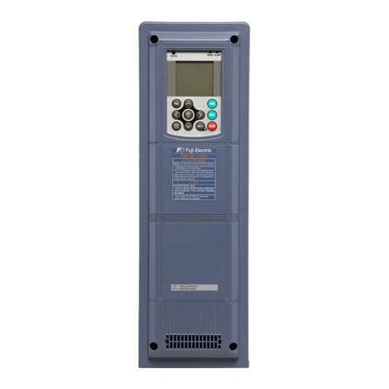
1.2 Inspection of goods and product appearance 1.2.2 Product appearance Fig. 1.1 FRN001AR1M-4U (NEMA/UL type1) Front cover Cooling fan Front cover mounting screw Internal Keypad Control circuit terminal block agitator fan Main circuit terminal block Caution label Front cover Ratings label Fig. - Page 32 This chapter describes specifications of the output ratings, control system, and terminal functions for the FRENIC-HVAC series of inverters. It also provides descriptions of the operating and storage environment, precautions for using inverters, external dimensions, examples of basic connection diagrams, and details of the protective functions.
-
Page 34: Standard Model Frenic-Hvac
2.1 Standard Model 2.1 Standard Model FRENIC-HVAC 2.1.1 Three-phase 230 V class series (USA models) (001 to 125 HP) Item Specifications Type (FRN_ _ _AR1-2U) (*1) Nominal Three AC208V applied motor phase motor [HP] (*2) input AC230V (Rated output) motor... - Page 35 (*1) A box () replaces an alphabetic letter depending on the enclosure. Enclosure: M (NEMA/UL Type1), L (NEMA/UL Type12) or S (UL Open Type) (*2) US 4-pole standard induction motor. (*3) Rated capacity is calculated by assuming the output rated voltage as 230 V. (*4) Output voltage cannot exceed the power supply voltage.
-
Page 36: Three-Phase 460 V Class Series (Usa Models)
2.1 Standard Model 2.1.2 Three-phase 460 V class series (USA models) (1 to 75 HP) Item Specifications Type (FRN_ _ _AR1-4U) (*1) Nominal Three AC460V applied motor phase motor [HP] (*2) input (Rated output) Single phase input Three Rated capacity (kVA) phase (*3) input... - Page 37 (100 to 1000 HP) Item Specifications Type 1000 (FRN_ _ _AR1-4U) (*1) Nominal Three AC460V applied phase 1000 motor motor (HP) input (*2) Single (Rated phase output) input Three Rated capacity (kVA) 1091 phase (*3) input Rated current (A) 1170 1370 Single Rated capacity (kVA)
- Page 38 2.1 Standard Model (*1) A box () replaces an alphabetic letter depending on the enclosure. Enclosure: M (NEMA/UL Type1), L (NEMA/UL Type12) or S (UL Open Type) (*2) US 4-pole standard induction motor. (*3) Rated capacity is calculated by assuming the output rated voltage as 460 V. (*4) Output voltage cannot exceed the power supply voltage.
-
Page 39: Three-Phase 575 V Class Series (Usa Models)
2.1.3 Three-phase 575 V class series (USA models) (001 to 050 HP) Item Specifications Type (FRN_ _ _AR1-5U) (*1) Nominal Three AC575V applied motor phase motor [HP] (*2) input (Rated output) Single phase input Three Rated capacity (kVA) phase (*3) input Rated current (A) Single... - Page 40 2.1 Standard Model (060to 300HP) Item Specifications Type (FRN_ _ _AR1-5U) (*1) Nominal Three AC575V applied motor phase motor [HP] (*2) input (Rated output) Single phase input Three Rated capacity (kVA) phase (*3) input Rated current (A) Single Rated capacity (kVA) phase (*3) input...
- Page 41 (*1) A box () replaces an alphabetic letter depending on the enclosure. Enclosure: M (NEMA/UL Type1), L (NEMA/UL Type12) or S (UL Open Type) (*2) US 4-pole standard induction motor. (*3) Rated capacity is calculated by assuming the output rated voltage as 575 V. (*4) Output voltage cannot exceed the power supply voltage.
-
Page 42: Common Specifications
2.2 Common Specifications 2.2 Common Specifications Item Explanation Remarks Maximum 25 to 120 Hz variable setting frequency Base frequency 25 to 120 Hz variable setting Starting frequency 0.1 to 60.0 Hz variable setting 230 V class series: • 0.75 to 16 kHz variable setting ( 1 to 25 HP ) •... - Page 43 Item Explanation Remarks Keypad: Settable with keys "+1 to +5 VDC" External volume: Can be set with external frequency command potentiometer. (1 to 5 kΩ can be 1/2 W) adjusted Analog input: 0 to ±10 V DC (±5 V DC) / 0 to ±100% (terminals [12] and [V2]), with bias 0 to +10 V DC (+5 V DC) / 0 to +100% (terminals [12] and [V2]) : +4 to +20 mA DC / 0 to 100% (terminal [C1])
- Page 44 2.2 Common Specifications Item Explanation Remarks • SW50 ("Switch to commercial power 50 Hz") or SW60 ("Switch to commercial power Run by commercial 60 Hz") switches the inverter to 50 or 60 Hz output, respectively. power supply • Built-in commercial power supply switching sequence Slip compensation Compensates for decrease in speed according to the load.
- Page 45 Item Explanation Remarks Restriction on rotation Reverse or forward rotation prevention. direction Dew condensation When the motor is stopped, current is automatically supplied to the motor to keep the prevention motor warm and avoid condensation. Customizable logic 2 inputs, 1 output, logical operation, timer function, four arithmetic operations of analog interface amount, comparison and conversion, choice of maximum/minimum, 14 steps •...
- Page 46 2.2 Common Specifications Item Explanation Remarks Overcurrent protection Protects the inverter from overcurrent caused by overload and stops the inverter. Protects the inverter from overcurrent caused by a short-circuit in the output circuit and Short-circuit protection stops the inverter. Protects the inverter from overcurrent caused by a ground fault in the output circuit and stops the inverter.
- Page 47 Item Explanation Remarks Option Upon detection of an error in communication between the inverter and an option card, this communications error function stops the inverter output. Option error When an option card detects an error, this function stops the inverter output. STOP key priority: Pressing the key on the keypad forcibly decelerates the motor to a stop even when a run command is given via the terminal block or communications link.
- Page 48 2.2 Common Specifications Item Explanation Remarks When the output current exceeds the current limiter level during acceleration/deceleration Stall prevention or running at constant speed, this function decreases the output frequency to avoid an overcurrent trip. When the inverter has stopped because of a trip, this function allows the inverter to automatically reset itself and restart.
-
Page 49: Terminal Specifications
P(+), N(-) DC link bus To be used for connecting a DC link bus. For use of these terminals, consult your Fuji Electric representative. R1, T1 Auxiliary main Usually there is no need to do anything for these terminals. To be circuit power used when the inverter is combined with a PWM converter. - Page 50 2.3 Terminal Specifications Symbol Name Functions [C1] Analog setting (1) The frequency is commanded according to the external analog current input current input. (C1 function) • 4 to 20 mA DC/0 to 100% (Normal operation) • 0 to 20 mA DC/0 to 100% (Normal operation) •...
- Page 51 Related Symbol Name Functions function codes - Since low level analog signals are handled, these signals are especially susceptible to the external noise effects. Route the wiring as short as possible (within 20 m (66 ft)) and use shielded wires. In principle, ground the shielded sheath of wires; if effects of external inductive noises are considerable, connection to terminal [11] may be effective.
- Page 52 2.3 Terminal Specifications Digital Input Terminals Symbol Name Functions (1) Various signals such as "Coast to a stop," "Enable external [X1] Digital input 1 alarm trip," and "Select multistep frequency" can be assigned [X2] Digital input 2 to terminals [X1] to [X7], [FWD] and [REV] by setting function codes E01 to E07, E98, and E99.
- Page 53 Symbol Name Functions (1) Opening terminals [EN1] and [PLC] or terminals [EN2] and Enable input 1 [EN1] [PLC] stops the inverter's output transistor. (Safe Torque Off, STO) (2) These terminals are exclusively used for the SOURCE mode Enable input 2 [EN2] input and cannot be switched to the SINK mode input.
- Page 54 2.3 Terminal Specifications Symbol Name Functions Using a programmable logic controller (PLC) to turn [X1] to [X7], [FWD], or [REV] ON or OFF Figure 2.7 shows two examples of a circuit that uses a programmable logic controller (PLC) to turn control signal input [X1] to [X7], [FWD], or [REV] ON or OFF. In circuit (a), the slide switch SW1 is turned to SINK, whereas in circuit (b) it is turned to SOURCE.
- Page 55 Analog output, transistor output, and relay output terminals Symbol Name Functions [FM1] Analog monitor These terminals output monitor signals of analog DC voltage (0 to +10 V) or analog DC current (+4 to +20 mA DC or 0 to +20 [FM2] mA DC).
- Page 56 2.3 Terminal Specifications Symbol Name Functions [Y1] Transistor (1) Various signals such as inverter running, frequency arrival output 1 and overload early warning can be assigned to terminals [Y1] to [Y4] by setting function code E20 to E23. Refer to Chapter [Y2] Transistor 6 "FUNCTION CODES"...
- Page 57 Related Symbol Name Functions function codes Connecting programmable logic controller (PLC) to terminal [Y1], [Y2], [Y3] or [Y4] Figure 2.9 shows two examples of circuit connection between the transistor output of the inverter’s control circuit and a PLC. In example (a), the input circuit of the PLC serves as a SINK for the control circuit output, whereas in example (b), it serves as a SOURCE for the output.
- Page 58 2.3 Terminal Specifications RS-485 communications port Connector Name Functions DX+/DX- RS-485 The communications port transmits data through the RS-485 communications multipoint protocol between the inverter and a computer or other port 2 equipment such as a PLC (Programmable Logic Controller). (Terminal block) (For setting of the terminating resistor, refer to Section 2.3.2 "Setting up the slide switches.")
-
Page 59: Setting Up The Slide Switches
2.3.2 Setting up the slide switches Before changing the switches, turn OFF the power and wait at least ten minutes. Make sure that the LCD monitor is turned OFF. Further, make sure, using a multimeter or a similar instrument, that the DC link bus voltage between the terminals P(+) and N(-) has dropped to the safe level (+25 VDC or below). - Page 60 2.3 Terminal Specifications Figure 2.11 shows the location of slide switches on the control PCB. Switching examples and factory default SW4/SW6 Shipping destination VO1/VO2 SINK FRNAR1 -2U/4U/5U Figure 2.11 Location of the Slide Switches on the Control PCB To move a switch slider, use a tool with a narrow tip (e.g., tweezers), taking care not to touch other electronic parts on the PCB.
-
Page 61: Screw Specifications And Recommended Wire Sizes
2.3.3 Screw specifications and recommended wire sizes 2.3.3.1 Main circuit terminals The specifications of the screws to use for the wiring of the main circuit are shown below. Please note that terminal arrangements vary depending on inverter capacities. Refer to 「Chapter 11 CONFORMITY WITH STANDARDS」for recommended wire size. Use crimp terminals covered with an insulation sheath or with an insulation tube. - Page 62 2.3 Terminal Specifications Screw Specifications (460 V class series) Aux. control power supply Main circuit Grounding Nominal terminals terminals Aux. main circuit Power applied Refer power supply supply Inverter type motor voltage Tightening Tightening Tightening (HP) Screw Screw Screw torque torque torque...
- Page 63 Screw Specifications (575 V class series) Aux. control power supply Main circuit Grounding Nominal terminals terminals Aux. main circuit Power applied Refer power supply supply Inverter type motor voltage Tightening Tightening Tightening (HP) Screw Screw Screw torque torque torque size size size...
- Page 64 2.3 Terminal Specifications When the inverter power is ON, a high voltage is applied to the following terminals. Main circuit terminals: L1/R, L2/S, L3/T, P(+), N(-), U, V, W, R0, T0, R1, T1, AUX-contact (30A, 30B, 30C, Y5A, Y5C) Insulation level Main circuit-Enclosure : Basic insulation (Overvoltage category III, Pollution degree 2) Main circuit-Control circuit...
- Page 65 Figure D Figure E Unit: mm (inch) (NC): No connection (Do not make wiring.) 2-32...
- Page 66 2.3 Terminal Specifications Figure F Figure G/ Figure H Figure I Unit: mm (inch) 2-33...
- Page 67 Figure J Figure K Figure L Unit: mm (inch) 2-34...
-
Page 68: Control Circuit Terminals (Common To All Inverter Types)
2.3 Terminal Specifications 2.3.3.2 Control circuit terminals (Common to all inverter types) The control circuit terminal arrangement, screw sizes, and tightening torque are shown below. The control circuit terminals are common to all inverter types regardless of their capacities. Screw type of terminal block Table 2.2 Control Circuit Terminals Screw specifications Terminal... -
Page 69: Conduits
2.4 Conduits To ensure NEMA/UL Type 12 rating, mount conduits on the wiring plate in wiring. The conduits should be selected according to the number of wires to be connected and the wire size. Sections 2.4.1 give the sizes of the conduits to be applied when the wires of the recommended sizes are used. -
Page 70: Conduits
2.4 Conduits (4) FRN030AR1■-2U, FRN040AR1■-2U, FRN060AR1■-4U, and FRN075AR1■-4U/5U (See Figure D.) Conduit body Punch-out # in wiring Recommended wiring examples BULLET Locknut Size (inch) Size (inch) plate models models H200-TB For inverter output H125-TB 1 1/4 For connection to the DC link bus For main power input and auxiliary H150-TB 1 1/2... - Page 71 Punch-out Arrangement in Wiring Plate Figure A Figure B Figure C Figure D Figure E For instructions on how to punch out semi-perforated sections in the wiring plate and set conduits on the wiring plate, refer to Chapter 5, Section 5.1.2.1 "(2) Punching out semi-perforated sections in the wiring plate and setting conduits."...
-
Page 72: Leakage Current Of The Emc Filter
2.5 Leakage Current of the EMC Filter 2.5 Leakage Current of the EMC Filter This product uses grounding capacitors for noise suppression which increase the leakage current. Check whether there is no problem with power supply systems. As the leakage current of the EMC filter is relatively high, it is important to always assure a reliable connection to Protection Earth (PE). - Page 73 Table 2.3 Leakage Current of EMC Filter(continue) Leakage current (mA) Leakage current (mA) Input Input Under Under Under Under Inverter type Inverter type power power normal worst-case normal worst-case conditions conditions conditions conditions FRN001AR1-5U FRN040AR1-5U FRN002AR1-5U FRN050AR1-5U FRN003AR1-5U FRN060AR1-5U FRN005AR1-5U FRN075AR1-5U Three- Three-...
- Page 74 Note that doing so loses the effect of the EMC filter so that the inverter is no longer compliant with the EMC standards. To remove those screws, consult your Fuji Electric representative. For the location of terminals [E1] and [E2], see the arrangement of terminals given in Section 2.3.3.1.
-
Page 75: Derating Of Rated Output Current
460V class series: FRN005AR1L-4U, FRN015AR1L-4U, FRN025AR1L-4U, FRN030AR1L-4U, FRN060AR1L-4U, FRN075AR1L-4U 230V class series: FRN020AR1L-2U, FRN025AR1L-2U Group 4 460V class series: FRN040AR1L-4U, FRN050AR1L-4U Note: About FRN030AR1L-2U to FRN060AR1L-2U, consult your Fuji Electric representative. Contact Fuji Electric for details on 575V class series derating curves. 2-42... - Page 76 2.6 Derating of Rated Output Current (2) Open type: FRN075AR1S-2U, FRN100AR1S-2U Output current derating factor (rated current ratio) Carrier frequency Ambient temperature Ambient temperature setting (kHz) 40°C(104°F) 50°C(122°F) 0.75 to 2 100% 100% 100% 100% 100% 100% 100% 100% 100% 100% 100% 100%...
-
Page 77: Operating Environment And Storage Environment
2.7 Operating Environment and Storage Environment 2.7.1 Operating environment Install the inverter in an environment that satisfies the requirements listed below. Table 2.4 Environmental Requirements Item Specifications Site location Indoors NEMA/UL TYPE 1 Ambient -10 to +50°C (14 to 122°F) temperature (-10 to +40°C (14 to 104°F) for inverters mounted closely side by side*) +50 to +60°C (122 to 140°F) (when current derating ) -
Page 78: Storage Environment
2.7 Operating Environment and Storage Environment 2.7.2 Storage environment 2.7.2.1 Temporary storage Store the inverter in an environment that satisfies the requirements listed below. Table 2.6 Storage and Transport Environments Item Specifications -25 to +70°C (-13 to +158°F) Storage temperature Places not subjected to abrupt temperature changes or condensation or freezing Relative... -
Page 79: Precautions For Using Inverters
Install the inverter in an environment that satisfies the requirements listed in Table 2.4 in Section 2.7.1. Fuji Electric strongly recommends installing inverters in a panel for safety reasons, in particular, when installing the ones whose enclosure rating is UL open type. - Page 80 For an inverter with an output circuit filter installed, the total secondary wiring length should be 400 m (1312 ft) or less. If further longer secondary wiring is required, consult your Fuji Electric representative. (5) Precautions for surge voltage in driving a motor by an inverter...
- Page 81 (6) When an output circuit filter is inserted in the secondary circuit or the wiring between the inverter and the motor is long, a voltage loss occurs due to reactance of the filter or wiring so that the insufficient voltage may cause output current oscillation or a lack of motor output torque. To avoid it, select the constant torque load by setting the function code F37 (Load Selection/Auto Torque Boost/Auto Energy Saving Operation 1) to "1"...
- Page 82 2.8 Precautions for Using Inverters Noise reduction If noise generated from the inverter affects other devices, or that generated from peripheral equipment causes the inverter to malfunction, follow the basic measures outlined below. (1) If noise generated from the inverter affects the other devices through power wires or grounding wires: - Isolate the grounding terminals of the inverter from those of the other devices.
-
Page 83: Precautions In Running Inverters
2.8.2 Precautions in running inverters Precautions for running inverters to drive motors or motor-driven machinery are described below. Motor temperature When an inverter is used to run a general-purpose motor, the motor temperature becomes higher than when it is operated with a commercial power supply. In the low-speed range, the motor cooling effect will be weakened, so decrease the output torque of the motor when running the inverter in the low-speed range. -
Page 84: External Dimensions
2.9 External Dimensions 2.9 External Dimensions 2.9.1 Standard models FRN001AR1-2U to FRN005AR1-2U, FRN001AR1-4U to FRN010AR1-4U, FRN001AR1-5U to FRN010AR1-5U Figure 1 External Dimensions of the Inverter 2-51... - Page 85 FRN007AR1-2U to FRN015AR1-2U, FRN015AR1-4U to FRN030AR1-4U, FRN015AR1-5U to FRN030AR1-5U Figure 2 External Dimensions of the Inverter 2-52...
- Page 86 2.9 External Dimensions FRN020AR1-2U, FRN025AR1-2U, FRN040AR1-4U, FRN050AR1-4U, FRN040AR1-5U, FRN050AR1-5U Figure 3 External Dimensions of the Inverter 2-53...
- Page 87 FRN030AR1-2U, FRN040AR1-2U, FRN060AR1-4U, FRN075AR1-4U FRN060AR1-5U, FRN075AR1-5U Figure 4 External Dimensions of the Inverter 2-54...
- Page 88 2.9 External Dimensions FRN050AR1-2U, FRN060AR1-2U, FRN100AR1-4U, FRN125AR1-4U FRN100AR1-5U, FRN150AR1-5U Figure 5 External Dimensions of the Inverter 2-55...
- Page 89 FRN075AR1S-2U, FRN100AR1S-2U Panel cutout Figure 6 External Dimensions of the Inverter 2-56...
- Page 90 2.9 External Dimensions FRN125AR1S-2U Panel cutout Figure 7 External Dimensions of the Inverter 2-57...
- Page 91 FRN150AR1S-4U, FRN200AR1S-4U, Panel cutout Figure 8 External Dimensions of the Inverter 2-58...
- Page 92 2.9 External Dimensions FRN250AR1S-4U, FRN300AR1S-4U, FRN200AR1S-5U, FRN300AR1S-5U Panel cutout Figure 9 External Dimensions of the Inverter 2-59...
- Page 93 FRN350AR1S-4U, FRN450AR1S-4U Panel cutout Figure 10 External Dimensions of the Inverter 2-60...
- Page 94 2.9 External Dimensions FRN500AR1S-4U, FRN600AR1S-4U Panel cutout Figure 11 External Dimensions of the Inverter 2-61...
- Page 95 FRN800AR1S-4U Panel cutout Figure 12 External Dimensions of the Inverter 2-62...
- Page 96 2.9 External Dimensions FRN900AR1S-4U, FRN1000AR1S-4U Panel cutout Figure 13 External Dimensions of the Inverter 2-63...
-
Page 97: Keypad
2.9.2 Keypad 2-64... -
Page 98: Connection Diagrams
2.9 External Dimensions 2.10 Connection Diagrams [ 1 ] FRN060AR1 - 2U / FRN125AR1 -4 U / FRN150AR1 -5 U or below and SINK mode input with Enable input function used (factory default) Power supply 230V class series 200 to 240 V 50/60 Hz 400V class series 380 to 480 V... - Page 99 SOURCE mode input with Enable input function used Power supply 230V class series 200 to 240 V 50/60 Hz 400V class series 380 to 480 V 50/60 Hz 575V class series 575 to 600 V 50/60 Hz 2-66...
- Page 100 2.9 External Dimensions [ 2 ] FRN075AR1S-2U or above and FRN150AR1S-4U or above and FRN200AR1S-5U or above SINK mode input with Enable input function used (factory default) Power supply 230V class series 200 to 240 V 50/60 Hz 400V class series 380 to 480 V 50/60 Hz 575V class series...
- Page 101 SOURCE mode input with Enable input function used Power supply 230V class series 200 to 240 V 50/60 Hz 400V class series 380 to 480 V 50/60 Hz 575V class series 575 to 600 V 50/60 Hz 2-68...
- Page 102 EMC filter so that the inverter is no longer compliant with the EMC standards. To remove those screws, consult your Fuji Electric representative. *11 Usually there is no need to do anything for these terminals. To be used when the inverter is combined with a power regenerative PWM converter (RHC series).
- Page 103 Chapter 3 SELECTING OPTIMAL MOTOR AND INVERTER CAPACITIES This chapter provides you with information about the inverter output torque characteristics, selection procedure, and equations for calculating capacities to help you select optimal motor and inverter models. It also helps you select braking resistors. Contents 3.1 Selecting Motors and Inverters ........................
-
Page 105: Selecting Motors And Inverters
(1) above, calculate the acceleration/deceleration/braking torque. This section describes the selection procedure for (1) and (2) above. First, it explains the output torque obtained by using the motor driven by the inverter (FRENIC-HVAC). 3.1.1 Motor output torque characteristics Figures 3.1 and 3.2 graph the output torque characteristics of motors at the rated output frequency... - Page 106 Output frequency (Hz) -100 -150 -200 -250 Figure 3.2 Output Torque Characteristics (Base frequency: 60 Hz) Continuous allowable driving torque (Curve (a) in Figures 3.1 and 3.2) Curve (a) shows the torque characteristic that can be obtained in the range of the inverter continuous rated current, where the motor cooling characteristic is taken into consideration.
-
Page 107: Selection Procedure
3.1 Selecting Motors and Inverters 3.1.2 Selection procedure Figure 3.3 shows the general selection procedure for optimal inverters. Items numbered (1) through (3) are described on the following pages. You may easily select inverter capacity if there are no restrictions on acceleration and deceleration times. - Page 108 Calculating the load torque during constant speed running (For detailed calculation, refer to Section 3.1.3.1) It is essential to calculate the load torque during constant speed running for all loads. First calculate the load torque of the motor during constant speed running and then select a tentative capacity so that the continuous rated torque of the motor during constant speed running becomes higher than the load torque.
- Page 109 3.1 Selecting Motors and Inverters Deceleration time (For detailed calculation, refer to Section 3.1.3.2) To calculate the deceleration time, check the motor deceleration torque characteristics for the whole range of speed in the same way as for the acceleration time. 1) Calculate the total moment of inertia for the load and motor Same as for the acceleration time.
-
Page 110: Equations For Selections
3.1.3 Equations for selections 3.1.3.1 Load torque during constant speed running [ 1 ] General equation The frictional force acting on a horizontally moved load must be calculated. Calculation for driving a load along a straight line with the motor is shown below. Where the force to move a load linearly at constant speed υ... -
Page 111: Calculation Of Acceleration/Deceleration Time
3.1 Selecting Motors and Inverters 3.1.3.2 Calculation of acceleration/deceleration time When an object whose moment of inertia is J (kg·m ) rotates at the speed N (r/min), it has the following kinetic energy: π • (3.5) • To accelerate the above rotational object, the kinetic energy will be increased; to decelerate the object, the kinetic energy must be discharged. - Page 112 Table 3.1 Moment of Inertia of Various Rotating Bodies Mass: W (kg) Mass: W (kg) Shape Shape Moment of inertia: Moment of inertia: J (kg·m J (kg·m π Hollow cylinder ρ − ρ • • • • • • • •...
- Page 113 3.1 Selecting Motors and Inverters For a load running horizontally Assume a carrier table driven by a motor as shown in Figure 3.7. If the table speed is υ (m/s) when the motor speed is N (r/min), then an equivalent distance from the shaft is equal to 60·υ / (2π·N ) (m).
-
Page 114: Heat Energy Calculation Of Braking Resistor
3.1.3.3 Heat energy calculation of braking resistor If the inverter brakes the motor, the kinetic energy of mechanical load is converted to electric energy to be transmitted into the inverter circuit. This regenerative energy is often consumed in so-called braking resistors as heat. The following explains the braking resistor rating. [ 1 ] Calculation of regenerative energy In the inverter operation, one of the regenerative energy sources is the kinetic energy that is generated at the time an object is moved by an inertial force. - Page 115 Chapter 4 SELECTING PERIPHERAL EQUIPMENT This chapter describes how to use a range of peripheral equipment and options, FRENIC-HVAC's configuration with them, and requirements and precautions for selecting wires and crimp terminals. Contents 4.1 Configuring the FRENIC-HVAC ........................ 4-1 4.2 Currents flowing across the inverter terminals .................... 4-2 4.3 Peripheral Equipment ..........................
- Page 116 4.5 Backup Battery ............................4-79 4.5.1 Outline ............................... 4-79 4.5.2 Loading the battery ........................... 4-80 4.5.3 Battery replacement procedure ......................4-82 4.5.4 About air transport of batteries ......................4-82...
-
Page 117: Configuring The Frenic-Hvac
4.1 Configuring the FRENIC-HVAC Configuring the FRENIC-HVAC This section lists the names and features of peripheral equipment and options for the FRENIC-HVAC series of inverters and includes a configuration example for reference. Figure 4.1 Configuration Example... -
Page 118: Currents Flowing Across The Inverter Terminals
Currents flowing across the inverter terminals Table 4.1 summarizes average (effective) electric currents flowing across the terminals of each inverter model for ease of reference when you select peripheral equipment and options. Table 4.1 Currents Flowing through Inverter 60 Hz, 230 V Nominal applied Power supply motor... - Page 119 4.2 Selecting Wire Size Table 4.1 Currents Flowing through Inverter (continued) 460 V, 60 Hz Nominal applied Power supply motor Inverter type Input RMS current DC link bus current voltage (HP) FRN001AR1-4U FRN002AR1-4U FRN003AR1-4U FRN005AR1-4U FRN007AR1-4U 11.1 FRN010AR1-4U 12.1 14.9 FRN015AR1-4U 18.0 22.1...
- Page 120 Table 4.1 Currents Flowing through Inverter (continued) 575 V, 60 Hz Nominal applied Power supply motor Inverter type Input RMS current DC link bus current voltage (HP) FRN001AR1-5U FRN002AR1-5U FRN003AR1-5U FRN005AR1-5U FRN007AR1-5U FRN010AR1-5U FRN015AR1-5U 14.4 FRN020AR1-5U 19.5 FRN025AR1-5U 24.0 FRN030AR1-5U 28.6 Three-phase 575 V...
-
Page 121: Peripheral Equipment
4.3 Peripheral Equipment Peripheral Equipment 4.3.1 Molded case circuit breaker (MCCB), residual-current-operated protective device (RCD)/earth leakage circuit breaker (ELCB) and magnetic contactor (MC) [ 1 ] Functional overview MCCBs and RCDs/ELCBs* * With overcurrent protection Molded Case Circuit Breakers (MCCBs) are designed to protect the power circuits between the power supply and inverter's main circuit terminals ([L1/R], [L2/S] and [L3/T]) from overload or short-circuit, which in turn prevents secondary accidents caused by the broken inverter. - Page 122 Driving the motor using commercial power lines MCs can also be used to switch the power supply of the motor driven by the inverter to a commercial power supply. Select the MC so as to satisfy the rated currents listed in Table 4.1, which are the most critical RMS currents for using the inverter.
- Page 123 4.3 Peripheral Equipment Table 4.4 Rated Current of Molded Case Circuit Breaker (MCCB), Residual-Current-Operated Protective Device (RCD)/Earth Leakage Circuit Breaker (ELCB) and Magnetic Contactor (MC) Nominal MCCB, Power supply applied motor Inverter type RCD/ELCB voltage For input circuit For input circuit (HP) Rated current (A) FRN001AR1-2U...
- Page 124 Table 4.4 Rated Current of Molded Case Circuit Breaker (MCCB), Residual-Current-Operated Protective Device (RCD)/Earth Leakage Circuit Breaker (ELCB) and Magnetic Contactor (MC) (continued) Nominal MCCB, Power supply applied motor Inverter type RCD/ELCB voltage For input circuit For output circuit (HP) Rated current (A) FRN001AR1-4U FRN002AR1-4U...
- Page 125 4.3 Peripheral Equipment Table 4.4 Rated Current of Molded Case Circuit Breaker (MCCB), Residual-Current-Operated Protective Device (RCD)/Earth Leakage Circuit Breaker (ELCB) and Magnetic Contactor (MC) (continued) Nominal MCCB, Power supply applied motor Inverter type RCD/ELCB voltage For input circuit For output circuit (HP) Rated current (A) FRN001AR1-5U...
-
Page 126: Surge Killers For L-Load
(The surge killer is available for inverters of 5 HP or less.) Refer to the catalog "Fuji Surge Killers/Absorbers (HS118: Japanese edition only)" for details. These products are available from Fuji Electric Technica Co., Ltd. Note: Do not connect the surge killers to the secondary (output) circuit of the inverter. -
Page 127: Arresters
*2 MCCB when the short-circuit current of the circuit is 250 VAC, 10 kA or less. (N-phase terminal is only for CN5234 and CN5234-K.) Available from Fuji Electric Technica Co., Ltd. Figure 4.4 Arrester Dimensions and Connection Examples 4-11... -
Page 128: Surge Absorbers
Surge absorbers cannot be used with the 575V class series. Applicable surge absorber models are the S2-A-O and S1-B-O. Figure 4.5 shows their external dimensions. The surge absorbers are available from Fuji Electric Technica Co., Ltd. Figure 4.5 Surge Absorber Dimensions 4-12... -
Page 129: Options
75HP or above and 460 V ones of 150 HP or above, remove the connector of the EMC filter. Fire or an accident could occur. When replacing conventional models (FRENIC5000VG7S, FRENIC5000G11S) with the FRENIC-HVAC, it may be necessary to change wiring. - Page 130 [ 2 ] Specifications [2.1] Standard specifications 230 V class series Item Standard specifications 230 V class series Type RHC-2C 18.5 Applicable inverter capacity (HP) Applicable inverter 18.5 capacity (kW) Continuous capacity (kW) Overload rating 150% of continuous rating for 1 min Voltage 200 V 320 to 355 V (Variable with input power voltage) (*1) Required power supply...
- Page 131 4.4 Options 460 V class series Item Standard specifications 460 V class series Type RHC-4C 7.5 11 15 18.5 22 30 37 45 55 75 90 110 132 160 200 220 280 315 355 400 500 630 Applicable inverter 10 15 20 25 30 40 50 60 75 100 125 150 200 250 300 350 450 475 500 600 800 900 capacity (HP) Applicable inverter...
- Page 132 Item Specifications Alarm display AC fuse blown, AC overvoltage, AC undervoltage, AC overcurrent, AC input (Protective functions) current error, input phase loss, synchronous power supply frequency error, DC fuse blown, DC overvoltage, DC undervoltage, charge circuit fault, heat sink overheat, external alarm, converter internal overheat, overload, memory error, keypad communications error, CPU error, network device error, operation procedure error, A/D converter error, optical network error, IPM error...
- Page 133 4.4 Options Symbol Name Functions [30A/B/C] Alarm relay output Outputs a signal when the protective function is activated to stop (for any alarm) the converter. (Contact: [1C], Terminals [30A] and [30C] are closed: Signal ON) (Contact rating: 250 VAC, max. 50 mA) 0: Converter running General-purpose [Y1], [Y2],...
- Page 134 (3) Function settings Function Function Name Name code code Data protection Station address High frequency filter selection Communications error processing Restart mode after momentary power failure Timer (Mode selection) Baud rate Current rating switching Data length LED monitor, item selection Parity bits LCD monitor, item selection Stop bits...
- Page 135 4.4 Options (4) Protective functions Item monitor Description Remarks displays: AC fuse blown Stops the converter output if the AC fuse (R-/T-phase only) is blown. AC overvoltage Stops the converter output upon detection of an AC overvoltage condition. AC undervoltage Stops the converter output upon detection of an AC undervoltage condition.
- Page 136 Item monitor Description Remarks displays: Memory error Stops the converter output if a data writing error or any other memory error occurs (when the checksums of the EEPROM and RAM do not match). Keypad Displays "Er2" upon detection of a wire break in communications error initial communication with the keypad.
- Page 137 4.4 Options [ 4 ] Converter configuration CT mode Charging circuit box (*1) MC for MC for MC for Boosting Filtering Filtering charging power Filtering resistor filtering Charging reactor reactor capacitor circuit supply Fuse circuit converter resistor type (73) (52) (CU) (R0) (Lr)
- Page 138 VT mode Charging circuit box (*1) MC for MC for MC for Boosting Filtering Filtering charging power Filtering resistor filtering Charging reactor reactor capacitor circuit supply Fuse circuit converte resistor r type (73) (52) (CU) (R0) (Lr) (Lf) (Lf) (Cf) (6F) RHC7.5-2C SC-N1 CU7.5-2C...
- Page 139 4.4 Options [ 5 ] Basic connection diagrams RHC7.5-2C to RHC90-2C (Applicable inverters: FRN001AR1-2U to FRN125AR1S-2U) RHC7.5-4C to RHC220-4C (Applicable inverters: FRN001AR1-4U to FRN350AR1S-4U) CU (Charging box) Inverter Converter L1/R P(+) P(+) Power L2/S supply 3~ L3/T N(-) N(-) (*5) (*4)
- Page 140 RHC280-4C to RHC630-4C (Applicable inverters: FRN450AR1S-4U to FRN900AR1S-4U) Converter Inverter L1/R P(+) P(+) Power L2/S supply 3~ L3/T N(-) N(-) (*4) (*5) (*7) X7 (THR) CM (*2) (*3) E(G) Ready to run 200 V or below STOP (*1) (*6) Symbol Part name Boosting reactor...
- Page 141 4.4 Options [ 6 ] External dimensions PWM converter 4-25...
- Page 142 Dimensions mm(inch) Approx. PWM converter type Figure mass kg(lbs) RHC7.5-2C 12.5 RHC11-2C (9.84) (8.90) (14.96) (14.09) (9.65) (4.92) (0.08) (0.39) (0.39) (28) RHC15-2C RHC18.5-2C RHC22-2C (18.90) (18.11) (53) (13.39) (9.45) (10.04) RHC30-2C (21.65) (20.87) (64) RHC37-2C 230 V class (5.71) (0.08) (0.39) (0.39)
- Page 143 4.4 Options < Boosting reactor > Dimensions inch (mm) Approx. Boosting reactor type Figure mass kg (lbs) LR2-7.5C (7.09) (2.95) (8.07) (4.13) (3.35) (3.74) (0.28) (26) LR2-15C (7.68) (2.95) (8.46) (5.16) (4.33) (5.12) (0.28) (40) LR2-22C (9.45) (3.15) (13.39) (8.46) (7.09) (5.71) (0.39)
- Page 144 < Filtering reactor > Dimensions mm (inch) Approx. Filtering reactor type Figure mass kg (lbs) LFC2-7.5C (3.35) (2.64) (3.35) (4.9) LFC2-15C (4.92) (1.57) (3.94) (3.54) (5.5) (3.66) (2.95) LFC2-22C (4.13) (0.24) (6.6) 230 V class series LFC2-37C (5.91) (4.53) (4.06) (3.35) (4.96) (11)
- Page 145 4.4 Options < Filtering capacitor > Dimensions mm (inch) Approx. Filtering capacitor type Figure mass kg (lbs) CF2-7.5C (6.50) (5.91) (7.28) (4.2) (2.76) (1.57) CF2-15C (8.07) (7.48) (9.65) (7.7) (1.18) CF2-22C (8.46) (12) 230 V class series CF2-37C (9.25) (0.28) (13) CF2-55C (11.02)
- Page 146 < Filtering resistor > Dimensions mm(inch) Approx. Filtering resistor type Figure mass kg (lbs) GRZG80 0.42Ω (6.57) (5.83) (4.53) (1.26) (0.22) 0.19 (0.4) GRZG150 0.2Ω (9.72) (8.98) (7.68) (0.87) (1.30) (1.02) (0.24) 230 V class (1.57) series GRZG200 0.13Ω 0.35 (12.05) (11.30) (10.00)
- Page 147 4.4 Options < Charging box > The charging box contains a combination of a charging resistor and a fuse, which is essential in the configuration of the RHC-C series of PWM converters. Using this charging box eases mounting and wiring jobs. Capacity range 230 V class series: 7.5 to 90 kW (10 to 125 HP) in 10 types, 460 V class series: 7.5 to 220 kW (10 to 350 HP) in 14 types.
- Page 148 < Charging resistor > Dimensions mm (inch) Approx. Charging resistor type Figure mass kg(lbs) GRZG120 2Ω 0.25 (8.54) (7.80) (6.50) (0.87) (1.26) (1.30) (0.87) (0.24) (0.22) (0.6) GRZG400 1Ω 0.85 (16.18) (15.16) (12.99) (1.57) (1.54) (1.85) (1.57) (0.37) (0.22) (1.9) TK50B 30ΩJ (HF5B0416) 0.15 (0.3)
- Page 149 4.4 Options < Fuse > Dimensions mm(inch) Approx. Fuse type Figure mass kg (lbs) CR2LS-50/UL 18.5 17.5 6.5x8.5 0.03 CR2LS-75/UL (2.20) (1.65) (1.02) (0.73) (0.69) (0.47) (0.08) (0.26x0.33) (0.1) CR2LS-100/UL 29.5 30.5 9x11 0.10 CR2L-150/UL (3.15) (2.28) (1.16) (1.20) (1.06) (0.79) (0.12) (0.35x0.43)
- Page 150 Generated loss In CT mode PWM converter Boosting reactor Filtering reactor Filtering resistor Generated Generated Generated Generated Type Type Type Type Q'ty loss (W) loss (W) loss (W) loss (W) RHC7.5-2C LR2-7.5C LFC2-7.5C GRZG80 0.42Ω RHC11-2C LR2-15C LFC2-15C GRZG150 0.2Ω RHC15-2C RHC18.5-2C LR2-22C...
- Page 151 4.4 Options In VT mode PWM converter Boosting reactor Filtering reactor Filtering resistor Generated Generated Generated Generated Type Q'ty Type Type Type loss (W) loss (W) loss (W) loss (W) RHC7.5-2C LR2-15C LFC2-15C GRZG150 0.2Ω RHC11-2C RHC15-2C LR2-22C LFC2-22C GRZG200 0.13Ω RHC18.5-2C RHC22-2C LR2-37C...
-
Page 152: Ac Reactors (Acrs)
4.4.1.2 AC reactors (ACRs) An ACR is effectively used when the power supply is unstabilized (excessive interphase voltage unbalance) or in DC link bus operation (shared PN operation) requiring stable DC power. It is also used for power supply matching and for correction of voltage waveform and input power factor. AC reactors cannot be used with the 575V class series. - Page 153 4.4 Options Table 4.5 AC Reactor (ACR) Specifications Nominal Reactance Power Coil applied AC reactor Rated (mΩ/phase) Generated supply Inverter type resistance motor type current (A) loss (W) voltage (mΩ) 50 Hz 60 Hz (HP) FRN001AR1-2U ACR2-0.75A FRN002AR1-2U ACR2-1.5A FRN003AR1-2U ACR2-2.2A FRN005AR1-2U ACR2-3.7A...
- Page 154 Table 4.5 AC Reactor (ACR) Specifications (Continued) Nominal Reactance Power Coil applied Rated Generated (mΩ/phase) supply Inverter type AC reactor type resistance motor current (A) loss (W) voltage (mΩ) 50 Hz 60 Hz (HP) FRN001AR1-4U ACR4-0.75A 1920 2300 FRN002AR1-4U ACR4-1.5A 1160 1390 FRN003AR1-4U...
- Page 155 4.4 Options Table 4.6 AC Reactors (ACRs) External Dimensions Nominal Dimensions (mm) Power Approx. applied AC reactor supply Inverter type Fig. mass Mounting Terminal motor type voltage (kg) hole G hole J (HP) FRN001AR1-2U ACR2-0.75A (4.2) FRN002AR1-2U ACR2-1.5A (4.72) (0.79) (4.53) (4.4) (3.94)
- Page 156 Table 4.6 AC Reactors (ACRs) External Dimensions (Continued) Nominal Dimensions (mm) Power Approx. applied AC reactor supply Inverter type Fig. mass Mounting Terminal motor type voltage (kg) hole G hole J (HP) FRN001AR1-4U ACR4-0.75A (4.72) (3.54) (2.56) (2.4) (3.35) FRN002AR1-4U ACR4-1.5A (4.2) FRN003AR1-4U...
-
Page 157: Dc Reactors (Dcrs) (Built-In Or Bundled As Standard)
4.4 Options 4.4.1.3 DC reactors (DCRs) (Built-in or bundled as standard) The 230V class series inverters of 60 HP or below and 460V ones of 125 HP or below have a DCR built-in as standard. The 230V class series inverter of 75 HP or above and 460V ones of 150 HP or above have a DCR bundled as standard, so be sure to connect it to the inverter in accordance with the reference wiring diagram. - Page 158 Table 4.8 DC Reactors (DCRs) External Dimensions Nominal Dimensions mm(inch) Power Approx. applied AC reactor supply Inverter type Fig. mass Mounting Terminal motor type voltage kg(lbs) hole G hole J (HP) FRN075AR1S-2U DCR2-55C (3.78) (2.99) (5.51) (24) Three- FRN100AR1S-2U DCR2-75C phase 7×13 (10.04)
-
Page 159: Surge Suppression Unit (Ssu)
4.4 Options 4.4.1.4 Surge suppression unit (SSU) If the drive wire for the motor is long, an extremely low surge voltage (micro surge) occurs at the wire end connected to the motor. Surge voltage causes motor degradation, insulation breakdown, or increased noises. The surge suppression unit (SSU) suppresses the surge voltage. -
Page 160: Output Circuit Filters (Ofls)
4.4.1.5 Output circuit filters (OFLs) Insert an OFL in the inverter power output circuit in order to: - Suppress the surge voltage at motor terminals This protects the motor from insulation damage caused by the application of high voltage surge currents from the 460 V class series of inverters. - Page 161 4.4 Options Table 4.9 Output Circuit Filter (OFL) OFL--4A Carrier Nominal Rated Inverter frequency- Maximum applied Overload Generated Inverter type Filter type current power input allowable frequency motor capability loss (W) voltage range (Hz) (HP) (kHz) FRN001AR1-4U OFL-1.5-4A FRN002AR1-4U FRN003AR1-4U OFL-3.7-4A FRN005AR1-4U FRN007AR1-4U...
- Page 162 OFL--4A Filter (for OFL-22-4A or below) Reactor (for OFL-30-4A or above) Resistor and Capacitor (for OFL-30-4A or above) For filters OFL-30-4A or above, a reactor, resistor, and capacitor should be installed separately. (Those parts are not included in the mass of a filter.
- Page 163 4.4 Options Table 4.10 Output Circuit Filter (OFL) Dimensions Power Dimensions mm (inch) Approx. supply Filter type Grounding Terminal Mounting mass Fig. voltage kg(lbs) screw H screw J screw K OFL-1.5-4A (6.89) (7.68) (3.74) (15) (8.66) (7.87) OFL-3.7-4A (8.86) (8.66) (4.53) (31) OFL-7.5-4A...
-
Page 164: Zero-Phase Reactors For Reducing Radio Noise (Acls)
4.4.1.6 Zero-phase reactors for reducing radio noise (ACLs) An ACL is used to reduce radio frequency noise emitted from the inverter output lines. Pass the total of four wires--three inverter output wires and a grounding wire through the ACL in the same passing direction four times. -
Page 165: Selecting Options For Operation And Communication
[11] through [13] of the inverter as shown in Figure 4.9. Model: RJ-13 (BA-2 B-characteristics, 1 kΩ) Note: The dial plate and knob must be ordered as separated items. Available from Fuji Electric Technica Co., Ltd. Model: WAR3W (3W B-characteristics, 1 kΩ) Panel hole size Note: The dial plate and knob must be ordered as separated items. -
Page 166: Extension Cable For Remote Operation
4.4.2.2 Extension cable for remote operation The extension cable connects the inverter with the keypad (standard or multi-function) or USB−RS-485 converter to enable remote operation of the inverter. The cable is a straight type with RJ-45 jacks and its length is selectable from 5, 3, and 1 m (16, 9.8, and 3.3 ft). Table 4.12 Extension Cable Length for Remote Operation Type Length ft... -
Page 167: Inverter Support Loader Software
4.4 Options Model: FMN-60 (10 VDC, 1 mA) Model: FMN-80 (10 VDC, 1 mA) Unit: mm (inch) Available from Fuji Electric Technica Co., Ltd. Inverter Frequency [FM1] meter [11] Figure 4.10 Frequency Meter Dimensions and Connection Example 4.4.2.4 Inverter support loader software FRENIC Loader is support software which enables the inverter to be operated via the RS-485 communications facility. -
Page 168: Selecting Option Cards
The table below lists the option cards, option connection ports, and applicable ROM versions. (Function enhancement or version update in the future may provide new options. For options not listed below, contact Fuji Electric or visit our website.) Option connection ports... -
Page 169: Relay Output Interface Card (Opc-Ry)
This is useful for a fail-safe application for the power system. Ports available for the interface card and functionality assignments A FRENIC-HVAC inverter has three option connection ports. Note that each port has some limitations as shown below. Option... - Page 170 Internal circuits [1A] [Y1]/[Y3] signal [1B] Actuator [1C] [2A] [Y2]/[Y4] signal [2B] Actuator [2C] Figure 4.11 Internal Circuits The relationship between function codes and relay output functions is as follows. Function code Functions Setting range Terminal [Y1] (Function selection) Terminal [Y2] (Function selection) 0 to 235 (For normal logic), or 1000 to 1235 (For negative logic) Terminal [Y3] (Function selection)
-
Page 171: Relay Output Interface Card (Opc-Ry2)
This interface card can be connected to either one of the B- and C-ports, out of three option connection ports (A-, B-, and C-ports) provided on the FRENIC-HVAC. Two or more relay output interface cards cannot be connected at a time. - Page 172 Internal circuits 6A-12A o1 to o7 signal Actuator 6C-12C Figure 4.12 Internal Circuits The relationship between function codes and relay output functions is as follows. Function code Functions Setting range Relay contact output 6 (Function selection) 0 to 235, 1000 to 1235 (For negative logic) Relay contact output 7 (Function selection) Relay contact output 8 (Function selection) Relay contact output 9 (Function selection)
-
Page 173: Analog Interface Card (Opc-Aio)
Analog interface card (OPC-AIO) The analog interface card has the terminals listed below. Mounting this interface card on the FRENIC-HVAC enables analog input and analog output to/from the inverter. - One analog voltage input point (0 to ±10 V) - One analog current input point (4 to 20 mA or 0 to 20 mA, switchable) - One analog voltage output point (0 to ±10 V) - Page 174 Symbol Name Functions Remarks - Outputs the monitor signal of analog DC voltage (0 to ±10 VDC). - Signal assignment: Selectable from signals that can be issued from inverter standard terminal Analog voltage [FM1]. This terminal can also output bipolar PID [Ao+] output (+) deviation.
- Page 175 4.4 Options Connection example Symbol Connection of shielded wires Shielded wire [P10] Potentiometer [32] [32] 1k to 5kΩ [31] Shielded wire [C2] Constant current source [C2] 4 to 20 mA [31] Shielded wire [Ao+] [Ao] [Ao-] Shielded wire [CS+] [CS] [CS-] Function code settings Function Codes and Their Data for Terminals [32] and [C2]...
- Page 176 Function Codes and Their Data for Terminals [32] and [C2] (Continued) Function Name Data Description Remarks code (Bias base point) 0.00 to 100.00% Bias base point (Display unit) 1 to 48 Same as J105. (Maximum scale) -999 to 0.00 to 9990 Maximum scale (Minimum scale) -999 to 0.00 to 9990 Minimum scale Terminal [C2] Function 4 to 20 mA...
-
Page 177: Analog Current Output (2 Ch) Interface Card (Opc-Ao)
Analog current output (2 ch) interface card (OPC-AO) The analog current output interface card has the terminals listed below. Mounting this interface card on the FRENIC-HVAC enables 2 channels of analog output from the inverter. - Two analog current output points (4 to 20 mA) The analog interface card OPC-AIO and analog current output interface card OPC-AO cannot be mounted concurrently. - Page 178 Connection example Symbol Connection of shielded wires Shielded wire [CS1+] [CS1+] [CS1-] [CS1-] [CS2+] [CS2+] [CS2-] [CS2-] Function code settings Function Codes and Their Data for Terminal [CS1] Function Name Data Description Remarks code Terminal [CS1] function 0 to 117 Same as F31.
-
Page 179: Resistance Temperature Detector Input Card (Opc-Pt)
The resistance temperature detector input card connects a resistance temperature detector (RTD) to the FRENIC-HVAC to convert the temperature values to the digital ones. It can connect two RTDs. The following five types of RTDs are connectable: "JPt100," "Pt100," "Ni100," "Pt1000" and "Ni1000."... - Page 180 Terminal functions Symbols Terminal name Specifications RTD input terminal RTD connection terminal for channel 1. Channel 1 RTD input terminal RTD connection terminal for channel 2. Channel 2 Function code setting Function Name Data Contents Remarks code Display unit Kelvin (K) Factory default: 61 Celsius (°C) Fahrenheit (°F)
- Page 181 4.4 Options Configuring the switches Switching the slide switches located on the input card is needed to match the sensor connected. TERM1 Sensor type Switch setting Default setting SW1: Channel 1 JPt100 SW2: Channel 2 Pt100 Ni100 Pt1000 Ni1000 Display of detected temperature The detected temperature (after digital filtering) is displayed on the I/O monitor of the keypad.
-
Page 182: Cc-Link Communications Card (Opc-Ccl)
Ports available for the communications card This communications card can be connected to the A-port only, out of three option connection ports (A-, B-, and C-ports) provided on the FRENIC-HVAC. Note: Once the inverter is equipped with this communications card, no more communications card (e.g., DeviceNet and SX-bus communications cards) is allowed on the inverter. - Page 183 4.4 Options Inverter's function codes dedicated to CC-Link communication Function Data setting Function Description range * code Select run/frequency 0 to 3 Select from the following choices: command sources Frequency Run command command source source Inverter Inverter CC-Link Inverter Inverter CC-Link CC-Link CC-Link...
-
Page 184: Profibus-Dp Communications Card (Opc-Pdp2)
The PROFIBUS-DP communications card is used to connect the FRENIC-HVAC series to a PROFIBUS-DP master via PROFIBUS. Mounting the communications card on the FRENIC-HVAC enables the user to control the FRENIC-HVAC as a slave unit by configuring and monitoring run and frequency commands and accessing inverter's function codes from the PROFIBUS master. - Page 185 4.4 Options Inverter's function codes dedicated to PROFIBUS-DP communication The inverter's function codes listed in Table 4.13 should be configured for specifying run and frequency commands via PROFIBUS. Table 4.13 Inverter's Function Codes Required for Enabling Run and Frequency Commands via PROFIBUS Function Factory Function code...
- Page 186 Node address (1) Configuring node address switches (SW1 and SW2) Before the inverter power is turned ON, the node address of the communications card should be specified with SW1 and SW2 (rotary switches) on the card. The setting range is from 00 to 99 in decimal.
-
Page 187: Devicenet Communications Card (Opc-Dev)
4.4.3.9 DeviceNet communications card (OPC-DEV) The DeviceNet communications card is used to connect the FRENIC-HVAC series to a DeviceNet master via DeviceNet. Mounting the communications card on the FRENIC-HVAC enables the user to control the FRENIC-HVAC as a slave unit by configuring and monitoring run and frequency commands and accessing inverter's function codes from the DeviceNet master. - Page 188 DIP switch configuration The DIP switch specifies the communication data rate (baud rate) and the node address (MAC ID) on DeviceNet as shown below. It offers a choice of baud rates (125, 250, and 500 kbps) and a choice of node address (MAC ID) ranging from 0 to 63.
- Page 189 4.4 Options Table 4.15 Function Code Group Group Group Group Group Group name Group Group name Group Group name code code code 2 02h Command/function data 15 0Fh Link functions 30 1Eh Timer functions Monitor data 2 High performance 3 03h Monitor data 16 10h 32 20h functions...
-
Page 190: Canopen Communications Card (Opc-Cop)
(e.g., PC and PLC) via a CANopen network. Mounting the communications card on the FRENIC-HVAC allows the user to control the FRENIC-HVAC as a slave unit by configuring run and frequency commands and accessing inverter's function codes from the CANopen master unit. - Page 191 4.4 Options The table below lists the other related inverter's function codes. Configure those function codes if necessary. Related Inverter's Function Codes Function Factory Function code name default Data setting range Description code Select error processing 0 to 15 for CANopen network breaks Set the operation timer 0 to 60.0 s...
-
Page 192: Lonworks Communications Card (Opc-Lnw)
Mounting the communications ORKS ORKS card on the FRENIC-HVAC enables the user to control the FRENIC-HVAC as a slave unit by configuring and monitoring run and frequency commands and accessing inverter's function codes from the L master. It also enables data exchange with peripheral equipment. -
Page 193: Ethernet Communications Card (Opc-Eth)
4.4.3.12 Ethernet communications card (OPC-ETH) Mounting the Ethernet communications card on the FRENIC-HVAC enables the user to control the FRENIC-HVAC as a slave unit from master equipment connected via Ethernet network by configuring and monitoring run and frequency commands and accessing inverter's function codes. It also enables data exchange with peripheral equipment. - Page 194 Function code settings Function Factory Function code Function Description code default data to be set Select run/frequency Freq. command Run command command sources Inverter Inverter Ethernet Inverter Inverter Ethernet Ethernet Ethernet The table below lists the error processing to apply when a timeout occurs. Function code Descriptions Remarks...
-
Page 195: Backup Battery
4.5 Backup Battery Backup Battery 4.5.1 Outline The backup battery is used to back up the real-time clock (RTC) when no power is applied to the inverter. It is provided as an option. Model OPK-BP Battery voltage/capacity 3.6 V/1100 mAh Type Lithium-thionyl chloride battery Replacement interval (as a guide) -
Page 196: Loading The Battery
4.5.2 Loading the battery Before proceeding to the loading procedure, be sure to shut down the power. Fire or an accident could occur. * For the calendar clock setting, refer to Chapter 5, Section 5.6.2.3 "Setting the calendar clock." * Replacing the battery may cause a light alarm "dtL." To reset the alarm state, set the calendar clock again and press the key. - Page 197 4.5 Backup Battery CN11 CN11 Figure 4.14 Battery Loaded Figure 4.15 Battery Loaded (FRN005AR1-2U or below, (FRN007AR1-2U to FRN060AR1-2U, FRN010AR1-4U/5U or below.) FRN015AR1-4U to FRN125AR1-4U, FRN015AR1-5U to FRN150AR1-5U. ) Insert the battery until it is secured by the latch on the battery holder. "A"...
-
Page 198: Battery Replacement Procedure
The backup battery is classified into non-dangerous goods (Lithium content 1.0 g or less: Not in Class 9) so that 24 batteries or less are exempt from the regulations. However, 25 batteries or more require packaging compliant with the regulations. For details, consult your Fuji Electric representative. (as of April, 2011) - Page 199 Chapter 5 PREPARATION AND TEST RUN This chapter details the operating environment, storage environment, installation, wiring, basic connection examples, names and functions of the keypad components, operation using the keypad, and test run procedure. Contents 5.1 Mounting and Wiring the Inverter ....................... 5-1 5.1.1 Installing the inverter ..........................
- Page 200 5.6.3.1 Setting up function codes ......................5-47 5.6.3.2 Confirm Data ..........................5-49 5.6.3.3 Confirm Changed Function Code ....................5-49 5.6.3.4 Copying data ..........................5-49 5.6.3.5 Set Timer Operation ........................5-61 5.6.3.6 Initialize Data ..........................5-64 5.6.4 Inverter Information .......................... 5-65 5.6.4.1 Confirm Power Level ........................
-
Page 201: Mounting And Wiring The Inverter
5.1 Mounting and Wiring the Inverter 5.1 Mounting and Wiring the Inverter 5.1.1 Installing the inverter (1) Mounting base Install the inverter on a base made of metal or other non-flammable material. Do not mount the inverter upside down or horizontally. Install the inverter on a base made of metal or other non-flammable material. - Page 202 Employing external cooling UL open type-rated inverters (230 V class series inverters of 75 HP or above and 460 V ones of 150 HP or above) can employ external cooling by changing the positions of the mounting bases. In external cooling, the heat sink, which dissipates about 70% of the total heat (total loss) generated into air, is situated outside the equipment or the panel.
- Page 203 5.1 Mounting and Wiring the Inverter 1) Remove all of the base fixing screws and the case fixing screws from the top of the inverter. 2) Move the top mounting base to the center of the inverter and secure it to the case fixing screw holes with the base fixing screws.
-
Page 204: Wiring
5.1.2 Wiring Before wiring, remove the front cover and wiring plate and then set conduits on the wiring plate. After wiring, mount the wiring plate and front cover back into place. 5.1.2.1 Removing and mounting the front cover and the wiring plate (1) 230V class series 60HP, 460V class series 125HP, 575V class series 150 HP or less Loosen the (four or six) screws on the front cover, hold the right and left ends of the front cover, ... - Page 205 5.1 Mounting and Wiring the Inverter (3) Punching out semi-perforated sections in the wiring plate and setting conduits Lightly tap the semi-perforated sections from the inside of the wiring plate using the hand grip of a screwdriver or the like to punch them out. Set the conduits on the wiring plate and then carry out wiring.
- Page 206 (4) Wiring the main circuit power input wires For 230 V class series inverters of 7.5 to 60 HP and 460 V ones of 15 to 125 HP, follow the wiring procedure given below for smooth wiring. For 575V series, ferrite core is not required. Remove the screws and press the ends of the ferrite core support inwards to release the ferrite ...
-
Page 207: Input Ferrite Core Diameter
5.1 Mounting and Wiring the Inverter 5.1.2.2 Input ferrite core diameter The input ferrite core size is shown in the table below. Inside diameter of input ferrite core Inverter type mm (inch) FRN007-015AR1■-2U 31(1.22) FRN015-030AR1■-4U FRN020-025AR1■-2U 31(1.22) FRN040-050AR1■-4U FRN030-040AR1■-2U 39(1.54) FRN060-075AR1■-4U FRN050-060AR1■-2U 50(1.97) -
Page 208: Wiring Precautions
5.1.5 Wiring precautions Follow the rules below when performing wiring for the inverter. • If no zero-phase current (earth leakage current) detective device such as a ground-fault relay is installed in the upstream power supply line in order to avoid the entire power supply system's shutdown undesirable to factory operation, install a residual-current-operated protective device (RCD)/earth leakage circuit breaker (ELCB) individually to inverters to break the individual inverter power supply lines only. -
Page 209: Wiring Of Main Circuit Terminals And Grounding Terminals
DC link bus terminals P(+) and N(-) For connection to the DC link bus. When you need to use the DC link bus terminals P(+) and N(-), consult your Fuji Electric representative. Main circuit power input terminals L1/R, L2/S, and L3/T (three-phase input) The three-phase input power lines are connected to these terminals. - Page 210 HP and 460, be sure to pass them through a ferrite core. For 575V series, ferrite core is not required. • To drive the inverter with single-phase input power, consult your Fuji Electric representative. • It is recommended to insert a manually operable magnetic contactor (MC) that allows you to disconnect the inverter from the power supply in an emergency (e.g., when the...
- Page 211 5.1 Mounting and Wiring the Inverter Figure 5.4 Connection Example of residual-current-operated protective device (RCD)/ Earth Leakage Circuit Breaker (ELCB) 5-11...
- Page 212 [E1] and [E2] could improve the problem. Note that doing so loses the effect of the EMC filter so that the inverter is no longer compliant with the EMC standards. To remove those screws, consult your Fuji Electric representative. Auxiliary main power input terminals R1 and T1 (on 230 V class series inverters of 30 HP or above and 460/575 V ones of 60 HP or above) Usually there is no need to do anything for these terminals.
- Page 213 30 HP or above and 460 V ones of 60 HP or above, 575 V ones of 60 HP or above) The standard FRENIC-HVAC series accepts DC-linked power input. The 230 V class series inverters of 30 HP or above and 460 V/575V ones of 60 HP or above, however, contain AC-driven components.
- Page 214 Location of the switching connectors The switching connectors are located on the power printed circuit board (power PCB) as shown below. Separate power PCB Power voltage switching connectors (CN UX) Main power switching connectors (CN R and CN W) Auxiliary main power input terminals (R1, T1) Auxiliary control power input terminals...
- Page 215 5.1 Mounting and Wiring the Inverter Auxiliary control power input terminals (R0, T0) Main power switching connectors (CN R and CN W) Auxiliary main power input terminals (R1, T1) Power voltage switching connectors (CN UX) Figure 5.4-3 Location of Switching Connectors (460 V class series inverters of 250 HP or above and 575V ones of 200 to 300 HP) Figure 5.4-4 Removing/Inserting the Jumpers To remove each of the jumpers, pinch its upper side between your fingers, unlock its...
-
Page 216: Wiring For Control Circuit Terminals
5.1.7 Wiring for control circuit terminals In general, the covers of the control signal wires are not specifically designed to withstand a high voltage (i.e., reinforced insulation is not applied). Therefore, if a control signal wire comes into direct contact with a live conductor of the main circuit, the insulation of the cover might break down, which would expose the signal wire to a high voltage of the main circuit. - Page 217 5.1 Mounting and Wiring the Inverter Symbol Name Functions (1) Opening terminals [EN1] and [PLC] or terminals [EN2] and [PLC] [EN1] Enable input 1 stops the inverter's output transistor. [EN2] Enable input 2 (2) These terminals are exclusively used for the SOURCE mode input and cannot be switched to the SINK mode input.
- Page 218 Functions CN10 USB port Used as a USB port connector (mini B) that connects the inverter to a computer. This connector enables connection with the inverter support loader (FRENIC-HVAC Loader). CN11 Connector for A connector for an optional battery. battery For details, refer to Section 4.5 "Battery."...
-
Page 219: Setting Up The Slide Switches
5.1 Mounting and Wiring the Inverter 5.1.8 Setting up the slide switches Before changing the switches, turn OFF the power and wait at least ten minutes. Make sure that the LCD monitor is turned OFF. Further, make sure, using a multimeter or a similar instrument, that the DC link bus voltage between the terminals P(+) and N(-) has dropped to the safe level (+25 VDC or below). -
Page 220: Usb Port
PCB. Connecting the inverter to a PC with a USB cable enables remote control from FRENIC-HVAC Loader. On the PC running FRENIC- HVAC Loader, it is possible to edit, check and manage the inverter's function code data and monitor the running/alarm status of the inverter. -
Page 221: Mounting And Connecting A Keypad
5.2 Mounting and Connecting a Keypad 5.2 Mounting and Connecting a Keypad 5.2.1 Parts required for connection To mount/install a keypad on a place other than in an inverter, the parts listed below are needed. Parts name Model Remarks Extension cable CB-5S, CB-3S and CB-1S 3 types available in length of 5m (16 ft), 3 m (9.8 ft), (Note 1) - Page 222 (2) Cut the panel out for a single square area and perforate two screw holes on the panel wall as shown in Figure 5.8. Figure 5.8 Location of Screw Holes and Dimension of Panel Cutout (3) Mount the keypad on the panel wall with 2 screws as shown below. (Recommended tightening torque: 0.7 N•m(6.2 lb-in)) Figure 5.9 Mounting the Keypad 5-22...
- Page 223 5.2 Mounting and Connecting a Keypad (4) Using a remote operation extension cable or a LAN cable, interconnect the keypad and the inverter (insert one end of the cable into the RS-485 port with RJ-45 connector on the keypad and the other end into that on the inverter) (See Figure 5.10). Figure 5.10 Connecting the Keypad to the Inverter with Remote Operation Extension Cable or an Off-the-shelf LAN Cable (5) Be sure to put the front cover back into place before using the inverter.
-
Page 224: Operation Using The Keypad
5.3 Operation Using the Keypad 5.3.1 LCD monitor, keys and LED indicators on the keypad The keypad allows you to run and stop the motor, monitor the running status, specify the function code data, and monitor I/O signal states, maintenance information, and alarm information. LED indicators LCD monitor Programming keys... - Page 225 5.3 Operation Using the Keypad Table 5.4 Indication of LED Indicators LED Indicators Indication Shows the inverter running state. Flashing No run command input (Inverter stopped) (Green) Run command input Shows the light alarm state. No light alarm has occurred. (Yellow) Flashing /ON A light alarm has occurred.
- Page 226 LCD monitor The LCD monitor shows various information of the inverter according to the operation modes. < Screen sample in Running mode > Status icons (p.5-25) Main monitor display Main monitor (p.5-43) (p.5-43) Running status (p.5-25) Date/Time settings (When RTC is ON) Sub-monitor 1 (p.5-43) (p.5-40) Sub-monitor 2 (p.5-43)
- Page 227 5.3 Operation Using the Keypad Table 5.6 Icons on the LCD Monitor Status icons that show the running status, run command sources and various icons Running status (rotation Running forward direction) Running reverse Run command source Keypad External terminals Keypad in local mode Communications link Timer operation Running under timer control...
-
Page 228: Overview Of Operation Modes
5.4 Overview of Operation Modes FRENIC-HVAC features the following three operation modes: Running mode : After powered ON, the inverter automatically enters this mode. This mode allows you to specify the reference frequency, PID command value and etc., and run/stop the motor with the keys. -
Page 229: Running Mode
5.5 Running Mode 5.5 Running Mode When the inverter is turned on, it automatically enters Running mode in which you can: (1) Monitor the running status (e.g., output frequency and output current), (2) Configure the reference frequency and PID commands, etc., (3) Run/stop the motor, (4) Switch between remote and local modes (5) Switch the operation from the keypad to the one by external signals (terminal block), and... - Page 230 The following monitor items appear only when the related PID control or external PID control is enabled. Items for the PID control and external PID control being disabled cannot be displayed. Table 5.8 Monitoring Items (Selectable when PID control or external PID control is enabled) Function Sub- Monitor names...
- Page 231 5.5 Running Mode (Note 1) The analog input monitor appears only when it is assigned to terminal [12], [C1] or [V2] with any of E61 to E63 (data = 20). Specify the display unit with C58, C64 or C70. (Note 2) These items appear when J101 (PID control 1) or J201 (PID control 2) ≠ 0. The appears on the status icon field, indicating that the internal PID is selected.
-
Page 232: Setting Up Frequency And Pid Commands
5.5.2 Setting up frequency and PID commands You can set up the desired frequency and PID commands by using keys on the keypad. It is also possible to set up the frequency command as load shaft speed, motor speed or speed (%) by setting function code K11. - Page 233 5.5 Running Mode Using analog input (F01 = 1 to 3, or 5) • Applying the gain and bias to analog inputs (voltage inputs to terminals [12] and [V2], and current input to terminal [C1]) enables the frequency to be set within an arbitrary range (frequency vs.
- Page 234 • The PID process command will be saved either automatically by turning the main power OFF or only by pressing the key. You can choose either way using function code E64. • Even if a PID multistep command is selected (PID-SS1 or PID-SS2 = ON) as a PID command, it is possible to set a PID command using the keypad.
- Page 235 5.5 Running Mode Table 5.10 Manual Speed (Frequency) Command Specified with Keys and Requirements PID control Communi- Frequency Multi- Cancel PID (Mode cations link Fire mode Pressing monitor command 1 frequency control selection) operation keys controls: SS1, SS2 Hz/PID J101, J102 PID output (PID (as final frequency...
-
Page 236: Running/Stopping The Motor
5.5.3 Running/stopping the motor By factory default, pressing the LED indicators starts running the motor in the forward or reverse direction and pressing the decelerates the motor to stop. The LCD monitor key is enabled only in Running mode. Programming keys Run key (forward) -
Page 237: Changing From Keypad Operation To External Signal (Terminal Block) Operation
5.5.6 Monitoring light alarms The FRENIC-HVAC identifies abnormal states in two categories--Heavy alarm and Light alarm. If the former occurs, the inverter immediately trips; if the latter occurs, the inverter shows the L-AL on the LCD monitor and flashes the WARN. LED but it continues to run without tripping. -
Page 238: Programming Mode
5.6 Programming Mode Programming mode allows the setting and confirmation of function codes, and monitoring of maintenance-related and input/output (I/O) terminal information, as well as other functions. A menu format is used to enable simple function selection. The menu transition for programming mode is shown below. - Page 239 5.6 Programming Mode Basic Screen Configuration Main menu screen Pressing the key while the Running mode screen is displayed will show the main menu screen. ← Hierarchy display + Use the keys to choose the desired menu scroll on/off 0.Quick Setup item from the main menu screen.
-
Page 240: Quick Setup
Table 5.12 Programming Mode Menus (Continued) Main Hierarchy Sub-Menu Principal Functions Menu Display 3. INV Info: Allows monitoring of inverter operational status. Power monitor PRG>3>1 Allows monitoring of the estimated amount of power. Operation PRG>3>2 Displays operational information. monitor I/O check PRG>3>3 Displays external interface information. -
Page 241: Set Display Language
5.6 Programming Mode 5.6.2.1 Set Display Language PRG > 1(Start-up) > 1(Language) Allows for setting of the keypad display language (19 languages + customizable language). Key operations and screen transitions are shown. Return to previous screen Return to running 1. Press the key while the running mode Fref 0.00... -
Page 242: Function-Specific Initialization
5.6.2.2 Function-Specific Initialization PRG > 1(Start-up) > 2(App Select) Function-specific initialization allows individual initialization of function codes that are grouped by application. Refer to "5.6.3.6 Initialize Data" for details on initialization 5.6.2.3 Date/Time Settings PRG > 1(Start-up) > 3(Date/Time) Date and time can be set using a special screen. - Page 243 5.6 Programming Mode ↓ 5. Use the keys to shift the cursor, and PRG>1>3>2 1.Disp Format use the keys to set the month, day 2.Adjust and time. Confirm with the key. 3.DST Setting 01/Jan/2011,Sat 00:00:00 ↓ 6. Finish the setting shown on the menu screen. PRG>1>3 1.Disp Format 2.Adjust...
- Page 244 ↓ 5. Use the keys to select PRG>1>3>3 <Selections> ← Disable [Enable(+0:30)] or [Enable(+1:00)]. Use the Disable key to move the cursor. Enable (+0:30) |→ Jan 1st Mon 00:00 Enable (+1:00) →| Jan 1st Mon 00:00 01/Jan/2011,Sat 00:00:00 ↓ 6. Use the keys to shift the cursor, PRG>1>3>3 make the selection, and use the...
-
Page 245: Set Display
5.6 Programming Mode 5.6.2.4 Set Display PRG > 1(Start-up) > 4(Disp Setting) > 1 to 18(Sub-menu number) The equipment’s operational status can be determined by displaying its operational status on the keypad. Follow the settings below to display output frequency, current, torque and other necessary information on the keypad’s main monitor and sub-monitors. -
Page 246: Function Codes
Function code data settings and changes, such as setting, changing, copying or initializing data, can be made via programming mode menu number 2, "Function Code". The table below shows function codes that can be used on the FRENIC-HVAC. Table 5.13 FRENIC-HVAC Function Codes... -
Page 247: Setting Up Function Codes
5.6 Programming Mode Function codes needed for double-key operation Double-key operation is required to change the function codes F00 (Data Protection), H03 (Initialize Data), H45 (Mock Alarm), H97 (Clear Alarm Data) and U107 (Automate Conversion Factor). Press key and the key or the key and the key. - Page 248 ↓ 5. Use the keys to move the cursor, PRG>2>1 F:Fundamental select the function code that you wish to set 00:Data protection (in this case, F03), and confirm with the 01:Freq.Comm d1 key. 02:Opr method 03:Maximum freq 04:Base freq ↓ 6.
-
Page 249: Confirm Data
5.6 Programming Mode 5.6.3.2 Confirm Data PRG > 2(Function Code) > 2(Data Check) Function codes and function code data can be confirmed at the same time. Also, function codes that have been changed from their factory-set values are accompanied by an asterisk (*). Selecting the function code and pressing the key allows you to refer to or change the displayed function code data. - Page 250 (a) Copy (b) Backup (c) Data management The following functions can be made to sub-menu numbers 1 to 5. Sub-Menu Sub-Menu Description I.C.V (Safe Light) Performs inverter initialization, data writing, and verifying automatically. Read: Read data Reads out function code data from the inverter memory and stores it into the keypad memory.
- Page 251 5.6 Programming Mode < I.Write: I.C.V (Safe Write) > PRG > 2(Function Code) > 4(Data Copy) > 1(KP→INV I.Write) Return to previous screen Return to running 1. Press the key while the running mode Fref 0.00 screen is displayed. STOP Iout 0.00A 0.03kW...
- Page 252 ↓ 7. Data initialization begins, followed by PRG>2>4>1 KP1→22AR1-4 writing. Initializing... ↓ 8. While writing, the message "Copying..." is PRG>2>4>1 KP1→22AR1-4 displayed, and the percentage of progress is Copying... shown. 3% ↓ 9. Next, information is verified. During PRG>2>4>1 KP1=22AR1-4 verification, the message "Verifying..."...
- Page 253 5.6 Programming Mode < Read > PRG > 2(Function Code) > 4(Data Copy) > 2(INV→KP Read) Return to previous screen Return to running 1. Press the key while the running mode Fref 0.00 screen is displayed. STOP Iout 0.00A 0.03kW ↓...
- Page 254 ↓ 7. While reading, the message "Copying..." is PRG>2>4>2 KP1←22AR1-4 displayed, and the percentage of progress is Copying。。。 shown. 20% ↓ 8. If "Done." is displayed, the read operation has PRG>2>4>2 KP1←22AR1-4 concluded successfully. Done. Errors displayed during reading Pressing the key or the key during the PRG>2>4>2...
- Page 255 5.6 Programming Mode < Write > PRG > 2(Function Code) > 4(Data Copy) > 3(KP→INV Write) Return to previous screen Return to running 1. Press the key while the running mode Fref 0.00 screen is displayed. STOP Iout 0.00A 0.03kW ↓...
- Page 256 ↓ 7. While writing, the message "Copying..." is PRG>2>4>3 KP1→22AR1-4 displayed, and the percentage of progress is Copying shown. 20% ↓ 8. If "Done." is displayed, the write operation PRG>2>4>3 KP1→22AR1-4 has concluded successfully. Done Errors displayed during writing Pressing the key during data writing PRG>2>4>3 KP1→22AR1-4...
- Page 257 5.6 Programming Mode <Verify> PRG > 2(Function Code) > 4(Data Copy) > 4(KP ⇔ INV Verify) Return to previous screen Return to running 1. Press the key while the running mode Fref 0.00 screen is displayed. STOP Iout 0.00A 0.03kW ↓...
- Page 258 ↓ 7. While verifying, the message "Verifying..." is PRG>2>4>4 KP1=22AR1-4 displayed, and the percentage of progress is Verifying . . . shown. ---% ↓ 8. If "Done." is displayed, the operation has PRG>2>4>4 KP1=22AR1-4 concluded successfully. Done *Note: If there is a mismatch in the function code PRG>2>4>4 KP1=22AR1-4 data, the mismatched function code data is...
- Page 259 5.6 Programming Mode The function codes stored in the keypad are not PRG>2>4>4 KP1=22AR1-4 compatible with the inverter function codes. If no data is available, the verify error screen is shown (Note) If a cancel operation screen, error screen or version mismatch screen is displayed, press the key or the key to release.
- Page 260 ↓ 5. Use the keys to select the location, PRG>2>4>5 KP1: 22AR1-4 KP1–KP3, to store the data to be confirmed, 2012/Jun/23 and confirm the destination with the key. KP2: --- KP3: --- ↓ 6. Function code data is displayed. PRG>2>4>5 F:Fundamental Use the keys to confirm any of the...
-
Page 261: Set Timer Operation
5.6 Programming Mode 5.6.3.5 Set Timer Operation PRG > 2(Function Code) > 5(Timer Setup) > 1 to 6(Sub-Menu No.) Timer operations can be set. The following content settings can be made to sub-menu numbers 1 to 6. Sub-Menu Sub-Menu Principal Functions Timer 1 Select timer 1 operation, set operation start/stop times and days of operation. - Page 262 ↓ 5. Use the keys to shift the cursor, and PRG>2>5>1 Inverter running ← use the keys to input the check □ Output □ External signal output mark, time and day. ← |→00:00 Start time Confirm the storage destination with the ←...
- Page 263 5.6 Programming Mode ↓ 5. Select item using the keys, and PRG>2>5>5 <Number of data ← 1.Jan/01 □ confirm with the key. settings> 2.Jan/01 □ Note: 20 pause days can be set. 1-20 3.Jan/01 □ 4.Jan/01 □ 5.Jan/01 □ 6.Jan/01 □...
-
Page 264: Initialize Data
5.6.3.6 Initialize Data PRG > 2(Function Code) > 6(Initialize) This returns function code data to the values in the factory-default settings. Changing the data requires double-key operation (the key and the key or the key and the key). The following content settings can be made to sub-menu numbers 0 to 12. Sub-Menu Sub-Menu Principal Functions... -
Page 265: Inverter Information
5.6 Programming Mode 5.6.4 Inverter Information PRG > 3(INV Info) 5.6.4.1 Confirm Power Level PRG > 3(INV Info) > 1(Energy Monitor) This allows confirmation of accumulated power level data calculated by the inverter. Cumulative time can be selected in units of hours, days, weeks or months, with 48 elements stored for each. For example, if months are chosen as the unit, a long period of cumulative power can be confirmed for up to 48 months (four years). -
Page 266: Confirm Operational Status
5.6.4.2 Confirm Operational Status PRG > 3(INV Info) > 2(Op Monitor) This allows confirmation of the inverter’s operational status. This can be used when confirming operational status during maintenance or on test runs. Table 5.14 "Operation Monitor" Display Items Operational Guide Page Category Code... - Page 267 5.6 Programming Mode 1. Press the key while the running mode Fref 0.00 screen is displayed. STOP Iout 0.00A 0.03kW ↓ 2. Use the keys to select [3. INV Info], 0.Quick Setup and confirm with the key. 1.Start-up 2.Function Code 3.INV Info 4.Alarm Info 5.User Config...
- Page 268 PRG>3>2[4/6] Status2 ← Frequency attained Motor overload Lifetime alarm □FAR □OL □LIFE ← Frequency detection Overload prevention controlled □FDT □OLP ← Run preparation Fan operating Current detection □RDY □FAN □ID Retrying ← □TRY Recovering power after Heat sink overheat early warning ←...
-
Page 269: Check Status Of Input/Output Signal
5.6 Programming Mode 5.6.4.3 Check Status of Input/Output Signal PRG > 3(INV Info) > 3(I/O Check) This allows confirmation of the inverter’s digital input/output signal and analog input/output signal. This can be used when confirming operational status during maintenance or on test runs. Table 5.15 "I/O Check"... - Page 270 ↓ PRG>3>3[1/4] ← Digital input (input terminal) □FWD □X1 □X6 ■EN1 □REV □X2 □X7 ■EN2 □X3 □X4 □X5 1800H PRG>3>3[2/4] Di:Link ← Digital input (communications terminal) □FWD □X1 □X6 □XF □REV □X2 □X7 □XR □X3 □RST □X4 □X5 0000H ...
-
Page 271: View Maintenance Information
5.6 Programming Mode 5.6.4.4 View Maintenance Information PRG > 3(INV Info) > 4(Maintenance) Displays information needed for inverter maintenance. Table 5.16 "Maintenance Information" Display Items Operational Guide Page Category Code Details Shows cumulative time inverter’s main power has been on. Cumulative run time Time Reverts to 0 after exceeding 65,535 hours and begins counting up... - Page 272 Table 5.16 "Maintenance Information" Display Items (continued) Operational Guide Page Category Code Details Interior temperature Shows the current temperature inside the inverter. (Real-time value) Maximum interior Shows the maximum temperature inside the inverter in one-hour Int(max) temperature increments. Heat sink temperature Shows the current temperature of the heat sink inside the inverter.
- Page 273 5.6 Programming Mode ↓ PRG>3 3. Use the keys to select [4. 1.Energy Monitor Maintenance], and confirm with the key. 2.Op. Monitor 3.I/O. Check 4.Maintenance 5.Unit Info PRG>3>4[1/7] Operation ← Cumulative run time Time 7hours DC link bus voltage ←...
- Page 274 PRG>3>4[6/7] COM Error ← Number of RS-485 errors (communications port 1) Number of RS-485 errors (communications port 2) ← Option error details (A-port) ← Option error details (B-port) ← Option error details (C-port) ← PRG>3>4[7/7] ROM Number ← Inverter ROM version Main 1000...
-
Page 275: View Unit Information
5.6 Programming Mode 5.6.4.5 View Unit Information PRG > 3(INV Info) > 5(Unit Info) Shows inverter type, serial number and ROM version. Return to previous screen Return to running 1. Press the key while the running mode Fref 0.00 screen is displayed. STOP Iout 0.00A... -
Page 276: Alarm Information
5.6.5 Alarm Information PRG > 4(Alarm Info) 5.6.5.1 Confirm Alarm History PRG > 4(Alarm Info) > 1(Alarm History) For the most recent alarm and the past nine, shows alarm codes indicating the types of protective functions operated and the number of consecutive alarms. Also, for the most recent alarm and the past three, shows alarm information indicating the inverter status at the time the alarm was triggered. - Page 277 5.6 Programming Mode Table 5.17 "Alarm History" Display Items (continued) Operational Guide Page Category Code Details Frequency attained Frequency attained Frequency detection Frequency detection Run preparation Run preparation Recovering power after momentary power Recovering power after momentary power failure failure Motor overload Motor overload Fan operating...
- Page 278 ↓ 3. Use the keys to select [1. Alarm PRG>4 1.Alarm History History], and confirm with the key. 2.Warn. History 3.Retry History ↓ PRG>4>1 0.OL1 ← Most recent alarm Time triggered Number of consecutive alarms 09:01 AM Shows date and time of past alarms ←...
- Page 279 5.6 Programming Mode PRG>4>1>0.OC1[4/9] Status ← FWD, REV, INT: Running forward/reverse, Stopped Current limited □ILimit ← M1 IM: Induction motor Voltage limited □VLimit VF, DTV, VF-SC: Drive control Torque limited ← □TrqLimit Acc, Dec, Const: Accelerating, Decelerating, Constant-speed running Undervoltage Rotation direction limited ←...
-
Page 280: Confirm Light Alarm History
5.6.5.2 Confirm Light Alarm History PRG > 4(Alarm Info) > 2(Warn. History) Light alarm codes are shown for the most recent alarm and the past five. Return to previous screen Return to running 1. Press the key while the running mode Fref 0.00 screen is displayed. -
Page 281: User Config
5.6 Programming Mode 5.6.6 User Config PRG > 5(User Config) 5.6.6.1 Quick Setup PRG > 5(User Config) > 1(Select Q.Setup) From programming mode menu number 5, "User Config" function codes can be added to or deleted from the Quick Setup. Target function codes can be added or deleted by selecting them. 5.6.6.2 Password PRG >... - Page 282 ↓ 3. Use the keys to select [2. Password], PRG>5 1.Select Q.Setup and confirm with the key. 2.Password ↓ 4. Use the keys to select the number of PRG>5>2 4.Set PW1 the password to be set, [4. Set PW1] or [6. Set 6.Set PW2 PW2], and confirm with the key.
- Page 283 5.6 Programming Mode Return to previous screen Return to running < Enable Password Protection > 1. Press the key while the running mode Fref 0.00 screen is displayed. STOP Iout 0.00A 0.03kW ↓ 2. Use the keys to select [5. User 0.Quick Setup Config], and confirm with the key.
- Page 284 < Input Password, and Enable Function Code Revision (Turn Off Password Protection) > PRG5>2 shows the password setting screen. Return to previous screen Return to running 1. Press the key while the running mode Fref 0.00 screen is displayed. STOP Iout 0.00A 0.03kW...
-
Page 285: Tools
5.6 Programming Mode Password removal Complete initialization removes passwords. However, if passwords are removed through complete initialization, function code setting data and password settings will be lost. Complete initialization requires double-key operation of " keys." 5.6.7 Tools PRG > 6(Tools) 5.6.7.1 Monitor PID Control Status PRG >... - Page 286 ↓ PRG>6>1[2/7] ← PID1 PID1 information 0.00 0.00 0.00 0.00Hz PRG>6>1[3/7] ← PID2 PID2 information 0.00 0.00 0.00 0.00Hz The table below shows the indication for the PID mode. Indication Meaning Disable PID control disabled Pause PID control on standby Cancel PID control being canceled Boost...
- Page 287 5.6 Programming Mode PRG>6>1[7/7] External PID 3 information Ext.PID3 ← 0.00 ESV3 0.00 EPV3 0.00 0.00 EMV3 Disable Mode: ↓ 5. Use the key to return to the menu screen. PRG>6 1.PID Monitor 2.Multi-Op. Mon 3.CLogic Monitor 4.Resonant Avd. 5.Load Factor. 6.COM Debug 5-87...
-
Page 288: Monitor Multiple Unit Controls
5.6.7.2 Monitor Multiple Unit Controls PRG > 6(Tools) > 2(Multi-Op.Mon) The status of cascade operations and mutual operations can be monitored. Return to previous screen Return to running < Cascade operation > 1. Press the key while the running mode Fref 0.00 screen is displayed. - Page 289 5.6 Programming Mode Return to previous screen Return to running < Mutual operation: Master unit > 1. Press the key while the running mode Fref 0.00 screen is displayed. STOP Iout 0.00A 0.03kW ↓ 2. Use the keys to select [6. Tools], 1.Start-up and confirm with the key.
- Page 290 ↓ PRG>6>2 STOP S2: Slave unit 2; STOP: Halted ← Output frequency ← 0.00Hz Fout1 Output current ← 0.00A Iout Power consumption ← 0.02kW Power ↓ PRG>6>2 Unlink-RUN S3: Slave unit 3; Unlink-RUN: Operating outside rotary control ← Output frequency ←...
-
Page 291: Monitor Customized Logic (Clogic)
5.6 Programming Mode 5.6.7.3 Monitor Customized Logic (CLogic) PRG > 6(Tools) > 3(CLogic Monitor) Customized logic can be previewed and debugged. Return to previous screen Return to running 1. Press the key while the running mode Fref 0.00 screen is displayed. STOP Iout 0.00A... -
Page 292: Resonance Avoidance
5.6.7.4 Resonance Avoidance PRG > 6(Tools) > 4(Resonant Avd.) Operations can be conducted in a manner that avoids points of mechanical resonance. The inverter operates by jumping frequencies. Resonance prevention settings are set to accomplish this. Three resonance prevention points can be set, and the jump width can be set at one common point. Return to previous screen Return to running 1. -
Page 293: Load Factor Measurement
5.6 Programming Mode ↓ 7. Using the key to move the cursor to PRG>6>4 Fout1 46.40Hz Fjmp3 and pressing the key at the next Fjmp1 12.9Hz point of resonance sets resonance prevention Fjmp2 33.1Hz point 3 (Fjmp3). Fjmp3 44.9Hz Note: Pressing the key for a long period of time Width 3.0Hz changes the width (jump width). - Page 294 < Mode for measuring for a fixed period of time > Return to previous screen Return to running 1. Press the key while the running mode Fref 0.00 screen is displayed. STOP Iout 0.00A 0.03kW ↓ 2. Use the keys to select [6. Tools], 1.Start-up and confirm with the key.
- Page 295 5.6 Programming Mode < Mode for measuring from run to stop > Return to previous screen Return to running 1. Press the key while the running mode Fref 0.00 screen is displayed. STOP Iout 0.00A 0.03kW ↓ 2. Use the keys to select [6.
-
Page 296: Communication Debug
5.6.7.6 Communication Debug PRG > 6(Tools) > 6(COM Debug) Communication-specific function codes (S, M, W, W1, W2, W3, X, X1, Z) can be monitored and set. Return to previous screen Return to running 1. Press the key while the running mode Fref 0.00 screen is displayed. -
Page 297: Alarm Mode
5.7 Alarm Mode 5.7 Alarm Mode If an abnormal condition arises, the protective function is invoked and issues an alarm, then the inverter automatically enters Alarm mode. At the same time, an alarm code appears on the LCD monitor. 5.7.1 Releasing the alarm and switching to Running mode Remove the cause of the alarm and press the key to release the alarm and return to Running... -
Page 298: Test Run Procedure
5.7.4 Test run procedure Make a test run of the motor using the flowchart given below. Figure 5.16 Test Run Procedure 5-98... -
Page 299: Checking Prior To Powering On
5.7 Alarm Mode 5.7.5 Checking prior to powering ON Check the following before powering on the inverter. (1) Check that the wiring is correct. Especially check the wiring to the inverter input terminals L1/R, L2/S and L3/T and output terminals U, V, and W. Also check that the grounding wires are connected to the grounding terminals ( G) correctly. -
Page 300: Powering On And Checking
Power-on 5.7.7 Selecting a desired motor drive control The FRENIC-HVAC supports the following motor drive control. V/f control with slip compensation inactive Under this control, the inverter controls a motor with the voltage and frequency according to the V/f pattern specified by function codes. -
Page 301: Function Code Basic Settings < 1
5.7 Alarm Mode Dynamic torque vector control To get the maximal torque out of a motor, this control calculates the motor torque for the load applied and uses it to optimize the voltage and current vector output. Selecting this control automatically enables the auto torque boost and slip compensation function. This control is effective for improving the system response to external disturbances such as load fluctuations, and the motor speed control accuracy. - Page 302 When accessing the function code P02, take into account that changing the P02* data automatically updates the data of the function codes P03, P06 to P08, P10, P12, and H46. The motor rating should be specified properly when performing auto-torque boost, torque calculation monitoring, auto energy saving, torque limiting, automatic deceleration (anti-regenerative control), auto search for idling motor speed, or slip compensation.
-
Page 303: Function Code Basic Settings And Tuning < 2
5.7 Alarm Mode 5.7.9 Function code basic settings and tuning < 2 > Under the V/f control (F42 = 0 or 2) or dynamic torque vector control (F42 = 1), any of the following cases requires configuring the basic function codes given below and auto-tuning. - Driving a non-Fuji motor or non-standard motor - Driving a Fuji general-purpose motor, provided that the wiring distance between the inverter and motor is long or a reactor is connected... - Page 304 Tuning procedure (1) Selection of tuning type Check the situation of the machinery and select "Tuning with the motor stopped (P04 = 1)" or "Tuning with the motor running (P04 = 2)." For the latter tuning, adjust the acceleration and deceleration times (F07 and F08) and specify the rotation direction that matches the actual rotation direction of the machinery.
- Page 305 5.7 Alarm Mode Tuning errors Improper tuning would negatively affect the operation performance and, in the worst case, could even cause hunting or deteriorate precision. Therefore, if the inverter finds any abnormality in the tuning results or any error in the tuning process, it displays Er7 and discards the tuning data. Listed below are possible causes that trigger tuning errors.
-
Page 306: Running The Inverter For Motor Operation Check
5.7.10 Running the inverter for motor operation check If the user configures the function codes wrongly without completely understanding this Instruction Manual and the FRENIC-HVAC User's Manual, the motor may rotate with a torque or at a speed not permitted for the machine. -
Page 307: Preparation For Practical Operation
(3) Enable circuit (safety circuit) inverter is defective. failure detected Consult your Fuji Electric representative. (The alarm cannot be released.) 5.7.11 Preparation for practical operation After verifying normal motor running with the inverter in a test run, connect the motor with the machinery and perform wiring for practical operation. - Page 308 5) Calibrating the [FM1] / [FM2] output Calibrate the full scale of the analog meter connected to the terminals [FM1] and [FM2], using the reference voltage equivalent to +10 VDC or current equivalent to 20 mA. To output the reference voltage, it is necessary to select the analog output test with the function code (F31/F35 = 14).
- Page 309 Chapter 6 FUNCTION CODES This chapter contains overview tables of function codes available for the FRENIC-HVAC series of inverters and details of function codes. Contents 6.1 Overview of Function Codes ........................6-1 6.2 Function Code Tables ..........................6-2 6.3 Details of Function Codes ......................... 6-41 6.3.1...
-
Page 311: Overview Of Function Codes
6.1 Overview of Function Codes 6.1 Overview of Function Codes Function codes enable the FRENIC-HVAC series of inverters to be set up to match your system requirements. The function codes are classified into these groups: Fundamental Functions (F codes), Extension... -
Page 312: Function Code Tables
6.2 Function Code Tables The following descriptions supplement those given in the function code tables on page 6-3 and subsequent pages. Changing, validating, and saving function code data when the inverter is running Function codes are indicated by the following based on whether they can be changed or not when the inverter is running: Notation Change when running... - Page 313 6.2 Function Code Tables The following tables list the function codes available for the FRENIC-HVAC series of inverters. F codes: Fundamental Functions Change Data Default Related Code Name Data setting range when copying setting page running Data Protection 0: Disable both data protection and digital reference protection...
- Page 314 Change Data Default Related Code Name Data setting range when copying setting page running 230 V class series Motor Sound (Carrier frequency) 6-70 0.75 to 16 kHz (1 to 25 HP) 0.75 to 10 kHz (30 to 100 HP) 0.75 to 6 kHz (125 HP) 460 V class series 0.75 to 16 kHz (1 to 50 HP) 0.75 to 10 kHz (60 to 125 HP)
- Page 315 6.2 Function Code Tables E codes: Extension Terminal Functions Change Data Default Related Code Name Data setting range when copying setting page running Selecting function code data assigns the corresponding function 6-84 to terminals [X1] to [X7] as listed below. Terminal [X1] Function 0 (1000): Select multistep frequency (0 to 1 steps)
- Page 316 Change Data Default Related Code Name Data setting range when copying setting page running 221 (1221): External PID control 3 ON command (EPID3-ON) 6-84 222 (1222): Cancel external PID control 3 (%/EPID3) 223 (1223): Switch normal/inverse operation under external PID control 3 (EPID3-IVS) 224 (1224): Reset external PID3 integral and differential components...
- Page 317 6.2 Function Code Tables Change Data Default Related Code Name Data setting range when copying setting page running 111 (1111): Customizable logic output signal 1 (CLO1) 6-106 112 (1112): Customizable logic output signal 2 (CLO2) 113 (1113): Customizable logic output signal 3 (CLO3) 114 (1114): Customizable logic output signal 4 (CLO4)
- Page 318 Change Data Default Related Code Name Data setting range when copying setting page running Selecting function code data assigns the corresponding function 6-124 to terminals [FWD] and [REV] as listed below. Terminal [FWD] Function 0 (1000): Select multistep frequency (0 to 1 steps) (SS1) 1 (1001): Select multistep frequency (0 to 3 steps)
- Page 319 6.2 Function Code Tables Change Data Default Related Code Name Data setting range when copying setting page running 211 (1211): External PID control 2 ON command (EPID2-ON) 6-124 212 (1212): Cancel external PID control 2 (%/EPID2) 213 (1213): Switch normal/inverse operation under external PID control 2 (EPID2-IVS) 214 (1214): Reset external PID2 integral and...
- Page 320 C codes: Control Functions of Frequency Change Data Default Related Code Name Data setting range when copying setting page running Jump Frequency 1 0.0 to 120.0 Hz 6-125 (Hysteresis width) 0.0 to 30.0 Hz Multistep Frequency 1 0.00 to 120.00 Hz 0.00 0.00 0.00...
- Page 321 6.2 Function Code Tables Change Data Default Related Code Name Data setting range when copying setting page running Analog Input Adjustment for Terminal [12] 1: none 6-132 (Display unit) 2: % 4: r/min 7: kW Flowrate 20: m 21: m /min 22: m 23: L/s...
- Page 322 H codes: High Performance Functions Change Data Default Related Code Name Data setting range when copying setting page running Data Initialization 0: Disable initialization 6-141 1: Initialize all function code data to factory defaults 2: Initialize motor 1 parameters 10: Initialize real-time clock information 11: Initialize function code data except communication function codes 12: Initialize U code data (Customizable logic function codes)
- Page 323 6.2 Function Code Tables Change Data Default Related Code Name Data setting range when copying setting page running Non-linear V/f Pattern 1 (Frequency) OFF: Cancel, 0.1 to 120.0 Hz 6-159 (Voltage) 0-240 V: Output an AVR-controlled voltage (230 V class series) 0-500 V: Output an AVR-controlled voltage (460 V class series) 0-690 V: Output an AVR-controlled voltage (575 V class series) Non-linear V/f Pattern 2...
- Page 324 Change Data Default Related Code Name Data setting range when copying setting page running H104 Number-of-retry Clear Time 0.5 to 5.0 (min) 6-190 H105 Retry Target Selection 0 to 255 Bit 0: OC1 to OC3 Bit 1: OV1 to OV3 Bit 2: OH1 OH3 OLU Bit 3: - Bit 4: OL1...
- Page 325 6.2 Function Code Tables Change Data Default Related Code Name Data setting range when copying setting page running H184 Light Alarm Selection 4 0 to 255 6-178 Bit 0: rEF Bit 1: PA1, PA2, PAA, PAb, PAC Bit 2: UTL Bit 3: PTC Bit 4: rTE Bit 5: CnT...
- Page 326 Change Data Default Related Code Name Data setting range when copying setting page running J105 PID Control 1 (Display unit) 0: Based on the unit/scale of the PID control 1 feedback amount 6-190 1: none 2: % 4: r/min 7: kW Flowrate 20: m 21: m...
- Page 327 6.2 Function Code Tables Change Data Default Related Code Name Data setting range when copying setting page running J128 (Feedback failure continuation duration) Cont.: After detection of the failure, continue to run as specified Cont. 6-201 by J127. After stop (output shutoff), cause a PV1 trip. 0 to 3600 s J129 (Feedback failure upper-limit) Auto: 105% equivalent...
- Page 328 Change Data Default Related Code Name Data setting range when copying setting page running J189 Filter Clogging Prevention Function OFF: Disable 6-210 (Reverse operation cycle time) 1 to 10000 h J190 (Load resistance current) OFF: Disable 1% to 150% of the inverter rated current J191 (Load resistance PV signal) -999.00 to 0.00 to 9990.00 J192...
- Page 329 6.2 Function Code Tables Change Data Default Related Code Name Data setting range when copying setting page running J209 (Tuning manipulated value) 10 to 100% (Maximum frequency = 100%) 6-215 J210 P (Gain) 0.000 to 30.000 times 0.100 J211 I (Integral time) 0.0 to 3600.0 s J212 D (Differential time) 0.00 to 600.00 s 0.00...
- Page 330 J5 codes: External PID Function 1 Change Data Default Related Code Name Data setting range when copying setting page running J501 External PID Control 1 (Mode selection) 0 Disable 6-217 1: Enable process control (Normal operation) 2: Enable process control (Inverse operation) 11: Enable process control, interlocking with inverter running (Normal operation) 12: Enable process control, interlocking with inverter running...
- Page 331 6.2 Function Code Tables Change Data Default Related Code Name Data setting range when copying setting page running J510 External PID Control 1 P (Gain) ON/OFF: ON/OFF control 0.100 6-229 0.000 to 30.000 times J511 I (Integral time) 0.0 to 3600.0 s J512 D (Differential time) 0.00 to 600.00 s 0.00...
- Page 332 J6 codes: External PID Function 2/3 Change Data Default Related Code Name Data setting range when copying setting page running J601 External PID Control 2 (Mode selection) 0: Disable 6-245 1: Enable process control (Normal operation) 2: Enable process control (Inverse operation) 11: Enable process control, interlocking with inverter running (Normal operation) 12: Enable process control, interlocking with inverter running...
- Page 333 6.2 Function Code Tables Change Data Default Related Code Name Data setting range when copying setting page running J606 External PID Control 2 (Maximum scale) -999.00 to 0.00 to 9990.00 100.00 6-245 J607 (Minimum scale) -999.00 to 0.00 to 9990.00 0.00 J610 P (Gain) ON/OFF: ON/OFF control...
- Page 334 Change Data Default Related Code Name Data setting range when copying setting page running J652 External PID Control 3 0: Keypad ( / key) 6-247 (Remote command selection) 3: UP/DOWN 4: Command via communications link (Use function code S32) 51: External PID process command 1 (Analog input: Terminals [12], [C1] and [V2]) 52: External PID process command 2 (Analog input: Terminals [12], [C1] and [V2])
- Page 335 6.2 Function Code Tables d codes: Application Functions 2 Change Data Default Related Code Name Data setting range when copying setting page running Reserved *5 0 to 500 6-249 Reserved *5 0000H to 00FFH Reserved *5 30.0 to 100.0 Hz 30.0 Reserved *5 0000H to FFFFH...
- Page 336 Change Data Default Related Code Name Data setting range when copying setting page running 54 (1054): In remote operation (RMT) 6-249 55 (1055): Run command entered (AX2) 56 (1056): Motor overheat detected by thermistor (THM) 59 (1059): Terminal [C1] wire break (C1OFF) 84 (1084): Maintenance timer...
- Page 337 6.2 Function Code Tables Change Data Default Related Code Name Data setting range when copying setting page running [Analog] 6-249 8000 to 8085: The value with 8000 added to F31 9001: Analog 12 terminal input signal [12] 9002: Analog C1 terminal input signal [C1] (C1) 9003: Analog V2 terminal input signal [C1] (V2) *9004: Analog 32 terminal input signal [32] *9005: Analog C2 terminal input signal [C2]...
- Page 338 Change Data Default Related Code Name Data setting range when copying setting page running Customizable Logic: Step 8 See U01. 6-249 (Control function) (Input 1) See U02. (Input 2) See U02. (Function 1) -9990.00 to 0.00 to 9990.00 0.00 (Function 2) -9990.00 to 0.00 to 9990.00 0.00 Customizable Logic: Step 9 See U01.
- Page 339 6.2 Function Code Tables Change Data Default Related Code Name Data setting range when copying setting page running 17 (1017): UP (Increase output frequency) (UP) 6-249 18 (1018): DOWN (Decrease output frequency) (DOWN) 20 (1020): Cancel PID control (Hz/PID) 21 (1021): Switch normal/inverse operation (IVS) 22 (1022): Interlock (IL)
- Page 340 Change Data Default Related Code Name Data setting range when copying setting page running 8005: PID feedback value 1 6-249 8012: Acceleration/deceleration time ratio setting 8013: Upper limit frequency 8014: Lower limit frequency 8030: PID feedback value 2 8031: Auxiliary input 1 to PID process command 8032: Auxiliary input 2 to PID process command 8033:...
- Page 341 6.2 Function Code Tables y codes: Link Functions Change Data Default Related Code Name Data setting range when copying setting page running RS-485 Communication 1 0 to 255 6-275 (Station address) * Set 1 when other than BACnet is 0. * Set 127 when BACnet is 128 or above.
- Page 342 Change Data Default Related Code Name Data setting range when copying setting page running Bus Link Function (Mode selection) Frequency command Run command 6-279 0: Follow H30 data Follow H30 data 1: Via fieldbus option Follow H30 data 2: Follow H30 data Via fieldbus option 3: Via fieldbus option Via fieldbus option...
- Page 343 6.2 Function Code Tables K codes: Keypad Functions Change Data Default Related Code Name Data setting range when copying setting page running LCD Monitor (Language selection) 0: Japanese 6-284 1: English 2: German 3: French 4: Spanish 5: Italian 6: Chinese 8: Russian (Available soon) 9: Greek (Available soon) 10: Turkish (Available soon)
- Page 344 Change Data Default Related Code Name Data setting range when copying setting page running Main Monitor (Display when stopped) 0: Reference value 6-289 1: Output value Sub Monitor (Display type) 0: Numeric values 6-290 1: Bar charts Sub Monitor 1 (Display item selection) *Refer to K10 (= 13 to 83) and K11 (= 1 to 8).
- Page 345 6.2 Function Code Tables o codes: Option Functions Change Data Default Related Code Name Data setting range when copying setting page running Terminal [Y6A/B/C] Function Same as E20. (Relay output) Terminal [Y7A/B/C] Function Terminal [Y8A/B/C] Function Terminal [Y9A/B/C] Function Terminal [Y10A/B/C] Function Terminal [Y11A/B/C] Function Terminal [Y12A/B/C] Function Pt Channel...
- Page 346 Change Data Default Related Code Name Data setting range when copying setting page running Function Code Assignment 2 for Write Same as o40. Function Code Assignment 3 for Write Function Code Assignment 4 for Write Function Code Assignment 5 for Write Function Code Assignment 6 for Write Function Code Assignment 7 for Write Function Code Assignment 8 for Write...
- Page 347 6.2 Function Code Tables Table A Factory Defaults Depending upon Inverter Capacity Inverter capacity Auto-restart after momentary power failure (Restart time) H13 [s] [kW] [HP] 0.75 18.5 1000 6-37...
- Page 348 Table B Motor Parameter Factory Defaults 230 V class series Destined for America (Base frequency 60 Hz, Rated voltage 230 V) (P99=1, HP rating) Nominal applied Rated current No-load current Rated slip Starting mode (Auto motor (HP) frequency (Hz) search delay time 2) Inverter type FRN001AR1-2U 1.00...
- Page 349 6.2 Function Code Tables Table B Motor Parameter Factory Defaults (continued) 460 V class series Destined for America (Base frequency 60 Hz, Rated voltage 460 V) (P99 = 1, HP rating) Nominal applied Rated current No-load current Rated slip Starting mode (Auto motor (HP) frequency (Hz) search delay time 2)
- Page 350 Table B Motor Parameter Factory Defaults (continued) 575 V class series Destined for America (Base frequency 60 Hz, Rated voltage 575 V) (P99 = 1, HP rating) Nominal applied Rated current No-load current Rated slip Starting mode (Auto motor (HP) frequency (Hz) search delay time 2) Inverter type...
-
Page 351: Details Of Function Codes
6.3 Details of Function Codes 6.3 Details of Function Codes This section provides the details of the function codes. The descriptions are, in principle, arranged in the order of function code groups and in numerical order. However, highly relevant function codes are collectively described where one of them first appears. - Page 352 Frequency Command 1 F18 (Bias, Frequency command 1) C30 (Frequency Command 2) C31 to C35 (Analog Input Adjustment for [12]) C36 to C39 (Analog Input Adjustment for [C1]) C41 to C45 (Analog Input Adjustment for [V2]) C50 (Bias (Frequency command 1), Bias base point) H61 (UP/DOWN Control, Initial frequency setting) C21 to C28 (Pattern operation) F01 or C30 sets the command source that specifies reference frequency 1 or reference...
- Page 353 6.3 Details of Function Codes • When you start accessing the reference frequency or any other parameter with the key, the least significant digit on the display blinks, indicating that the cursor lies in the least significant digit. Holding down the key changes data in the least significant digit and generates a carry, while the cursor remains in the least significant digit.
- Page 354 Switching between frequency command 1 (F01) and 2 (C30) Frequency command 1 (F01) and 2 (C30) can be switched by the external input signal Hz2/Hz1 ("Select frequency command 2/1") assigned to any digital input terminal. For details about Hz2/Hz1, refer to the description of E01 through E07 (data = 11). Digital input signal Hz2/Hz1 Frequency command source Frequency command 1 (F01)
- Page 355 6.3 Details of Function Codes Gain and bias Input Frequency command 1 (F01) Frequency command 2 (C30) terminal [12] [C1] [V12] If F01 = 3 (the sum of [12] + [C1] is enabled), the bias and gain are independently applied to each of the voltage and current inputs given to terminals [12] and [C1], and the sum of the two values is applied as the reference frequency.
- Page 356 In the case of unipolar input (terminal [12] with C35 = 1, terminal [C1], terminal [V2] with C45 = 1) As shown in the graphs above, the relationship between the analog input and the reference frequency specified by frequency command 1 (F01) is determined by points "A" and "B." Point "A"...
- Page 357 6.3 Details of Function Codes (Point B) Frequency command 1 (F01), Frequency command 2 (C30) To specify the maximum frequency equal to the reference frequency for an analog input being at 5 V, set the gain to 100% (C32 = 100). Since 5 V is the gain base point and it is equal to 50% of 10 V (full scale of terminal [12]), set the gain base point to 50% (C34 = 50).
- Page 358 [ 3 ] Using digital input signals UP/DOWN (F01 = 7) When UP/DOWN control is selected for frequency setting, turning the terminal command UP or DOWN ON causes the output frequency to increase or decrease, respectively, within the range from 0 Hz to the maximum frequency as listed below. To enable UP/DOWN control for frequency setting, it is necessary to set F01 data to "7"...
- Page 359 6.3 Details of Function Codes Operation Method F02 selects the source that specifies a run command. The table below lists the run command sources and the rotational directions of the motor. Data for F02 Description Enable the keys to run and stop the Keypad motor.
- Page 360 Maximum Frequency 1 F03 specifies the maximum frequency to limit the output frequency. Specifying the maximum frequency exceeding the rating of the equipment driven by the inverter may cause damage or a dangerous situation. Make sure that the maximum frequency setting matches the equipment rating.
- Page 361 6.3 Details of Function Codes V/f pattern with three non-linear points Base Frequency 1 (F04) Set F04 data to the rated frequency printed on the nameplate labeled on the motor. - Data setting range: 25.0 to 120.0 (Hz) Rated Voltage at Base Frequency 1 (F05) ...
- Page 362 Non-linear V/f Patterns 1 and 2 for Voltage (H51 and H53) H51 or H53 specifies the voltage component at an arbitrary point in the non-linear V/f pattern. - Data setting range: 0 to 240 (V) : Output an AVR-controlled voltage (230 V class series) 0 to 500 (V) : Output an AVR-controlled voltage (460 V class series) 0 to 690 (V)
- Page 363 6.3 Details of Function Codes F07, F08 Acceleration Time 1, Deceleration Time 1 E10, E12, E14 (Acceleration Time 2, 3 and 4) E11, E13, E15 (Deceleration Time 2, 3 and 4) H07 (Acceleration/Deceleration Pattern) H56 (Deceleration Time for Forced Stop) F07 specifies the acceleration time, the length of time the frequency increases from 0 Hz to the maximum frequency.
- Page 364 S-curve acceleration/deceleration To reduce an impact that acceleration/deceleration would make on the machine, the inverter gradually accelerates or decelerates the motor in both the starting and ending zones of acceleration or deceleration. Two types of S-curve acceleration/deceleration rates are available; applying 5% (weak) and 10% (strong) of the maximum frequency to all of the four inflection zones.
- Page 365 6.3 Details of Function Codes Curvilinear acceleration/deceleration Acceleration/deceleration is linear below the base frequency (constant torque) but it slows down above the base frequency to maintain a certain level of load factor (constant output). This acceleration/deceleration pattern allows the motor to accelerate or decelerate with its maximum performance.
- Page 366 Select motor characteristics (F10) F10 selects the cooling mechanism of the motor--shaft-driven or separately powered cooling fan. Data for F10 Function For a general-purpose motor with shaft-driven cooling fan (The cooling effect will decrease in low frequency operation.) For an inverter-driven motor, non-ventilated motor, or motor with separately powered cooling fan (The cooling effect will be kept constant regardless of the output frequency.) The figure below shows operating characteristics of the electronic thermal overload...
- Page 367 6.3 Details of Function Codes Nominal Applied Motor and Characteristic Factors when P99 (Motor 1 Selection) = 1 Nominal Reference current Output frequency for Characteristic Thermal time applied for setting the motor characteristic factor factor (%) constant τ motor thermal time (Factory default) α1 α2...
- Page 368 Example of Thermal Overload Detection Characteristics 6-58...
- Page 369 6.3 Details of Function Codes Restart Mode after Momentary Power Failure (Mode selection) H13 (Restart time) H14 (Frequency fall rate) H15 (Continuous running level) H16 (Allowable momentary power failure time) H92 and H93 (Continuity of Running, P and I) F14 specifies the action to be taken by the inverter such as trip and restart in the event of a momentary power failure.
- Page 370 Restart mode after momentary power failure (Basic operation: Auto search disabled) The inverter recognizes a momentary power failure upon detecting the condition that DC link bus voltage goes below the undervoltage level, while the inverter is running. If the load of the motor is light and the duration of the momentary power failure is extremely short, the voltage drop may not be great enough for a momentary power failure to be recognized, and the motor may continue to run uninterrupted.
- Page 371 6.3 Details of Function Codes • When the power is restored, the inverter will wait 2 seconds for input of a run command. However, if the allowable momentary power failure time (H16) has elapsed after the power failure was recognized, the inverter will no longer wait 2 seconds for input of a run command and start operation in the normal starting sequence.
- Page 372 Restart mode after momentary power failure (Basic operation: Auto search enabled) Auto search for idling motor speed will become unsuccessful if it is done while the motor retains residual voltage. It is, therefore, necessary to leave the motor for the time (auto search delay time) enough to discharge the residual voltage.
- Page 373 6.3 Details of Function Codes Restart mode after momentary power failure (Allowable momentary power failure time) (H16) H16 specifies the maximum allowable duration (0.0 to 30.0 seconds) from an occurrence of a momentary power failure (undervoltage) until the restart of the inverter. Specify the coast-to-stop time during which the machine system and facility can be tolerated.
- Page 374 Restart mode after momentary power failure (Restart time) (H13) H13 specifies the time period from an occurrence of a momentary power failure until the restart of the inverter. (When auto search is enabled, H46 (Auto search delay time 2) applies.) If the inverter starts the motor while motor’s residual voltage is still in a high level, a high inrush current may flow or an overvoltage alarm may occur due to an occurrence of temporary regeneration.
- Page 375 6.3 Details of Function Codes Restart after momentary power failure (Continuous running level) (H15) Continuity of running (P and I) (H92, H93) • Continue to run (F14 = 3) If a momentary power failure occurs when F14 is set to "3" (Continue to run), the inverter enters the control sequence of the continuous running when the DC link bus voltage drops below the continuous running level specified by H15.
- Page 376 F15, F16 Frequency Limiter (High and Low) H63 (Low Limiter, Mode selection) Frequency Limiter (High and Low) (F15, F16) F15 and F16 specify the upper and lower limits of the output frequency or reference frequency, respectively. The object to which the limit is applied differs depending on the control system.
- Page 377 6.3 Details of Function Codes Bias (Frequency command 1) Refer to F01. Refer to the description of F01. F20 to F22 DC Braking 1 (Braking starting frequency, Braking level and Braking time) DC Braking (Braking response mode) These function codes specify the DC braking that prevents motor 1 from running by inertia during decelerate-to-stop operation.
- Page 378 It is also possible to use an external digital input signal as the terminal command DCBRK ("Enable DC braking"). As long as the DCBRK is ON, the inverter performs DC braking, regardless of the braking time specified by F22. For details about DCBRK, refer to E01 through E07 (data = 13). Turning the DCBRK ON even when the inverter is in a stopped state activates the DC braking.
- Page 379 6.3 Details of Function Codes F23 to F25 Starting Frequency 1, Starting Frequency 1 (Holding time), and Stop Frequency At the startup of an inverter, the initial output frequency is equal to the starting frequency. The inverter stops its output when the output frequency reaches the stop frequency. Set the starting frequency to a level at which the motor can generate enough torque for startup.
- Page 380 F26, F27 Motor Sound (Carrier frequency and Tone) H98 (Protection/Maintenance Function, Mode selection) Motor Sound (Carrier frequency) (F26) F26 controls the carrier frequency so as to reduce an audible noise generated by the motor or electromagnetic noise from the inverter itself, and to decrease a leakage current from the main output (secondary) wirings.
- Page 381 6.3 Details of Function Codes F29 to F31 Analog Output [FM1] (Mode selection, Voltage adjustment, Function) F35 ([FM2] (Function)) These function codes allow terminal [FM1] to output monitored data such as the output frequency and the output current in an analog DC voltage or current. The magnitude of such analog voltage or current is adjustable.
- Page 382 Function (F31, F35) F31 or F35 specifies what is output to analog output terminal [FM1] or [FM2], respectively. Data for Function Meter scale [FM1] output F31, F35 (Monitor the following) (Full scale at 100%) Output frequency 1 Output frequency of the inverter (before slip (Equivalent to the motor Maximum frequency (F03)
- Page 383 6.3 Details of Function Codes Data for Function Meter scale [FM1] output F31, F35 (Monitor the following) (Full scale at 100%) External PID Deviation under external PID deviation 1 100% of the feedback amount control 1 (*1) (EPID1-ERR) External PID final Final deviation under external PID deviation 1 100% of the feedback amount...
- Page 384 F32, F34, Pulse Output [FM2] (Mode selection, Voltage adjustment, Function) These function codes allow terminal [FM2] to output monitored data such as the output frequency and the output current in an analog DC voltage or current. The magnitude of such analog voltage or current is adjustable.
- Page 385 V/f characteristics The FRENIC-HVAC series of inverters offer a variety of V/f patterns and torque boosts, which include V/f patterns suitable for variable torque load such as general fans and pumps and for constant torque load (including special pumps requiring high starting torque). Two types of torque boosts are available: manual and automatic.
- Page 386 When the variable torque V/f pattern is selected (F37 = 0 or 3), the output voltage may be low at a low frequency zone, resulting in insufficient output torque, depending on the characteristics of the motor and load. In such a case, it is recommended to increase the output voltage at the low frequency zone using the non-linear V/f pattern.
- Page 387 6.3 Details of Function Codes • Auto torque boost This function automatically optimizes the output voltage to fit the motor with its load. Under light load, auto torque boost decreases the output voltage to prevent the motor from over-excitation. Under heavy load, it increases the output voltage to increase the output torque of the motor.
- Page 388 F40, F41 Torque Limiter 1 (Driving, Braking) E16 and E17 (Torque Limiter 2 (Driving, Braking)) H76 (Torque Limiter for Braking, Frequency increment limit) If the inverter’s output torque exceeds the specified levels of the torque limiters (F40, F41, E16 and E17), the inverter controls the output frequency and limits the output torque for preventing a stall.
- Page 389 6.3 Details of Function Codes Switching torque limiters The torque limiters can be switched by the function code setting and the terminal command TL2/TL1 ("Select torque limiter level 2/1") assigned to any of the digital input terminals. To assign the TL2/TL1 as the terminal function, set any of E01 through E07 to "14." If no TL2/TL1 is assigned, torque limiter level 1 (F40 and F41) take effect by default.
- Page 390 Drive Control Selection 1 H68 (Slip Compensation 1, Operating conditions) F42 specifies the motor drive control. Data for Basic Speed Drive control Speed control control feedback V/f control with slip compensation Frequency control inactive Dynamic torque vector control (with slip Disable control Frequency control...
- Page 391 6.3 Details of Function Codes Dynamic torque vector control To get the maximal torque out of a motor, this control calculates the motor torque matched to the load applied and uses it to optimize the voltage and current vector output. Selecting this control automatically enables the auto torque boost and slip compensation function so that it is effective for improving the system response to external disturbances such as load fluctuation, and the motor speed control accuracy.
- Page 392 F43, F44 Current Limiter (Mode selection and Level) H12 (Instantaneous Overcurrent Limiting, Mode selection) When the output current of the inverter exceeds the level specified by the current limiter (F44), the inverter automatically manages its output frequency to prevent a stall and limits the output current.
- Page 393 6.3 Details of Function Codes • If an excessive load is applied when the current limiter operation level is set extremely low, the inverter will rapidly lower its output frequency. This may cause an overvoltage trip or dangerous turnover of the motor rotation due to undershooting.
-
Page 394: E Codes (Extension Terminal Functions)
6.3.2 E codes (Extension terminal functions) E01 to E07 Terminal [X1] to [X7] Functions E98 and E99 (Terminal [FWD] and [REV] Functions) E01 to E07, E98 and E99 assign commands (listed below) to general-purpose, programmable, digital input terminals, [X1] to [X7], [FWD], and [REV]. These function codes can also switch the logic system between normal and negative to define how the inverter logic interprets the ON or OFF state of each terminal. - Page 395 6.3 Details of Function Codes Function code data Related Terminal commands assigned Symbol function Active Active codes 1021 Switch normal/inverse operation J101, J201 1022 Interlock Enable communications link via 1024 H30, y98 RS-485 or fieldbus (option) 1025 Universal DI U-DI ...
- Page 396 Function code data Related Terminal commands assigned Symbol function Active Active codes EPID1-ON 1201 External PID control 1 ON command J501 %/EPID1 1202 Cancel external PID control 1 J501 to J540 Switch normal/inverse operation under EPID1-IVS 1203 external PID control 1 Reset external PID 1 integral and EPID1-RST 1204...
- Page 397 6.3 Details of Function Codes Terminal function assignment and data setting Select multistep frequency (0 to 15 steps) -- SS1, SS2, SS4, and SS8 (Function code data = 0, 1, 2, and 3) The combination of the ON/OFF states of digital input signals SS1, SS2, SS4 and SS8 selects one of 16 different frequency commands defined beforehand by 15 function codes C05 to C19 (Multistep frequency 0 to 15).
- Page 398 Select frequency command 2/1 -- Hz2/Hz1 (Function code data = 11) Turning this terminal command ON and OFF switches the frequency command source between frequency command 1 (F01) and frequency command 2 (C30). Refer to F01. Enable DC braking -- DCBRK (Function code data = 13) ...
- Page 399 6.3 Details of Function Codes • When the motor speed decreases significantly during coast-to-stop (with the current limiter activated): • Secure more than 0.1 second after turning ON the "Switch to commercial power" signal before turning ON a run command. •...
- Page 400 Example of Sequence Circuit Note 1) Emergency switch Manual switch provided for the event that the motor drive source cannot be switched normally to the commercial power due to a serious problem of the inverter Note 2) When any alarm has occurred inside the inverter, the motor drive source will automatically be switched to the commercial power.
- Page 401 6.3 Details of Function Codes Example of Operation Time Scheme Alternatively, you may use the integrated sequence by which some of the actions above are automatically performed by the inverter itself. For details, refer to the description of ISW50 and ISW60. UP (Increase output frequency) and DOWN (Decrease output frequency) commands ...
- Page 402 Enable data change with keypad -- WE-KP (Function code data = 19) Turning the terminal command WE-KP OFF protects function code data from accidentally getting changed by pressing the keys on the keypad. Only when this terminal command is ON, you can change function code data from the keypad.
- Page 403 6.3 Details of Function Codes • When process control is performed by the PID processor integrated in the inverter: The terminal command Hz/PID ("Cancel PID control") can switch PID control between enabled (process is to be controlled by the PID processor) and disabled (process is to be controlled by the manual frequency setting).
- Page 404 Universal DI -- U-DI (Function code data = 25) Using U-DI enables the inverter to monitor digital signals sent from the peripheral equipment via an RS-485 communications link or a fieldbus option by feeding those signals to the digital input terminals.
- Page 405 6.3 Details of Function Codes Typical operation sequence of RE (1) A run command FWD is given to the inverter. (2) When the inverter gets ready for running, it outputs an AX2 signal ("Run command entered"). (3) Upon receipt of the AX2, the upper equipment gets ready to operate the peripherals (e.g., opening a damper).
- Page 406 Circuit Diagram and Configuration Main Circuit Configuration of Control Circuit Summary of Operation Output Input (Status signal and magnetic contactor) Inverter operation SW52-1 SW52-2 SW88 ISW50 or ISW60 Run command 52-1 52-2 (Commercial power) (Inverter) 6-96...
- Page 407 6.3 Details of Function Codes Timing Scheme Switching from inverter operation to commercial-power operation ISW50/ISW60: ON → OFF (1) The inverter output is shut OFF immediately (Power gate IGBT OFF) (2) The inverter primary circuit SW52-1 and the inverter secondary side SW52-2 are turned OFF immediately.
- Page 408 Selection of Commercial Power Switching Sequence J22 specifies whether or not to automatically switch to commercial-power operation when an inverter alarm occurs. Data for J22 Sequence (upon occurrence of an alarm) Keep inverter-operation (Stop due to alarm.) Automatically switch to commercial-power operation •...
- Page 409 6.3 Details of Function Codes Sequence with an emergency switching function Sequence with an emergency switching function --Part 2 (Automatic switching by the alarm output issued by the inverter) 6-99...
- Page 410 Reset UP/DOWN frequency -- STZ (Function code data = 58) Turning the STZ ON clears the frequency increase or decrease from the "Multistep frequency + UP/DOWN control." (This command merely clears the increase or decrease so that the reference frequency may not come to be 0 Hz.) ...
- Page 411 6.3 Details of Function Codes Run forward 2 -- FWD2 (Function code data = 88) Turning the FWD2 ON runs the motor in the forward direction; turning it OFF decelerates it to a stop. The FWD2 can be assigned by any of E01 to E07, E98 and E99. Run reverse 2 -- REV2 (Function code data = 89) ...
- Page 412 PID multistep command -- PID-SS1, PID-SS2 (Function code data = 171, 172) Turning the PID-SS1 and PID-SS2 ON/OFF selectively switches the PID multistep commands (preset by J136 through J138) in three steps. This command is available for both PID control 1 and PID control 2. ...
- Page 413 6.3 Details of Function Codes External PID control 1 ON command -- EPID1-ON (Function code data = 201) Turning the EPID1-ON ON enables external PID control 1. Refer to J501. Cancel external PID control 1 -- %/EPID1 (Function code data = 202) ...
- Page 414 Cancel external PID control 2 -- %/EPID2 (Function code data = 212) Turning the %/EPID2 ON switches from external PID control 2 to manual commands (running at the frequency selected from the keypad, analog input, or PID control 1). Terminal command Function %/EPID2...
- Page 415 6.3 Details of Function Codes Reset external PID3 integral and differential components -- EPID3-RST (Function code data = 224) Turning the EPID3-RST ON resets the integral and differential terms of the PID processor of external PID control 3. Refer to J651 through J690. Hold external PID3 integral component -- EPID3-HLD (Function code data = 225) ...
- Page 416 E20 to E23 Terminal [Y1] to [Y4] Functions E24, E27 Terminal [Y5A/C] and [30A/B/C] Functions (Relay output) E20 through E24 and E27 assign output signals (listed on the following pages) to general-purpose, programmable output terminals, [Y1] to [Y4], [Y5A/C] and [30A/B/C]. These function codes can also switch the logic system between normal and negative to define how the inverter interprets the ON or OFF state of each terminal.
- Page 417 6.3 Details of Function Codes Explanations of each function are given in normal logic system "Active ON." Function code data Related function Functions assigned Symbol Active codes/signals Active OFF (data) 1000 Inverter running 1001 Frequency (speed) arrival signal 1002 Frequency (speed) detected E31, E32 Undervoltage detected (Inverter...
- Page 418 Function code data Related function Functions assigned Symbol Active codes/signals Active OFF (data) (See Section 1054 In remote operation 5.5.4.) 1055 Run command entered 1056 Motor overheat detected by thermistor H26, H27 1059 Terminal [C1] wire break C1OFF 1084 Maintenance timer H44, H78, H79 1087...
- Page 419 6.3 Details of Function Codes Function code data Related function Functions assigned Symbol Active codes/signals Active OFF (data) 1231 Under external PID3 control EPID3-CTL 1232 External PID3 output J651 EPID3-OUT 1233 Running under external PID3 EPID3-RUN 1234 External PID3 alarm J671, J672, J674 EPV3-ALM 1235...
- Page 420 Inverter output limiting -- IOL (Function code data = 5) Inverter output limiting with delay -- IOL2 (Function code data = 22) The output signal IOL comes ON when the inverter is limiting the output frequency by activating any of the following actions (minimum width of the output signal: 100 ms). The output signal IOL2 comes ON when any of the following output limiting operation continues for 20 ms or more.
- Page 421 OFF after the motor decelerates to stop with a stop command received. This signal immediately goes OFF upon receipt of a coast-to-stop command or when an alarm occurs. FRENIC-HVAC Shifted to pattern operation stage -- TU (Function code data = 16) ...
- Page 422 Pattern operation stage number -- STG1, STG2, and STG4 (Function code data = 18, 19, and 20) With the combination of STG1, STG2 and STG4, the inverter outputs the current operating stage. Refer to C21 through C28. Output terminal Pattern operation stage number STG1...
- Page 423 6.3 Details of Function Codes Lifetime alarm -- LIFE (Function code data = 30) This output signal comes ON when it is judged that the service life of any one of capacitors (DC link bus capacitors and electrolytic capacitors on the printed circuit boards), cooling fan, and real-time clock battery (option) has expired.
- Page 424 Motor stopped due to slow flowrate under PID control -- PID-STP (Function code data = 44) This output signal is ON when the inverter is stopped due to the slow flowrate stop function under PID control.) Refer to J149 through J160 and J249 through J260. Low output torque detected -- U-TL (Function code data = 45) ...
- Page 425 6.3 Details of Function Codes Running in fire mode -- FMRUN (Function code data = 95) This output signal comes ON in fire mode. Refer to H116 through H121. Light alarm -- L-ALM (Function code data = 98) ...
- Page 426 Cancel timer -- TMD (Function code data = 190) Timer 1 to Timer 4 enabled -- TMD1 to TMD4 (Function code data = 191 to 194) With the combination of TMD1 to TMD4, the inverter outputs the current state of timer operation.
- Page 427 6.3 Details of Function Codes PID2 feedback error -- PV2-OFF (Function code data = 204) This output signal comes ON when a feedback (PV) level error occurs. Refer to J227 through J231. Under external PID1 to PID3 control-- EPID1-CTL, EPID2-CTL, and EPID3-CTL ...
- Page 428 Frequency Arrival (Hysteresis width) E30 specifies the detection level (hysteresis width) for the "Frequency (speed) arrival signal" FAR. Data assigned Output signal to output Operating condition 1 Operating condition 2 terminal Both signals come ON when the difference between the output Frequency (speed) frequency and the FAR always goes OFF when the...
- Page 429 6.3 Details of Function Codes E31, E32 Frequency Detection (Level and Hysteresis width) When the output frequency (estimated/detected speed) exceeds the frequency detection level specified by E31, the "Frequency (speed) detected signal" comes ON; when it drops below the "Frequency detection level minus Hysteresis width specified by E32," it goes OFF. Hysteresis width Operation level Data assigned to...
- Page 430 Motor overload early warning signal -- OL The OL signal is used to detect a symptom of an overload condition (alarm code OL1) of the motor so that the user can take an appropriate action before the alarm actually happens. The OL signal turns ON when the inverter output current exceeds the level specified by E34.
- Page 431 6.3 Details of Function Codes E61 to E63 Terminal [12] Extended Function Terminal [C1] Extended Function Terminal [V2] Extended Function E61, E62, and E63 define the function of the terminals [12], [C1], and [V2], respectively. There is no need to set up these terminals if they are to be used for frequency command sources.
- Page 432 Data for E61, Input assigned to [12], Description E62, or E63 [C1] and [V2]: Inputs the 2nd command sources such as temperature External PID process and pressure under external PID control 2 or 3. command 2 Function code setting also required: J602/J652 Inputs the 2nd feedback amounts such as temperature and pressure under external PID control 2 or 3.
- Page 433 6.3 Details of Function Codes Reference Loss Detection (Continuous running frequency) When the analog frequency command (setting through terminal [12], [C1], or [V2]) has dropped below 10% of the reference frequency within 400 ms, the inverter presumes that the analog frequency command wire has been broken and continues its operation at the frequency determined by the ratio specified by E65 to the reference frequency.
- Page 434 E80, E81 Low Torque Detection (Level and Timer) E80 and E81 specify the operation level and the timer for the output signal U-TL, respectively. Operation level Timer Output signal Assigned data Range: 0 to 150% Range: 0.01 to 600.00 s U-TL Low output torque detected -- U-TL ...
-
Page 435: C Codes (Control Functions)
6.3 Details of Function Codes 6.3.3 C codes (Control functions) C01 to C03 Jump Frequency 1, 2 and 3 C94 to C96 Jump Frequency 4, 5 and 6, Jump Frequency (Hysteresis width) These function codes enable the inverter to jump over six different points on the output frequency in order to skip resonance caused by the motor speed and natural frequency of the driven machinery (load). - Page 436 The combination of SS1, SS2, SS4 and SS8 and the selected frequencies are as follows. Selected frequency command Other than multistep frequency * C05 (Multistep frequency 1) C06 (Multistep frequency 2) C07 (Multistep frequency 3) C08 (Multistep frequency 4) C09 (Multistep frequency 5) C10 (Multistep frequency 6) C11 (Multistep frequency 7) C12 (Multistep frequency 8)
- Page 437 6.3 Details of Function Codes Pattern Operation (Mode selection) C21 specifies the mode of a pattern operation in which the inverter automatically runs the motor according to the preset running period, rotation direction, acceleration/deceleration time and reference frequency. To use this function, set both F01 (Frequency command 1) and C30 (Frequency command 2) to "10"...
- Page 438 C22 to C28 Pattern Operation (Stages 1 to 7) C22 to C28 configure stages 1 to 7, respectively, by setting the run time, motor rotation direction and acceleration/deceleration time for each stage. The inverter runs in the order of stages 1 to 7 (in the order of C22 to C28). Items to be Configured Data Setting Range for Each Stage...
- Page 439 6.3 Details of Function Codes Pattern Operation Configuration Example Function code Setting data Reference frequency C21 (Mode selection) C22 (Stage 1) 60.00 s FWD 2 C05 Multistep frequency 1 C23 (Stage 2) 100.00 s FWD 1 C06 Multistep frequency 2 C24 (Stage 3) 65.50 s REV 4 C07 Multistep frequency 3...
- Page 440 Note: Entry of a reverse rotation command with the key or terminal [REV] cancels the run command and produces no inverter operation. The rotation direction should be specified by the data of C21 to C28. Note: When an pattern operation is commanded via input terminals, the self-hold function of a run command does not work.
- Page 441 6.3 Details of Function Codes Polarity (C35, C45) C35 and C45 configure the input range for analog input voltage. Data for C35 and C45 Specifications for terminal inputs -10 to +10 V 0 to +10 V (A minus component of the input will be regarded as 0 VDC.) Gain (C32, C37, C42) ...
- Page 442 Analog Input Adjustment for Terminal [12] (Display unit) C58 specifies the display unit for analog input monitor, PID control commands and feedback amounts on terminal [12]. The specified display unit appears when analog input monitor, SV and PV are displayed on the main or sub monitor.
- Page 443 6.3 Details of Function Codes Example: To detect 0 to 30 kPa with 1 to 5 V output of the pressure sensor 1) Input monitor Set E61 (Terminal [12] extended function) to "20." 2) Gain To interpret 5V as 100%, set the gain to 200% (C32 = 100%, C34 = 50%). 3) Scale - Maximum scale (C59): Set 30.0 to be displayed when the analog input value on terminal [12] is 100%.
- Page 444 Analog Input Adjustment for Terminal [C1] (Display unit) C64 specifies the display unit for analog input monitor, PID control commands and feedback amounts on terminal [C1]. The specified display unit appears when analog input monitor, SV and PV are displayed on the main or sub monitor.
- Page 445 6.3 Details of Function Codes Example: To detect 0 to 30 kPa with 4 to 20 mA output of the pressure sensor 1) Input monitor Set E62 (Terminal [C1] extended function) to "20." 2) Scale - Maximum scale (C65): Set 30.0 to be displayed when the analog input value on terminal [C1] is 100%.
- Page 446 Setting up an analog input monitor for terminal [V2] 1) Input monitor Set E63 (Terminal [V2] extended function) to "20." 2) Display section Set any of K10 (Main monitor display), K16 (Sub monitor 1 display) and K17 (Sub monitor 2 display) to "27" (Analog input monitor). For details, refer to Chapter 5, Section 5.5.1 "Monitoring the running status."...
-
Page 447: P Codes (Motor 1 Parameters)
6.3 Details of Function Codes 6.3.4 P codes (Motor 1 parameters) To use the integrated automatic control functions such as auto torque boost, torque calculation monitoring, torque limiter, automatic deceleration (anti-regenerative control), auto search for idling motor speed, slip compensation, and torque vector control, it is necessary to build a motor model in the inverter by specifying proper motor parameters including the motor capacity and rated current. - Page 448 Motor 1 (Auto-tuning) The inverter automatically detects the motor constants and saves them as parameters in its internal memory. Basically, no tuning is required as long as a Fuji standard motor is used with standard connection with the inverter. There are two types of auto-tuning as listed below. Select appropriate one considering the limitations in your equipment and control mode.
- Page 449 6.3 Details of Function Codes Motor 1 (Online tuning) Long run under "Dynamic torque vector control" or "Slip compensation control" causes motor temperature change, varying the motor parameters. This changes the motor speed compensation amount, resulting in motor speed deviation from the initial rpm. Enabling online tuning (P05 = 1) identifies motor parameters covering the motor temperature change to decrease the motor speed fluctuation.
- Page 450 P10 determines the response time for slip compensation. Basically, there is no need to modify the default setting. If you need to modify it, consult your Fuji Electric representatives. For details about slip compensation control, refer to the description of F42.
-
Page 451: H Codes (High Performance Functions)
6.3 Details of Function Codes 6.3.5 H codes (High performance functions) Data Initialization This code initializes the current function code data to the factory defaults. To change function code H03 data, it is necessary to press keys or keys (simultaneous keying). Data for H03 Function Disable initialization... - Page 452 Initialize U code data (H03 = 12) Initializes the customizable logic (U code) data. Any other function code data are not initialized. Initialize according to application (H03 = 71, 72, 73) H03 initializes data of the specified function codes to the values required for application such as drive control and control objects.
- Page 453 6.3 Details of Function Codes When H03 = 72 (Initialize according to application (Fan)) Object function codes Initialize to: F02: Operation Method 1: External signals (Terminal command FWD or REV) F14: Restart Mode after Momentary 3: Continue to run, for heavy inertia or general Power Failure (Mode selection) loads F15: Frequency Limiter (High)
- Page 454 When H03 = 73 (Initialize according to application (Single pump)) (continued) Object function codes Initialize to: J150: Slow Flowrate Stop Function 35.00 Hz (Operation level) J151: Slow Flowrate Stop Function 15 s (Elapsed time) J157: Slow Flowrate Stop Function 38.0 Hz (Cancel frequency) J158: Slow Flowrate Stop Function 0.50...
- Page 455 6.3 Details of Function Codes Data for H03 Object function codes C65: Analog Input Adjustment for Terminal [C1] (Maximum scale) C66: Analog Input Adjustment for Terminal [C1] (Minimum scale) P02: Motor 1 (Rated capacity) P03: Motor 1 (Rated current) P04: Motor 1 (Auto-tuning) P99: Motor 1 Selection H09: Starting Mode (Auto search) H69: Automatic Deceleration (Mode selection)
- Page 456 H04, H05 Auto-reset (Times and Reset interval) H04 and H05 specify the auto-reset function that makes the inverter automatically attempt to reset the tripped state and restart without issuing an alarm output (for any alarm) even if any protective function subject to reset is activated and the inverter enters the forced-to-stop state (tripped state).
- Page 457 6.3 Details of Function Codes <Operation timing scheme> • In the figure below, normal operation restarts in the 4th retry. • In the figure below, the inverter fails to restart normal operation within the number of reset times specified by H04 (in this case, 3 times (H04 = 3)), and issues the alarm output (for any alarm) ALM.
- Page 458 Cooling Fan ON/OFF Control To prolong the service life of the cooling fan and reduce fan noise during running, the cooling fan stops when the temperature inside the inverter drops below a certain level while the inverter stops. H06 specifies whether to keep running the cooling fan all the time or to control its ON/OFF. Data for H06 Cooling fan ON/OFF Disable (Always in operation)
- Page 459 6.3 Details of Function Codes H09 (Starting mode, auto search) and terminal command STM ("Enable auto search for idling motor speed at starting") The combination of H09 data and the STM status determines whether to perform auto search as listed below. Auto search for idling motor speed at starting Data for H09 For restart after momentary power...
- Page 460 Starting Mode (Auto search delay time 2) (H46) - Data setting range: 0.0 to 10.0 (s) (ROM version earlier than 2000) 0.0 to 20.0 (s) (ROM version 2000 or later) At the restart after a momentary power failure, at the start by turning the terminal command BX ("Coast to a stop") OFF and ON, or at the restart by auto-reset, the inverter applies the delay time specified by H46.
- Page 461 6.3 Details of Function Codes Deceleration Mode H11 specifies the deceleration mode to be applied when a run command is turned OFF. Data for H11 Function Normal deceleration Coast-to-stop The inverter immediately shuts down its output, so the motor stops according to the inertia of the motor and machinery (load) and their kinetic energy losses.
- Page 462 Thermistor (for motor) (Level) (H27) H27 specifies the detection level (expressed in voltage) for the temperature sensed by the PTC thermistor. - Data setting range: 0.00 to 5.00 (V) The alarm temperature at which the overheat protection becomes activated depends on the characteristics of the PTC thermistor.
- Page 463 6.3 Details of Function Codes Communications Link Function (Mode selection) y98 (Bus Link Function, Mode selection) Using the RS-485 communications link (standard/option) or fieldbus (option) allows you to issue frequency commands and run commands from a computer or PLC at a remote location, as well as monitor the inverter running information and the function code data.
- Page 464 Command sources specified by y98 (Bus link function, Mode selection) Data for y98 Frequency command Run command Follow H30 data Follow H30 data Via fieldbus (option) Follow H30 data Follow H30 data Via fieldbus (option) Via fieldbus (option) Via fieldbus (option) Combination of command sources Frequency command Via RS-485...
- Page 465 6.3 Details of Function Codes H42, H43 Capacitance of DC Link Bus Capacitor, Cumulative Run Time of Cooling Fan Cumulative Run Time of Capacitors on Printed Circuit Boards H47 (Initial Capacitance of DC Link Bus Capacitor H98 (Protection/Maintenance Function) Life prediction function The inverter has the life prediction function for some parts which measures the discharging time or counts the voltage applied time, etc.
- Page 466 Capacitance measurement of DC link bus capacitor (H42) Calculating the capacitance of DC link bus capacitor - The discharging time of the DC link bus capacitor depends largely on the inverter's internal load conditions, e.g. options attached or ON/OFF of digital I/O signals. If actual load conditions are so different from the ones at which the initial/reference capacitance is measured that the measurement result falls out of the accuracy level required, then the inverter does not perform measuring.
- Page 467 6.3 Details of Function Codes • Ensure that transistor output signals ([Y1] to [Y4]) and relay output signals ([Y5A] - [Y5C], and [30A/B/C]) will not be turned ON. • Disable the RS-485 communications link. If negative logic is specified for the transistor output and relay output signals, they are considered ON when the inverter is not running.
- Page 468 5) Turn OFF the inverter, and the following operations are automatically performed. The inverter measures the discharging time of the DC link bus capacitor and saves the result in function code H47 (Initial capacitance of DC link bus capacitor). The conditions under which the measurement has been conducted will be automatically collected and saved.
- Page 469 6.3 Details of Function Codes Mock Alarm H97 (Clear Alarm Data) H45 causes the inverter to generate a mock alarm in order to check whether external sequences function correctly at the time of machine setup. Setting the H45 data to "1" displays mock alarm Err on the LCD monitor. It also issues alarm output (for any alarm) ALM (if assigned to a digital output terminal by any of E20 to E24 and E27).
- Page 470 Multistep Frequency + UP/DOWN Control (Refer to F01.) Terminal commands UP ("Increase output frequency") and DOWN ("Decrease output frequency") determine the reference frequency by increasing and decreasing the multistep frequency command being selected, respectively. H61 provides a choice of terminal command UP/DOWN operation modes as listed below. Setting the H61 at "13"...
- Page 471 6.3 Details of Function Codes When H61 = 26 POWER POWER POWER STOP STOP (FWD) cmd. (SS1) cmd. (SS2) cmd. (UP) cmd. DOWN (DOWN) cmd. DOWN (STZ) cmd. (RUN) sig. UP/DOWN freq. memory (single) Lower limit (existing feature) No Clear Clear because (STZ) is active.
- Page 472 When H61 = 53 POWER POWER POWER STOP STOP (FWD) cmd. (SS1) cmd. (SS2) cmd. (UP) cmd. DOWN (DOWN) cmd. DOWN (STZ) cmd. (RUN) sig. UP/DOWN freq. memory 1 Clear because (RUN) is retired. Clear because (STZ) is active. UP/DOWN freq. memory 2 UP/DOWN freq.
- Page 473 6.3 Details of Function Codes When H61 = 106 POWER POWER POWER STOP STOP (FWD) cmd. (SS1) cmd. (SS2) cmd. (UP) cmd. DOWN (DOWN) cmd. DOWN (STZ) cmd. (RUN) sig. UP/DOWN freq. memory 1 UP/DOWN freq. memory 2 Clear because (STZ) is active and multistep freq.
- Page 474 0 N·m in both the acceleration/deceleration and constant speed running phases. The FRENIC-HVAC series of inverters have two braking control modes; torque limit control and DC link bus voltage control. Understand the feature of each control and select the suitable one.
- Page 475 6.3 Details of Function Codes In addition, during deceleration triggered by turning the run command OFF, anti-regenerative control increases the output frequency so that the inverter may not stop the load depending on the load state (huge moment of inertia, for example). To avoid that, H69 provides a choice of cancellation of anti-regenerative control to apply when three times the specified deceleration time is elapsed, thus decelerating the motor forcibly.
- Page 476 DC link bus, there is no alternate-current input. In such cases, set H72 data to "0," otherwise the inverter cannot operate. If you use a single-phase power supply, contact your Fuji Electric representative. Torque Limiter for Braking (Frequency increment limit) (Refer to H69.)
- Page 477 6.3 Details of Function Codes Service Life of DC Link Bus Capacitor (Remaining time) H77 displays the remaining time before the service life of DC link bus capacitor expires in units of ten hours. At the time of a printed circuit board replacement, transfer the service life data of the DC link bus capacitor to the new board.
- Page 478 Count the run time of commercial power-driven motor 1 -- CRUN-M1 (E01 to E07, data = 72) Even when a motor is driven by commercial power, not by the inverter, it is possible to count the cumulative motor run time 1 (H94) by detecting the ON/OFF state of the auxiliary contact of the magnetic contactor for switching to the commercial power line.
- Page 479 6.3 Details of Function Codes H89 to H90 Reserved These function codes and their data appear on the LCD monitor, but they are reserved for particular manufacturers. Do not access them. Current Input Wire Break Detection Using terminal [C1] (current input) enables wire break detection and alarm (CoF) issuance. H91 specifies whether to enable the wire break detection, and the duration of detection.
- Page 480 STOP Key Priority/Start Check Function H96 specifies a functional combination of "STOP key priority" and "Start check function" as listed below. Data for H96 STOP key priority Start check function Disable Disable Enable Disable Disable Enable Enable Enable STOP key priority ...
- Page 481 6.3 Details of Function Codes Protection/Maintenance Function (Mode selection) H98 specifies whether to enable or disable automatic lowering of carrier frequency, input phase loss protection, output phase loss protection, judgment threshold on the life of DC link bus capacitor, judgment on the life of DC link bus capacitor, DC fan lock detection, and NEMA UL TYPE 1/ TYPE12 switching, in combination (Bit 0 to Bit 7).
- Page 482 Judgment on the life of DC link bus capacitor (Bit 4) Whether the DC link bus capacitor has reached its life is judged by measuring the discharging time after power OFF. The discharging time is determined by the capacitance of the DC link bus capacitor and the load inside the inverter.
- Page 483 6.3 Details of Function Codes To set data of function code H98, assign the setting of each function to each bit and then convert the 8-bit binary to the decimal number. Refer to the assignment of each function to each bit and a conversion example below. Factory default Function Data setting range...
-
Page 484: H1 Codes (High Performance Functions)
6.3.6 H1 codes (High performance functions) H104 Number-of-resets Clear Time H04, H05 (Auto-reset (Times and Reset interval)) H104 specifies the time for clearing the number of resets counted. The inverter clears the number of retries counted if After restart following a reset, if the inverter output frequency comes to be constant and an alarm that causes a reset does not occur during the number-of-resets clear time (H104), then the inverter clears the number of resets counted. - Page 485 6.3 Details of Function Codes Retry target selection 2 (H106) Table 6.2 H106 Retry Target Selection 2, Bit Assignment of Selectable Factors Indication on the LCD Protective External Undervoltage function alarm Alarm code - Data setting range: 00000000 to 11111111 (binary) H110 Input Phase Loss Protection Avoidance Operation (Mode selection) If phase loss or line-to-line voltage unbalance is detected in the three-phase power supplied to...
- Page 486 H116 Fire Mode (Mode selection) H117 (Confirmation time) H118 (Reference frequency) H119 (Rotation direction) H120 (Start method) H121 (Reset interval) Set when enabling forced operation (Fire Mode). In an emergency, operation at a specified speed can be performed. Even when an alarm of the inverter is generated, operation is continued.
- Page 487 6.3 Details of Function Codes Fire Mode (Reference frequency) (H118) - Data setting range: Inherit, 0.1 to 120.0 (Hz) Specify speed (reference frequency) at which operation is to be performed when forced operation (Fire Mode) is enabled. H118 data Function Inherit The frequency selected through frequency setting 1 (F01) and 2 (C30) is...
- Page 488 H181 Light Alarm Selection 1 H182 Light Alarm Selection 2 H183 Light Alarm Selection 3 H184 Light Alarm Selection 4 If a detected abnormal state represents a minor failure, an alarm (display and general-purpose output terminal) is output and operation can be continued without inverter trip. When an minor failure occurs, an alarm icon which designates its occurrence is shown on an LCD monitor and the WARN.
- Page 489 6.3 Details of Function Codes Code Name Description The PTC thermistor on the motor detected a PTC thermistor activated temperature. Inverter life (Cumulative motor The motor cumulative run time reached the run time) specified level. Inverter life (Number of Number of startups reached the specified level. startups) - Low battery charge of RTC backup battery Low battery alarm...
- Page 490 Light Alarm Selection 3 (H183) Table 6.5 Light Alarm Selection 3 (H183), Bit Assignment of Selectable Factors Indication on the LCD Current input detection, Heat sink Motor wire break Protective Lifetime overheat overload DC fan detection function alarm early early locked warning...
-
Page 491: J Codes (Application Functions 1)
6.3 Details of Function Codes 6.3.7 J codes (Application functions 1) Dew Condensation Prevention (Duty) When the inverter is stopped, dew condensation on the motor can be prevented, by feeding DC power to the motor at regular intervals to keep the temperature of the motor above a certain level. -
Page 492: J1 Codes (Pid Control 1)
6.3.8 J1 codes (PID control 1) J101 PID Control 1 (Mode selection) J202 (PID Control 2 (Mode selection)) Under PID control, the inverter detects the state of a control target object with a sensor or the similar device and compares it with the commanded value (e.g., temperature control command). - Page 493 6.3 Details of Function Codes - Switchover of PID control Different from PID control 1, assigned values and feedback values can be input for PID control 2. PID control 1 and PID control 2 can be switched. Signals (PID channel switchover PID2/1) assigned to the digital input terminal from external equipment are to be used to switch.
- Page 494 J102 PID Control 1 (Command selection) J202 (PID Control 2 (Command selection)) Select a method for setting a command value for PID control 1 and 2. - Data setting range: 0 to 101 Data for Data for Function J102 J102 PID commands with the keypad PID commands with the keys on the keypad...
- Page 495 6.3 Details of Function Codes [ 2 ] PID command by analog inputs 1 (J102, J202 = 1, 2) When any analog input (voltage input to terminals [12] and [V2], or current input to terminal [C1]) for PID command 1 (J02 = 1) is used, it is possible to arbitrary specify the PID command by multiplying the gain and adding the bias.
- Page 496 Gain and bias Terminal Content [12] [C1] [V2] (Example) Mapping the range of 1 through 5 V at terminal [12] to 0 through 100% 6-186...
- Page 497 6.3 Details of Function Codes [ 3 ] PID command with UP/DOWN control (J102, J202 = 3) When the UP/DOWN control is selected as a PID command, turning the terminal command UP or DOWN ON causes the PID command to change within the range from minimum scale to maximum scale.
- Page 498 (Example 1) When the output level of the external sensor is ±7 VDC: • Use terminal [12] since the voltage input is of bipolar. • When the external sensor's output is of bipolar, the inverter controls the speed within the range of +100% to -10%.
- Page 499 6.3 Details of Function Codes J103 PID Control 1 (Feedback selection) J203 (PID Control 2 (Feedback selection)) Select a feedback value for PID controls 1 and 2. - Data setting range: 1 to 14 Data for J103 Data for J203 Function PID control 1 feedback value PID control 2 feedback value...
- Page 500 J104 PID Control 1 (Deviation selection) Select a deviation value for PID control 1. - Data setting range: 0 to 2 Data for J104 Function PID control 1 command value (J102) - PID control 1 feedback value (J103) Selection of maximum (Use larger of PID control 1 or 2 deviation) Selection of minimum (Use smaller of PID control 1 or 2 deviation) PID control 1 deviation selection section block diagram...
- Page 501 6.3 Details of Function Codes When PID control is to be performed using the same unit and scale as of feedback values, the J105 and J205 settings need not be changed. (Factory default: The unit and scale for feedback values are used.) Set here when PID control is to be performed using a unit and scale which are different from those for feedback values.
- Page 502 J108 PID Control 1 (Tuning) J110 (PID Control 1 (P (Gain)) J109 (Tuning manipulated value) J111 (PID Control 1 (I (Integral time)) J112 (PID Control 1 (D (Differential time)) J208 PID Control 2 (Tuning) J210 (PID Control 2 (P (Gain)) J209 (Tuning manipulated value) J211 (PID Control 2 (I (Integral time))
- Page 503 6.3 Details of Function Codes PID control 1, 2 (Tuning manipulated value) (J109, J209) J109 (J209) specifies a speed change value to apply during tuning. The moment you specify the change value, the inverter outputs the "current frequency + J109 (J209) setting." - Data setting range: 10 to 100% (Maximum frequency = 100%, Initial value 10%) Requisites for PID tuning To perform tuning, observe the following beforehand.
- Page 504 J110 PID Control 1 P (Gain) J210 (PID Control 2 (P (gain)) J111 I (Integral time) J211 (PID Control 2 (I (integral time)) J112 D (Differential time) J212 (PID Control 2 (D (differential time)) J113 (Feedback filter) J213 (PID Control 2 (feedback filter)) ...
- Page 505 6.3 Details of Function Codes D differential time (PID control 1: J112 / PID control 2: J212) J112/J212 specifies the differential time for the PID processor. - Data setting range: 0.00 to 600.00 (s) 0.00 means that the differential component is ineffective. D (Differential) action An operation in which the MV (manipulated value: output frequency) is proportional to the differential value of the deviation is called D action, which outputs the MV that differentiates...
- Page 506 Follow the procedure below to set data to PID control function codes. It is highly recommended that you adjust the PID control value while monitoring the system response waveform with an oscilloscope or equivalent. Repeat the following procedure to determine the optimal solution for each system. - Increase the data of function code J110/J210 (PID control P (Gain)) within the range where the feedback signal does not oscillate.
- Page 507 6.3 Details of Function Codes 4) Suppressing oscillation whose period is approximately the same as the time specified by function code J112/J212 (Differential time) Decrease that of J112/J212 (Differential time). Decrease the data of function code J110/J210 (Gain), if the oscillation cannot be suppressed even though the differential time is set at 0 sec.
- Page 508 J118 PID Control 1 (Upper limit of PID process output) J119 (Lower limit of PID process output) J218 (PID Control 2 (upper limit of PID process output)) J219 (PID Control 2 (upper limit of PID process output)) The upper and lower limiters can be specified to the PID output, exclusively used for PID control.
- Page 509 6.3 Details of Function Codes Data for Data for Alarm Description J121 J221 Absolute-value alarm Same as above (with Hold and Latch) (with Hold and Latch) Absolute-value alarm Same as above (PID control cancel) (PID control cancel) This function is available only on PID control 2 Deviation alarm While PV <...
- Page 510 PID control 2 (lower level alarm detection hysteresis range (J225) Set the hysteresis range for the lower limit (AL) detection (J222) for alarms with physical quantity. Please set a value larger than the lower limit alarm (AL) (J224). - Data setting range: 0.00 to 9990.00 Upper level alarm (AH) and lower level alarm (AL) also apply to the following alarms.
- Page 511 6.3 Details of Function Codes J127 PID Control 1 (Feedback failure detection (Mode selection)) J128 (Feedback failure continuation duration) J129 (Feedback failure upper-limit) J130 (Feedback failure lower-limit) J131 (Feedback failure detection time) J227 (PID control 2 (Feedback failure detection (Mode selection))) J228 (PID control 2 (Feedback failure continuation duration)) J229 (PID control 2 (Feedback failure upper-limit)) J230 (PID control 2 (Feedback failure lower-limit))
- Page 512 PID control 1, 2 (feedback failure continuation duration) (J128, J228) Set how long operation which conforms to Mode selection (J127, J227) is to be continued after failure is detected. When this time elapses, the inverter decelerates to stop. (J127, J227: 3 to 6) - Data setting range: Cont., 0 to 3600 (s) Cont.
- Page 513 6.3 Details of Function Codes 6-203...
- Page 514 J136 PID Multistep Command (Multistep command 1) J137 (Multistep command 2) J138 (Multistep command 3) Under PID control, a multistep frequency command can be specified as a preset value (3 different frequencies). This command is available under PID control 1 and 2. •...
- Page 515 6.3 Details of Function Codes Slow flowrate stop function (Mode selection) (J149, J249) Select slow flowrate function operation. Set PID control 1 and PID control 2 with function codes J149 and J249 respectively. As an item for judging about slow flowrate level stop, you can select PID control operation quantity (MV) or feedback value (PV).
- Page 516 With J149 = 2, 12, or 22 (frequency) selected PV signal J151 J151 SV: target value J150: slow flowrate function FB level (Auto PV level) J158: slow flowrate function cancel level 1 J160: slow flowrate function cancel level 2 MV frequency J159 J159 J159: initiation frequency...
- Page 517 6.3 Details of Function Codes Slow flowrate stop function (Pressurizing time) (J154) - Data setting range: 0 to 60 (s) Specifying J153 (Pressurization starting frequency) and J154 (Pressurizing time) enables pressurization control when the frequency drops below the level specified by J149 (Stop frequency for slow flowrate) for the period specified by J151.
- Page 518 <Slow flowrate cancel condition block diagram> 1: J156 timer time elapse Slow flowrate Start condition J156 timer 1:MV/PV ≥ J157 Initiation MV:J157 Comparison 1:SV-PV ≥ J158 J159 timer Deviation level 1:J158 Comparison J159 timer clearing SV-PV 1:SV-PV ≥ J160 Deviation level 2:J160 Comparison SV-PV 0: SV-PV <...
- Page 519 6.3 Details of Function Codes J163 Flowrate Sensor (Input selection) J164 (ON level) J165 (OFF level) J166 (Input filter) Flowrate sensor judgment can be used for slow flowrate stop, dry pump detection and end of curve detection. The flowrate sensor uses digital signal ON (flowing) and OFF (not flowing) as detection results.
- Page 520 J188 Filter Clogging Prevention/Anti Jam Function (Input selection) J189 Filter Clogging Prevention Function (Reverse operation cycle time) J190 Filter Clogging Prevention Function (Load resistance current) J191 Filter Clogging Prevention Function (Load resistance PV signal) J192 Filter Clogging Prevention Function (Load resistance detection timer) J193 Filter Clogging Prevention/ Anti Jam Function (Reverse rotation running frequency)
- Page 521 6.3 Details of Function Codes Example: With H04 = J195 = 2 (number of times) selected Output frequency Maximum frequency: Fmax (F03, F15, J118) Minimum frequency Normal retry Fmin (F16, J119) H05: J193: Reverse Retry interval frequency J194: J194 Clear time elapsed Reverse The number of retries is not time...
- Page 522 <Operation example of load resistance current level detection with J188 = 2 (filter clogging prevention) and J195 = 2 (number of times) selected> Detection time: J192 J192 J192 J192 J192 Output current J190: detection level Output frequency Upper analog limit included 5 min.
- Page 523 6.3 Details of Function Codes <Reverse cycle operation example with J188 = 2 or 3 (filter clogging prevention) and J189 ≠ 0 selected> Output frequency F03, F15, J1/2-18 Maximum frequency: Fmax Minimum frequency Fmin F16, J1/2-19 Lower analog limit included J193: reverse frequency J189: cycle time J194...
- Page 524 J198 Wet-bulb temperature presumption control This function is to be used mainly for fan control of a cooling tower. On days when outside air temperature (humidity) is especially high, the wet-bulb temperature becomes higher than the set temperature, preventing water temperature from reaching the set temperature. As a result, the fan continues operating at high speed, resulting in no energy-saving effect.
-
Page 525: J2 Codes (Pid Control 2)
6.3 Details of Function Codes 6.3.9 J2 codes (PID control 2) J201 PID Control 2 (Mode selection) (Refer to J101.) For details about PID control 2 (mode selection) setting, refer to function code J101. J202 2 (Command selection) Control (Refer to J102.) For details about PID control 2 (command selection) setting, refer to function code J102. - Page 526 J218 PID Control 2 (Upper limit of PID process output) (Refer to J118.) J219 (Lower limit of PID process output) (Refer to J119.) For details about PID control 2 (upper and lower limit of PID process output) setting, refer to function codes J118 and 119.
-
Page 527: J5 Codes (External Pid Control 1)
6.3 Details of Function Codes 6.3.10 J5 codes (External PID control 1) J501 External PID Control 1 (Mode selection) J601 (External PID Control 2 (Mode selection)) J651 (External PID Control 3 (Mode selection)) Apart from PID control specified by J101/J210, the inverter has three channels of PID control to control external devices such as dampers and valves so that no external PID controllers are required. - Page 528 To use "External PID control 1 ON command" to "External PID control 3 ON command," you need to assign the terminal command EPID1-ON to EPID3-ON to any of the general-purpose digital input terminals, respectively. ( E01 to E07) External PID control 1: "External PID control 1 ON command" EPID1-ON (data = 201) External PID control 2: "External PID control 2 ON command"...
- Page 529 6.3 Details of Function Codes J502 External PID Control 1 (Remote command selection) J602 (External PID Control 2 (Remote command selection)) J652 (External PID Control 3 (Remote command selection)) J502, J602, or J652 selects the source that specifies external PID control command 1, 2 or 3, respectively.
- Page 530 [ 2 ] External PID command with UP/DOWN control (J502/J602/J652, data = 3) When the UP/DOWN control is selected as an external PID command, turning the terminal command UP or DOWN ON causes the external PID command to change between the minimum scale and maximum scale.
- Page 531 6.3 Details of Function Codes [ 4 ] External PID command by analog inputs (J502/J602/J652, data = 51) When any analog input (voltage input to terminals [12] and [V2], or current input to terminal [C1]) for an external PID command is used, it is possible to arbitrary specify the PID command by multiplying the gain and adding the bias.
- Page 532 Gain and bias Terminal Action [12] [C1] [V2] (Example) Mapping the range of 1 through 5 V at terminal [12] to 0 through 100% 6-222...
- Page 533 6.3 Details of Function Codes Selecting Feedback Terminals For feedback control, determine the connection terminal according to the type of the sensor output. • If the sensor is a current output type, use the current input terminal [C1] of the inverter. •...
- Page 534 (Example 2) When the output level of the external sensor is 0 to 10 VDC: • Use terminal [12] designed for voltage input. • When the external sensor's output is of unipolar, the inverter controls the speed within the range of 0 to 100%. PID Display Coefficient and Monitoring To monitor the PID command and its feedback value, set a display unit, maximum scale, and minimum scale to convert the values into easy-to-understand physical quantities (such as...
- Page 535 6.3 Details of Function Codes J503 External PID Control 1 (Feedback selection) J603 (External PID Control 2 (Feedback selection)) J653 (External PID Control 3 (Feedback selection)) J503, J603 or J653 selects a feedback value for external PID control 1, 2 or 3, respectively. - Data setting range: 51 to 64 J503 J603...
- Page 536 External PID control 3 feedback selection (J653) block diagram J653 External PID control 3 External PID feedback value feedback value 1 External PID feedback value 2 External PID feedback value 3 J504 External PID Control 1 (Deviation selection) J504 selects a deviation value for external PID control 1. - Data setting range: 0, 51, 52 Data for J504 Function...
- Page 537 6.3 Details of Function Codes J505 External PID Control 1 (Display unit) J605 (External PID Control 2 (Display unit)) J655 (External PID Control 3 (Display unit)) J505, J605 or J655 selects a display unit for external PID control 1, 2 or 3, respectively. Under external PID control, the external PID command setting value (SV), feedback value (PV), manipulated value (MV) and others can be monitored on the keypad.
- Page 538 J506 External PID Control 1 (Maximum scale, Minimum scale) J507 J606, J607 (External PID Control 2 (Maximum scale, Minimum scale)) J656, J657 (External PID Control 3 (Maximum scale, Minimum scale)) J506/J507, J606/J607, or J656/J657 specify the maximum/minimum scale for external PID control 1, 2 or 3, respectively.
- Page 539 6.3 Details of Function Codes J510 External PID Control 1 J511 J515 (PID Control 1 (ON/OFF control hysteresis width) J512 P (Gain) J610 (PID Control 2 (P (Gain)) J513 I (Integral time) J611 (PID Control 2 (I (Integral time)) D (Differential time) J612 (PID Control 2 (D (Differential time)) (Feedback filter) J613 (PID Control 2 (Feedback filter))
- Page 540 ON/OFF (ON/OFF control) Setting the P gain (J510/J610/J660) to "OFF" enables ON/OFF control. If the feedback value (PV) exceeds the threshold value "Command setting value SV + Hysteresis width (J515)," the manipulated value (MV) switches between two positions 0% and 100%. ●...
- Page 541 6.3 Details of Function Codes D differential time (External PID control 1: J512, External PID control 2: J612, External PID control 3: J662) J512/J612/J662 specifies the differential time for the external PID processor. - Data setting range: 0.00 to 600.00 (s) 0.00 means that the differential component is ineffective.
- Page 542 Follow the procedure below to set data to external PID control function codes. It is highly recommended that you adjust the external PID control value while monitoring the system response waveform with an oscilloscope or equivalent. Repeat the following procedure to determine the optimal solution for each system. - Increase the data of function code J510/J610/J660 (External PID control P (Gain)) within the range where the feedback signal does not oscillate.
- Page 543 6.3 Details of Function Codes 4) Suppressing oscillation whose period is approximately the same as the time specified by function code J512/J612/J662 (Differential time) Decrease that of J512/J612/J662 (Differential time). Decrease the data of function code J510/J610/J660 (Gain), if the oscillation cannot be suppressed even though the differential time is set at 0 sec.
- Page 544 J515 External PID Control 1 (ON/OFF control hysteresis width) J615 (External PID Control 2 (ON/OFF hysteresis width)) J665 (External PID Control 3 (ON/OFF hysteresis width)) J515, J615 or J665 specifies the hysteresis width for ON/OFF control under external PID control 1, 2 or 3 in a physical quantity, respectively. Setting the P gain (J510/J610/J660) to "OFF"...
- Page 545 6.3 Details of Function Codes J516 External PID Control 1 (Proportional operation output convergent value) J616 (External PID Control 2 (Proportional operation output convergent value)) J666 (External PID Control 3 (Proportional operation output convergent value)) Exclusively for external PID control, this setting value can be added to the external PID output.
- Page 546 J517 External PID Control 1 (Proportional cycle) J617 (External PID Control 2 (Proportional cycle)) J667 (External PID Control 3 (Proportional cycle)) J517, J617 or J667 specifies the output cycle (Tc) of pulse outputs under output duty control for external PID control 1, 2 or 3, respectively. - Data setting range: 1 to 150 (s) Output cycle (Tc) Terminals Y1-Y4...
- Page 547 6.3 Details of Function Codes J518 External PID Control 1 (Upper limit of PID process output) J519 (Lower limit of PID process output) J520 (Upper and lower limits) J618 (External PID Control 2 (Upper limit of PID process output)) J619 (External PID Control 2 (Upper limit of PID process output)) J620 (External PID Control 2 (Upper and lower limits) J668 (External PID Control 3 (Upper limit of PID process output)) J669 (External PID Control 3 (Upper limit of PID process output))
- Page 548 J521 External PID Control 1 (Alarm output selection) J522 (Upper level alarm (AH)) J524 (Lower level alarm (AL)) J621 (External PID Control 2 (Alarm output selection)) J622 (External PID Control 2 (Upper level alarm (AH)) J624 (External PID Control 2 (Lower level alarm (AL)) J671 (External PID Control 3 (Alarm output selection)) J672 (External PID Control 3 (Upper level alarm (AH)) J674 (External PID Control 3 (Lower level alarm (AL))
- Page 549 6.3 Details of Function Codes Data for Alarm Description J521/J621/J671 Deviation alarm (PV) Same as above (with Hold) (with Hold) Deviation alarm (PV) Same as above (with Latch) (with Latch) Deviation alarm (PV) Same as above (with Hold and Latch) (with Hold and Latch) Absolute-value alarm...
- Page 550 External PID control 1 (Upper level alarm (AH) (J522, J622, J672) J522/J622/J672 specifies the upper limit (AH) for alarms in a physical quantity. - Data setting range: OFF, -999.00 to 0.00 to 9990.00 The physical quantity is dependent on the display unit and maximum/minimum scale specified by the following function codes.
- Page 551 6.3 Details of Function Codes J527 External PID Control 1 (Feedback error detection mode) J529 (Feedback error upper-limit) J530 (Feedback error lower-limit) J531 (Feedback error detection time) J627 (External PID Control 2 (Feedback error detection mode) J629 (External PID Control 2 (Feedback error upper-limit) J630 (External PID Control 2 (Feedback error lower-limit) J631 (External PID Control 2 (Feedback error detection time) J677 (External PID Control 3 (Feedback error detection mode)
- Page 552 External PID control 1 to 3 (Feedback error lower-limit) (J529, J629, J679) J529/J629/J679 specifies the upper limit for feedback errors in a physical quantity. - Data setting range: -999.00 to 0.00 to 999.00, Auto = 105% The physical quantity is dependent on the display unit and maximum/minimum scale specified by the following function codes.
- Page 553 6.3 Details of Function Codes J540 External PID Control 1 (Manual command) J640 (External PID Control 2 (Manual command) J690 (External PID Control 3 (Manual command) External PID control 1 to 3 (Manual command) (J540, J640, J690) J540/J640/J690 specifies the source that specifies a manual command to apply when external PID command is canceled.
- Page 554 J550 External PID Multistep Command (Mode selection) J551 (Multistep command 1) J552 (Multistep command 2) J553 (Multistep command 3) J550, J551, J552 and J553 define an external PID control command as a preset value (3 steps). External PID multistep command (Mode selection) (J550) J550 selects an external PID control under which an external PID multistep command takes effect.
-
Page 555: J6 Codes (External Pid Control 2, 3)
6.3 Details of Function Codes 6.3.11 J6 codes (External PID control 2, 3) J601 External PID Control 2 (Mode selection) (Refer to J501.) For details of External PID Control 2 (Mode selection), refer to the description of J501. J602 External PID Control 2 (Remote command selection) (Refer to J502.) For details of External PID Control 2 (Remote command selection), refer to the description of J502. - Page 556 J616 External PID Control 2 (Proportional operation output convergent value) (Refer to J516.) For details of External PID Control 2 (Proportional operation output convergent value), refer to the description of J516. J617 External PID Control 2 (Proportion cycle) (Refer to J517.) For details of External PID Control 2 (Proportion cycle), refer to the description of J517.
- Page 557 6.3 Details of Function Codes J652 External PID Control 3 (Remote command selection) (Refer to J502.) For details of External PID Control 3 (Remote command selection), refer to the description of J502. J653 External PID Control 3 (Feedback selection) (Refer to J503.) For details of External PID Control 3 (Feedback selection), refer to the description of J503.
- Page 558 J667 External PID Control 3 (Proportion cycle) (Refer to J517.) For details of External PID Control 3 (Proportion cycle), refer to the description of J517. J668 External PID Control 3 (Upper limit of PID process output) (Refer to J518.) J669 (Lower limit of PID process output) (Refer to J519.) J670...
-
Page 559: D Codes (Application Functions 2)
6.3 Details of Function Codes 6.3.12 d codes (Application functions 2) d51, d55, Reserved for particular manufacturers d69, d98, Function codes d51, d55, d69, d98 and d99 appear on the monitor, but they are reserved for particular manufacturers. Unless otherwise specified, do not access these function codes. 6.3.13 U codes (Customizable logic functions) Customizable Logic (Mode selection) U01 to U70... - Page 560 Block diagram Analog input Analog output (12, C1, V2 (FM terminal) Internal input Internal terminal) signal output signal FOUT1 FSUB1 FSUB2 FOUT2 Inverter application IOUT processing VOUT ESV1 Customizable logic Step 1 Input 1 (U02) Output signal Cumulative (U71) block (U01, U04, U05) S001...
- Page 561 6.3 Details of Function Codes Customizable Logic (Mode selection) (U00) U00 specifies whether to enable the sequence configured with the customizable logic function or disable it to run the inverter only via its input terminals and others. Data for U00 Function Disable Enable (Customizable logic operation)
- Page 562 Setting of [Input: Digital] Logic circuit (U01, etc.) Any of the following functions is selectable as a logic circuit (with general-purpose timer). Data Function Description No function assigned Output is always OFF. Through output + Only a general-purpose timer. No logic circuit exists. General-purpose timer (No timer) (On-delay timer) Turning an input signal ON starts the on-delay timer.
- Page 563 6.3 Details of Function Codes Data Function Description Hold + General-purpose timer Hold function of previous values of 2 inputs and 1 output, plus general-purpose timer. If the hold control signal is OFF, the logic circuit outputs input signals; if it is ON, the logic circuit retains the previous values of input signals.
- Page 564 (data = 6) Reset priority flip-flop Previous General-purpose timer Input 1 Input 2 Output Remarks Flip-flop output Input 1 Output Hold previous value Input 2 Reset priority - - - (data = 7) Rising edge detector (data = 8) Falling edge detector (data = 9) Rising &...
- Page 565 6.3 Details of Function Codes General-purpose timer The operation schemes for individual timers are shown below. (end 1) On-delay timer (end 2) Off-delay timer Input Input Output Output Timer Timer Timer period Timer period (end 3) One-shot pulse output (end 4) Retriggerable timer Input Input...
- Page 566 Data Selectable Signals SO08 2008 (3008) Output of step 8 2009 (3009) Output of step 9 SO09 2010 (3010) Output of step 10 SO10 2011 (3011) Output of step 11 SO11 SO12 2012 (3012) Output of step 12 SO13 2013 (3013) Output of step 13 2014 (3014) Output of step 14 SO14 4001 (5001) Terminal [X1] input signal...
- Page 567 6.3 Details of Function Codes Setting of [Input: Analog] Calculation circuit (U01, U04, U05, etc) The following functions can be selected as a calculation circuit. Furthermore, when upper and lower limit values are the same values, they operate as without upper and lower limits.
- Page 568 Data for U01 Function Description Such as U04 Such as U05 3001 Conversion 1 Upper limit Lower limit Input Input × × Use coefficient group (1) A single step, 3001 or 3002, can be used. 3002 Conversion 2 Upper limit Lower limit nput ×...
- Page 569 6.3 Details of Function Codes (2053) Comparison 3 (2054) Comparison 4 (2055) Comparison 5 When |input 1 - input 2| ≥ U04 + |U05|, Input 1 Input 1 output ON When input 1 < U04 - |U05|, Input 1 When |input 1 - input 2| > U04 + |U05|, output OFF output ON Output...
- Page 570 Analog inputs 1 and 2 (U02, U03, etc.) The following signals are available as input signals. Data Selectable Signals 8000 Analog general-purpose output signal (same with signals selected with F31, F35: output frequency 1, output current, output torque, electric power consumption, direct-current intermediate circuit voltage, etc) 8085 Example: In the case of the maximum frequency with output frequency 1,...
- Page 571 6.3 Details of Function Codes Setting of conversion coefficient (U92 to U97) The coefficients of calculation circuit conversion functions (3001 and 3002) are specified. Function code Name Data setting range Factory default Mantissa of calculation coefficient K Mantissa: -9.999 to 9.999 0.000 Exponent of calculation coefficient K Exponent: -5 to 5...
- Page 572 (4001) Hold (4002) Inversion addition switching (4003) Selection 1 Input 1 Output Input 1 Output Input 1 Output × Input 2 Input 2 Input 2 (5001 to 5014) (5101 to 5114) (4004) Selection 2 Selection 3-1 to Selection 3-14 Selection 4-1 to Selection 4-14 Input 1 Output Input 1...
- Page 573 6.3 Details of Function Codes If the connection Configuration Function codes destination is: Select the internal step outputs SO01 to SO14 to be General-purpose analog output connected to the customizable logic output signals 1 U71 to U77 (terminal [FM]) CL01 to 7 CL07. To specify the general-purpose analog output (terminal [FM]) to be connected to the customizable logic output signals 1 CL01 to 7 CL07, select CL01...
- Page 574 Function Default Name Data setting range code setting Customizable logic output signal 1 When step outputs are digital: (Function selection) 0 (1000): Select multistep frequency (0 to 1 step) Customizable logic output signal 2 (Function selection) 1 (1001): Select multistep Customizable logic output signal 3 frequency (0 to 3 steps) (Function selection)
- Page 575 6.3 Details of Function Codes Function Default Name Data setting range code setting (U81 to U87 continued) 33 (1033): Reset PID integral and differential components PID-RST 34 (1034): Hold PID integral component PID-HLD 35 (1035): Select local (keypad) operation 38 (1038): Enable run commands Protect motor from dew condensation Enable integrated...
- Page 576 Function Default Name Data setting range code setting (U81 to U87 continued) 171 (1171): PID multistep command PID-SS1 172 (1172): PID multistep command PID-SS2 181 (1181): External PID multistep EPID-SS1 command 182 (1182): External PID multistep EPID-SS2 command 190 (1190): Cancel timer 191 (1191): Enable timer 1 192 (1192): Enable timer 2 193 (1193): Enable timer 3...
- Page 577 6.3 Details of Function Codes Function Default Name Data setting range code setting (U81 to U87 continued) 221 (1221): External PID control 3 ON command EPID3-ON 222 (1222): Cancel external PID control 3 %/EPID3 223 (1223): Switch normal/inverse operation under external PID control 3 EPID3-IVS 224 (1224): Reset external PID3...
- Page 578 Notes for using a customizable logic The customizable logic is calculated for every 5 ms and processed in the following procedure. (1) At the start of processing, latch the external input signals to all customizable logics in steps 1 to 14 to ensure concurrency. (2) Execute the logic calculations from steps 1 to 14.
- Page 579 6.3 Details of Function Codes Cancel customizable logic -- CLC (E01 to E07, data = 80) This terminal command disables the customizable logic temporarily. Use it to run the inverter without using the customizable logic circuit or timers for maintenance or other purposes. Function Enable customizable logic (Depends on the U00 setting) Disable customizable logic...
-
Page 580: U1 Codes (Customizable Logic Functions)
6.3.14 U1 codes (Customizable logic functions) U101 to Customizable Logic (Conversion point 1 (X1, Y1), Conversion point 2 (X2, Y2), U106 Conversion point 3 (X3, Y3)) U101 to U106 specify the three operating points for automatically calculating coefficients and K ) in conversion 1 ( K ×... - Page 581 6.3 Details of Function Codes Customizable logic configuration samples Configuration sample 1: Switch two or more signals using a single switch When switching between Hz2/Hz1 (Select frequency command 2/1) and TL2/TL1 (Select torque limiter level 2/1) with a single switch, using a customizable logic instead of a conventional external circuit reduces the number of the required general-purpose input terminals to one as shown below.
- Page 582 Configuration sample 2: Put two or more output signals into one When putting two or more output signals into one, using a customizable logic instead of a conventional external circuit reduces the number of the required general-purpose output terminals and eliminates external relays as shown below. Inverter Customizable logic CLO1...
- Page 583 6.3 Details of Function Codes Configuration sample 3: One-shot operation When starting the inverter by short-circuiting the SW-FWD or SW-REV switch and stopping it by short-circuiting the SW-STOP switch (which are functionally equivalent to depression of the key or key on the keypad, respectively), using a customizable logic instead of a conventional external circuit simplifies the external circuit as shown below.
- Page 584 Setting Function Code Function Remarks Data U11 Customizable Logic: (Logic circuit) ORing + Operation Step 3 General-purpose timer selection (Input 1) 4010 Terminal [FWD] input signal, FWD (Input 2) 4001 Terminal [X1] input signal, X1 U16 Customizable Logic: (Logic circuit) Reset priority flip-flop Operation Step 4...
-
Page 585: Y Codes (Link Functions)
For the setting of y codes, refer to the descriptions of y01 to y20. FRENIC-HVAC series of inverters has a USB port. To use the FRENIC Loader via the USB port, simply set the station address (y01 or y20) to "1" (factory default). - Page 586 Communications error processing (y02 for port 1 and y12 for port 2) y02 or y12 specifies the error processing to be performed if an RS-485 communications error occurs. RS-485 communications errors include logical errors (e.g., address error, parity error, framing error), transmission protocol error, and physical errors (e.g., no-response error specified by y08 and y18).
- Page 587 6.3 Details of Function Codes Parity check (y06 for port 1 and y16 for port 2) y06 or y16 specifies the property of the Data for Parity parity bit. y06 and y16 For FRENIC Loader, no setting is required None since Loader automatically sets the even (2 stop bits for Modbus RTU)
- Page 588 Protocol selection (y10, y20) y10 specifies the communications protocol Data for Protocol for port 1. y10, y20 For FRENIC Loader (via the RS-485 Modbus RTU protocol communications link), only y10 can be used for protocol selection. Set the y10 data at SX protocol (loader "1."...
- Page 589 6.3 Details of Function Codes Bus Link Function (Mode selection) (Refer to H30.) Refer to the description of H30. Loader Link Function (Mode selection) This is a link switching function for FRENIC Loader. Rewriting the data of y99 to enable RS-485 communications from Loader helps Loader send the inverter the frequency and/or run commands.
-
Page 590: T Codes (Timer Functions)
6.3.16 T codes (Timer functions) T codes configure timer operation. The timer operation can be configured easily in Programming mode as follows. PRG > 2(Function Code) > 5(Timer Setup) > 1 to 6(Sub menu #) For detailed setting procedure, refer to Chapter 5, Section 5.6.3.5 "Configuring Timer Operation." Timer 1 Operation (Operating mode) T06: Timer 2 Operation (Operating mode) T11: Timer 3 Operation (Operating mode) - Page 591 6.3 Details of Function Codes Timer 1 Operation (Start time) (End time) (Start day of the week) T07: Timer 2 (Start time) T08: Timer 2 (End time) T09: Timer 2 (Start day of the week) T12: Timer 3 (Start time) T13: Timer 3 (End time) T14: Timer 3 (Start day of the week) T17: Timer 4 (Start time)
- Page 592 Timer 2 Operation (Operating mode) (Refer to T01.) For details of the setting procedure, refer to the description of T01. Timer 2 Operation (Start time) (Refer to T02.) (End time) (Refer to T03.) (Start day of the week) (Refer to T04.) For details of the setting procedure, refer to the descriptions of T02 to T04.
- Page 593 6.3 Details of Function Codes T51 to T70 Timer Operation (Pause date 1) to (Pause date 20) These function codes specify a maximum of 20 pause dates per year for preventing the inverter exceptionally from running, e.g., on holidays even if timer operation is enabled. On pause dates specified, no timer operation is performed even during timer operation period.
-
Page 594: K Codes (Keypad Functions)
6.3.17 K codes (Keypad functions) LCD Monitor (Language selection) K01 selects the language to be display on the LCD. - Data setting range: 0 to 19, 100 Data for K01 Language Data for K01 Language Data for K01 Language Japanese Portuguese English Russian... - Page 595 6.3 Details of Function Codes LCD monitor (Backlight brightness control) (Contrast control) These function codes control the backlight brightness and contrast. - Data setting range: 0 to 10 Backlight brightness control (K03) Data for K03 0, 1, 2, • • • • • • • • • • • • • • • • • 8, 9, 10 Dark Light Contrast control (K04)
- Page 596 Main Monitor (Display item selection) K16: Sub monitor 1 (Display item selection) K17: Sub monitor 2 (Display item selection) K10, K16 and K17 specify the running status item to be monitored and displayed on the main monitor, sub monitor 1 and sub monitor 2, respectively. Data setting range: Main monitor (K10) 1 to 83 Sub monitor 1 (K16) 1 to 83 ("Speed monitor"...
- Page 597 6.3 Details of Function Codes Function Monitor item Monitor name Unit Meaning of displayed value code data indication for K10 Motor output Motor output M output Motor output in kW An analog input to the inverter in a format suitable for a desired scale.
- Page 598 Function Monitor item Monitor name Unit Meaning of displayed value code data indicator for K10 PID output in %, assuming the maximum frequency (F03) as External PID External PID1, 100% control 1 E. MV1 output (Note 4) The display unit can be selected with Function code J505.
- Page 599 6.3 Details of Function Codes (Note 6) These items appear when J501 or J504 (External PID control 1) ≠ 0. (Note 7) These items appear when J601 (External PID control 2) ≠ 0. (Note 8) This item appears when J601 (External PID control 1) ≠ 0 and %/EPID2 ("Cancel external PID control 2") is assigned to any digital input terminal.
- Page 600 Sub Monitor (Display type) K15 selects the display type of the LCD sub monitor on the keypad--Numeric values (= 0) or Bar charts (= 1). - Data setting range: 0, 1 Data for K15 Function Numeric values (factory default) Bar charts Sub monitor: Numeric values (K15 = 0) Sub monitor: Bar charts (K15 = 1) Main monitor name...
- Page 601 6.3 Details of Function Codes Bar Chart 1 (Display item selection) Bar Chart 2 (Display item selection) Bar Chart 3 (Display item selection) These function codes specify the items to be displayed in bar graphs 1 to 3 on the LCD monitor.
- Page 602 Display Filter K29 specifies a filter time constant to be applied for displaying the output frequency, output current and other running status on the LCD monitor of the keypad. If the display varies unstably so as to be hard to read due to load fluctuation or other causes, increase this filter time constant.
- Page 603 6.3 Details of Function Codes Display Coefficient for Input Watt-hour Data K32 specifies a display coefficient for displaying the input watt-hour data. The data can be checked by accessing PRG > 3(INV Info) > 4(Maintenance) in Programming mode. Input watt-hour data = Display coefficient (K32 data) x Input watt-hour (kWh) - Data setting range: OFF (Cancel or reset), 0.001 to 9999.00 Setting K32 data to OFF clears the input watt-hour and its data to "0."...
- Page 604 Date Format K81 selects the date format to be displayed on the LCD monitor. - Data setting range: 0 to 3 Data for K81 Date format Y/M/D (year/month/day) D/M/Y (day/month/year) M/D/Y (month/day/year) MD, Y (Month day, year) The date format can be specified easily in Programming mode as follows. PRG >...
- Page 605 6.3 Details of Function Codes Daylight Saving Time (Start date) Daylight Saving Time (End date) K84 and K85 specify the start and end dates of daylight saving time (DST). - Data setting range: 0000 to FFFF Data for K84, K85 Start/end date bit 0-1 Minute (in increments of 15 minutes, 0 to 45 minutes)
- Page 606 Shortcut Key Function for in Running Mode Shortcut Key Function for in Running Mode These function codes define "jump-to" menus on the keys as a shortcut key. Pressing the shortcut keys in Running mode jumps the screen to the previously defined menu.
- Page 607 Chapter 7 BLOCK DIAGRAMS FOR CONTROL LOGIC This chapter provides the main block diagrams for the control logic of the FRENIC-HVAC series of inverters. Contents 7.1 Symbols Used in Block Diagrams and their Meanings ................7-1 7.2 Frequency Command Block ........................7-2 7.3 Drive Command Block ..........................
-
Page 609: Symbols Used In Block Diagrams And Their Meanings
7.1 Symbols Used in the Block Diagrams and their Meanings FRENIC-HVAC series of inverters is equipped with a number of function codes to match a variety of motor operations required in your system. Refer to Chapter 6 "FUNCTION CODES" for details of the function codes. -
Page 610: Frequency Command Block
7.2 Frequency Command Block Switch normal/ Inverse operation Selection of normal/inverse Reference operation Disable PID control E65 ≠999 loss (J101=0 and J201=0) detection Normal/inverse decision Normal/ [12] × inverse operation Continue- Polarity to-run Gain Bias frequency C35=1 [12] Filter C32 C34 F18 C50 [12] Offset Reference loss "0"... - Page 611 7.2 Frequency Command Block Select local Select frequency Enable Select multistep Fire mode (keypad) command 2/1 communications Frequency frequency Keypad operation link via RS-485 or Hz2/Hz1 command 1 SS1,SS2,SS4,SS8 fieldbus Fire mode (Mode selection) H116 Remote/local decision Fire mode decision Upper limit Communi- frequency...
-
Page 612: Drive Command Block
7.3 Drive Command Block Figure 7.2 Drive Command Block... -
Page 613: V/F Control Block
7.4 V/f Control Block 7.4 V/f Control Block Maximum frequency 1 Base frequency 1 FWD REV Starting frequency 1 Rotational (Holding time) direction limitation Stop frequency Forward "0" rotation inhibited Frequency ACC/DEC processor command Reverse Monitor output rotation < Output torque > inhibited Acceleration/deceleration pattern "-1"... - Page 614 Power Rectifier DC link bus supply capacitor 3~ Cooling fan Motor Cooling fan ON/OFF Output current Gate drive circuit control Iu, Iv, Iw (DC link bus voltage) Cooling fan PWM signals ON/OFF control Instantaneous overcurrent limiting (Mode selection) Output current Alarm 0C1 to 0C3 Iu, Iv, Iw Comparator...
-
Page 615: Pid Process Control Block
7.5 PID Process Control Block 7.5 PID Process Control Block Switch normal/ Selection of inverse operation normal/inverse Reference operation Disable PID control E65 ≠999 loss (J101=0 and J201=0) detection Frequency Normal/inverse decision command 1 0, 8 Normal/ [12] × inverse operation Continue- to-run... - Page 616 Select multistep Enable frequency communi- SS1,SS2, Manual speed command cations link Under PID control Select local Fire mode SS4,SS8 Communications PID-CTL via RS-485 (keypad) Cancel PID control Keypad link function Bus link or fieldbus operation Loader Hz/PID Fire mode function link (Mode selection) Upper limit...
-
Page 617: External Pid Process Control Block
7.6 External PID Process Control Block 7.6 External PID Process Control Block External PID control 1 (Remote command) J502 Ext PID multistep × [12] command Keypad EPID-SS1, SS2 External PID1 SV J550 [12] Filter External PID command 1 Bit0=0 [12] Offset Gain Bias C32 C34 C55 C56... - Page 618 External PID control 1 J501 Keypad external PID1 Cancel external ON command manual command PID control 1 EPID1-ON (Anti-reset wind-up) %/EPID1 21,22 J514 Hold external PID1 J540 integral component 31,32 EPID1-HLD Inverter running Reset external PID1 11,12 integral/differential components J504 EPID1-RST J518 External PID1 output...
-
Page 619: Fm1/Fm2 Output Selector
7.7 FM1/FM2 Output Selector 7.7 FM1/FM2 Output Selector Analog output [FM1] Mode Voltage adjustment (Function) selection Hardware switch SW4 = VO1 position Output frequency 1 Analog output Voltage output × [FM1] Output frequency 2 SW4 = IO1 position Output current 1, 2 Current output ×... - Page 620 Mode Voltage Analog output [FM2] selection adjustment (Function) Hardware switch SW6 = VO2 position Voltage output Analog output Output frequency 1 × [FM2] Output frequency 2 SW6 = IO2 position Output current Current output × Output voltage Output torque Load factor Input power PID feedback amount (PV) DC link bus voltage...
- Page 621 Chapter 8 RUNNING THROUGH RS-485 COMMUNICATION This chapter describes an overview of inverter operation through the RS-485 communications facility. Refer to the RS-485 Communication User's Manual for details. Contents 8.1 Overview on RS-485 Communication ......................8-1 8.1.1 RS-485 common specifications ......................8-2 8.1.2 Terminal specifications for RS-485 communication ................
-
Page 623: Overview On Rs-485 Communication
Connecting the inverter to a PC, programmable logic controller (PLC), or other host equipment enables you to control the inverter as a subordinate device from the host. Besides the communications port (RJ-45 connector) shared with the keypad, the FRENIC-HVAC has RS-485 terminals as standard. The connection via terminals facilitates multi-drop connection. -
Page 624: Common Specifications
8.1.1 RS-485 common specifications Items Specifications Protocol FGI-BUS Modbus RTU Loader commands Metasys N2 BACnet Compliance Fuji Modicon Modbus Dedicated Johnson Controls ASHRAE/ANSI/ general-purpose RTU-compliant protocol for Metasys N2 ISO-compliant inverter protocol (only in RTU FRENIC Loader protocol mode) (Not disclosed) No. -
Page 625: Terminal Specifications For Rs-485 Communication
Failure to do so may cause a short-circuit hazard. Use pins 4 and 5 only. [ 2 ] RS-485 communications port 2 (control circuit terminals) The FRENIC-HVAC has terminals for RS-485 communications on the control circuit terminal block. The details of each terminal are shown below. -
Page 626: Connection Method
For details of RS-485 communication, refer to the RS-485 Communication User's Manual. Multi-drop connection using the RS-485 communications port 1 (for connecting the keypad) For connecting inverters in multi-drop connection, use the branch adapters for multi-drop connection as shown below. FRENIC-HVAC FRENIC-HVAC FRENIC-HVAC Figure 8.1 Multi-drop Connection (Using the RJ-45 connector) •... - Page 627 Host equipment USB or RS-232C RS-485 (4-wire) TXD RXD SD OUT- OUT+ Terminating resistor (112Ω) Shield − RS-485 converter FRENIC-HVAC series Inverter 1 TRD+ − RS-232C RS-485 converter TRD- Station No. 01 Off-the-shelf one (2-wire) FRENIC- HVAC series Using the built-in...
-
Page 628: Communications Support Devices
Usually PCs are not equipped with an RS-485 communications port but with an RS-232C port. To connect inverters to a PC, therefore, you need an RS-232C–RS-485 converter or a USB–RS-485 converter. To run the FRENIC-HVAC correctly, use a converter satisfying the requirements given below. -
Page 629: Noise Suppression
8.1 Overview on RS-485 Communication [ 2 ] Cable for RJ-45 connector (COM port 1) Use a standard 10BASE-T/100BASE-TX LAN cable (US ANSI/TIA/EIA-568A category 5 compliant, straight type). The RJ-45 connector (COM port 1) has power source pins (pins 1, 2, 7 and 8) exclusively assigned to keypads. -
Page 630: Overview Of Frenic Loader
Item Remarks (White on black indicates factory default) Name of software FRENIC Loader Supported inverter FRENIC-HVAC/AQUA (Note 1) No. of supported inverters When connected to USB port: 1 When connected to RS-485 communications ports: Up to 31 Recommended cable 10BASE-T cable with RJ-45 connectors... -
Page 631: Usb Port On The Inverter Unit
8.2 Overview of FRENIC Loader 8.2.2 USB port on the inverter unit The USB port on the inverter unit allows you to connect a computer supporting USB connection and use FRENIC Loader. As described below, various information of the inverter can be monitored and controlled on the computer. - Page 633 Chapter 9 TROUBLESHOOTING This chapter describes troubleshooting procedures to be followed when the inverter malfunctions or detects an alarm or a light alarm condition. First check whether an alarm code or "light alarm" indication is displayed, and then proceed to the respective troubleshooting item. Contents 9.1 Protective Functions ............................
-
Page 635: Protective Functions
9.1 Protective Functions 9.1 Protective Functions The FRENIC-HVAC/AQUA series of inverters has various protective functions as listed below to prevent the system from going down and reduce system downtime. The protective functions marked with ● in the table are disabled by factory default. Enable them according to your needs. -
Page 636: Before Proceeding With Troubleshooting
● Abnormal motor operation Go to Section 9.4.1. ● Problems with inverter settings Go to Section 9.4.2. ●If Other than an Alarm Code is Displayed Go to Section 9.5. If any problems persist after the above recovery procedure, contact your Fuji Electric representative. -
Page 637: If An Alarm Code Appears On The Monitor
External PID control 1, 2, 3 PVA, PVb, PVC √ √ 9-18 feedback error detection Drought protection √ √ Not supported by the 9-18 FRENIC-HVAC. Control of maximum starts per hour √ √ 9-19 End of curve protection √ √ 9-19 Anti jam √... - Page 638 PID control 1, 2 warning output √ External PID control 1, 2, 3 warning PAA, PAb, PAC √ output Not supported by the Mutual operation slave inverter alarm √ FRENIC-HVAC. Low battery √ 9-21 Data information loss √ 9-21 Forced operation...
- Page 639 9.3 If an Alarm Code Appears on the Monitor [ 1 ] OCn Instantaneous overcurrent Problem The inverter momentary output current exceeded the overcurrent level. Overcurrent occurred during acceleration. Overcurrent occurred during deceleration. Overcurrent occurred during running at a constant speed. Possible Causes What to Check and Suggested Measures (1) The inverter output lines...
- Page 640 In this case, the EMC filter will no longer function, and the inverter will no longer conform to EMC standards. Please contact Fuji Electric if these screws are removed. [ 4 ] LV Undervoltage Problem DC link bus voltage has dropped below the undervoltage detection level.
- Page 641 (5) Single-phase voltage was input Check the inverter type. to the three-phase input Apply three-phase power. The FRENIC-HVAC/AQUA of inverter. three-phase input cannot be driven by single-phase power. The input phase loss protection can be disabled with the function code H98...
- Page 642 Tighten the terminal screws to the recommended torque. Single-phase motors cannot be used. Note that the (4) A single-phase motor has been FRENIC-HVAC/AQUA only drives three-phase induction motors. connected. [ 7 ] OH1 Heat sink overheat Problem Temperature around heat sink has risen abnormally.
- Page 643 9.3 If an Alarm Code Appears on the Monitor [ 8 ] OH2 External alarm Problem External alarm was inputted (THR). (when the "Enable external alarm trip" THR has been assigned to any of digital input terminals) Possible Causes What to Check and Suggested Measures (1) An alarm function of external Check the operation of external equipment.
- Page 644 Possible Causes What to Check and Suggested Measures (4) The activation level (H27) of the Check the PTC thermistor specifications and recalculate the detection PTC thermistor for motor voltage. overheat protection was set Modify the data of function code H27. inadequately.
- Page 645 9.3 If an Alarm Code Appears on the Monitor [ 13 ] OL1 Overload of motor 1 Problem Electronic thermal protection for motor activated. Possible Causes What to Check and Suggested Measures (1) The electronic thermal Check the motor characteristics. characteristics do not match the ...
- Page 646 The control PCB (on which the CPU is mounted) is defective. Contact your Fuji Electric representative. [ 16 ] Er2 Keypad communications error Problem A communications error occurred between the standard keypad or the multi-function keypad and the inverter.
- Page 647 9.3 If an Alarm Code Appears on the Monitor [ 17 ] Er3 CPU error Problem A CPU error (e.g. erratic CPU operation) occurred. Possible Causes What to Check and Suggested Measures (1) Inverter affected by strong Check if appropriate noise control measures have been implemented electrical noise.
- Page 648 [ 21 ] Er7 Tuning error Problem Auto-tuning failed. Possible Causes What to Check and Suggested Measures Properly connect the motor to the inverter. (1) A phase was missing (There was a phase loss) in the connection between the inverter and the motor.
- Page 649 9.3 If an Alarm Code Appears on the Monitor [ 22 ] Er8 RS-485 communications error (COM port 1) ErP RS-485 communications error (COM port 2) Problem A communications error occurred during RS-485 communications. Possible Causes What to Check and Suggested Measures (1) Communications conditions of Compare the settings of the y codes (y01 to y10, y11 to y20) with the inverter do not match that of...
- Page 650 (1) The inverter capacity setting on It is necessary to set the inverter capacity correctly. the control printed circuit board is Contact your Fuji Electric representative. wrong. (2) Data stored in the power printed It is necessary to replace the power printed circuit board.
- Page 651 If unable to clear the error with the above procedures, the inverter circuit) fault (single fault) was condition is abnormal. detected. Contact Fuji Electric. [ 28 ] PVn PID feedback wire break Problem: The PID feedback wire is broken. PV1 PID control 1 feedback error...
- Page 652 [ 29 ] PVn External PID feedback wire break Problem: The PID feedback wire is broken. PVA External PID control 1 feedback error PVB External PID control 2 feedback error PVC External PID control 3 feedback error Possible Causes What to Check and Suggested Measures (1) The PID feedback signal wire is Check whether the PID feedback signal wires are connected broken.
- Page 653 9.3 If an Alarm Code Appears on the Monitor Possible Causes What to Check and Suggested Measures (4) The function code setting for the A flow sensor has not been assigned to digital input or analog input. flow sensor is not appropriate. ...
- Page 654 Possible Causes What to Check and Suggested Measures (4) The function code setting for If inputting a flow sensor signal by digital input, check whether the FS the flow sensor is not logic and external signal logic (positive and negative) set at E01 appropriate.
- Page 655 Reset the password. To clear the Lok alarm while retaining the inverter settings, notify Fuji Electric and append the clear application number (PRG > 5 > 8). We will ensure that no illegal operations have been performed, and then issue an alarm clear code.
-
Page 656: If The "Light Alarm" Indication Appears
9.3.2 If the "Light Alarm" Indication Appears When an error is detected and the error is determined to be a light alarm, operation can be continued without tripping the inverter while outputting a warning (display and general purpose output terminal). If a light alarm occurs, the WARN. - Page 657 9.3 If an Alarm Code Appears on the Monitor Light alarm release operation and LCD display If releasing the light alarm after the factor has been eliminated Light alarm (no factor) Released (normal display) If the factor is eliminated after first releasing the light alarm Light alarm (factor exists)Light alarm release reservation (factor exists) Released (normal display)
-
Page 658: Nothing Appears On The Monitor
9.4 Nothing appears on the monitor 9.4.1 Abnormal motor operation [ 1 ] The motor does not rotate. Possible Causes What to Check and Suggested Measures (1) No power supplied to the Check the input voltage and interphase voltage unbalance. inverter. - Page 659 9.4 Nothing appears on the monitor Possible Causes What to Check and Suggested Measures (7) The reference frequency was Check that a reference frequency has been entered correctly, using Menu below the starting or stop "I/O Checking" on the keypad. frequency.
- Page 660 [ 2 ] The motor rotates, but the speed does not increase. Possible Causes What to Check and Suggested Measures (1) The maximum frequency Check the data of function code F03 (Maximum frequency). currently specified was too Correct the F03 data. low.
- Page 661 9.4 Nothing appears on the monitor [ 3 ] The motor runs in the opposite direction to the command. Possible Causes What to Check and Suggested Measures (1) Wiring to the motor is incorrect. Check the wiring to the motor. ...
- Page 662 [ 5 ] Grating sound is heard from the motor or the motor sound fluctuates. Possible Causes What to Check and Suggested Measures (1) The specified carrier Check the data of function codes F26 (Motor sound (Carrier frequency)) frequency is too low. and F27 (Motor sound (Tone)).
- Page 663 9.4 Nothing appears on the monitor Possible Causes What to Check and Suggested Measures (7) The output frequency is limited Check whether data of torque limiter related function codes (F40, F41, by the torque limiter. E16 and E17) is correctly configured and the TL2/TL1 terminal command ("Select torque limiter level 2/1") is correct.
- Page 664 [ 9 ] The motor does not run as expected. Possible Causes What to Check and Suggested Measures (1) Incorrect setting of function Check that function codes are correctly configured and no unnecessary code data. configuration has been done. Configure all the function codes correctly. Make a note of function code data currently configured and then initialize all function code data using H03.
-
Page 665: Problems With Inverter Settings
9.4 Nothing appears on the monitor 9.4.2 Problems with inverter settings [ 1 ] Nothing appears on the LCD monitor. Possible Causes What to Check and Suggested Measures (1) No power (neither main power Check the input voltage and interphase voltage unbalance. nor auxiliary control power) ... - Page 666 [ 5 ] Menu cannot be selected./Menu does not display. Problem A mark appears at some menu items, and they cannot be selected. Menu items do not display. Possible Causes What to Check and Suggested Measures Check whether a password has been set. (1) A user password has been set, ...
-
Page 667: If Other Than An Alarm Code Is Displayed
9.4 Nothing appears on the monitor Possible Causes What to Check and Suggested Measures (6) The function code is not Check whether Quick Setup (PRG > 0) is open. This menu displays applicable to quick setup. only specific function codes that have been selected beforehand. ... - Page 669 Chapter 10 MAINTENANCE AND INSPECTION This chapter provides the instructions on how to perform daily and periodic inspections in order to avoid trouble and keep reliable operation of the inverter for a long time. Contents 10.1 Daily Inspection ............................10-1 10.2 Periodic Inspection ............................
-
Page 671: Daily Inspection
10.1 Daily Inspection • Before proceeding to the maintenance/inspection jobs, turn OFF the power and wait at least ten minutes. Make sure that the LCD monitor is turned OFF. Further, make sure, using a multimeter or a similar instrument, that the DC link bus voltage between the terminals P(+) and N(-) has dropped to the safe level (+25 VDC or below). - Page 672 Table 10.1 List of Periodic Inspections (Continued) Check part Check item How to inspect Evaluation criteria Structure such Check for: as frame and 1) Abnormal noise or excessive 1) Visual or auditory 1), 2), 3), 4), 5) covers vibration inspection No abnormalities 2) Loose bolts (at clamp sections).
-
Page 673: List Of Periodic Replacement Parts
These parts are likely to deteriorate with age due to their constitution and properties, leading to the decreased performance or failure of the inverter. When the replacement is necessary, consult your Fuji Electric representative. Table 10.2 Replacement Parts Standard replacement intervals (See Note below.) -
Page 674: Judgment On Service Life
10.3.1 Judgment on service life The inverter has the life prediction function for some parts which measures the discharging time or counts the voltage applied time, etc. The function allows you to monitor the current lifetime state on the LCD monitor and judge whether those parts are approaching the end of their service life. The life prediction function can also issue early warning signals if the life time alarm command LIFE is assigned to any of the digital output terminals. - Page 675 10.3 List of Periodic Replacement Parts The service life of the DC link bus capacitor can be judged by the "measurement of discharging time" or "ON-time counting." Measurement of discharging time of the DC link bus capacitor - The discharging time of the DC link bus capacitor depends largely on the inverter's internal load conditions, e.g.
- Page 676 • Ensure that transistor output signals ([Y1] to [Y4]) and relay output signals ([Y5A/C] and [30A/B/C]) will not be turned ON. • Disable the RS-485 communications link. If negative logic is specified for the transistor output and relay output signals, they are considered ON when the inverter is not running.
- Page 677 10.3 List of Periodic Replacement Parts Hereafter, each time the inverter is turned OFF, it automatically measures the discharging time of the DC link bus capacitor if the above conditions are met. Periodically check the relative capacitance of the DC link bus capacitor (%) with PRG > 3(INV Info) > 4(Maintenance) in Programming mode. The condition given above produces a rather large measurement error.
-
Page 678: Measurement Of Electrical Amounts In Main Circuit
10.4 Measurement of Electrical Amounts in Main Circuit Because the voltage and current of the power supply (input, primary circuit) of the inverter main circuit and those of the motor (output, secondary circuit) contain harmonic components, the readings may vary with the type of the meter. Use meters listed in Table 10.4 when measuring with meters designed for commercial frequencies. -
Page 679: Insulation Test
A withstand voltage test may also damage the inverter if the test procedure is wrong. When the withstand voltage test is necessary, consult your Fuji Electric representative. (1) Megger test of main circuit 1) Use a 500 VDC Megger (*1) and shut off the main power supply without fail before measurement. -
Page 680: Cooling Fan Replacement Procedure
10.6 Cooling Fan Replacement Procedure FRN001AR1■-2U to FRN025AR1■-2U and FRN001AR1■-4U/5U to FRN050AR1■-4U/5U Shut down the main power and auxiliary control power input of the inverter. An accident or electric shock could occur. (1) Wait for the cooling fan to stop. a) Press the hook inwards. - Page 681 10.6 Cooling Fan Replacement Procedure FRN030AR1■-2U, FRN040AR1■-2U, FRN060AR1■-4U, and FRN075AR1■-4U FRN060AR1■-5U, and FRN075AR1■-5U Shut down the main power and auxiliary control power input of the inverter. An accident or electric shock could occur. (1) Remove the screws fixing the fans. <...
- Page 682 (5) Set a new cooling fan on the fan casing. (6) Connect the cooling fan cables. (7) Mount the fan casing on the inverter. (8) Check that the cooling fan connectors and cables do not interfere with the cooling fan unit or fan casing. (9) Turn ON the main power.
- Page 683 10.6 Cooling Fan Replacement Procedure FRN050AR1■-2U, FRN060AR1■-2U, FRN100AR1■-4Uand FRN125AR1■-4U FRN100AR1■-5U to FRN150AR1■-5U Shut down the main power and auxiliary control power input of the inverter. An accident or electric shock could occur. (1) Remove the screws fixing the fans. < Please remove the three screws.> ※Numbers of the screws are different depending on the shipment time.
- Page 684 (5) Set a new cooling fan on the fan casing. (6) Connect the cooling fan cables. (7) Mount the fan casing on the inverter. (8) Check that the cooling fan connectors and cables do not interfere with the cooling fan unit or fan casing. (9) Turn ON the main power.
- Page 685 10.6 Cooling Fan Replacement Procedure FRN075AR1S-2U and FRN100AR1S-2U Shut down the main power and auxiliary control power input of the inverter. An accident or electric shock could occur. (1) Loosen the four mounting screws on the front cover, slide the cover in the direction of the arrow, and remove it towards you.
- Page 686 (4) The photo given at the right shows the fan unit removed. (5) Remove the fans from the fan unit using the procedure given below. 10-16...
- Page 687 10.6 Cooling Fan Replacement Procedure FRN125AR1S-2U, FRN150AR1S-4U to FRN1000AR1S-4U , FRN200AR1S-5U to FRN300AR1S-5U (taking FRN300AR1S-4U as an illustration example) Shut down the main power, auxiliary control power, and auxiliary fan power inputs of the inverter. An accident or electric shock could occur. (1) Loosen the mounting screws on the upper front cover, slide the cover in the direction of the arrow, and remove it toward you.
- Page 688 (4) The figure given at the right shows the removed fan unit. Fan unit (5) Cut off the cable ties (InsuLock) securing the Internal fan mounting plate internal fan cables. Internal fans AIR FLOW Remove the internal fan mounting screws and take the internal fans off the internal fan mounting plate.
- Page 689 10.6 Cooling Fan Replacement Procedure (7) For inverters of 300 to 450 and 800 HP: Capacitor mounting screws Remove the capacitor mounting screws from the fan capacitors and take the capacitors off the fan Fan casing casing. Fan capacitors AIR FLOW (8) Remove the external fan mounting screws.
- Page 691 Chapter 11 CONFORMITY WITH STANDARDS This chapter sets forth the conformity with overseas standards. Contents 11.1 Compliance with European Standards ...................... 11-1 11.1.1 Conformity to the Low Voltage Directive in the EU ................. 11-3 11.1.2 Compliance with EMC Standards ..................... 11-1 11.1.2.1 General ............................
-
Page 693: Compliance With European Standards
11.1 欧州規格の適合について 11.1 Compliance with European Standards The CE marking on Fuji products indicates that they comply with the essential requirements of the Electromagnetic Compatibility (EMC) Directive and Low Voltage Directive which are issued by the Council of the European Communities. Inverters of all capacities have a built-in EMC filter as standard. - Page 694 Inverters combined with a separate EMC-compliant filter comply with the following standards FRN075AR1S-2U to FRN125AR1S-2U FRN500AR1S-4U to FRN1000AR1S-4U Inverter Type FRN150AR1S-4U to FRN450AR1S-4U EMC-compliant filter FS, FN series (option) Low Voltage Directive IEC/EN 61800-5-1 EMC Directive IEC/EN 61800-3 Immunity Second environment (Industrial) Emission Category C2 Category C3...
-
Page 695: Conformity To The Low Voltage Directive In The Eu
FRN350AR1S-4U て FRN450AR1S-4U 630 (IEC60269-4) FRN500AR1S-4U 900 (IEC60269-4) FRN600AR1S-4U 1250 (IEC60269-4) FRN800AR1S-4U FRENIC-HVAC FRN900AR1S-4U 2000 (IEC60269-4) 1000 FRN1000AR1S-4U Note: A box () replaces an alphabetic letter depending on the enclosure. M (NEMA/UL TYPE 1) or L (NEMA/UL TYPE 12) 11-3... - Page 696 (continue) Nominal Nominal Power Power applied Fuse rating applied Fuse rating supply Inverter type supply Inverter type motor motor voltage voltage (HP) (HP) 3(IEC/EN 60269-2) FRN001AR1-5U FRN040AR1-5U 80(IEC/EN 60269-2) FRN002AR1-5U 4(IEC/EN 60269-2) FRN050AR1-5U 100(IEC/EN 60269-2) 6(IEC/EN 60269-2) 250(IEC 60269-4) FRN003AR1-5U FRN060AR1-5U FRN005AR1-5U 10(IEC/EN 60269-2)
- Page 697 11.1 欧州規格の適合について 9. Use wires listed in IEC 60364-5-52. Table 11.1 Recommended Wire Sizes Recommended wire size (mm Main terminal Aux. Aux. Main power input main DC reactor control Inverter Inverter type Control circuit power [P1, P(+)] outputs [L1/R, L2/S, Inverter's power circuit...
- Page 698 Table 11.1 Recommended Wire Sizes (continued) Recommended wire size (mm Main terminal Aux. Main power input Aux. main control DC reactor Inverter Inverter type Control circuit power [P1, P(+)] outputs [L1/R, L2/S, Inverter's power circuit supply [U, V, W] L3/T] grounding supply [R0, T0]...
- Page 699 11.1 欧州規格の適合について Table 11.1 Recommended Wire Sizes (continued) Recommended wire size (mm Main terminal Aux. Main power input Aux. main DC reactor control Inverter Inverter type Control circuit power [P1, P(+)] outputs [L1/R, L2/S, Inverter's power circuit supply [U, V, W] L3/T] grounding supply...
- Page 700 11. Use this inverter at the following power supply system. Power supply Inverter Inverter Power supply Inverter Power supply L1/R L1/R L1/R L2/S L2/S L2/S L3/T L3/T L3/T TN-C system TN-S system IT system Power supply Power supply Inverter Inverter L1/R L1/R L2/S...
-
Page 701: Compliance With Emc Standards
11.1 Compliance with European Standards 11.1.2 Compliance with EMC Standards 11.1.2.1 General The CE marking on inverters does not ensure that the entire equipment including our CE-marked products is compliant with the EMC Directive. Therefore, CE marking for the equipment shall be the responsibility of the equipment manufacturer. - Page 702 For the combination of the inverter and the filter, see Table 11.2-1. Note: Connect the shielding layer of shielded cable to the motor and MCCB or Metal panel panel electrically and ground the RCD/ELCB* motor and panel. Power FRENIC-HVAC supply L1/R EMC- compliant L2/S filter (optional) L3/T...
-
Page 703: Leakage Current Of The Emc Filter
11.1 Compliance with European Standards 11.1.2.3 Leakage current of the EMC filter This product uses grounding capacitors for noise suppression which increase the leakage current. Check whether there is no problem with electrical systems. Table 11.2 Leakage Current of Lone Inverter Leakage current Leakage current (mA) - Page 704 Table 11.2 Leakage Current of Lone Inverter(continue) Leakage current Leakage current (mA) (mA) Input Input Inverter type Inverter type Under Under Under Under power power normal worst-case normal worst-case conditions conditions conditions conditions FRN001AR1-5U FRN040AR1-5U FRN002AR1-5U FRN050AR1-5U FRN003AR1-5U FRN060AR1-5U FRN005AR1-5U FRN075AR1-5U Three- Three-...
- Page 705 11.1 Compliance with European Standards Table 11.2-1 Leakage Current of EMC Filter Leakage current (mA) Input Inverter type Filter type Under the usage conditions Under worst-case power of EMC-compliant filter conditions Three- FRN075AR1S-2U phase FS5536-400-99-1 FRN100AR1S-2U 230V FRN125AR1S-2U FRN150AR1S-4U FS5536-250-99-1 FRN200AR1S-4U FRN250AR1S-4U FS5536-400-99-1...
- Page 706 Note that doing so loses the effect of the EMC filter so that the inverter is no longer compliant with the EMC standards. To remove those screws, consult your Fuji Electric representative. For the locations of terminals [E1] and [E2], see the arrangement of terminals given in Chapter 2, Section 2.3.3.1.
- Page 707 11.1 Compliance with European Standards FRN075AR1■-2U~FRN125AR1■-2U, FRN150AR1■-4U~FRN200AR1■-4U Remove the connector SW10 (Red) and replace the connector to dummy one (White) attached in back side of key pad panel cover. dummy one (White) SW10 (Red) FRN250AR1■-4U~FRN1000AR1■-4U Remove the connector SW10 (Red) and replace the connector to dummy one (White) attached in back side of key pad panel cover.
-
Page 708: Harmonic Component Regulation In The Eu
11.1.3 Harmonic Component Regulation in the EU 11.1.3.1 General When general-purpose industrial inverters are used in the EU, the harmonics emitted from inverters to the power lines are strictly regulated as stated below. If an inverter whose rated input is 1 kW or less is connected to the public low-voltage power supply, it is regulated by the harmonics emission regulation IEC/EN 61000-3-2. -
Page 709: Functional Safety Function Description
11.1.4.1 General In FRENIC-HVAC and FRENIC-AQUA series of inverters, opening the hardware circuit between terminals [EN1]-[PLC] or between terminals [EN2]-[PLC] stops the output transistor, coasting the motor to a stop (EN1: Enable input 1, EN2: Enable input 2). This is the Safe Torque Off (STO) function prescribed in EN60204-1, Category 0 (Uncontrolled stop) and compliant with Functional Safety Standard. -
Page 710: Notes For Compliance To Functional Safety Standard
Notes 11.1.4.2 for compliance to Functional Safety Standard 1) Wiring for terminals [EN1] (Enable input 1) and [EN2] (Enable input 2) - [EN1]/[EN2] and [PLC] are terminals prepared for connection of safety related wires; therefore, careful wiring should be performed to ensure that no short-circuit(s) can occur to these terminals. - For opening and closing the hardware circuit between terminals [EN1]/[EN2] and [PLC], use safety approved components such as safety relays that comply with EN ISO13849-1 PL=d Cat. -
Page 711: En Iso13849-1 Pl=D
11.1 Compliance with European Standards 11.1.4.3 N ISO13849-1 PL=d European Standard EN ISO13849-1 PL=d (Safety of machinery–Safety related parts of control systems) prescribes the basic safety requirements for machinery categorized according to the requirement level. Category 3 represents the requirements that the machinery shall be designed with redundancy so that a single fault does not lead to the loss of the safety function. -
Page 712: Ecf Alarm (Caused By Logic Discrepancy) And Inverter Output State
Figure 11.7 shows the timing scheme to apply when the emergency stop button is turned ON with the inverter running. Input to the EN1 and EN2 goes OFF, bringing the inverter into the Safe Torque Off (STO) state and coasting the motor to a stop. Figure 11.7 Inverter Output State when the Emergency Stop Button is Turned ON with the Inverter Running 11.1.4.5 ECF alarm (caused by logic discrepancy) and inverter output state... -
Page 713: Prevention Of Restarting
HLD function. Turning the emergency stop button ON under the condition causes the motor to coast to a stop. After that, turning the emergency stop button OFF no longer starts the inverter to run. To run the inverter, turn the FWD ON again. FRENIC-HVAC Output transistor [L1/R]... -
Page 714: Conformity With Ul Standards And Cul-Listed For Canada
11.2 Conformity with UL Standards and cUL-listed for Canada 11.2.1 General Originally, the UL standards were established by Underwriters Laboratories, Inc. as private criteria for inspections/investigations pertaining to fire/accident insurance in the USA. The UL marking on Fuji products is related to the UL Standard UL508C. cUL certification means that UL has given certification for products to clear CSA Standards. - Page 715 11.2 Conformity with UL Standards and cUL-listed for Canada 6. All circuits with terminals L1/R, L2/S, L3/T, R0, T0, R1, T1 must have a common disconnect and be connected to the same pole of the disconnect if the terminals are connected to the power supply. Terminals R0, T0 must be protected by Class J Fuses or a Circuit Breakers for all capacity in the figure below.
- Page 716 11. Functional description of control circuit terminals A power source for connection to the Integrated alarm output (30A, 30B, 30C) should be limited to overvoltage category II such as control circuit or secondary winding of power transformer. Terminal Classification Terminal Name Functional description Symbol When the inverter stops with an alarm,...
- Page 717 11.2 Conformity with UL Standards and cUL-listed for Canada Table 11.3 Fuses and Circuit Breakers (continued) Required torque lb-in (N•m) Circuit Nominal Class J Power breaker applied Aux. supply Inverter type fuse size Aux. fan trip size motor Main Control control voltage power...
- Page 718 Table 11.3 Fuses and Circuit Breakers (continued) Required torque lb-in (N•m) Circuit Nominal Class J Power breaker applied Aux. supply Inverter type fuse size Aux. fan trip size motor Main Control control voltage power (HP) terminal circuit power supply supply FRN001AR1-5U FRN002AR1-5U FRN003AR1-5U...
- Page 719 11.2 Conformity with UL Standards and cUL-listed for Canada Table 11.4 Recommended Wire Sizes Wire size AWG (mm For main circuits Nominal Aux. Aux. main Power Cu wires applied circuit control supply Inverter type motor power control power [L1/R, voltage [U, V, W] (HP) supply...
- Page 720 Table 11.4 Recommended Wire Sizes (continued) Wire size AWG (mm For main circuits Aux. Nominal Aux. main Power Cu wires control applied circuit supply Inverter type power motor control power [L1/R, L2/S, voltage [U, V, W] supply (HP) circuits supply L3/T] FRN001AR1-4U FRN002AR1-4U...
- Page 721 11.2 Conformity with UL Standards and cUL-listed for Canada Table 11.4 Recommended Wire Sizes (continued) Wire size AWG (mm For main circuits Aux. Nominal Aux. main Power Cu wires control applied circuit supply Inverter type power motor control power [L1/R, L2/S, voltage [U, V, W] supply...
-
Page 722: Appendices
Appendices Contents App. A Advantageous Use of Inverters (Notes on electrical noise) ..............1 Effect of inverters on other devices ....................1 Noise ..............................3 Noise prevention ..........................5 App. B Effect on Insulation of General-purpose Motors Driven with 400 V Class Inverters ......13 Generating mechanism of surge voltages .................. -
Page 724: App. A Advantageous Use Of Inverters (Notes On Electrical Noise)
App. A Advantageous Use of Inverters (Notes on electrical noise) App. A Advantageous Use of Inverters (Notes on electrical noise) - Disclaimer: This document provides you with a summary of the Technical Document of the Japan Electrical Manufacturers' Association (JEMA) (April 1994). It is intended to apply to the domestic market only. - Page 725 Measure The influence of induction noise and radiation noise can be reduced by separating the PG signal lines and power lines. Providing noise filters at the input and output terminals is also an effective measure.
-
Page 726: Noise
App. A Advantageous Use of Inverters (Notes on electrical noise) Noise This section gives a summary of noises generated in inverters and their effects on devices subject to noise. [ 1 ] Inverter noise Figure A.1 shows an outline of the inverter configuration. The inverter converts AC to DC (rectification) in a converter unit, and converts DC to AC (inversion) with 3-phase variable voltage and variable frequency. - Page 727 [ 2 ] Types of noise Noise generated in an inverter is propagated through the main circuit wiring to the power supply and the motor so as to affect a wide range of applications from the power supply transformer to the motor. The various propagation routes are shown in Figure A.2.
-
Page 728: Noise Prevention
App. A Advantageous Use of Inverters (Notes on electrical noise) Figure A.5 Electrostatic Induced Noise (3) Radiation noise Noise generated in an inverter may be radiated through the air from wires (that act as antennas) at the input and output sides of the inverter so as to affect peripheral devices. This noise is called "radiation noise"... - Page 729 [ 2 ] Implementation of noise prevention measures There are two types of noise prevention measures--one for noise propagation routes and the other for noise receiving sides (that are affected by noise). The basic measures for lessening the effect of noise at the receiving side include: Separating the main circuit wiring from the control circuit wiring, avoiding noise effect.
- Page 730 App. A Advantageous Use of Inverters (Notes on electrical noise) What follows is noise prevention measures for the inverter drive configuration. (1) Wiring and grounding As shown in Figure A.7, separate the main circuit wiring from control circuit wiring as far as possible regardless of being located inside or outside the system control panel containing an inverter.
- Page 731 (3) Anti-noise devices To reduce the noise propagated through the electrical circuits and the noise radiated from the main circuit wiring to the air, a line filter and power supply transformer should be used (refer to Figure A.10). Line filters are available in these types--the simplified type such as a capacitive filter to be connected in parallel to the power supply line and an inductive filter to be connected in series to the power supply line and the orthodox type such as an LC filter to meet radio noise regulations.
- Page 732 App. A Advantageous Use of Inverters (Notes on electrical noise) [ 3 ] Noise prevention examples Table A.2 lists examples of the measures to prevent noise generated by a running inverter. Table A.2 Examples of Noise Prevention Measures Target Phenomena Noise prevention measures device Notes...
- Page 733 Table A.2 Continued Target Phenomena Noise prevention measures device Notes Tele- When driving a ventilation 1) Connect the ground 1) The effect of the phone fan with an inverter, noise terminals of the motors in inductive filter (in a enters a telephone in a private a common connection.
- Page 734 App. A Advantageous Use of Inverters (Notes on electrical noise) Table A.2 Continued Target Phenomena Noise prevention measures device Notes Photo- A photoelectric relay 1) Insert a 0.1 µF capacitor 1) If a low-current electric malfunctioned when the between the output circuit at the relay inverter was operated.
- Page 735 Table A.2 Continued Target Phenomena Noise prevention measures device Notes Pressure A pressure sensor 1) Install an LC filter on 1) The shielded parts sensor malfunctioned. the input side of the of shield wires for inverter. sensor signals are connected to a 2) Connect the shield of common point in the shielded wire of the...
-
Page 736: App. B Effect On Insulation Of General-Purpose Motors Driven With 400 V Class Inverters
App. B Effect on Insulation of General-purpose Motors Driven with 400 V Class Inverters App. B Effect on Insulation of General-purpose Motors Driven with 400 V Class Inverters - Disclaimer: This document provides you with a summary of the Technical Document of the Japan Electrical Manufacturers' Association (JEMA) (March, 1995). -
Page 737: Effect Of Surge Voltages
Figure B.2 Measured Example of Wiring Length and Peak Value of Motor Terminal Voltage Effect of surge voltages The surge voltages originating in LC resonance of wiring may be applied to the motor terminals and depending on their magnitude sometimes cause damage to the motor insulation. -
Page 738: Regarding Existing Equipment
App. B Effect on Insulation of General-purpose Motors Driven with 400 V Class Inverters [ 2 ] Suppressing surge voltages There are two ways for suppressing the surge voltages, one is to reduce the voltage rise time and another is to reduce the voltage peak value. (1) Output reactor If wiring length is relatively short, the surge voltages can be suppressed by reducing the voltage rise time (dv/dt) with the installation of an AC reactor on the output side of the... -
Page 739: App. C Inverter Generating Loss
App. C Inverter Generating Loss The table below lists the inverter generating loss to apply when the carrier frequency and output current are selected within the power derating curve. (Refer to Chapter 2, Table 2.6.) Power supply voltage Inverter type Generating loss (W) FRN001AR1-2U FRN002AR1-2U... - Page 740 App. C Inverter Generating Loss (continue) Power supply voltage Inverter type Generating loss (W) FRN001AR1-5U FRN002AR1-5U FRN003AR1-5U FRN005AR1-5U FRN007AR1-5U FRN010AR1-5U FRN015AR1-5U FRN020AR1-5U FRN025AR1-5U FRN030AR1-5U Three-phase 575 V FRN040AR1-5U FRN050AR1-5U FRN060AR1-5U FRN075AR1-5U 1180 FRN100AR1-5U 1570 FRN125AR1-5U 1870 FRN150AR1-5U 2200 FRN200AR1S-5U 3500 FRN250AR1S-5U 4300 FRN300AR1S-5U...
-
Page 741: App. D Connection Notes At Inverter Replacement Time (Using The High Power Factor Pwm Converter, Rhc Series)
(E1, E2). The 230 V class series inverters of 75HP or above and 460 V ones of 150 HP or above, remove the connector of the EMC filter. Fire or an accident could occur. When replacing conventional models (FRENIC5000VG7S, FRENIC5000G11S) with the FRENIC-HVAC, it may be necessary to change wiring. Malfunction could occur. A-18... - Page 742 App. D Connection Notes at Inverter Replacement Time (Using the high power factor PWM converter, RHC series) [ 2 ] Changing connections of auxiliary control power input terminals (R0, (1) When using RHC series RHC7.5-2C to RHC90-2C or RHC7.5-4C to RHC220-4C Connection diagram of conventional inverters (before replacement) Charging circuit box Converter...
- Page 743 (2) When using RHC series RHC280-4C to RHC630-4C, RHC400-4C (VT mode), or RHC500B to RHC800B-4C Connection diagram of conventional inverters (before replacement) Inverter Converter L1/R P(+) P(+) Power L2/S supply L3/T N(-) N(-) X9(THR) CM E(G) E(G) Ready Operation to run 220 V or less Stop...
- Page 744 In no event will Fuji Electric Co., Ltd. be liable for any direct or indirect damages resulting from the application of the information in this manual.
Need help?
Do you have a question about the FRENIC-HVAC and is the answer not in the manual?
Questions and answers