
Related Manuals for Fuji Electric FRENIC-HVAC Series


Summary of Contents for Fuji Electric FRENIC-HVAC Series
- Page 1 Instruction Manual UL/NEMA Type 1 & Type 12 FRENIC-HVAC Combination VFD Fuji Electric Corp. of America FECA-IN-117 / 120715 Information subject to change without notice.
-
Page 2: Safety Precautions
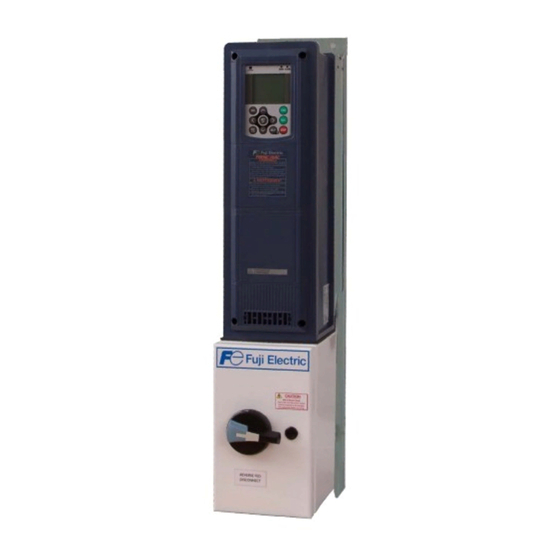
Safety Precautions Read this manual thoroughly before proceeding with installation, connections (wiring), or maintenance and inspection. Ensure you have sound knowledge of the device and familiarize yourself with all safety information and precautions before proceeding to operate the drive. Refer to the FRENIC-HVAC drive Instruction Manual (INR-SI47- 1707c-JE) for further safety information. - Page 3 FRENIC-HVAC Combination VFD Overview The FRENIC-HVAC Combination VFD is a packaged drive solution in a UL Type 1 or Type 12 enclosure designed for indoor HVAC applications. Features • UL/NEMA Type 1 or Type 12 enclosure – “slim-type” design • Non-fusible input disconnect with padlockable through-the-door operator handle mechanically interlocked with the enclosure cover/door (motor branch circuit protection required and to be provided by others), also available is an optional input...
-
Page 4: Panel Identification
Panel Identification Each FRENIC-HVAC Combination VFD has a nameplate label, like the example pictured above, which contains important information about the panel. This label is located on the inside of the hinged door or cover of the enclosure. CAUTION • Refer to the nameplate label to determine the panel input voltage and current requirements prior to installation and wiring. -
Page 5: Installation
Installation CAUTION The FRENIC-HVAC Combination VFD should be located: • Away from flammable or combustible liquids, gases, and other materials • Away from sources of severe dust, metal shavings, or other particulate material • Away from corrosive liquids, spray, or mist •... - Page 6 Motor Branch Circuit Protection Additional Motor Branch Circuit Protection Maximum Amp Rating Rating & Type Required 208/230VAC, 60Hz, 3PH 10A - Class J Time-Delay Fuses 10A - Class J Time-Delay Fuses 15A - Class J Time-Delay Fuses 25A - Class J Time-Delay Fuses 30A - Class J Time-Delay Fuses 50A - Class J Time-Delay Fuses 70A - Class J Time-Delay Fuses...
-
Page 7: Wiring Overview
Wiring Overview The FRENIC-HVAC Combination VFD must be connected to an input power source, a motor (output power), ground, and control may be local or by using remote devices such as switches, potentiometers, etc…. WARNING • Wiring should be performed by a qualified electrician using standard practices as specified by local and national codes. - Page 8 Wiring Overview (cont’d) UL/NEMA Type 1 & 12 (Typical Wire Routing) Page 8 of 37...
- Page 9 Wiring Overview (cont’d) UL/NEMA Type 1 & 12 (Typical Wire Routing) Page 9 of 37...
- Page 10 Wiring Overview (cont’d) UL/NEMA Type 1 (Typical Wire Routing) Page 10 of 37...
- Page 11 Wiring Overview (cont’d) UL/NEMA Type 1 (Typical Wire Routing) Page 11 of 37...
- Page 12 Wiring Overview (cont’d) UL/NEMA Type 12 (Typical Wire Routing) Page 12 of 37...
- Page 13 Wiring Overview (cont’d) UL/NEMA Type 12 (Typical Wire Routing) Page 13 of 37...
- Page 14 Wiring Overview (cont’d) UL/NEMA Type 1 (Typical Wire Routing) Page 14 of 37...
- Page 15 Wiring Overview (cont’d) UL/NEMA Type 1 (Typical Wire Routing) Page 15 of 37...
- Page 16 Wiring Overview (cont’d) UL/NEMA Type 12 (Typical Wire Routing) Page 16 of 37...
- Page 17 Wiring Overview (cont’d) UL/NEMA Type 12 (Typical Wire Routing) Page 17 of 37...
- Page 18 Wiring Overview (cont’d) Power Wiring (Motor Leads) The customer power output (motor leads) wiring connects directly to the U, V, and W terminals on the drive. The following picture shows wiring connections that are available on FRENIC-HVAC drives: ** Note ** The enable jumpers (PLC to EN1 &...
-
Page 19: Control Wiring
Control Wiring All control wiring connects directly to the control terminal board on the drive. The following pictures show typical control wiring connections that are available on FRENIC- HVAC drives. Description of Control Connections • Analog speed reference input: o VFD terminals 11 & 12 for 0-10VDC OR o VFD terminals 11 &... - Page 20 • Run input: o VFD terminals CM & FWD Must be closed to run combination VFD • Enable input: o VFD terminals CM & X1 o Must be closed to run combination VFD • Fireman override input: o VFD Terminals CM & X2 o Can be programmed to provide manual override of the Run input, and motor overload relay, allowing the FRENIC-HVAC to operate in the event of an emergency...
- Page 21 • Drive Run output: o VFD terminals Y5A & Y5C for NO contacts rated for 0.3A @ 250VAC max & 0.5A @ 48VDC o Used for monitoring drive run status Common • Drive Fault output: o VFD terminals 30A & 30C for NO contacts rated for 0.3A @ 250VAC max & 0.5A @ 48VDC o VFD terminals 30B &...
- Page 22 Control Wiring (cont’d) Options • Damper Control output: o VFD relay card terminals 1A & 1C for NO contacts rated for 0.3A @ 250VAC max & 0.5A @ 48VDC o Used to control the position of a damper valve in coordination with drive operation Common •...
- Page 23 Field Wiring Torque and Wire Size Values for HVAC Combination VFD 208/230V Non-Fusible Disconnect Circuit Breaker Terminal Blocks 'DISC' 'CB' 'VFD Terminals' 31.9 lb.in 14-10 AWG 39.9 lb.in 8 AWG 26.5 lb.in 14-4 AWG 47.8 lb.in 6-3 AWG 55.7 lb.in 6.2 lb.in 2-1 AWG 18 AWG...
- Page 24 Field Wiring Torque and Wire Size Values for HVAC Combination 460V 'DISC' 'CB' 'VFD Terminals' 31.9 lb.in 14-10 AWG 39.9 lb.in 8 AWG 26.5 lb.in '14-4 AWG 47.8 lb.in 6-3 AWG 55.7 lb.in 2-1 AWG 6.2 lb.in 18 AWG 36.2 lb.in 14 AWG 39.8 lb.in 47.8 lb.in...
- Page 25 Field Wiring Torque and Wire Size Values for HVAC Combination 575V Non-Fusible Disconnect Circuit Breaker Terminal Blocks 'DISC' 'CB' 'VFD Terminals' 31.9 lb.in 14-10 AWG 39.9 lb.in 26.5 lb.in 8 AWG '14-4 AWG 47.8 lb.in 6-3 AWG 6.2 lb.in 55.7 lb.in 2-1 AWG 18 AWG 36.2 lb.in...
- Page 26 BASIC Combination VFD STARTUP CAUTION • Make sure all power and control wiring is completed before proceeding. • As with all electrical equipment installations, insure all safety/wiring instructions have been followed in accordance with this product’s manuals and local and national codes.
- Page 27 Setting up Local Control Also refer to the following section Programming the Combination VFD FRENIC-HVAC and the drive Instruction Manual (INR-SI47-1707c-JE) for more FRENIC-HVAC information. Combination VFD was intended to be integrated into a building FRENIC-HVAC automation system and controlled by remote signals. If these signals are not available, the combination VFD can be set up to be operated locally.
-
Page 28: Common Parameter Settings
COMMON PARAMETER SETTINGS Also refer to the FRENIC-HVAC drive’s User’s Manual (24A7-E-0069*) located on the CD provided as part of the documentation package for additional information. Factory-set drive parameters and settings These parameters and settings are pre-set from the factory for the combination VFD to be operational. - Page 29 Combination VFD Programming the FRENIC-HVAC Also refer to Chapter 5 in the FRENIC-HVAC drive’s User’s Manual (24A7-E-0069*) for more information. Page 29 of 37...
- Page 30 Programming the FRENIC-HVAC Combination VFD (cont’d) To set drive parameters using the keypad, first make sure the drive is stopped. Parameters cannot be changed while the drive is running. To enter the programming menu, press the Program Key (PRG) on the keypad. To return to the previous screen, press (RESET) or to completely exit programming from any menu press (PRG).
- Page 31 Function code settings can be changed using the (UP) and (DOWN) keys on the keypad. Pressing (SET) saves the changes, while pressing (RESET) discards the changes, and both return to the previous menu. The most frequently modified parameters can be accessed in the ‘Quick-Setup’ menu (item 0 on the programming menu screen).
-
Page 32: Operation
OPERATION Operator Controls includes the following controls for local operation FRENIC-HVAC Combination VFD and monitoring: • Main power Disconnect/Circuit Breaker • Drive keypad includes the following controls for remote operation FRENIC-HVAC Combination VFD and monitoring: • Analog speed reference input •... -
Page 33: Maintenance
MAINTENANCE Periodic Maintenance The following items require periodic inspection and maintenance: • Fans should be checked for proper operation and filters cleaned and/or replaced on a schedule that suits local ambient conditions. • Power wiring connections should be checked and re-torqued every six months. - Page 34 7.5-15Hp @ 208/230V & 15-30Hp @ 460V & 575V Remove this nut for ease of fan removal. Reinstall after servicing the fan and torque to 55-58 lb.in. Page 34 of 37...
- Page 35 20-25Hp @ 208/230V & 40-50Hp @ 460V & 575V • To replace the front cover of the VFD, #1 angle the bottom of the VFD faceplate at a 45 degree angle and place the front edge on the VFD and then #2 slide the cover down toward the gasket making sure not to damage the gasket.
- Page 36 • #3 with the bottom securely against the gasket, angle the top of the front cover onto the VFD and tighten the screws. Page 36 of 37...
-
Page 37: Troubleshooting
TROUBLESHOOTING FRENIC-HVAC Drive For drive-specific issues, refer to the FRENIC-HVAC drive instruction manual (INR-SI47- 1707c-JE). Motor Rotation • Problem: Motor turns in incorrect direction. Solution: Swap two of the three motor output connections. For Additional Support Please Call 1-888-900-3854 Page 37 of 37...
Need help?
Do you have a question about the FRENIC-HVAC Series and is the answer not in the manual?
Questions and answers