Table of Contents
Advertisement
Advertisement
Table of Contents

Related Manuals for Fuji Electric Alpha7 VV


Summary of Contents for Fuji Electric Alpha7 VV
- Page 2 This manual is "User's Manual for Fuji AC Servo System ALPHA7 Series". The user's manual is in one volume and covers all handling methods of the product. The following documents are included in the package of each device. Device Document name Doc.
- Page 4 CHAPTER 0 INTRODUCTION CHAPTER 1 INSTALLATION CHAPTER 2 WIRING CHAPTER 3 OPERATION CHAPTER 4 PARAMETER CHAPTER 5 SERVO ADJUSTMENT CHAPTER 6 KEYPAD CHAPTER 7 MAINTENANCE AND INSPECTION CHAPTER 8 SPECIFICATIONS CHAPTER 9 CHARACTERISTICS CHAPTER 10 PERIPHERAL EQUIPMENT CHAPTER 11 ABSOLUTE POSITION SYSTEM CHAPTER 12 POSITIONING DATA CHAPTER 13 MODBUS RTU COMMUNICATION CHAPTER 14 PC LOADER...
-
Page 5: Table Of Contents
Contents CHAPTER 0 INTRODUCTION 0.1 Safety Precautions ··································································· 0-2 ■ Precautions on use ··················································································· 0-3 ■ Precautions on storage ············································································· 0-4 ■ Precautions on transportation ····································································· 0-4 ■ Precautions on installation ········································································· 0-5 ■ Precautions on wiring ················································································ 0-6 ■ Precautions on operation ··········································································· 0-7 ■... - Page 6 1.2.3 Installing the Servo Amplifier ··················································· 1-9 1.2.4 Depth of Control Panel ························································ 1-11 CHAPTER 2 WIRING Configuration ······································································· 2-2 2.1.1 Part Name ·········································································· 2-2 2.1.2 Configuration ······································································· 2-5 2.1.3 Sequence I/O ···································································· 2-10 2.1.3.1 Pulse Input (PPI, CA, *CA, CB, *CA) ················································ 2-12 2.1.3.2 Pulse Output (FFA, *FFA, FFB, *FFB, FFZ, *FFZ) ······························...
- Page 7 Interrupt input: Sequence input signal (Reference value 49) ····························· 2-36 Over-travel in positive direction [+OT]: Sequence input signal (Reference value 7) ·················································· 2-39 Over-travel in negative direction [-OT]: Sequence input signal (Reference value 8) ·················································· 2-39 Forced stop [EMG]: Sequence input signal (Reference value 10) ······················ 2-41 Alarm reset [RST]: Sequence input signal (Reference value 11) ························...
- Page 8 Multi-step speed selection [X1]: Sequence input signal (Reference value 51) ······· 2-65 Multi-step speed selection [X2]: Sequence input signal (Reference value 52) ······· 2-65 Multi-step speed selection [X3]: Sequence input signal (Reference value 53) ······· 2-65 Free-run [BX]: Sequence input signal (Reference value 54) ····························· 2-66 Edit permission: Sequence input signal (Reference value 55) ···························...
- Page 9 Edit permission response: Sequence output signal (Reference value 29) ············ 2-88 Data error: Sequence output signal (Reference value 30) ································ 2-89 Address error: Sequence output signal (Reference value 31) ··························· 2-89 Alarm code 0: Sequence output signal (Reference value 32) ···························· 2-90 Alarm code 1: Sequence output signal (Reference value 33) ····························...
- Page 10 CONTb Through: Sequence output signal (Reference value 92) ······················ 2-104 CONTc Through: Sequence output signal (Reference value 93) ······················· 2-104 CONTd Through: Sequence output signal (Reference value 94) ······················ 2-104 CONTe Through: Sequence output signal (Reference value 95) ······················ 2-104 Connection Example to Host Controller ·······························...
- Page 11 3.4.6 Homing ·········································································· 3-16 3.4.7 Interrupt Positioning ························································· 3-17 3.4.8 Torque Limit ··································································· 3-19 3.4.9 Positioning Data Operation ················································ 3-20 3.4.10 Immediate Value Data Operation ········································· 3-21 3.4.11 Interrupting/Stopping Operation ·········································· 3-22 CHAPTER 4 PARAMETER 4.1 Parameter Division ·································································· 4-2 4.2 Basic Parameters ····································································...
- Page 12 PA1_36 to 40 Acceleration / deceleration selection at speed control, Acceleration time and deceleration time settings ············································ 4-27 PA1_41 to 47 Manual feed speed 1 to 7/speed limit 1 to 7 for torque control ····· 4-29 4.3 Control Gain and Filter Setting Parameters ······························· 4-30 4.3.1 List (PA1_) ··································································...
- Page 13 PA2_15 Deceleration operation for creep speed ·········································· 4-50 PA2_16 Home position after homing completion ········································· 4-51 PA2_17 Home position detection range ····················································· 4-51 PA2_18 Deceleration time at OT during homing ·········································· 4-52 PA2_22 Detection time for contact-stopper PA2_23 Torque limit for contact-stopper ······················································ 4-52 PA2_24 Selection of operation at OT during homing ····································...
- Page 14 PA2_78 Display transition at warning detection ··········································· 4-93 PA2_80 to 85 Parameter in RAM 1 to 6 ····················································· 4-94 PA2_86 to 88 Positioning data in RAM 1 to 3 ·············································· 4-94 PA2_89 and 90 Sequence test mode: Mode selection and encoder selection ···· 4-95 PA2_93 Parity/stop bit selection (for Modbus) ·············································...
- Page 15 4.8.1 List (PA4_) ································································ 4-117 4.8.2 Description of Each Parameter ············································ 4-119 PA4_01 to 06 Interference detection function settings ····································· 4-119 PA4_10 Enable/disable SEMI F47 compatible function ······································ 4-120 PA4_11 to 12 Function safety operation settings ············································ 4-121 PA4_21 Torque control speed limit method ················································· 4-123 PA4_51 to 59 Notch filter settings ·······························································...
- Page 16 5.7.1 Conditions for Interpolation Control Mode ································ 5-21 5.7.2 Parameters Used for Interpolation Control Mode ······················· 5-21 5.7.3 Adjustment Procedure in Interpolation Control Mode ·················· 5-22 5.8 Profile Operation ··································································· 5-23 5.8.1 What is Profile Operation? ···················································· 5-23 5.8.2 Description of Operation ······················································ 5-25 5.9 Special Adjustment (Vibration Suppression) ·····························...
- Page 17 CHAPTER 8 SPECIFICATIONS 8.1 Specifications of Servomotor ···················································· 8-2 8.1.1 GYS Motor ·········································································· 8-2 8.1.2 GYB Motor ·········································································· 8-6 8.1.3 GYG Motor ········································································· 8-8 8.2 Specifications of Servo Amplifier ············································· 8-10 8.2.1 Common Specifications ······················································· 8-10 8.2.2 VV Type Specifications ························································ 8-12 8.3 Dimensions of Servomotor ·····················································...
- Page 18 CHAPTER 10 PERIPHERAL EQUIPMENT 10-1 10.1 Overall Configuration of Peripheral Equipment ························ 10-2 10.2 Cable Size ··········································································· 10-3 10.2.1 Main Circuit Section Cable Size ··········································· 10-4 10.2.2 Encoder Cable ································································· 10-5 10.2.3 How to Calculate the Servo Amplifier Input Current ·················· 10-6 10.2.4 Conditions for Selecting Peripheral Equipment of Servo Amplifier ······································································...
- Page 19 Encoder relay cable with battery ······························································· 10-35 Encoder cable with battery (1) ·································································· 10-36 Encoder cable with battery (2) ·································································· 10-37 Encoder cable with battery (3) ·································································· 10-38 Encoder cable with battery (4) ·································································· 10-39 Encoder cable with battery (5) ·································································· 10-40 Battery case kit for encoder cable ······························································...
- Page 20 12.3 Startup ············································································· 12-13 12.4 Setting Change ·································································· 12-16 12.5 Response Time ·································································· 12-16 CHAPTER 13 MODBUS RTU COMMUNICATION 13-1 13.1 Settings for Servo Amplifier ·················································· 13-2 13.2 Communication Specifications ·············································· 13-6 13.3 Transmission Protocol ························································· 13-7 13.3.1 Message types ································································· 13-7 13.3.2 Message fields ·································································...
- Page 21 14.5.9 Changing the Language ··················································· 14-34 CHAPTER 15 STANDARDS COMPLIANCE 15-1 15.1 European Standards Compatibility ( ) ······························· 15-2 15.1.1 Compatibility with EMC Standards ········································ 15-3 15.1.2 Compatibility with European Low Voltage Directive ·················· 15-4 15.2 UL Standards and Canadian Standards (cUL Certification) Compliance ···············································································...
-
Page 22: Chapter 0 Introduction
CHAPTER 0 INTRODUCTION... -
Page 23: Safety Precautions
CHAPTER 0 INTRODUCTION 0.1 Safety Precautions (1) Types and meanings of warning signs Before starting installation, wiring work, maintenance or inspection, read through this manual and other attached documents. Be familiar with the device, safety information and precautions before using. In this manual, safety precautions are described in two categories: "WARNING"... -
Page 24: Precautions On Use
CHAPTER 0 INTRODUCTION ■ Precautions on use WARNING Do not touch the inside of the servo amplifier. There is a risk of electric shock. Make sure to ground the grounding terminal of the servo amplifier and servomotor. There is a risk of electric shock. ... -
Page 25: Precautions On Storage
CHAPTER 0 INTRODUCTION ■ Precautions on storage CAUTION Do not store at places susceptible to rain or water splashes or toxic gases or liquid. It might cause failure. Store at places without direct sunshine within the predetermined temperature and humidity range (between -20 [°C] and +60 [°C] , between 10 [%] and 90 [%] RH, without condensation). -
Page 26: Precautions On Installation
CHAPTER 0 INTRODUCTION ■ Precautions on installation CAUTION Do not ride on the servomotor or place a heavy matter on it. It might cause failure, breakage, electric shock and injuries. Do not block the exhaust port or do not allow foreign substance to enter. It might cause fire and electric shock. -
Page 27: Precautions On Wiring
CHAPTER 0 INTRODUCTION ■ Precautions on wiring CAUTION Never apply the commercial power supply to the U, V and W terminals of the servomotor. It might cause fire and failure. Do not connect the grounding (E) cable to the U, V and W terminals of the servomotor. Do not connect the U, V and W terminals in inappropriate order. -
Page 28: Precautions On Operation
CHAPTER 0 INTRODUCTION ■ Precautions on operation CAUTION In order to avoid unstable motions, never change adjustment radically. It might cause injuries. To perform test operation, fix the servomotor and leave it disconnected from the mechanical system. After checking the motion, connect to the machine. Otherwise, it might cause injuries. -
Page 29: General Precautions
CHAPTER 0 INTRODUCTION ■ General precautions CAUTION Drawings in this manual may show the state without covers or shields for safety to explain in details. Restore the covers and shields in the original state when operating the product. In case of disposal of the product, comply with the following two laws and act in accordance with each regulation. -
Page 30: Compliance With Eu Directives
CHAPTER 0 INTRODUCTION ■ Compliance with EU directives EU directives aim at integration of regulations among the EU member countries to promote distribution of safety assured products. It is required to satisfy basic safety requirements including machine directive (2006/42/EC), EMC directive (2014/30/EU), and low voltage directive (2014/35EU) and affix a CE mark (CE marking) on the product sold in EU member countries. -
Page 31: Outline Of System
CHAPTER 0 INTRODUCTION 0.2 Outline of System ALPHA 7 Series is an AC servo system that supports various host interfaces and realizes the best motion control for the target machine. 0.2.1 Servomotor Three types of servomotor are available; an ultra-low inertia type (GYS), and two medium inertia types (GYG/GYB). -
Page 32: Servo Amplifier
CHAPTER 0 INTRODUCTION 0.2.2 Servo Amplifier General-purpose interface type (VV) and high-speed serial bus type (VS, LS) servo amplifiers are available (high-speed serial bus type servo amplifiers are Fuji's SX-bus compatible products). Control mode Command Applicable Model Power supply Capacity Type Positioning interface... -
Page 33: Model Nomenclature
CHAPTER 0 INTRODUCTION 0.3 Model Nomenclature When unpacking Check the following items. Check if the delivered item is what you have ordered. Check if the product is damaged during transportation. Check if the instruction manual is included. If you have any uncertainties, contact the seller. - Page 34 CHAPTER 0 INTRODUCTION 0.3.2 Servo Amplifier Rating plate (servo amplifier) Model nomenclature (servo amplifier) The model and serial number are also marked on the 2 0 1 F 7 V V 2 front panel of the main body of the servo amplifier. Digit Specification Code...
-
Page 35: Servo Amplifier
CHAPTER 0 INTRODUCTION 0.4 Combination between Servomotor and Servo Amplifier 0.4.1 VV Type Use the servomotor and servo amplifier in one of the following sets. Do not use in other sets. Applicable motor Applicable motor GYS motor GYB motor medium GYB motor GYB motor ultra-low inertia... -
Page 36: Chapter 1 Installation
CHAPTER 1 INSTALLATION... -
Page 37: Servomotor
CHAPTER 1 INSTALLATION 1.1 Servomotor 1.1.1 Storage Environment Select the following environment when storing the servomotor, or when resting the machine under the state without power distribution. Item Environmental condition Ambient temperature -20 [°C] to +60 [°C] (no freezing allowed) Ambient humidity 10 [%] to 90 [%] RH (no condensation allowed) 1.1.2 Operating Environment... -
Page 38: Installing The Servomotor
40-degree or less. Install a cover in environments susceptible to much water, oil or AC SERVO MOTOR oil mist. Fuji Electric FA Do not operate with cables immersed in oil. YM 539189 - 1 JAPAN Some coolant types can provide on sealant, cable, case or similar. -
Page 39: Servomotor Handling Precautions
CHAPTER 1 INSTALLATION 1.1.5 Servomotor Handling Precautions Do not hammer Do not give a strong impact on the output shaft of the servomotor. Otherwise the encoder inside the motor will be broken. Align the center when connecting with the machine system. Use a flexible coupling. Use rigid one designed exclusively for servomotors whenever possible. -
Page 40: Assembling Accuracy
CHAPTER 1 INSTALLATION 1.1.7 Assembling Accuracy The assembling accuracy of the servomotor is shown below. Unit: [mm] Runout at shaft Misalignment Perpendicularity of Servomotor model (flange) flange face GYSD7 GYG7 Within 0.02 Within 0.06 Within 0.08 GYBD7 Runout at shaft end Misalignment (flange) Perpendicularity of flange face Servomotor... -
Page 41: Allowable Load
Radial load Thrust load the shaft end Motor model Radial load (Fr) Fr[N] Fs[N] LR[mm] GYS500D7-2 GYS101D7-2 AC SERVO MOTOR Thrust Fuji Electric FA load GYS201D7-2 YM539189-1 JAPAN (Fs) GYS401D7-2 GYS751D7-2 Servomotor at the shaft end (LR) GYS102D7-2 GYS152D7-2 GYG102C7-2 GYG851B7-2... -
Page 42: Servo Amplifier
CHAPTER 1 INSTALLATION 1.2 Servo Amplifier 1.2.1 Storage Environment Select the following environment when storing the servo amplifier, or when resting the machine under the state without power distribution. Item Environmental condition Ambient temperature -20 [°C] to +80 [°C] (no freezing allowed) Ambient humidity 10 [%] to 90 [%] RH (no condensation allowed) Indoors at altitude ≤... -
Page 43: Operating Environment
CHAPTER 1 INSTALLATION 1.2.2 Operating Environment Operate the servo amplifier in the following environment. The servo amplifier is neither dust proof nor water proof. Item Environmental condition Ambient temperature -10 [°C] to +55 [°C] (no freezing allowed) Ambient humidity 10 [%] to 90 [%] RH (no condensation allowed) Indoors at altitude ≤... -
Page 44: Installing The Servo Amplifier
CHAPTER 1 INSTALLATION 1.2.3 Installing the Servo Amplifier (1) Install the servo amplifier vertically to the ground so that the "ALPHA7" characters (see the arrow in the figure on the right) on the front panel of the servo amplifier is horizontal. Use M4 screws with length between 12 and 20 mm for the mounting to the control panel. - Page 45 CHAPTER 1 INSTALLATION (4) To suppress rises in servo amplifier temperature, secure the interval shown in the following diagram between servo amplifiers and from peripheral equipment. 10[mm] or more 10[mm] or more 50[mm] or more 5[mm] or more 40[mm] 5[mm] or more or more 1-10 Servo Amplifier...
-
Page 46: Depth Of Control Panel
CHAPTER 1 INSTALLATION 1.2.4 Depth of Control Panel Reserve 80 [mm] or a wider space in front of the servo amplifier which is connected with sequence I/O cables and encoder cable. Main power connector Sequence cable Encoder cable 80 [mm] Amplifier depth 1-11 Servo Amplifier... - Page 47 CHAPTER 1 INSTALLATION 1-12 Servo Amplifier...
-
Page 48: Chapter 2 Wiring
CHAPTER 2 WIRING... -
Page 49: Configuration
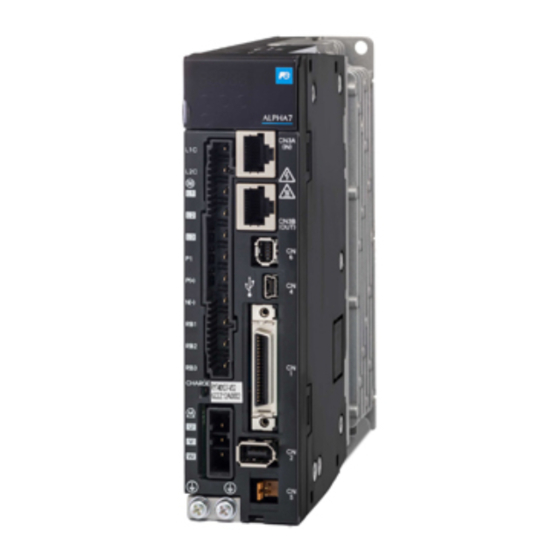
CHAPTER 2 WIRING 2.1 Configuration 2.1.1 Part Name Servomotors GYS, GYB (lead wire specification): 0.75kW or less GYB (connector connection specification): 0.75kW or less A V O ID S H A R P IM P A C T T O S H A F T QR... - Page 50 CHAPTER 2 WIRING Servo amplifier (frame 1) 0.4kW or less Keypad 5-digit 7-segment LED, 4 keys, monitor terminal Analog monitor (CN7) Monitors analog waveforms. RS-485 (CN3A (IN), CN3B (OUT)) Upper side lower side CN3A, CN3B Power supply (TB1) Safety device connection ・Control power supply connector (CN6) ・Motor power supply...
- Page 51 CHAPTER 2 WIRING Servo amplifier (frame 2) Keypad 5-digit 7-segment LED, 4 keys, monitor terminal, 1 Analog monitor (CN7) Monitors analog waveforms. RS-485 (CN3A (IN), CN3B (OUT)) Upper side CN3A, lower side CN3B Power supply (TB1) Safety device connection ・Control power supply connector (CN6) ・Motor power supply...
-
Page 52: Configuration
CHAPTER 2 WIRING 2.1.2 Configuration The figure on page 2-6 shows the general configuration of devices. There is no need to connect all devices. The size on each device in the figure is not drawn at the uniform scale. (same as other chapters) ... - Page 53 CHAPTER 2 WIRING For servo amplifier frames 1 For lead wire type motors, connect cables as shown below. MCCB/ELCB Computer (commercially available product) AC reactor Loader software can be downloaded free of charge. Power filter General-purpose PLC (USB) Servo amplifier PC controller (L1C, L2C) RS-485...
- Page 54 CHAPTER 2 WIRING Connection Diagram (Servo amplifier frame 1) Connect the external regenerative resistor across RB1 and RB2. (Remove the short wire In case of commercial P(+) N(-) from RS2-RB3.) power supply single-phase 200V input, connect across L1 and L2 U...
- Page 55 CHAPTER 2 WIRING For servo amplifier frames 2 (except for 751D7 in frame 2) For Cannon connector type motors, connect cables as shown below. MCCB/ELCB Computer (commercially available product) Loader software can be downloaded free of charge. AC reactor General-purpose PLC Power filter (USB) PC controller...
- Page 56 CHAPTER 2 WIRING Connection Diagram (Servo amplifier frame 2) Connect the external regenerative resistor across RB1 and RB2. (Remove the short wire In case of commercial P(+) N(-) power supply single-phase from RB2-RB3.) 200V input, connect across L1 and L2 terminals.
-
Page 57: Sequence I/O
CHAPTER 2 WIRING 2.1.3 Sequence I/O The wiring connector is not included in the servo amplifier. Connector kit type: WSK-D36P VREF TREF MON1 *FFA MON2 *FFB *FFZ OUT3 OUT4 OUT5 CONT7 CONT8 OUT1 OUT2 CONT1 CONT2 CONT5 CONT6 19 COMOUT 20 COMIN CONT3 CONT4... - Page 58 CHAPTER 2 WIRING Terminal Function symbol CONT1 CONT2 Sequence input (For sink/source) CONT3 Supply command signals to the servo amplifier through these terminals. CONT4 12 to 24 [V] DC/approx. 8[mA] (per point). CONT5 Photo coupler isolated. The reference potential is the COMIN terminal. CONT6 (Soft filter 0.5 [ms], agreement of two scans, except for interrupt input) CONT7...
-
Page 59: Pulse Input (Ppi, Ca, *Ca, Cb, *Ca)
CHAPTER 2 WIRING 2.1.3.1 Pulse Input (PPI, CA, *CA, CB, *CA) Pulse input terminal Format: Command pulse/direction, forward/reverse pulse, A/B phase pulse (parameter switch) Max. input frequency: 4[MHz] (differential input), 200[kHz] (open collector input) The 90° phase difference 2 signal is the frequency after multiplying by four. It is normally a multiple of four. -
Page 60: Pulse Output (Ffa, *Ffa, Ffb, *Ffb, Ffz, *Ffz)
CHAPTER 2 WIRING The pulse input terminals can be used as a CONT input by changing the parameter (PA3_48, PA3_49). <24 [V] DC input> Servo amplifier 1kΩ, 1W CA(CB) DC24V *CA(*CB) <12 [V] DC input> Servo amplifier 470Ω, 1W CA(CB) DC12V *CA(*CB) -
Page 61: Analog Input (Vref [ Tref], [P10] M5)
CHAPTER 2 WIRING 2.1.3.4 Analog Input (VREF [ TREF], [P10] M5) The analog input is the terminal used for speed/torque control by the analog command. Input voltage: 0 to ±10 [V] DC Variable resistor: 1 to 5 kΩ (1/2 W) ... -
Page 62: Analog Monitor Output (Mon1, Mon2, M5)
CHAPTER 2 WIRING 2.1.3.5 Analog Monitor Output (MON1, MON2, M5) The analog monitor output is the analog voltage output terminal of the servo amplifier. The output is specified with a parameter. Observe after 2 seconds or longer have elapsed since turning ON the power. The output voltage will be unstable immediately after turning ON the power, and after turning OFF the power. -
Page 63: Sequence Output (Out1, Out2
CHAPTER 2 WIRING 2.1.3.7 Sequence Output (OUT1, OUT2, ... COMOUT) These are output terminals for sequence control. They are compatible with both sink output and source output. Use in the 30 [V] DC/50[mA] range. Terminal functions are set with parameters. Refer to “2.5.3 Signal Descriptions”... -
Page 64: Usb (Cn4)
CHAPTER 2 WIRING 2.1.5 USB (CN4) USB-miniB type 4-pin connector. Use a marketed cable. 2.1.6 Safety Function (CN6) This is a safety stop function (STO) regulated by EN60204-1 Stop Category 0. The motor is slowly stopped (free-run stop) by turning OFF [EN1+] and [EN2+] inputs. ... -
Page 65: P-N Junction
CHAPTER 2 WIRING 2.2 P-N Junction Connect the DC intermediate voltages of two servo amplifiers directly to facilitate power transfer. By doing so, power can be supplied by the regenerative side (brake side) servo amplifier to the powering side (drive side) servo amplifier, allowing overall power consumption to be reduced. Application examples ... -
Page 66: Servomotor
CHAPTER 2 WIRING 2.3 Servomotor There are wiring of the main body of the servomotor and that of the brake (servomotor equipped with a brake). CAUTION Keep consistency in the phase order between the servomotor and servo amplifier. Do not connect commercial power to the servomotor. Otherwise it may cause failure. 2.3.1 Motor Power Connectors Connector kit models: WSK-M04P-E (GYS model 0.75kW or less/GYB model lead wire specification servomotor side) -
Page 67: Brake Connector
CHAPTER 2 WIRING 2.3.2 Brake Connector Connector kit type: WSK-M02P-E (GYS model: 0.75kW or less/GYB model: lead wire specification servomotor side) Connector terminal symbol The brake of the servomotor equipped with a brake is a non-exciting brake. To turn the servomotor, +24 [V] must be supplied. -
Page 68: Encoder
CHAPTER 2 WIRING 2.4 Encoder 2.4.1 Encoder Wiring Cable Connector kit models: WSK-P09P-D (GYS model: 0.75kW or less/GYB model: lead wire specification servomotor side) WSK-P06P-C (GYS model: 1.0 to 1.5kW servomotor side) WSK-P06P-J (GYG model: 1.0 to 1.5kW servomotor side) Connector terminal symbol Application range... - Page 69 CHAPTER 2 WIRING Shield cables (twisted pair type) GYS model/GYB model lead wire specification 30V 80°C UL VW-1 AWG#25/2P + AWG#22/2C or AWG#23/3P shielded cable (For wiring length of 10 m or shorter) 30V 80°C UL VW-1 AWG#25/2P + AWG#17/2C shielded cable or equivalent (For wiring length >...
-
Page 70: Encoder Cable Fabrication Method
CHAPTER 2 WIRING 2.4.2 Encoder Cable Fabrication Method To fabricate the encoder cable by yourself, take care of the following. Do not install a relaying terminal block between the servo amplifier and motor. Use a shielded cable. Connect the shielded cable with the designated connector pin, connector shell or cable clamp on both sides. -
Page 71: Encoder Cable With Battery Fabrication Method
CHAPTER 2 WIRING Solder the wiring to the connector. Fitting a shrinkable tube to each wire ensures safety. Fit the shell body to the connector. Align the shell cover with the clips on both sides of the shell body and attach. Fit the cable clamp to the assembled shell, and secure with the screws. - Page 72 CHAPTER 2 WIRING [3] Wrap vinyl tape 2 to 3 times around approximately 10 mm of the base of the braided wire for insulation. Vinyl tape [4] Wrap the battery board wiring 2 to 3 times around the shield wire, and pass through the thermal contraction Battery board wiring Thermal contraction tube tube.
- Page 73 CHAPTER 2 WIRING [16] Connect the battery to CN4. Battery [17] Store the battery in battery case (A). [18] Hook battery case (B) onto the shaft, and secure by aligning the clips at 2 locations. Battery case (B) Shaft [Complete] 2-26 Encoder...
- Page 74 CHAPTER 2 WIRING Encoder cable wire size Servo amplifier Servomotor P5 1 M5 2 BAT + 3 BAT+ BAT- 4 BAT- SIG + 5 SIG+ SIG- 6 SIG- Shell Servo Lead wire diameter Signal amplifier side Motor side Wiring length 10 m or Wiring length between name Connector...
-
Page 75: Description Of I/O Signals
CHAPTER 2 WIRING 2.5 Description of I/O Signals 2.5.1 List of input signals Specify the signals to be assigned to sequence input terminals by using parameters. Default Name Setting range Change value PA03_01 CONT1 signal assignment PA03_02 CONT2 signal assignment PA03_03 CONT3 signal assignment PA03_04 CONT4 signal assignment PA03_05 CONT5 signal assignment... -
Page 76: List Of Output Signals
CHAPTER 2 WIRING Position preset Override enable Gain switch Override 1 Positioning data selection Torque limit 0 Override 2 Broadcast cancel Torque limit 1 Override 4 Immediate value Override 8 continuation Immediate value change Interrupt input enable Electronic gear numerator Interrupt input selection 0 Electronic gear numerator... - Page 77 CHAPTER 2 WIRING Cycle end detection Forced stop detection Interrupt positioning detection Interference detection Homing completion Battery warning Functional safety SS1 Zero deviation Life warning Functional safety SLS Zero speed CONTa Through Speed coincidence CONTb Through Torque limit detection CONTc Through Overload warning CONTd Through Servo control ready...
-
Page 78: Signal Descriptions
CHAPTER 2 WIRING 2.5.3 Signal Descriptions Input signal Servo-on [S-ON]: Sequence input signal (Reference value 1) The signal makes the servomotor ready to rotate. Function The servomotor is ready to rotate while the servo-on [S-ON] signal remains turned on. When the servo-on signal is turned off, the gate for IGBT is turned off and the servomotor does not rotate. -
Page 79: Forward Command [Fwd]: Sequence Input Signal (Reference Value 2)
CHAPTER 2 WIRING Forward command [FWD]: Sequence input signal (Reference value 2) Reverse command [REV]: Sequence input signal (Reference value 3) The signal makes the servomotor keep running while it remains turned on. Function The servomotor keeps rotating in the positive (negative-) direction while the forward command [FWD] (reverse command [REV]) signal remains turned on. - Page 80 CHAPTER 2 WIRING (2) Position control In the position control mode, only pulse inputs are accepted. To perform manual operation under position control, specify "6" to PA1_01 (control mode selection) and, while leaving the position control (37) signal turned on, turn the forward command [FWD] (or reverse command [REF]) signal on.
-
Page 81: Start Positioning [Start]: Sequence Input Signal (Reference Value 4)
CHAPTER 2 WIRING Start positioning [START]: Sequence input signal (Reference value 4) Positioning motion is executed according to positioning data or immediate value data sent via RS-485 communications. This function is enabled only if parameter PA1_01 is “7” (positioning operation). ... - Page 82 CHAPTER 2 WIRING Relevant description (1) Internal positioning data selection Set this parameter enable when performing positioning according to the positioning data. If 0 (disable) is set, immediate value data operation with RS-485 (Modbus communication) will be performed. Name Setting range Default value Change...
-
Page 83: Homing [Org]: Sequence Input Signal (Reference Value 5)
CHAPTER 2 WIRING Homing [ORG]: Sequence input signal (Reference value 5) Homing position LS [LS]: Sequence input signal (Reference value 6) Interrupt input: Sequence input signal (Reference value 49) A homing motion is executed and the home position is determined. This signal is enabled only when parameter PA1_01 (control mode selection) is set to "6"... - Page 84 CHAPTER 2 WIRING (5) The in-position signal is turned on with the stopping position being home position after homing completion PA2_16. In addition, the homing completion signal is turned on. To perform homing, use up positive over-travel [+OT] and negative over-travel [-OT] signals to assure safety.
- Page 85 CHAPTER 2 WIRING (9) A travel occurs first at the homing speed by the reverse traveling unit amount for homing. Thereafter the motion (1) to (5) described above is executed. Reference signal for shift operation (PA2_11) In regular cases, a travel occurs by the home position shift unit amount in reference to the encoder Z-phase signal.
-
Page 86: Sequence Input Signal (Reference Value 7)
CHAPTER 2 WIRING Over-travel in positive direction [+OT]: Sequence input signal (Reference value 7) Over-travel in negative direction [-OT]: Sequence input signal (Reference value 8) A signal from a limit switch or similar can forcibly stop the machine travel. Function The signal is an input from a limit switch for avoiding over-travel (OT) beyond the limit of machine travel. - Page 87 CHAPTER 2 WIRING (2) Output signal: +OT detection (38), -OT detection (39), OT detection (20) The +OT detection and -OT detection signals indicate that the servo amplifier detects the limit of travel in the mechanical system. A sequence output signal to the host controller can be notified the fact of detecting the +OT or -OT signal.
-
Page 88: Forced Stop [Emg]: Sequence Input Signal (Reference Value 10)
CHAPTER 2 WIRING Forced stop [EMG]: Sequence input signal (Reference value 10) Used to forcibly stop the servomotor. Function (1) Forced stop The servomotor is forcibly stopped while the forced stop [EMG] signal remains turned off. This signal is enabled in all control modes and it is given the highest priority. Because the safety and detection speed are significant, the forced stop signal is generally connected to the servo amplifier directly. -
Page 89: Alarm Reset [Rst]: Sequence Input Signal (Reference Value 11)
CHAPTER 2 WIRING Alarm reset [RST]: Sequence input signal (Reference value 11) The alarm reset signal resets alarm detection of the servo amplifier. Function The sequence input signal resets alarm detection of the servo amplifier. The rising edge of the alarm reset [RST] signal resets alarm detection. By starting the test operation mode at the keypad, operating the PC Loader or turning the power on again, the alarm can be reset. -
Page 90: Acc0: Sequence Input Signal (Reference Value 14)
CHAPTER 2 WIRING ACC0: Sequence input signal (Reference value 14) ACC0 switches the acceleration/deceleration time. Function (1) Acceleration/deceleration time switch The acceleration time and deceleration time of the servomotor follow the setting of PA1_37 to 40 (acceleration time, deceleration time). The acceleration time and deceleration time can be set separately. -
Page 91: Position Preset: Sequence Input Signal (Reference Value 16)
CHAPTER 2 WIRING Position preset: Sequence input signal (Reference value 16) The present command position and feedback position are preset (overwritten). Function The present command position and the present feedback position are made the reference value of PA2_19 (preset position) at the rising edge. However, the deviation is subtracted from the feedback position. -
Page 92: Gain Swtich: Sequence Input Signal (Reference Value 17)
CHAPTER 2 WIRING Gain swtich: Sequence input signal (Reference value 17) To switch the gain (response capability) of the servo system. Function When PA1_61 (gain changing factor) is set at "3" (external switch: CONT signal), the CONT signal assigned to this function switches the gain of the servo system. The control gain parameters that are enabled with the gain switch are listed in the table below. -
Page 93: Torque Limit 0: Sequence Input Signal (Reference Value 19)
CHAPTER 2 WIRING Torque limit 0: Sequence input signal (Reference value 19) Torque limit 1: Sequence input signal (Reference value 20) Limitations are set on the output torque of the servomotor. Function Limitation on the output torque of the servomotor by turning on the torque limit signal can be set. Specify the torque limit in increments of 1 [%] in the range from "0"... - Page 94 CHAPTER 2 WIRING Torque limit under torque control The limit [2] is always enabled. Deviation hold selection at torque limit Use deviation hold selection at torque limit (PA2_59) under position control to select the torque limit for retaining the deviation amount. Torque limit Torque limit Torque limit...
-
Page 95: Immediate Value Continuation: Sequence Input Signal (Reference Value 22)
CHAPTER 2 WIRING Immediate value continuation: Sequence input signal (Reference value 22) Positioning motion can be continued according to the next data from the target position (speed) started in the immediate value mode. This signal is enabled only when parameter PA1_01 (control mode selection) is set to "7" (positioning function). - Page 96 CHAPTER 2 WIRING Parameter setting To assign the immediate value continuation command to a sequence input terminal, specify the corresponding value ("22") to the input terminal function setting parameter. Relevant signal reference values include following. Assigned signal Immediate value continuation: sequence input signal Immediate value continuation completion: sequence output signal...
-
Page 97: Immediate Value Change: Sequence Input Signal (Reference Value 23)
CHAPTER 2 WIRING Immediate value change: Sequence input signal (Reference value 23) The target position and target speed of immediate data start can be changed at an arbitrary timing. This signal is enabled only when parameter PA1_01 (control mode selection) is set to "7" (positioning function). -
Page 98: Electronic Gear Numerator Selection
CHAPTER 2 WIRING Relevant description (1) Change setting completion The signal is turned on after the changing process is executed according to the immediate value change signal, and it is turned off after the immediate value change command is turned off. (2) Command position / command speed / ABS/INC Each piece of data can be changed arbitrarily. -
Page 99: Command Pulse Inhibit: Sequence Input Signal (Reference Value 26)
CHAPTER 2 WIRING Command Pulse inhibit: Sequence input signal (Reference value 26) The pulse input in the position control mode is enabled or disabled. Function The command pulse is not accepted while the command pulse inhibit signal remains turned on. ... -
Page 100: Proportional Control: Sequence Input Signal (Reference Value 29)
CHAPTER 2 WIRING Proportional control: Sequence input signal (Reference value 29) Proportional band control is adopted as a servo amplifier control method. Function With [S-ON] signal turned on, the signal will be turned on while the servomotor shaft is mechanically locked. -
Page 101: Positioning Cancel: Sequence Input Signal (Reference Value 32)
CHAPTER 2 WIRING Relevant description (1) Positioning cancel If positioning cancel (32) is executed while the pause (31) signal remains turned on, the positioning motion is canceled. (2) ABS/INC (positioning data) After the pause (31) signal is turned off, the remaining motion continues without relations to the absolute (ABS) or incremental (INC) mode of positioning data. -
Page 102: Teaching: Sequence Input Signal (Reference Value 35)
CHAPTER 2 WIRING Teaching: Sequence input signal (Reference value 35) The current position of the servomotor is written as position data in the positioning data. Function The current command position of the servomotor is written as position data in the positioning data at the activating edge of the teaching signal. -
Page 103: Control Mode Selection: Sequence Input Signal (Reference Value 36)
CHAPTER 2 WIRING Control mode selection: Sequence input signal (Reference value 36) To switch the control mode. Function This function is to be used to switch to the control mode (control state) during servomotor operation or similar. Turn the control mode selection signal, which is assigned to a CONT input signal, on or off to switch the control mode. - Page 104 CHAPTER 2 WIRING Parameter setting To assign position control to a sequence input terminal, specify the corresponding value ("37") to the input terminal function setting parameter. For command pulse ratio 1, specify ("27"), while specify ("28") for command pulse ratio 2. This signal is handled to be always turned off if it is not assigned to the sequence input signal.
- Page 105 CHAPTER 2 WIRING The conditions for enabling position control with the command pulse input are shown below. Servo-on [S-ON] = ON Forced stop [EMG] = ON (Control output ready for servo-on [RDY] = ON) Position control (37) = ON The command pulse is enabled while command pulse ratio 1 (27) or command pulse ratio 2 (28) remains turned on.
-
Page 106: Torque Control: Sequence Input Signal (Reference Value 38)
CHAPTER 2 WIRING Torque control: Sequence input signal (Reference value 38) This signal is enabled only when parameter PA1_01 (control mode selection) is set to "6" (extension mode). Function Turn on to conduct torque control in the extension mode. The servo amplifier is in the torque control mode while the torque control signal assigned to a CONT input signal remains turned on. - Page 107 CHAPTER 2 WIRING Relevant description (1) Maximum rotation speed If there is no load connected to the servomotor, the rotation speed is subject to a limitation on PA1_26 (maximum rotation speed (for torque control)) with a variation of about ±100 [r/min] (due to lack of speed control).
-
Page 108: Override Enable: Sequence Input Signal (Reference Value 43)
CHAPTER 2 WIRING Override enable: Sequence input signal (Reference value 43) Override 1: Sequence input signal (Reference value 44) Override 2: Sequence input signal (Reference value 45) Override 4: Sequence input signal (Reference value 46) Override 8: Sequence input signal (Reference value 47) The rotation speed of the servomotor can be changed during operation. -
Page 109: Interrupt Input Enable: Sequence Input Signal (Reference Value 48)
CHAPTER 2 WIRING (2) Weight of override The weight can be changed, using PA2_36 to 39 (override 1/2/4/8). Default Name Setting range Change value PA2_36 Override 1 PA2_37 Override 2 0[%] to 150[%] Always (In increments of 1) PA2_38 Override 4 PA2_39 Override 8 If all the override 1/2/4/8 settings are turned on, the weight is 150 (10 + 20 + 40 + 80). - Page 110 CHAPTER 2 WIRING Relevant description (1) Interrupt traveling unit amount The traveling unit amount after the interrupt input signal is turned on is specified in PA2_20 (interrupt traveling unit amount). The timing chart is shown in the figure below. Rotation speed Time Position control...
-
Page 111: Deviation Clear: Sequence Input Signal (Reference Value 50)
CHAPTER 2 WIRING Deviation clear: Sequence input signal (Reference value 50) The difference (deviation) between the command position and feedback position is zeroed. Function The difference (deviation) between the command position and the feedback position is zeroed while the deviation clear signal remains turned on. The present command position changes to the present feedback position. -
Page 112: Multi-Step Speed Selection [X1]: Sequence Input Signal (Reference Value 51)
CHAPTER 2 WIRING Multi-step speed selection [X1]: Sequence input signal (Reference value 51) Multi-step speed selection [X2]: Sequence input signal (Reference value 52) Multi-step speed selection [X3]: Sequence input signal (Reference value 53) Select the manual feed speed when in position control mode or speed control mode. This is used to select the speed limit value when in torque control mode. -
Page 113: Free-Run [Bx]: Sequence Input Signal (Reference Value 54)
CHAPTER 2 WIRING Free-run [BX]: Sequence input signal (Reference value 54) To put the servomotor forcibly into free-run (coast-to-stop). Priority is given to this signal in all control modes. Function While the free-run [BX] signal assigned to a CONT input signal remains turned on, the output of the servo amplifier is shut off and the servomotor free-run. -
Page 114: Edit Permission: Sequence Input Signal (Reference Value 55)
CHAPTER 2 WIRING Edit permission: Sequence input signal (Reference value 55) Editing operation for parameters and so on is limited with an external sequence input signal. Function The edit permission assigned to a CONT input signal controls editing operation made at the keypad or PC Loader. -
Page 115: Anti Resonance Frequency Selection
CHAPTER 2 WIRING Anti resonance frequency selection 0: Sequence input signal (Reference value 57) Anti resonance frequency selection 1: Sequence input signal (Reference value 58) Select the anti resonance frequency, which is a vibration suppressing control function. Function In a spring characteristic structure such as the robot arm and transfer machine, vibration is caused at the end of the workpiece upon sudden acceleration or deceleration of the motor. -
Page 116: Ad0: Sequence Input Signal (Reference Value 60)
CHAPTER 2 WIRING AD0: Sequence input signal (Reference value 60) AD1: Sequence input signal (Reference value 61) AD2: Sequence input signal (Reference value 62) AD3: Sequence input signal (Reference value 63) AD4: Sequence input signal (Reference value 64) Enter the address of positioning data to be followed, among AD0 to AD4. Refer to the table below when entering. - Page 117 CHAPTER 2 WIRING Sequential Operation mode In case of internal Address start selection positioning data selection: PA2_40=1 PA2_41 (enable) OFF OFF ON Operation with positioning data 19 - OFF ON OFF OFF - Operation with positioning data 20 OFF ON OFF ON Operation with positioning data 21 -...
-
Page 118: Positioning Data Selection: Sequence Input Signal (Reference Value 77)
CHAPTER 2 WIRING Positioning data selection: Sequence input signal (Reference value 77) Positioning data operation and immediate value operation are switched over. Function The positioning method can be switched at an arbitrary timing between the following: positioning within 31 points with internal positioning data and positioning with immediate value data for frequent positioning data change. - Page 119 CHAPTER 2 WIRING <Logic of broadcast cancel signals> Broadcast cancel Broadcast Uni-cast No allocation Enabled Enabled Enabled Disabled Cancels the queries of broadcast, without responding. Relevant descriptions <Signal switching timing> 1) When switching the broadcast cancellation status between ON and OFF using the CONT signals (CONT9 to 24) via communications, see "13.5.2 Communications timings"...
-
Page 120: Output Signal
CHAPTER 2 WIRING Output signal Ready for servo-on [RDY]: Sequence output signal (Reference value 1) This signal is turned on if the servomotor is ready to operate. Function The ready for servo-on signal is turned on if the conditions shown in the table below are satisfied. Signal division Signal name Function No. -
Page 121: In-Position [Inp]: Sequence Output Signal (Reference Value 2)
CHAPTER 2 WIRING In-position [INP]: Sequence output signal (Reference value 2) This signal is turned on after a positioning motion is finished. Function (1) Status of in-position signal The state under position control is shown in the table below. Status of in-position signal Factor Sequence status... - Page 122 CHAPTER 2 WIRING Rotation Speed PA1_32: Zero deviation range/In-position range Time Zero speed Zero deviation In-position (level) PA1_35: In-position judgment time In-position (single shot) ON PA1_34: In-position min. OFF time/single shot ON time (3) Interrupt positioning Level: The signal is turned on if conditions (A) and (B) below are satisfied. (A) The rpm of the servomotor is within the setting of PA1_30 (zero speed range).
-
Page 123: Speed Limit Detection: Sequence Output Signal (Reference Value 11)
CHAPTER 2 WIRING Speed limit detection: Sequence output signal (Reference value 11) This signal turns ON when the speed command value to the servo amplifier reaches the speed limit value. Function This signal is output externally when the speed command value to the servo amplifier reaches the speed limit value. -
Page 124: Brake Timing: Sequence Output Signal (Reference Value 14)
CHAPTER 2 WIRING Brake timing: Sequence output signal (Reference value 14) The timing signal for applying or releasing the brake of the servomotor. The signal is turned on during operation, while it is turned off after operation is stopped. Function The brake timing output is turned off if the servo-on [S-ON] signal is turned off. - Page 125 CHAPTER 2 WIRING (2) Upon alarm Alarm detection Base signal Ready for servo-on [RDY] Brake timing output (3) Upon main power supply OFF Main power suppy Base signal Ready for servo-on [RDY] Brake timing output 2-78 Description of I/O Signals...
- Page 126 CHAPTER 2 WIRING Alarm detection (normally open contact): Sequence output signal (Reference value 16) Alarm detection (normally closed contact): Sequence output signal (Reference value 76) Signals are turned on (off in case of normally closed contact) if the servo amplifier detects an alarm (activation of a protective function).
-
Page 127: Point Detection, Area Detection 1: Sequence Output Signal (Reference Value 17)
CHAPTER 2 WIRING Point detection, area detection 1: Sequence output signal (Reference value 17) Point detection, area detection 2: Sequence output signal (Reference value 18) The current position of the servomotor is detected and output in these signals. This function is valid following homing or position preset. ... -
Page 128: Limiter Detection: Sequence Output Signal (Reference Value 19)
CHAPTER 2 WIRING Parameter setting To assign the point detection and area detection 1 to a sequence output terminal, specify the corresponding value ("17") to the output terminal function setting parameter. Specify ("18") for point detection and area detection 2. Limiter detection: Sequence output signal (Reference value 19) Whether the limiter function is enabled or not is checked. -
Page 129: Ot Detection: Sequence Output Signal (Reference Value 20)
CHAPTER 2 WIRING OT detection: Sequence output signal (Reference value 20) This signal is output if the over-travel (OT) signal is turned off. Function The OT detection ("20") sequence output is issued while the +OT (7) or -OT (8) sequence input signal terminal remains turned off. -
Page 130: Cycle End Detection: Sequence Output Signal (Reference Value 21)
CHAPTER 2 WIRING Cycle end detection: Sequence output signal (Reference value 21) Add a cycle end to positioning data to check if the data position is reached. PA2_41 (sequential start selection) must be set at “1” (enable). Change PA2_40 (internal positioning data selection) to “1” (enable). -
Page 131: Homing Completion: Sequence Output Signal (Reference Value 22)
CHAPTER 2 WIRING Relevant description The cycle end detection signal is not output if sequential start cannot be executed. If the servo-on signal is turned off If the pulse ratio is enabled or a homing cycle is executed during sequential operation ... -
Page 132: Zero Deviation: Sequence Output Signal (Reference Value 23)
CHAPTER 2 WIRING Zero deviation: Sequence output signal (Reference value 23) The signal turns on while the deviation (deviation amount) retained in the servo amplifier lies within the setting value under position control. Whether the servomotor has reached close to the command position can be checked. ... -
Page 133: Torque Limit Detection: Sequence Output Signal (Reference Value 26)
CHAPTER 2 WIRING Parameter setting To assign the speed coincidence [NARV] signal to a sequence output terminal, specify the corresponding value ("25") to the output terminal function setting parameter. Relevant description PA1_25 (max. rotation speed (for position and speed Control)) Specify the upper limit of the servomotor rotation speed which is specified with a parameter. - Page 134 CHAPTER 2 WIRING Standard series Overload forecast time (at 3,000 r/min) 1200 Overload forecast value = 20% 1000 Overload forecast value = 40% Overload forecast value = 60% Overload forecast value = 80% Overload forecast value = 100% OL2 alarm OL1 alarm Load factor [%] Overload forecast time (at 6,000 r/min)
-
Page 135: Servo Control Ready [S-Rdy]: Sequence Output Signal (Reference Value 28)
CHAPTER 2 WIRING Servo control ready [S-RDY]: Sequence output signal (Reference value 28) Use the signal to check that the servo amplifier and servomotor operate correctly. Function The servo control ready signal remains turned on while the conditions listed in the table below are satisfied. -
Page 136: Data Error: Sequence Output Signal (Reference Value 30)
CHAPTER 2 WIRING Parameter setting To assign the edit permission response to a sequence output terminal, specify the corresponding value ("29") to the output terminal function setting parameter. Relevant description For details, refer to “Edit permission: Sequence input signal (Reference value 55)” signal description. -
Page 137: Alarm Code 0: Sequence Output Signal (Reference Value 32)
CHAPTER 2 WIRING Alarm code 0: Sequence output signal (Reference value 32) Alarm code 1: Sequence output signal (Reference value 33) Alarm code 2: Sequence output signal (Reference value 34) Alarm code 3: Sequence output signal (Reference value 35) Alarm code 4: Sequence output signal (Reference value 36) Upon alarm, signal to output alarm details into code ... - Page 138 CHAPTER 2 WIRING List of alarm nature and code Nature of alarm ALM4 ALM3 ALM2 ALM1 ALM0 Code Indication No alarm (during correct operation) - Overload 1 Overload 2 Overload 3 Command pulse frequency error Amplifier overheat Internal regenerative resistor overheat External regenerative resistor overheat...
-
Page 139: Ot Detection: Sequence Output Signal (Reference Value 38)
CHAPTER 2 WIRING Type Nature of alarm Code Address error Out-of-range error Data error Out-of-range error Battery warning Maintenance function Life warning If two or more alarms occur simultaneously, alarms are output in the priority specified in the table above. -
Page 140: Home Position Ls Detection: Sequence Output Signal (Reference Value 40)
CHAPTER 2 WIRING Home position LS detection: Sequence output signal (Reference value 40) The signal is output while the home position LS signal (input signal) remains turned on. Function The sequence output corresponding to home position LS detection is turned on while the home position LS sequence input signal remains turned on. -
Page 141: Life Warning: Sequence Output Signal (Reference Value 46)
CHAPTER 2 WIRING Life warning: Sequence output signal (Reference value 46) The life of internal main circuit capacitors of the servo amplifier and that of the cooling fan are calculated and output its signal. Function The life of internal main circuit capacitors of the servo amplifier and that of the cooling fan are calculated and, if either exceeds the rated time, a life warning is turned on. - Page 142 CHAPTER 2 WIRING Related (1) M code setting range M codes can be set in binary from 00h to FFh. (2) Output at startup (during startup)/output at completion (after completion) The M code output timing can be selected between during the execution of positioning data (output at startup) and after the execution of positioning data (output at completion).
-
Page 143: Position Preset Completion: Sequence Output Signal (Reference Value 75)
CHAPTER 2 WIRING Output at completion (after completion) M codes are output when the positioning operation is complete and then held. Simultaneous M code simultaneous Rotation speed M code 20 Time Timer time (positioning data) Operation prep. complete [RDY] Auto start AD4 to AD0 Positioning complete (level) -
Page 144: Immediate Value Continuation Permission
CHAPTER 2 WIRING Immediate value continuation permission: Sequence output signal (Reference value 79) The signal is turned on when the system is ready to accept an immediate value continuation command. Function The immediate value continuation command can be accepted only if this signal is turned on after immediate data operation is started. -
Page 145: Immediate Value Continuation Completion
CHAPTER 2 WIRING Immediate value continuation completion: Sequence output signal (Reference value 80) The signal is turned on after continuation of immediate value operation is processed according to an immediate value continuation command, and it is turned off after the immediate value continuation command is turned off. -
Page 146: Command Positioning Completion
CHAPTER 2 WIRING Command positioning completion: Sequence output signal (Reference value 82) The signal is turned on after the command value inside the servo amplifier is completed. Function The signal changes from ON to OFF when starting manual operation, automatic operation, homing, or interrupt positioning, and from OFF to ON when the internal command becomes zero. -
Page 147: Range 1 Of Position: Sequence Output Signal (Reference Value 83)
CHAPTER 2 WIRING Parameter setting To assign the command position completion to a sequence output terminal, specify the corresponding value ("82") to the output terminal function setting parameter. Range 1 of position: Sequence output signal (Reference value 83) Range 2 of position: Sequence output signal (Reference value 84) This signal is issued upon detection of the current servomotor position. -
Page 148: Interrupt Positioning Detection: Sequence Output Signal (Reference Value 85)
CHAPTER 2 WIRING Parameter setting To assign range 1 or 2 of position to a sequence output terminal, specify the corresponding value (“83”) or (“84”) to the output terminal function setting parameter. Interrupt positioning detection: Sequence output signal (Reference value 85) This signal outputs the interrupt positioning motion mode status. -
Page 149: Interference Detection: Sequence Output Signal (Reference Value 86)
CHAPTER 2 WIRING When changed to other than the position control servo-on mode from the interrupt positioning mode Example) EMG: emergency stop by turning to OFF, alarm occurrence, changed to speed control, etc. Parameter setting To assign interrupt positioning detection to a sequence output terminal,specify the corresponding value (“85”) to the output terminal function setting parameter. -
Page 150: Function Safety Ss1: Sequence Output Signal (Reference Value 89)
CHAPTER 2 WIRING Function safety SS1: Sequence output signal (Reference value 89) This signal turns on while the safe stop 1 (SS1) function is running. This signal is valid only when using the SS1 function. * The SS1 function is a function contained in safety module (WSU-ST1) function. ... -
Page 151: Conta Through: Sequence Output Signal (Reference Value 91)
CHAPTER 2 WIRING CONTa Through: Sequence output signal (Reference value 91) CONTb Through: Sequence output signal (Reference value 92) CONTc Through: Sequence output signal (Reference value 93) CONTd Through: Sequence output signal (Reference value 94) CONTe Through: Sequence output signal (Reference value 95) This function allows communications input signals to be output via OUT signals of the hardware. -
Page 152: Connection Example To Host Controller
CHAPTER 2 WIRING 2.6 Connection Example to Host Controller For products not described in this manual, be sure to refer to the manual attached to the corresponding product. Refer to the connection diagram described here. Connector 4 (CN4) is for the PC Loader. It is irrelevant to operation or stopping of the servomotor. ... -
Page 153: Connection Example (Micrex-Sx Spf Series: Na0Pa24T-31C)
CHAPTER 2 WIRING 2.6.1 Connection Example (MICREX-SX SPF Series: NA0PA24T-31C) A connection example with high-functionality type of MICREX-SX SPF (four-axis pulse output) is shown below. The maximum output frequency is 200kHz (at open collector input). For details, refer to the manual of MICREX-SX SPF Series. 2-106 Connection Example to Host Controller... -
Page 154: Connection Example (Positioning Module: Np1F-Hd2A)
CHAPTER 2 WIRING 2.6.2 Connection Example (Positioning module: NP1F-HD2A) A connection example with MICREX-SX Series pulse two-axis positioning module is shown below. The maximum output frequency is 5.0MHz (at differential input). For details, refer to the manual of the positioning module. 2-107 Connection Example to Host Controller... -
Page 155: Connection Example (Positioning Module: F3Yp14-0N/F3Yp18-0N)
CHAPTER 2 WIRING 2.6.3 Connection Example (Positioning module: F3YP14-0N/F3YP18-0N) A connection example with F3YP14-0N type positioning module made by Yokogawa Electric is shown below. For the PLC, refer to the corresponding manual. 2-108 Connection Example to Host Controller... -
Page 156: Connection Example (Positioning Unit: Qd75D1 Type)
CHAPTER 2 WIRING 2.6.4 Connection Example (Positioning unit: QD75D1 type) A connection example with QD75D1 type positioning unit made by Mitsubishi Electric is shown below Connection between the QD75D1 type positioning unit and the servo amplifier is shown. For the PLC, refer to the corresponding manual. 2-109 Connection Example to Host Controller... -
Page 157: Safety Function
CHAPTER 2 WIRING 2.7 Safety Function 2.7.1 Overview With the ALPHA7 Series, the servo amplifier output transistor is stopped by hardware circuit, and the motor is slowly stopped (free-run stop) by opening (turning OFF) safety device connection connector CN6 [EN1+] and [EN2+] inputs. This is the Cat.0 (uncontrolled stoppage) safety stop function (STO) regulated by EN60204-1, and complies with functional safety standards. -
Page 158: Usage Precautions
CHAPTER 2 WIRING 2.7.2 Usage Precautions 2.7.2.1 Terminal Wiring The [EN1+], [EN1-], [EN2+], and [EN2-] terminals are used for safety circuit wiring. When carrying out terminal wiring, use shielded wire, and wire in such a way as to ensure no shorting between terminals. -
Page 159: Safety Stop (Sto) Test
CHAPTER 2 WIRING Employ double [EN1+] and [EN2+] inputs (with redundancy circuit) to ensure that the safety stop function (STO) is not lost due to a single fault. If a single fault is detected by the safety cutoff circuit, an alarm is output to external devices, and the servo amplifier slowly stops the motor (free-run stop), even if the [EN1+] and [EN2+] status is ON. -
Page 160: Operating Sequences
CHAPTER 2 WIRING 2.7.3.2 Operating Sequences The signal ON/OFF definition given in the safety function description refers to the following statuses. ON: The safety switch is closed, and current is flowing to the signal line. OFF: The safety switch is open, and current is not flowing to the signal line. (1) Servo amplifier output status if safety stop function (STO) activated The servo amplifier will be in the safety stop (STO) condition if [EN1+] and [EN2+] are turned OFF. - Page 161 CHAPTER 2 WIRING (2) Ecf alarm (logic mismatch) and servo amplifier output status Fig. 2.7.3-4 shows the timing chart for the Ecf alarm following an [EN1+] and [EN2+] input mismatch. The servo amplifier will be in the safety stop (STO) condition if [EN1+] and [EN2+] input turns OFF. If the [EN1+] and [EN2+] input mismatch lasts longer than 50 ms, the servo amplifier will interpret that logic is in disagreement, and an Ecf alarm is output.
-
Page 162: Description Of Signals
CHAPTER 2 WIRING 2.7.3.3 Description of Signals The signal specifications for the safety device connection connector (CN6) are shown below. Symbol Specification Use is prohibited. Do not wire. Use is prohibited. Do not wire. EN1- This is the [EN1+] input signal common terminal. EN1+ This is the safety stop (STO) input signal. - Page 163 CHAPTER 2 WIRING 2-116 Safety Function...
-
Page 164: Chapter 3 Operation
CHAPTER 3 OPERATION... -
Page 165: Signal Description (Priority Among Input Signals)
CHAPTER 3 OPERATION 3.1 Signal Description (Priority among Input Signals) Input signals of the servo amplifier for stopping the motor shaft are received first in view of safety. Description Applicable function (Function No.) STO (EN terminal input) 01 Operation signal always given highest priority ... -
Page 166: Selection Of Operation Procedure
CHAPTER 3 OPERATION 3.2 Selection of Operation Procedure The VV type servo amplifier is capable of speed control and torque control with analog voltages, position control with pulse, positioning data operation with Di/Do signals or RS-485 communications, and immediate value data operation with RS-485 communications. Follow the flow chart below to select the desired operation and enter parameters, etc. -
Page 167: Operation Check
CHAPTER 3 OPERATION 3.3 Operation Check 3.3.1 Power-On Connect the commercial power supply and the servomotor to the servo amplifier. For the wiring method, refer to "CHAPTER 2 WIRING." Supplying commercial power Operate MCCB/ELCB to supply power. Supply main power simultaneously or later to the control power. If necessary, insert an electromagnetic contactor in the upstream of the main power input so that the power can be shut off at any time. -
Page 168: Power-On/Servo Control-Ready [S-Rdy]
CHAPTER 3 OPERATION If the keypad does not light up Appropriate voltage (200 [V]) is not supplied to the control power terminals (L1C and L2C). Check the source voltage. In case of three-phase 400 [V], use a transformer to drop to 200 [V] to supply. (400 [V] will damage the servo amplifier.) ... -
Page 169: Servo-On [S-On]/Ready For Servo-On [Rdy]
CHAPTER 3 OPERATION 3.3.3 Servo-On [S-ON]/Ready for Servo-On [RDY] This signal is used to supply power to the servomotor to enable rotation. If turned OFF while stopping the motor, it will decelerate and stop based on the parameter PA2_61 setting. If the signal is turned off during motor rotation, the motor decelerates to stop and, after it is stopped, the motor free-run. -
Page 170: Test Operation At Keypad
CHAPTER 3 OPERATION 3.3.4 Test Operation at Keypad Using the test operation mode of the keypad, check the motor rotation. In case of a servomotor equipped with a brake, supply 24 [V] DC to release the brake. The motor rotates even without a sequence I/O signal. The relevant parameter settings and default values are shown below. -
Page 171: If The Servomotor Fails To Start
CHAPTER 3 OPERATION After checking shaft rotation in the test operation mode, press the [MODE/ESC] key to return until Fn_01 ] is displayed again. Fn_01 Unless [ ] is displayed again, rotation with the sequence I/O signal is impossible. Notation of key In this chapter, keys on the keypad may be simply specified as shown below. - Page 172 CHAPTER 3 OPERATION 3.4 Operation with VS Type 3.4.1 Position Control (Pulse) The shaft rotation position is controlled under position control according to the pulse input of the servo amplifier. The pulse operation procedure is shown below. (2) Position control setting (3) Position control check (4) Pulse amount check (1) Pulse setting...
-
Page 173: Operation With Vs Type
CHAPTER 3 OPERATION (2) Position control setting The factory shipment settings of the VV type (RYT□□□□5-VV□ type) servo amplifier are as follows. Assignment of input terminal (CONT input signal) CONT1: Servo-on [S-ON] (Function No. 1) CONT2: Alarm reset [RST] (Function No. 11) CONT3: Deviation clear (Function No. -
Page 174: Speed Control
CHAPTER 3 OPERATION 3.4.2 Speed Control The shaft rotation speed is controlled in the speed control mode according to the speed command voltage input [VREF] of the servo amplifier or parameter setting. If parameter PA1_01 is set at "1," the speed control mode starts after the RDY signal is turned on. While the manual forward command [FWD] or manual reverse command [REV] signal is turned on, the motor accelerates and turns at a constant speed, and deceleration starts when the signal is turned off. -
Page 175: Torque Control
CHAPTER 3 OPERATION 3.4.3 Torque Control The shaft output torque is controlled under the torque control according to torque command voltage input [TREF] of the servo amplifier or a parameter setting. If parameter PA1_01 is set at "2," the torque control mode starts after the RDY signal is turned on. The torque is output while the manual forward command [FWD] or manual reverse command [REV] signal is turned on, while the torque is reduced to zero after the signal is turned off. -
Page 176: Mode Selection
CHAPTER 3 OPERATION 3.4.4 Mode Selection The operation control mode can be changed with parameter settings shown below and control mode switching signal. Control mode (function No.36) PA1_01:Control mode selection Control mode selection=OFF Control mode selection=ON Position control Speed control Position control Torque control Speed control... -
Page 177: Extension Mode
CHAPTER 3 OPERATION 3.4.5 Extension Mode Compatible mode with standard type of FALDIC- Series If parameter PA1_01 is “6,” operation is made with control signal inputs similar to those of the Series. If the pulse operation is performed, pulses are active while "position control" and "pulse ratio 1 (2)" are turned on. - Page 178 CHAPTER 3 OPERATION Deviation clear The difference between the command position (pulse input) and feedback position (present motor position) is the deviation. Issue a deviation clear signal to zero the internal deviation. The command position becomes the same as the feedback position. Deviation clear is always effective and active even during rotation.
-
Page 179: Homing
CHAPTER 3 OPERATION 3.4.6 Homing When in-position [INP] is turned on, activation of the homing command [ORG] starts a homing motion. Enter parameters PA2_06 through 18 and 24 to configure the homing pattern. Homing speed Speed Homing creeping speed Shift amount for homing Time [RDY]... -
Page 180: Interrupt Positioning
CHAPTER 3 OPERATION 3.4.7 Interrupt Positioning Turn interrupt input enable signal on during operation with a forward [FWD] or reverse [REV] rotation command to start to move by an interrupt traveling unit amount, which is specified at parameter PA2_20, at the activating edge (OFF-to-ON transition) of the interrupt input. The function is enabled in the operation with positioning data. - Page 181 CHAPTER 3 OPERATION (1) After the interrupt input enable signal is turned on, the activating edge (OFF-to-ON transition) of the first interrupt input is enabled. (2) Allocate the interrupt input to the CN1 terminal of CONT1 to 5. Generally, the sequence input and output signals are recognized in about 1 to 2 ms by the software, however, the interrupt input detects the signals by the hardware.
- Page 182 CHAPTER 3 OPERATION 3.4.8 Torque Limit Torque limit is always enabled in the position control, speed control and torque control mode. If the torque is limited under position or speed control, the designated position or designated speed may not be achieved. (1) Position/Speed control The following limits can be set through combination of the "torque limit 0"...
-
Page 183: Positioning Data Operation
CHAPTER 3 OPERATION 3.4.9 Positioning Data Operation Enter “1” to parameter PA2_40 (internal positioning data selection) to perform positioning data operation. PTP (point-to-point) positioning operation is made according to Di/Do signals or commands sent via RS-485 communications. When in-position [INP] is active, enter the desired positioning address (AD0 to AD4) and turn start positioning [START] on (activating edge) to execute positioning. -
Page 184: Immediate Value Data Operation
CHAPTER 3 OPERATION 3.4.10 Immediate Value Data Operation Enter “0” to parameter PA2_40 (internal positioning data selection) to enable operation with immediate value data. Point-to-point (PTP) positioning operation is made according to commands sent via RS-485 communications. When In-position [INP] is active, enter desired positioning data and so on and turn start positioning [START] on (activating edge) to execute positioning. -
Page 185: Interrupting/Stopping Operation
CHAPTER 3 OPERATION 3.4.11 Interrupting/Stopping Operation The following input signals interrupt or stop each operation. ・STO (EN terminal input) ・Servo-on [S-ON] ・+OT/-OT ・Forced stop [EMG] ・Pause ・Positioning cancel ・Deviation clear ・Free-run (1) STO (EN terminal input) If terminals [EN1+] or [EN2+] are opened while the motor is running, the STO function will be triggered, and the motor will free run to a stop. - Page 186 CHAPTER 3 OPERATION (3) +OT/-OT / positive software OT / negative software OT If +OT/-OT is detected (OFF because contact b) during motor operation, or if positive software OT or negative software OT is detected, operation is stopped, and the motor comes to a rapid deceleration stop based on the PA2_60: Third torque limit torque.
- Page 187 CHAPTER 3 OPERATION (4) Forced stop [EMG] If a forced stop [EMG] is detected during motor operation, operation is stopped, and the motor comes to a rapid deceleration stop based on the PA2_60: Third torque limit torque. While forced stop [EMG] is detected, the motor is stopped at the zero speed and the current position is not retained.
- Page 188 CHAPTER 3 OPERATION (5) Pause If the pause signal is turned on during homing, interrupt positioning, positioning data operation or immediate value data operation, operation is interrupted and the motor is stopped while the signal remains turned on. After the signal is turned off, the operation continues. In-position [INP] is not turned on in a pause.
- Page 189 CHAPTER 3 OPERATION (7) Deviation clear If the deviation clear signal is detected during motor rotation, operation is stopped and immediate controlled stop is caused according to the selected torque limit. (The maximum torque is assumed if parameter setting is selected with the default setting). If "1" (level signal) is selected with PA3_36: Deviation clear input form, the motor is stopped at zero speed and the current position is not held while the deviation clear signal remains ON.
- Page 190 CHAPTER 3 OPERATION (8) Free-run While the free-run signal is turned on, outputs of the servo amplifier are turned off and the servomotor coasts to stop (at zero torque). (The motor rotation is not controlled.) If the free-run signal is turned on during motor rotation, operation is stopped and the motor keeps rotating due to the inertia of the load.
- Page 191 CHAPTER 3 OPERATION (9) Positive limiter detection / negative limiter detection If the target position is set with overshooting positive/negative limiter detection value, operation is canceled before reaching to the target positon and stopped at positive/negative limiter detection position. Limiter detection signals are turned on after the stopping. Speed Positioning setting parameter Positive limit detection position (PA2_28)
-
Page 192: Chapter 4 Parameter
CHAPTER 4 PARAMETER... -
Page 193: Parameter Division
CHAPTER 4 PARAMETER 4.1 Parameter Division CAUTION Never add an extreme change to parameters. Otherwise machine motion will become unstable. Risk of injuries Parameters of the ALPHA7 servo amplifiers are divided into the following setting items according to the function. -
Page 194: Basic Parameters
CHAPTER 4 PARAMETER 4.2 Basic Parameters Parameters marked "" in the "Power" field are enabled after the control power is turned off then turned on again. (Check that the keypad (7-segment display) of the servo amplifier is unlit when the control power is turned off.) 4.2.1 List (PA1_) Record of Control mode... -
Page 195: Description Of Each Parameter
CHAPTER 4 PARAMETER Record of Control mode Name Default value Power reference PA1_ Position Speed Torque value Acceleration / deceleration selection at speed control Acceleration time 1 100.0 Deceleration time 1 100.0 Acceleration time 2 500.0 ... - Page 196 CHAPTER 4 PARAMETER Change over the control mode selection (function No. 36) signal to change the control mode even during operation. Position control can be made only during pulse operation. For the transition of the control mode, see the figure below. Pulse operation Position control Control mode switch...
- Page 197 CHAPTER 4 PARAMETER [Example] The operation pattern of control mode selection 3 (position speed) is shown in the figure below. Speed Manual operation Manual operation Operation mode Pulse (analog speed) (Multi-step speed) Servo-on [S-ON] Control mode selection Manual forward rotation [FWD] or manual reverse rotation [REV] Multi-step speed...
- Page 198 CHAPTER 4 PARAMETER (3) If PA1_01 (positioning operation mode selection) is “7” Positioning (positioning data operation, immediate value data operation and homing) can be made. The position control mode is selected immediately after the power is turned on (see the figure below).
-
Page 199: Pa1_02 Inc/Abs System Selection
CHAPTER 4 PARAMETER PA1_02 INC/ABS system selection Default Name Setting range Change value INC/ABS selection 0: Incremental system 1:Absolute system Power 2: Non-overflow absolute system Select either the relative position (incremental) system or absolute position system. Reference Function Description value Relative position The current position is lost after the control power is turned (incremental) system... - Page 200 CHAPTER 4 PARAMETER <Notes regarding operations> The positioning command range when the absolute system position command format is selected is; 40 bits 40 bits - × -1 × -1 electronic electronic gear* gear* The positioning command range when the incremental system position command format is selected is;...
-
Page 201: Pa1_03 Command Pulse Frequency, Form Setting
CHAPTER 4 PARAMETER PA1_03 Command pulse frequency, form setting Name Setting range Default Change value Command pulse 00 to 22 frequency, form Power setting This parameter is enabled only under position control. Set this parameter for each input pulse frequency and signal form. This parameter should be selected for each digit. - Page 202 CHAPTER 4 PARAMETER • Open collector input Forward rotation command Reverse rotation command t1 ≦ 0.2 [μs] t2 ≦ 0.2 [μs] t3 ≧ 2.0 [μs] t4 ≧ 2.0 [μs] t5 ≧ 0.2 [μs] t6 ≧ 2.5 [μs] t7 ≧ 2.5 [μs] T ≧...
- Page 203 CHAPTER 4 PARAMETER A/B phase pulse (reference value of parameter 03: □2) The A-phase signal (CA, *CA) and B-phase signal (CB, *CB) indicate the direction of rotation and rotation amount, respectively. Each edge of the A-phase and B-phase signals corresponds to one pulse. (It is four-fold frequency in the amplifier.) •...
-
Page 204: Pa1_04 Rotation Direction Selection
CHAPTER 4 PARAMETER PA1_04 Rotation direction selection Default Name Setting range Change value Rotation direction 0: CCW rotation direction at forward command. Power selection 1: CW rotation direction at reverse command. This parameter keeps consistency between the direction of rotation of the servomotor and the traveling direction of the machine. - Page 205 CHAPTER 4 PARAMETER PA1_06 Numerator 0 of electronic gear, PA1_07 Denominator of electronic gear Default Name Setting range Change value Numerator 0 of electronic gear 1 to 67108864 (in increments of 1) Always Denominator of electronic gear 1 to 67108864 (in increments of 1) Always These parameters are enabled only under position control.
- Page 206 CHAPTER 4 PARAMETER Entering from PC Loader Use the "Mechanical settings calculation (T)" button provided at the lower part of the parameter editing screen (PA1: Basic setting) of PC Loader to specify the electronic gear simply. Enter the specifications of the machine to automatically calculate the settings.
-
Page 207: Pa1_08 Number Of Output Pulses Per Revolution
CHAPTER 4 PARAMETER PA1_08 Number of output pulses per revolution Default Name Setting range Change value Number of output 0: Entered values at PA1_09 and _10 are enabled. pulses per 16 to 4194304 [pulses]: Number of command input 2048 Power revolution pulses per revolution is enabled. -
Page 208: Pa1_11 Output Pulse Phase Selection At Ccw Rotation
CHAPTER 4 PARAMETER PA1_11 Output pulse phase selection at CCW rotation Default Name Setting range Change value Output pulse phase 0: B-phase pulse lead at CCW rotation selection at CCW 1: A-phase pulse lead at CCW rotation Power rotation The phase of the output pulse of the servomotor is adjusted to the traveling direction of the machine. Select the phase of forward rotation (CCW rotation) of the servomotor. -
Page 209: Pa1_13 Tuning Mode Selection
CHAPTER 4 PARAMETER PA1_13 Tuning mode selection Default Name Setting range Change value 0: Auto tuning 1: Semi-auto tuning Tuning mode selection Always 2: Manual tuning 3: Interpolation control mode Select the tuning method of the servo amplifier. Refer to the following description to select the mode. ... -
Page 210: Pa1_14 Load Inertia Ratio
CHAPTER 4 PARAMETER Parameters that must be entered in each tuning mode and automatically adjusted parameters are shown below. Tuning mode selection Name 3: Interpolation PA1_ 0: Auto 1: Semi-auto 2: Manual control Load inertia ratio Auto tuning gain 1 ... -
Page 211: Pa1_15 Auto Tuning Gain 1
CHAPTER 4 PARAMETER How to enter the ratio of inertia of load (1) Entering the value monitored at keypad on_14 Use the monitor mode of the keypad to monitor. Enter the monitored value. If the value drifts, enter an average value. If fluctuation is substantial and the ratio of the maximum to the minimum exceeds two, adopt entry method (2). -
Page 212: Pa1_16 Auto Tuning Gain 2
CHAPTER 4 PARAMETER PA1_16 Auto tuning gain 2 Default Name Setting range Change value Auto tuning gain 2 1 to 12 (in increments of 1) Always This parameter is enabled only under position control. The parameter is enabled if PA1_13 (tuning mode selection) is 0 (auto tuning) or 1 (semi-auto tuning). This parameter adjusts the command response. -
Page 213: Pa1_20 To 23 Easy Tuning Settings
CHAPTER 4 PARAMETER PA1_20 to 23 Easy tuning settings Default Name Setting range Change value Easy tuning: 0.01 [rev] to 200.00 [rev] (in increments of 0.01) 2.00 Always stroke setting Easy tuning: 10.00 [r/min] to Max. rotation speed [r/min] (in 500.00 Always speed setting... -
Page 214: Pa1_27 Forward Rotation Torque Limit
CHAPTER 4 PARAMETER PA1_27 Forward rotation torque limit PA1_28 Reverse rotation torque limit Name Setting range Change Default value Forward rotation torque limit GYB: 0 [%] to 350 [%] GYB: 350 [%] Other than GYB: 0 [%] to 300 Other than GYB: Always Reverse rotation torque limit 300 [%]... -
Page 215: Pa1_29 Speed Coincidence Range
CHAPTER 4 PARAMETER PA1_29 Speed coincidence range Default Name Setting range Change value Speed coincidence range 10 [r/min] to max. rotation speed [r/min] Always Enter the range in which the "speed coincidence" output signal is turned on. The speed coincidence signal is turned on if the actual servomotor rotation speed is nearly the command speed. -
Page 216: Pa1_32 Zero Deviation Range/In-Position Range
CHAPTER 4 PARAMETER PA1_32 Zero deviation range/In-position range Default Name Setting range Change value Zero deviation range/ 0 [pulse] to 4000000 [pulse]/ Always In-position range [unit amount] Zero deviation range Enter the activation level of the "zero deviation" output signal. The signal is turned on at position deviation within the reference value. - Page 217 CHAPTER 4 PARAMETER In-position signal The in-position signal is turned on if position deviation is within the reference value of "zero deviation range" and the motor rotation speed is within the reference value of "zero speed range" (AND condition of zero speed and zero deviation). The output timing of this signal substantially varies according to the setting of PA1_31 (deviation unit selection).
- Page 218 CHAPTER 4 PARAMETER PA1_36 to 40 Acceleration / deceleration selection at speed control, Acceleration time and deceleration time settings Default Name Setting range Change value Acceleration / deceleration 0: Disable Always selection at speed control 1: Enable Acceleration time 1 100.0 Deceleration time 1 100.0...
- Page 219 CHAPTER 4 PARAMETER Timing chart 2000 [r/min] Rotation speed Time Forward command [FWD] PA1_37: Acceleration time 1 PA1_40: Deceleration time 2 ACC0 4-28 Basic Parameters...
-
Page 220: Pa1_41 To 47 Manual Feed Speed 1 To 7/Speed Limit 1 To 7 For Torque Control
CHAPTER 4 PARAMETER PA1_41 to 47 Manual feed speed 1 to 7/speed limit 1 to 7 for torque control Default Name Setting range Change value Manual feed speed 1/speed 100.00 Always limit 1 for torque control Manual feed speed 2/speed 500.00 Always limit 2 for torque control... -
Page 221: Control Gain And Filter Setting Parameters
CHAPTER 4 PARAMETER 4.3 Control Gain and Filter Setting Parameters Parameters marked "" in the "Power" field is enabled after the control power is turned off then turned on again. (Check that the keypad (7-segment display) of the servo amplifier is unlit when the control power is turned off.) 4.3.1 List (PA1_) Default value: *** Determined in auto tuning. - Page 222 CHAPTER 4 PARAMETER Control mode Default Record of Name Power PA1_ value reference value Position Speed Torque Vibration suppressing workpiece inertia ratio (vibration suppressing resonance frequency) 3 0.0000 Vibration suppressing damping coefficient Model torque filter time constant ...
-
Page 223: Description Of Each Parameter
CHAPTER 4 PARAMETER 4.3.2 Description of Each Parameter PA1_51 to 53 Command filter settings Default Name Setting range Change value Moving average S-curve time 0, 2 to 500 (×0.05 [ms]) Always Low-pass filter (for S-curve) time 0.0 [ms] to 1000.0 [ms] Always constant Command pulse smoothing function 0: Disable 1: Enable... -
Page 224: Pa1_55 To 57 Response To Disturbance Settings
CHAPTER 4 PARAMETER PA1_55 to 57 Response to disturbance settings Default Name Setting range Change value Position loop gain 1 1 [rad/s] to 2000 [rad/s] Always Speed loop gain 1 1 [Hz] to 2000 [Hz] Always Speed loop integration time constant 1 0.5 [ms] to 1000.0 [ms] Always Position loop gain 1: Position disturbance response setting. -
Page 225: Pa1_60 Torque Filter Time Constant For Torque Control
CHAPTER 4 PARAMETER PA1_59 Torque filter time constant for position and speed control PA1_60 Torque filter time constant for torque control Default Name Setting range Change value Torque filter time constant for position and speed 0.00 [ms] to 20.00 [ms] Always control Torque filter time constant... -
Page 226: Pa1_61 To 67 Second Gain Settings
CHAPTER 4 PARAMETER PA1_61 to 67 Second gain settings Default Name Setting range Change value 0: Position deviation (×10) 1: Feedback speed 2: Command frequency Gain changing factor Always (position control)/command speed (speed contorl) 3: External switch (use CONT signal) Gain changing level 1 to 1000 (in increments of 1) Always... -
Page 227: Pa1_70 To 76 Notch Filter Settings
CHAPTER 4 PARAMETER If external switch is selected as a gain changing factor, changeover to the second gain occurs during OFF-to-ON transition as shown on the last page. In this case, you can turn on or off at an arbitrary timing without relations to the motor motion. - Page 228 CHAPTER 4 PARAMETER How to set the notch filter (1) If there is resonance in the mechanical system, a notch filter is automatically set. If resonance is not suppressed, set PA1_70 (automatic notch filter selection) at 0 (disable) and follow the procedure below to manually adjust the notch filter.
-
Page 229: Pa1_77 To 86 Vibration Suppressing Control Settings
CHAPTER 4 PARAMETER PA1_77 to 86 Vibration suppressing control settings Default Name Setting range Change value Automatic vibration suppressing selection 0: Disable 1: Enable 2: IQ area Always 3: 2 point simultaneous setting Vibration suppressing anti resonance frequency 0 1 [Hz] to 300.0 [Hz] 300.0 Always (in increments of 1) -
Page 230: Pa1_87 Model Torque Filter Time Constant
CHAPTER 4 PARAMETER If using “2 point simultaneous setting”, be sure to change the “Vibration suppressing anti resonance frequency 0 and 1” settings while the motor is stopped. An unexpected operation may occur if changed while the motor is rotating. For details of vibration suppressing control, refer to "Section 5.9 Special Adjustment (Vibration Suppression)."... -
Page 231: Pa1_91 P/Pi Automatic Change Selection
CHAPTER 4 PARAMETER PA1_91 P/PI automatic change selection Default Name Setting range Change value P/PI automatic change selection 0: Disable 1: Enable Always The speed adjuster switches to P (proportional) or PI (proportional + integral) control. Set at 1 (enable) to automatically switch according to the setting of PA1_61 (gain changing factor). The switching level follows the reference value of PA1_62 (gain changing level). -
Page 232: Pa1_95 Model Torque Calculation Selection, Speed Observer Selection
CHAPTER 4 PARAMETER PA1_95 Model torque calculation selection, speed observer selection Default Name Setting range Change value Setting Model torque Speed observer calculation Model torque Disable Disable calculation selection, Always Enable Disable speed observer Disable Enable selection Enable Enable This parameter is enabled under position and speed control. Select whether model torque calculation and speed observer are enabled or disabled. -
Page 233: Automatic Operation Setting Parameters
CHAPTER 4 PARAMETER 4.4 Automatic Operation Setting Parameters Parameters marked "" in the "Power" field are enabled after the control power is turned off then turned on again. (Check that the keypad (7-segment display) of the servo amplifier is unlit when the control power is turned off.) 4.4.1 List (PA2_) Control mode Record of... -
Page 234: Description Of Each Parameter
CHAPTER 4 PARAMETER Control mode Record of Name Default value Power reference PA2_ Position Speed Torque value Override 4 Override 8 Internal positioning data selection Sequential start selection Decimal point position of stand ... - Page 235 CHAPTER 4 PARAMETER Default Name Setting range Change value 0: Always ON after homing completion Home position detection range Always 1 to 2000000000 [unit amount] Deceleration time at OT during homing 0.0 [ms] to 99999.9 [ms] 100.0 Always Detection time for contact-stopper 0 [ms] to 10000 [ms] Always Torque limit for contact-stopper...
- Page 236 CHAPTER 4 PARAMETER (1) Homing profile setting procedure The basic procedure for specifying the homing profile (homing parameter) is described. Homing pattern setting procedure Home position shift unit amount Z-phase/home Enter the standard signal for position LS determining the home position Enter the reference signal for +OT/-OT Shift operation.(PA2_11)...
-
Page 237: Pa2_06 Homing Speed
CHAPTER 4 PARAMETER PA2_06 Homing speed Default Name Setting range Change value Homing speed 0.01 [r/min] to Max. rotation speed [r/min] 500.00 Always Specify the homing speed. Homing speed (PA2_06) Homing creep speed (PA2_07) Speed Time Homing [ORG] Reference signal for homing PA2_07 Creep speed for homing Default... -
Page 238: Pa2_09 Reverse Traveling Unit Amount For Homing
CHAPTER 4 PARAMETER PA2_09 Reverse traveling unit amount for homing Default Name Setting range Change value Reverse traveling unit 0 to 2000000000 [unit amount] Always amount for homing Not a compulsory item Specify the reverse traveling amount taken in the direction opposite to the starting direction for homing at the start of homing motion. -
Page 239: Pa2_10 Homing Direction After Reference Signal Detection
CHAPTER 4 PARAMETER PA2_10 Homing direction after reference signal detection Default Name Setting range Change value Homing direction after 0: Forward rotation Power reference signal detection 1: Reverse rotation Specify the direction of the zero position when viewed from the reference signal for shift operation. The reference signal for shift operation is passed during home position shift unit amount travel in this direction. -
Page 240: Pa2_12 Reference Signal For Homing (Deceleration Starting Signal)
CHAPTER 4 PARAMETER PA2_12 Reference signal for homing (Deceleration starting signal) Default Name Setting range Change value Reference signal for homing 0: Home position LS 1:+OT 2:-OT Power (Deceleration starting signal) 3: Encoder Z-phase 4: Stopper If the encoder Z-phase is selected as a reference signal for shift operation, specify the timing signal for deceleration to the creep speed for homing. -
Page 241: Pa2_14 Home Position Shift Unit Amount
CHAPTER 4 PARAMETER PA2_14 Home position shift unit amount Default Name Setting range Change value Home position shift unit 0 to 2000000000 [unit amount] 1000 Always amount Specify the distance (traveling amount) from the reference Home position shift unit amount signal for shift operation to the home position. -
Page 242: Pa2_16 Home Position After Homing Completion
CHAPTER 4 PARAMETER PA2_16 Home position after homing completion Default Name Setting range Change value Home position after homing -2000000000 to 2000000000 Always completion [unit amount] Not a compulsory item Home position shift unit amount Specify the coordinate position of the homing completion point. After a homing is normally finished, the current position is replaced with the reference value of this parameter. -
Page 243: Pa2_18 Deceleration Time At Ot During Homing
CHAPTER 4 PARAMETER PA2_18 Deceleration time at OT during homing Default Name Setting range Change value Deceleration time at OT 0.0 [ms] to 99999.9 [ms] 100.0 Always during homing Specify the deceleration time taken after +OT or -OT is detected during homing motion. Specify the time taken to decelerate from 2000 [r/min] to 0 [r/min]. -
Page 244: Pa2_24 Selection Of Operation At Ot During Homing
CHAPTER 4 PARAMETER PA2_24 Selection of operation at OT during homing Default Name Setting range Change value Selection of operation at 0: Reverse rotation Power OT during homing 1: Stop and cancel the homing Specify the motion taken upon first OT detection during homing motion. Specify 0 to reverse the motion upon first OT detection. - Page 245 CHAPTER 4 PARAMETER PA2_60 third torque limit Default Name Setting range Change value Third torque limit GYB: 0 [%] to 350 [%] other GYB: 350 than GYB: 0 [%] to 300 [%] [%] other than Always GYB: 300 Specify the deceleration torque for stopping upon detection of +OT or -OT during homing motion. If 1 (stop) is selected as parameter PA2_24 (selection of operation at OT during homing) and OT is detected, the homing process is canceled and controlled stop is caused according to this parameter.
- Page 246 CHAPTER 4 PARAMETER Typical homing profiles (1) Basic homing profile (equivalent to homing profile 1 of FALDIC-α Series) Described here is the homing profile of the most basic motion, in which homing is started, the reference signal for homing (deceleration starting signal) is detected and deceleration to the creep speed for homing occurs, and the reference signal for shift operation is detected and movement by the home position shift unit amount is caused until the motion is stopped.
- Page 247 CHAPTER 4 PARAMETER The motion proceeds in the following procedure. (1) The motion starts upon homing [ORG] (OFF → ON) in the starting direction for homing (PA2_08) at homing speed (PA2_06). (2) When the home position LS (PA2_12, PA2_13) is detected, the motion changes in the homing direction after reference signal detection (PA2_10) at the creep speed for homing (PA2_07).
- Page 248 CHAPTER 4 PARAMETER (2) OT reference homing profile (equivalent to homing profile 2 of FALDIC-α Series) If the OT located in the starting direction for homing is detected after homing is started before the reference signal for homing (deceleration starting signal) is detected, the motion reverses automatically and a travel occurs in the opposite direction for a reference signal for shift operation in this homing profile.
- Page 249 CHAPTER 4 PARAMETER (4) If home position LS (PA2_12) is detected in the homing direction (PA2_10), the motor will begin traveling in the homing direction (PA2_10) at homing creep speed (PA2_07), and will stop after moving by the home position shift amount (PA2_14) from the point of initial encoder Z-phase (PA2_11) detection.
- Page 250 CHAPTER 4 PARAMETER (3) At-start reverse rotation homing profile1 (equivalent to homing profile 3 of FALDIC-α Series) After homing is started, a travel occurs in the direction opposite to the starting direction for homing by the specified reverse traveling unit amount for homing while the reference signal for homing (deceleration starting signal) is searched for.
- Page 251 CHAPTER 4 PARAMETER The motion proceeds in the following procedure. (1) The motion starts at the rising edge (OFF → ON) of homing [ORG] in the direction opposite to the starting direction for homing (PA2_08) at the homing speed (PA2_06). (2) If the home position LS (PA2_12) is detected during travel by the reverse traveling unit amount for homing (PA2_09), the motion changes in the homing direction after reference signal detection (PA2_10) at the creep speed for homing (PA2_07).
- Page 252 CHAPTER 4 PARAMETER If the home position LS (PA2_12) is not found during travel from the homing starting position in the reverse traveling unit amount for homing (PA2_09), the motion continues in the starting direction for homing to search for the home position LS (PA2_12). (1) The motion starts at the rising edge (OFF →...
- Page 253 CHAPTER 4 PARAMETER At the rotation direction selection point with zero speed, zero speed and in-position [INP] are momentarily turned on. The signal change may fail to be sensed according to some scanning periods of the host controller. If the home position LS (PA2_12) is not found during travel from the homing starting position in the reverse traveling unit amount for homing (PA2_09), the motion changes in the starting direction for homing and the home position LS (PA2_12) is searched for.
- Page 254 CHAPTER 4 PARAMETER Home position shift unit amount Encoder Z-phase ④ Home Home Starting direction for homing position position LS Homing direction after reference signal detection Home position shift unit Reverse traveling Homing creep speed [PA2_07] amount [PA2_14] unit amount for homing [PA2_09] Speed Homing speed...
- Page 255 CHAPTER 4 PARAMETER (4) Reference signal for shift operation homing profile (equivalent to homing profile 4 of FALDIC-α Series) Upon detection of a reference signal for shift operation after the start of homing, the motion reverses to the point ahead of the reference signal for shift operation, and then the motion continues at the creep speed for homing to detect the reference signal for shift operation and determine the home position.
- Page 256 CHAPTER 4 PARAMETER The motion proceeds in the following procedure. (1) The motion starts at the rising edge (OFF → ON) of homing [ORG] in the starting direction for homing (PA2_08) at the homing speed (PA2_06). (2) Upon detection of the home position LS (PA2_12, PA2_13), the motion reverses in the direction opposite to the homing direction after reference signal detection (PA2_10) to the point ahead of the home position LS (PA2_12).
- Page 257 CHAPTER 4 PARAMETER (5) At-start reverse rotation homing profile2 The motion occurs in the direction opposite to the homing direction after reference signal detection (direction of home position when viewed from the reference signal for homing) to detect the reference signal for homing (deceleration starting signal) and reference signal for shift operation. This profile is used if the machine stopping position is larger than the reference signal for homing or reference signal for homing.
- Page 258 CHAPTER 4 PARAMETER The motion proceeds in the following procedure. (1) The motion starts at the rising edge (OFF → ON) of homing [ORG] in the starting direction for homing (PA2_08; direction opposite to homing direction after reference signal detection in this case) at the homing speed (PA2_06).
- Page 259 CHAPTER 4 PARAMETER (6) Homing profile without using OT Below is an example of the setting for returning to the home position with the home position LS signal without the OT signal. Use this profile for mechanical configurations where one of directions of the moving part of the mechanical system is turned on with the home position LS signal as shown in the figure below.
- Page 260 CHAPTER 4 PARAMETER If PA2_08 = “2” and neither of the above conditions is satisfied, the starting direction for homing follows the setting of PA2_10 (homing direction after reference signal detection). If PA2_08 is set at “2,” PA2_09 (reverse traveling unit amount for homing) is internally handled as zero forcibly. The motion proceeds in the following procedure.
- Page 261 CHAPTER 4 PARAMETER Zero speed and in-position [INP] are temporarily turned on when the speed is reduced to zero at changeover of the direction of rotation. Signal transition may not be detected according to some scanning frequencies of the host controller. ...
- Page 262 CHAPTER 4 PARAMETER Operation example at parameter setting change Operation examples after a parameter change necessitated due to the position, etc. of the home position LS (see Table a for the setting example) are shown in Figs. a to c. Table a Setting example of Setting example of...
- Page 263 CHAPTER 4 PARAMETER [Fig. b] Reverse rotation LS ON edge Forward rotation LS (ON active) Z-phase PA2_06:Homing speed [Start from the inside of LS] → Position PA2_07:Creep speed for homing PA2_14:Home position shift unit amount [Start from outside of LS] →...
- Page 264 CHAPTER 4 PARAMETER (7) Profile using encoder Z-phase for home position reference signal Set PA2_12: Reference signal for homing to "Encoder Z-phase" if using machines on which sensors such as limit switches cannot be installed. [Parameter setting examples] PA2_ Default Name Setting Change...
- Page 265 CHAPTER 4 PARAMETER Timing chart (1) When homing starts, operation begins in the homing start direction at homing creep speed. (2) The first Z-phase is detected, the motor moves by the PA2_14: Home position shift unit amount in the homing start direction, and homing is completed. Creep speed for homing [PA2_07] Home position shift unit amount [PA2_14]...
- Page 266 CHAPTER 4 PARAMETER (8) Homing pattern using the stopper [Parameter setting example] PA2_ Default Name Setting Change value Homing speed 500.00 [r/min] 500.00 Always Creep speed for homing 50.00 [r/min] 50.00 Always Homing direction after reference signal 0: Forward rotation Power detection Reference signal for...
- Page 267 CHAPTER 4 PARAMETER Timing chart Speed Homing speed PA2_06 Time Home position shift unit amount PA2_14 Creep speed for Stopper homing PA2_07 Homing PA2_22: Detection time for contact-stopper Torque limit detection Homing completion PA2_23: Torque limit for contact-stopper Torque limit value PA1_27: Forward rotation torque limit PA1_28: Reverse rotation torque limit (1) The activating edge of the homing signal starts operation at the homing speed (PA2_06)
-
Page 268: Pa2_19 Preset Position
CHAPTER 4 PARAMETER PA2_19 Preset position Default Name Setting range Change value -2000000000 to 2000000000 [unit Preset position Always amount] Specify the new position to be substituted with the current position upon an input signal ("position preset (16)" assigned to a CONT signal). After position preset is turned on, the current position changes to the reference value of this parameter. -
Page 269: Pa2_28 And 29 Limiter Detection Position
CHAPTER 4 PARAMETER Non-overflow: Repetitive rotation in the same direction can be made. The position is preset at the start, and all position data is handled as an incremental value. The OT function, software OT and hardware OT functions allocated to input signals are disabled. - Page 270 CHAPTER 4 PARAMETER (1) Point detection (If PA2_31 (point detection, area detection) is 0) The signal is turned on if the current position is nearly the position specified in PA2_32 and PA2_33. Point detection, area detection position 1 (PA2_32) Point detection, area detection position 2 (PA2_33) 190.0 200.0...
-
Page 271: Pa2_36 To 39 Override Settings
CHAPTER 4 PARAMETER PA2_36 to 39 Override settings Default Name Setting range Change value Override 1 Always Override 2 Always 0 [%] to 150 [%] Override 4 Always Override 8 Always These parameters are enabled under speed and position control. To use these signals, be sure to turn on "override enable."... -
Page 272: Pa2_41 Sequential Start Selection
CHAPTER 4 PARAMETER PA2_41 Sequential start selection Default Name Setting range Change value Sequential start selection 0: Disable 1: Enable Power 2: Homing 3: Immediate value operation Select whether sequential start is enabled or disabled. For details of sequential start, refer to “CHAPTER 12 POSITIONING DATA” PA2_42 Decimal point position of stand still timer Default Name... -
Page 273: Extended Function Setting Parameters
CHAPTER 4 PARAMETER 4.5 Extended Function Setting Parameters Parameters marked "" in the "Power" field are enabled after the control power is turned off then turned on again. (Check that the keypad (7-segment display) of the servo amplifier is unlit when the control power is turned off.) 4.5.1 List (PA2_) Control mode Record of... -
Page 274: Description Of Each Parameter
CHAPTER 4 PARAMETER Control mode Record of Name Default value Power reference PA2_ Position Speed Torque value Parameter in RAM 5 ○ ○ ○ ○ Parameter in RAM 6 Positioning data in RAM 1 ○ Positioning data in RAM 2 ○... -
Page 275: Pa2_56 Speed Limit Selection At Torque Control
CHAPTER 4 PARAMETER PA2_56 Speed limit selection at torque control Default Name Setting range Change value 0: Parameter Speed limit selection at 1: Multi-step speed selection, VREF Power torque control terminal voltage Select the method of setting limitation on the speed under torque control. If the setting is 0, the reference value of PA1_26 (maximum rotation speed) is the speed limit. - Page 276 CHAPTER 4 PARAMETER (1) In case of position control and speed control (If PA2_57 is 0) CONT signal State of each limit Enabled torque limit Torque Torque CCW: Powering, CW: Powering, TL: TREF (analog torque limit) CW: Regeneration CCW: Regeneration limit 1 limit 0 Forward rotation...
- Page 277 CHAPTER 4 PARAMETER (4) Third torque limit This parameter is enabled under position or speed control. The reference value of this parameter becomes the torque limit under the following conditions. Sudden controlled stop caused by servo-on (S-ON) turned off ...
- Page 278 CHAPTER 4 PARAMETER [Reference example] Example: Timing chart To hold deviation at TL (TREF) (Torque limit 1 = OFF, Torque limit 0 = ON) Forward rotation torque limit Reverse rotation torque limit Torque limit 150% 200% Time Forward rotation torque limit Reverse rotation torque limit Deviation is held if the torque is limited.
-
Page 279: Pa2_61 To 63 Action Sequence Settings
CHAPTER 4 PARAMETER PA2_61 to 63 Action sequence settings Default Name Setting range Change value Action sequence at Power 0000 to 3021 2021 servo-on OFF supply Power Action sequence at alarm 0000 to 2011 0000 supply Action sequence at main Power power supply OFF, OT 0000 to 3021... -
Page 280: Pa2_64 Torque Keeping Time To Holding Brake
CHAPTER 4 PARAMETER If upgrading from the ALPHA5 Series, by setting "0000" to "0005", the values will be the same as those for ALPHA5 parameter settings PA2_61 to 63. In this case, the deceleration operation when performing a forced stop or following OT detection will be fixed at rapid deceleration. -
Page 281: Pa2_66 Flying Start At Speed Control
CHAPTER 4 PARAMETER PA2_66 Flying start at speed control Default Name Setting range Change value Flying start at speed 0: No flying start Power control 1: Flying start The parameter is enabled under speed control. If servo-on is turned on during free-run operation, the speed at the timing is picked and acceleration begins at the speed. -
Page 282: Pa2_69 Deviation Detection Overflow Value
CHAPTER 4 PARAMETER PA2_69 Deviation detection overflow value Default Name Setting range Change value Deviation detection 0.1 [rev] to 100.0 [rev] 15.0 Always overflow value Specify the value for detecting an "Deviation overflow" alarm. Enter the parameter in a rotation amount of the motor output shaft. PA2_70 Overload warning value Default Name... -
Page 283: Pa2_75 Positioning Data Write Protection
CHAPTER 4 PARAMETER PA2_75 Positioning data write protection Default Name Setting range Change value Positioning data write 0: Write enable 1: Write protect Always protection Specify positioning data write protection. Enter "1" to prohibit positioning data editing. PA2_76: No.3 deceleration time Name Setting range Default... -
Page 284: Pa2_77 Initial Display Of The Keypad (Keypad)
CHAPTER 4 PARAMETER PA2_77 Initial display of the keypad (Keypad) Default Name Setting range Change value 0: Sequence mode. 1: Feedback speed. 2: Command speed. 3: Command torque. 4: Motor current. 5: Peak torque. 6: Effective torque. 7: Feedback position. 8: Command position. -
Page 285: Pa2_86 To 88 Positioning Data In Ram 1 To 3
CHAPTER 4 PARAMETER PA2_80 to 85 Parameter in RAM 1 to 6 Default Name Setting range Change value Parameter in RAM 1 Parameter in RAM 2 Parameter in RAM 3 0: No designation Power 1 to 399: Parameter No. Parameter in RAM 4 Parameter in RAM 5 Parameter in RAM 6 If you change some parameters frequently, store them in RAM. -
Page 286: Pa2_89 And 90 Sequence Test Mode: Mode Selection And Encoder Selection
CHAPTER 4 PARAMETER PA2_89 and 90 Sequence test mode: Mode selection and encoder selection Default Name Setting range Change value Sequence test mode: 0: Normal mode Power Mode selection 1: Sequence test mode Sequence test mode: 4: 24 bit Power Encoder selection PA2_89 (sequence test mode): Select 0 to start the sequence test mode from the PC Loader or keypad. -
Page 287: Pa2_94 Response Time (For Modbus)
CHAPTER 4 PARAMETER PA2_94 Response time (for Modbus) PA2_95 Communication time over time (for Modbus) Default Name Setting range Change value Response time 0.00 to 1.00 [s] 0.00 Always 0.00 [s]…No detection Communication time over 0.00 Always 0.01 to 9.99 [s] Enter the response time of the servo amplifier. -
Page 288: Input Terminal Function Setting Parameters
CHAPTER 4 PARAMETER 4.6 Input Terminal Function Setting Parameters Parameters marked "" in the "Power" field are enabled after the control power is turned off then turned on again. (Check that the keypad (7-segment display) of the servo amplifier is unlit when the control power is turned off.) 4.6.1 List (PA3_) Control mode Record of... - Page 289 CHAPTER 4 PARAMETER CONT always ON 1 CONT always ON 2 CONT always ON 3 CONT always ON 4 CONT always ON 5 Speed command scale Speed command offset Shipment setting Torque command scale Torque command offset Shipment setting Zero clamp level...
-
Page 290: Description Of Each Parameter
CHAPTER 4 PARAMETER 4.6.2 Description of Each Parameter PA3_01 to 24 CONT signal assignment PA3_48 to 49 CONT CA assignment/CONT CB assignment Name Setting range Default value Change CONT1 signal assignment CONT2 signal assignment CONT3 signal assignment CONT4 signal assignment CONT5 signal assignment CONT6 signal assignment CONT7 signal assignment... - Page 291 CHAPTER 4 PARAMETER (1) Input terminal (CONT input signal) list Select the input terminal function assigned to the CONT signal in the table below. The “No.” and the function “Name” have one-on-one relationship. To specify a desired function, set the corresponding “No.” to the CONT signal assignment. Set input signals from sequence input/output (CN1) to CONT1 to CONT8.
- Page 292 CHAPTER 4 PARAMETER Signal logic Name CONT1 to 8 CONT9 to 24 N.C. N.O. N.C. N.O. Forced stop [EMG] N.C. N.O. External regenerative N.C. N.O. resistor overheat (2) Connector pin layout The pin layout of each signal is shown in the figure below. Signals to which used functions are assigned are CONT1 to CONT8.
-
Page 293: Pa3_25 Cont Signal Inversion
CHAPTER 4 PARAMETER PA3_25 CONT signal inversion PA3_50 CONT CA/CB signal inversion Name Setting range Default Change value Power CONT signal inversion 00000 to 11111 00000 supply CONT CA/CB signal 00 to 11 Power inversion Set if wishing to invert the status (ON/OFF) of signals input to PA3_25: sequence input terminals CONT1 to CONT8. -
Page 294: Pa3_26 To 30 Cont Always On 1 To 5
CHAPTER 4 PARAMETER Digit PA3_50 Contact CA signal inversion 0: Do not invert 1: Invert Contact CB signal inversion 0: Do not invert 1: Invert PA3_26 to 30 CONT always ON 1 to 5 Default Name Setting range Change value CONT always ON 1 CONT always ON 2 Specify the number corresponding to... -
Page 295: Pa3_31 To 34 Speed And Torque Command Scale And Offset Settings
CHAPTER 4 PARAMETER PA3_31 to 34 Speed and torque command scale and offset settings Name Setting range Change Default value Speed command scale ±1.0 [V]/ to ±100.0 [V]/ Rated rotation speed Speed command offset -2000 [mV] to 2000 [mV] Shipment setting Always Torque command scale ±1.0 [V] to ±10.0 [V]/ Torque command offset... -
Page 296: Pa3_39 Speed Command Fine Adjustment Gain
CHAPTER 4 PARAMETER PA3_39 Speed command fine adjustment gain Name Setting range Change Default value Speed command fine adjustment gain 0.8000 to 1.2000 1.0000 Always The gain is finely adjusted in relation to the speed command. In an X-Y table or similar where two or more servomotor axes are interpolated with analog speed commands, you can make the D/A scale of the host unit match the A/D scale of the servo amplifier. - Page 297 CHAPTER 4 PARAMETER Parameter assignment corresponding address configuration and assignment No. details are as follows. Please note that the default value of 00000000 indicates the feedback speed. Corresponding addresses: Setting range 設定範囲 設定範囲 Setting range PA3_41 PA3_43 Corresponding Corresponding 対応アドレス...
-
Page 298: Output Terminal Function Setting Parameters
CHAPTER 4 PARAMETER 4.7 Output Terminal Function Setting Parameters Parameters marked "" in the "Power" field are enabled after the control power is turned off then turned on again. (Check that the keypad (7-segment display) of the servo amplifier is unlit when the control power is turned off.) 4.7.1 List (PA3_) Record of Control mode... - Page 299 CHAPTER 4 PARAMETER Range1 of position: Setting1 Range1 of position: Setting2 Range2 of position: Setting1 Range2 of position: Setting2 OUT FZ signal assignment OUT FZ signal inversion Paremeters marked "○" in the table are enabled in the corresponding control mode. 4-108 Output Terminal Function Setting Parameters...
-
Page 300: Description Of Each Parameter
CHAPTER 4 PARAMETER 4.7.2 Description of Each Parameter PA3_51 to 71 OUT signal assignment PA3_98 OUT FZ assignment Name Setting range Change Default value OUT1 signal assignment OUT2 signal assignment OUT3 signal assignment OUT4 signal assignment OUT5 signal assignment OUT6 signal assignment OUT7 signal assignment OUT8 signal assignment OUT9 signal assignment... - Page 301 CHAPTER 4 PARAMETER Function list Name Name Ready for servo-on [RDY] Forced stop detection In-position [INP] Battery warning Speed limit detection Life warning Over write completion Brake timing Alarm detection (N.O.) Point detection, area 1 Point detection, area 2 Limiter detection OT detection Cycle end detection Homing completion...
- Page 302 CHAPTER 4 PARAMETER (2) Connector pin layout The pin layout of each signal is shown in the figure below. Signals to which used functions are assigned are OUT1 to OUT5. It is possible to use pulse output terminals (FZ) as OUT signal function by assigning the function to PA3_98: OUT FZ signal assignment (then the FZ terminal cannot be used as Z-phase signal output function in that case).
-
Page 303: Pa3_72 Out Signal Inversion
CHAPTER 4 PARAMETER PA3_72 OUT signal inversion PA3_99 OUT FZ signal inversion Name Setting range Default Change value Power OUT signal inversion 00000 to 11111 00000 supply Power OUT FZ signal inversion 0: No inversion, 1: Inversion supply Set if wishing to invert the status (ON/OFF) of signals output from sequence output terminal (OUT1 to OUT5, OUT FZ). -
Page 304: Pa3_81 To 87 Monitor Output Scale And Offset Settings
CHAPTER 4 PARAMETER PA3_81 to 87 Monitor output scale and offset settings Default Name Setting range Change value 1: Command speed. 2: Feedback speed. Monitor 1 signal Always 3: Torque command. assignment 4: Position deviation [unit amount/pulse]. 5: Position deviation 1/10 [unit amount/pulse]. 6: Position deviation 1/100 [unit amount/pulse]. - Page 305 CHAPTER 4 PARAMETER Monitor 1/2 signal assignment Specify the data to be output at the monitor 1 [MON1] and monitor 2 [MON2] terminals. Monitoring item Description Specifications 1: Command speed Speed command given to servomotor Output voltage corresponding to maximum rotation speed 2: Feedback speed Actual rotation speed given to servomotor...
-
Page 306: Pa3_88 Command Pulse Frequency Sampling Time For Monitor
CHAPTER 4 PARAMETER Monitor 1/2 offset The offset voltage between the monitor 1 [MON1] and monitor 2 [MON2] terminals can be adjusted. The setting range is from -50 to 0 to 50 in increments of 1. The reference value has no unit. -
Page 307: Pa3_89 Feedback Speed Sampling Time For Monitor
CHAPTER 4 PARAMETER PA3_89 Feedback speed sampling time for monitor Default Name Setting range Change value Feedback speed 0: 50 [µs] 1: 100 [µs] 2: 200 [µs], sampling time for 3: 400 [µs] 4: 800 [µs] 5: 1.6 [ms], Always monitor 6: 3.2 [ms] 7: 6.4 [ms]... -
Page 308: Extension Function 2 Setting Parameters
CHAPTER 4 PARAMETER 4.8 Extension Function 2 Setting Parameters Parameters with "" in the parameter list "Power supply" column are enabled by turning OFF the control power and then turning it back ON (ensure that servo amplifier keypad (7-segment display) is OFF when the control power is OFF). 4.8.1 List (PA4_) Control mode Record of... - Page 309 CHAPTER 4 PARAMETER Control mode Record of Default Power Name reference PA4_ value supply Speed Position Torque value Tuningless function Enable/disable Tuningless level Tuningless load level New vibration suppressing damping coefficient New vibration suppressing ...
-
Page 310: Description Of Each Parameter
CHAPTER 4 PARAMETER 4.8.2 Description of Each Parameter PA4_01 to 06 Interference detection function settings Default Name Setting range Change value GYB: 350 [%] GYB: 0 [%] to 350 [%] other Interference detection level Always GYB other than: 0 [%] to 300 [%] than GYB: 300 [%]... -
Page 311: Pa4_10 Enable/Disable Semi F47 Compatible Function
CHAPTER 4 PARAMETER Collision Collision occurrence Speed PA4_02: Interference detection return value Time PA4_03: Interference detection return speed [How to return to regular operation] If the interference detection function worked to make the motor retract in the direction of no interference, operation in a regular manner is enabled after this signal is turned off. -
Page 312: Pa4_11 To 12 Function Safety Operation Settings
CHAPTER 4 PARAMETER PA4_11 to 12 Function safety operation settings Default Name Setting range Change value Function safety amplifier Power 00 to 11 operation selection supply GYS, 750W or GYS, GYB 750W or less: 0.01 to 6000.00 less: [r/min] Function safety SLS speed 6000.00 GYS 1kW or more: 0.01 to 5000.00 Always... - Page 313 CHAPTER 4 PARAMETER When performing pulse operation, ensure that commands from the host device do not apply to speed limiting. Operation should normally be performed with command values which ensure a speed of PA1_25: Max. rotation speed (for position and speed control) or less. ...
-
Page 314: Pa4_21
CHAPTER 4 PARAMETER PA4_21 Torque control speed limit method Default Name Setting range Change value 0: PI control Torque control speed limit Power (PA1_56, PA1_57, PA1_65, PA1_66) method supply 1: Older model compatibility (PA1_96) Select the speed limit method in torque control. Set 1 (older model compatibility) to make speed limiting responses compatible with older models when performing torque control. -
Page 315: Pa4_60 Cogging Torque Compensation
CHAPTER 4 PARAMETER PA4_60 Cogging torque compensation Default Name Setting range Change value 0: Disable Cogging torque 1: Enable Always compensation 2: Learning 3: Clear learning result Speed fluctuations resulting from servomotor cogging torque can be suppressed. Use this parameter if wishing to suppress speed fluctuations during operation. This function can be used by setting the parameter to 2 (learning), rotating the servomotor 10 times or more, and after the servo amplifier has learned the cogging torque (the parameter is automatically set to 1: Enable when learning is complete.) -
Page 316: Pa4_64 To 65 New Vibration Suppressing Settings
CHAPTER 4 PARAMETER PA4_64 to 65 New vibration suppressing settings Default Name Setting range Change value New vibration suppressing 0 to 99 [%] Always damping coefficient New vibration suppressing 5 to 80 [%] Always workpiece inertia ratio These parameters are valid only for position control. They are used to suppress (vibration suppression) vibrations at the tip of workpieces. - Page 317 CHAPTER 4 PARAMETER 4-126 Extension Function 2 Setting Parameters...
-
Page 318: Chapter 5 Servo Adjustment
CHAPTER 5 SERVO ADJUSTMENT... -
Page 319: Adjustment Procedure
CHAPTER 5 SERVO ADJUSTMENT 5.1 Adjustment Procedure Adjustment (tuning) of the servo amplifier is necessary so that the servomotor operates according to commands sent from the host control unit. Proceed servo amplifier tuning as in the following chart. Using the tuning procedure and mode selection START Synchronous Adjust in the... -
Page 320: Tuningless Function
CHAPTER 5 SERVO ADJUSTMENT 5.2 Tuningless Function 5.2.1 What is the Tuningless Function? With the tuningless function, the servo amplifier adjusts parameters automatically to provide almost the same response based on the machine model or load fluctuations, eliminating the need to make manual adjustments. -
Page 321: Operating Procedure
CHAPTER 5 SERVO ADJUSTMENT 5.2.3 Operating Procedure The tuningless function is used to automatically adjust internal servo amplifier parameters based on the load condition, and therefore the function will remain ON continuously after the function is enabled. There is generally no need to change or adjust parameter setting values, however, if vibrations or oscillations occur during operation, or if unsatisfied with operation, the following parameter settings should be specified. -
Page 322: Easy Tuning
CHAPTER 5 SERVO ADJUSTMENT 5.3 Easy Tuning 5.3.1 What is Easy Tuning? Disconnect the servo amplifier from the host control Servo amplifier Reciprocal motion, unit and operate only the servo amplifier and etc. servomotor to automatically tune internal parameters of the amplifier. With this function, even if the host control unit program is incomplete, the servomotor can be operated in advance which can lead to the... - Page 323 CHAPTER 5 SERVO ADJUSTMENT [2] Easy tuning Select "easy tuning" on the aforementioned screen . Enter the "stroke," "speed" and other particulars and press the "START/STOP" button. Up to 25 reciprocal motions occur while parameters are automatically tuned. "Slow run" for rotation direction and stroke "Easy tuning"...
-
Page 324: Description Of Operation
CHAPTER 5 SERVO ADJUSTMENT 5.3.3 Description of Operation Two operation patterns of easy tuning are described. Slow running Starting conditions Conditions for starting slow running are indicated "" in the table below. Slow running does not start if the conditions shown below are not satisfied ("NG1" is indicated). If none of conditions are satisfied during operation, operation is stopped ("NG2"... - Page 325 CHAPTER 5 SERVO ADJUSTMENT Details of tuning No tuning is performed in slow running. However, the auto tuning gain is automatically decreased if resonance is observed in the machine. In this case, the automatic notch filter function is activated. Details of completion of action The action completion method includes three patterns: normal completion, interruption by user, and faulty termination.
- Page 326 CHAPTER 5 SERVO ADJUSTMENT Operation profile (in case of reciprocal motion) The operation profile is shown below. "P□□" in the table indicates the number of the basic setting parameter (PA1_□□). Rotation speed Automat- Automat- 24 more times ically ically calculated calculated Automat- Time [s]...
- Page 327 CHAPTER 5 SERVO ADJUSTMENT Results of easy tuning After easy tuning is normally finished, the gain and load inertia ratio automatically adjusted in tuning are reflected on parameters. (See the table below.) If resonance is observed during easy tuning, a notch filter is automatically set to suppress resonance, and the filter is reflected on parameters.
-
Page 328: Auto Tuning
CHAPTER 5 SERVO ADJUSTMENT 5.4 Auto Tuning If satisfactory results are not obtained after easy tuning, perform "auto tuning." In this mode, the load inertia ratio of the machine is always estimated, and optimum gain is automatically settled. 5.4.1 Conditions for Auto Tuning Auto tuning may not function correctly if the following conditions are not satisfied. -
Page 329: Approximate Reference Value Of Auto Tuning Gain 1
CHAPTER 5 SERVO ADJUSTMENT 5.4.3 Approximate Reference Value of Auto Tuning Gain 1 By increasing auto tuning gain, response will be improved while possibly causing vibration or other ill effects. Change the value at intervals of about 2 points. If resonance with the mechanical system or abnormal noises are not caused, auto tuning gain 1 can be increased and the settling time can be decreased. -
Page 330: Auto Tuning Adjustment Procedure
CHAPTER 5 SERVO ADJUSTMENT 5.4.4 Auto Tuning Adjustment Procedure START Repeat acceleration/deceleration operation. Is the estimated Change to semi-auto tuning and enter the load inertia ratio stable? ratio of moment of inertia of load. Adjust auto tuning gain 1. Satisfactory motion? Adjust auto tuning gain 2. -
Page 331: Fine Tuning
CHAPTER 5 SERVO ADJUSTMENT 5.5 Fine Tuning 5.5.1 What is Fine Tuning? If unsatisfied with operation using "easy tuning" or "auto tuning" adjustments, adjustments can be made using the "fine tuning" function. The status of the motor run with the servo amplifier is observed with PC Loader, and this function is used to set optimum control gain and filter setting values based on the operating status. -
Page 332: Operating Procedure
CHAPTER 5 SERVO ADJUSTMENT 5.5.3 Operating Procedure The screen below appears when the fine tuning function is selected. By specifying settings and performing operations using the following procedure, the servo amplifier adjusts the optimum gain and filter settings. The fine tuning function involves motor movement. ... - Page 333 CHAPTER 5 SERVO ADJUSTMENT [Step 3. Gain adjustment] Adjust the parameters to optimum values at the servo amplifier while running the motor. (6) Set the adjustment indicator. Emphasis on command response/emphasis on disturbance response Select whether to perform adjustment emphasizing the response to commands to the servo amplifier, or adjustment emphasizing the response to disturbances.
- Page 334 CHAPTER 5 SERVO ADJUSTMENT START Specify vibration settings (1), (2). Start the vibration motion (3). Display the frequency characteristics, and control gain, filter settings (4), (5). Select the adjustment indicator (6). Select the operation profile and start adjustment (7), (8). Satisfied with operation? Check the adjustment results and write the adjustment values (9), (10).
-
Page 335: Manual Tuning
CHAPTER 5 SERVO ADJUSTMENT 5.6 Manual Tuning If the result of "auto tuning application" is not satisfactory or if faster response is intended, perform manual adjustment of all gains. 5.6.1 Conditions for Manual Tuning Check the following conditions when adjusting. ... -
Page 336: Manual Tuning Adjustment Procedure
CHAPTER 5 SERVO ADJUSTMENT 5.6.4 Manual Tuning Adjustment Procedure START Select the manual tuning mode. Re-read out of the parameters. Enter the load inertia ratio. Increase speed loop gain 1 to the maximum as far as vibration or abnormal noises are not caused. Adjust the torque filter time constant for position and speed control. -
Page 337: Individual Adjustment
CHAPTER 5 SERVO ADJUSTMENT 5.6.5 Individual Adjustment The adjustment method for the individual case is described (for position control). The method varies according to the configuration of the mechanical system and other particulars. Use the procedure as a basic adjustment procedure. Before making adjustment, use historical trace of the PC Loader to measure the action time and output timing of in-position signal. -
Page 338: Interpolation Control Mode
CHAPTER 5 SERVO ADJUSTMENT 5.7 Interpolation Control Mode Use the "interpolation control mode" to adjust command responses of a system with two or more servomotor axes such as the X-Y table when performing synchronous operation or interpolation operation. 5.7.1 Conditions for Interpolation Control Mode Check the following conditions to perform adjustment. -
Page 339: Adjustment Procedure In Interpolation Control Mode
CHAPTER 5 SERVO ADJUSTMENT 5.7.3 Adjustment Procedure in Interpolation Control Mode [1] Specify PA1_13 (semi-auto tuning mode). [2] Specify PA1_14 (load inertia ratio). [3] Increase PA1_15 (auto tuning gain 1). [4] If vibration or abnormal noises are caused in the mechanical system, reset the gain and set that value as the upper limit. - Page 340 CHAPTER 5 SERVO ADJUSTMENT 5.8 Profile Operation 5.8.1 What is Profile Operation? Even if the host control unit is not connected, automatic operation can be executed according to the specified operation pattern. The motion continues until the user stops it. Use this feature to check the load condition of the mechanical system, effective torque, etc.
- Page 341 CHAPTER 5 SERVO ADJUSTMENT In case of operation at keypad The following procedure illustrates how to perform profile operation from the keypad. NG表示となった場合は If NG displayed, refer to Fn_13 運転モード 「6.9 」の “■ NG indication” in “6.9 中の「■ NG表示」を Test Operation Mode”.
-
Page 342: Description Of Operation
CHAPTER 5 SERVO ADJUSTMENT 5.8.2 Description of Operation Starting conditions Conditions for starting profile operation are described. Necessary conditions are indicated with "." The operation does not start if the following conditions are not satisfied ("NG1" is indicated). Operation is interrupted if any condition is dissatisfied during operation ("NG2" is indicated). The gain reference value is left unchanged at the start level as far as resonance is not observed. -
Page 343: Special Adjustment (Vibration Suppression)
CHAPTER 5 SERVO ADJUSTMENT 5.9 Special Adjustment (Vibration Suppression) 5.9.1 What is Vibration Suppression ? Purpose of vibration suppression The end of the workpiece held in a structure having a spring characteristic such as the robot arm and transfer machine vibrates during quick acceleration or deceleration of the motor. The vibration suppression function aims at suppression of the workpiece and realization of positioning in a shorter cycle time in such a system. - Page 344 CHAPTER 5 SERVO ADJUSTMENT Principles of vibration suppression A machine model is contained inside, and the control works inside the model to eliminate vibration of the position of the assumed workpiece held in the model. The control amount is added as an offset to the position and speed control of the motor, thereby suppressing vibration of the actual workpiece position.
-
Page 345: Automatic Vibration Suppression
CHAPTER 5 SERVO ADJUSTMENT 5.9.2 Automatic Vibration Suppression Automatic vibration suppression is a function for automatically adjusting the vibration suppressing anti resonance frequency to the optimum value. Follow the procedure below. Automatic vibration suppression setting procedure [1] Set PA1_77 (automatic vibration suppression selection) at 1 (enable). [2] Perform profile operation or issue position commands from the host unit to start and stop the servomotor nine times. - Page 346 CHAPTER 5 SERVO ADJUSTMENT 5.9.3 Manual Adjustment of Vibration Suppression Adjustment flow chart START Adjust the servo gain. Check the vibration suppressing anti resonance frequency. Enter the vibration suppressing anti resonance frequency (parameters PA1_78, _80, _82 and _84). * May not be entered in case of Enter the S-curve (parameters PA1_51, 52).
- Page 347 CHAPTER 5 SERVO ADJUSTMENT (1) Adjusting the servo gain To ignore the vibration of the tip of the machine and reserve smooth stopping action of the servomotor free from overshoot, refer to the description given in sections 5.1 through 5.7 to adjust the servo gain.
- Page 348 CHAPTER 5 SERVO ADJUSTMENT Not using the PC Loader There are two checking methods. If measurement of the vibration frequency can be made with a laser displacement gauge or similar, adopt method 1). In other cases, adopt method 2). 1) Measure the vibration of the arm tip with a laser displacement gauge or similar. Frequency of vibration (Ts) Vibration Time...
- Page 349 CHAPTER 5 SERVO ADJUSTMENT (3) Entering the vibration suppressing anti resonance frequency Enter the vibration suppressing anti resonance frequency obtained in step (2) to one of parameters PA1_78, _80, _82 and _84*. Name Setting range Default value Change 300.0 PA1_78 Vibration suppressing anti resonance frequency 0 1.0 to 300.0 [Hz] (in increments of 0.1) Always...
- Page 350 CHAPTER 5 SERVO ADJUSTMENT α/β ≦2000(PG=24bit) α/β ≦10000(PG=24bit) PA1_78/80/82/84 (Vibration suppressing anti PA1_51 PA1_52 PA1_51 PA1_52 resonance frequency) (Moving average (Low-pass filter for (Moving average (Low-pass filter for S-curve time) S-curve time constant) S-curve time) S-curve time constant) < 10Hz 10ms 20ms 10Hz to 20Hz...
- Page 351 CHAPTER 5 SERVO ADJUSTMENT (7) Entering the vibration suppressing workpiece inertia ratio Ratio of the inertia of the vibrating point such as the arm specifies the portion of the total load inertia. By setting the vibration suppressing workpiece inertia ratio which is equivalent to amount to be applied when receiving reaction force from mechanical system (workpiece), the vibration can be further suppressed.
- Page 352 CHAPTER 5 SERVO ADJUSTMENT (8) New vibration suppressing adjustment If vibrations persist even after performing adjustment at steps (3) to (7), vibrations can be further suppressed by performing this adjustment. Setting method [1] PA4_64 (New vibration suppressing damping coefficient) Increase the value in increments of 0.1 while checking vibration to adjust to the most effective adjustment value.
- Page 353 CHAPTER 5 SERVO ADJUSTMENT 5-36 Special Adjustment (Vibration Suppression)
-
Page 354: Chapter 6 Keypad
CHAPTER 6 KEYPAD... -
Page 355: Display
CHAPTER 6 KEYPAD 6.1 Display The servo amplifier is equipped with a keypad (see the figure on the right). The keypad is fixed. The keypad is equipped with a 5-digit 7-segment LED (1) and 4 keys (2) (lift the front cover). The 5-digit 7-segment LED displays both numbers and characters. -
Page 356: Key
CHAPTER 6 KEYPAD 6.1.2 Key [SET/SHIFT] [] The cursor digit shifts to the right The sub mode is selected. (SHIFT). The value increases by one (+1). The mode or value settles (SET). Press and hold for at least one second to settle. -
Page 357: Mode Selection
CHAPTER 6 KEYPAD 6.1.4 Mode Selection Use the [MODE/ESC] key to select each mode. Indication example Mode selection Sub mode selection The power is turned on. Sequence mode Sn_01 ~ - PSoF [MODE/ESC] Monitor mode on_01 -6000 [MODE/ESC] Station number mode An_01 A0001 [MODE/ESC]... -
Page 358: Function List
CHAPTER 6 KEYPAD 6.2 Function List In the parameter edit mode and the positioning edit mode, the setting values can be checked and changed. Mode Sub mode Sub mode selection Indication and entry example Sn_01 ~ - PSoF Sequence mode Sequence mode Sn_02 ud. - Page 359 CHAPTER 6 KEYPAD Mode Sub mode Sub mode selection Indication and entry example on_11 H--20 Monitor mode Feedback cumulative pulse on_12 H--20 Command cumulative pulse on_13 H-104 LS-Z pulse on_14 300. 0 Load inertia ratio on_15 DC link voltage (max.) on_16 DC link voltage (min.) on_17...
- Page 360 CHAPTER 6 KEYPAD Mode Sub mode Sub mode selection Indication and entry example on_28 1000 Monitor mode Resonance frequency 2 An_01 A0001 Station number mode Station number display En_01 AL. o L1 Maintenance mode Alarm at present En_02 AL. o L1 Alarm history En_03 Er.
- Page 361 CHAPTER 6 KEYPAD Mode Sub mode Sub mode selection Indication and entry example Fn_01 Test operation mode Manual operation Fn_02 PrSEt Position preset Fn_03 Homing Fn_04 AUto Automatic operation Fn_05 AL. r St Alarm reset Fn_06 AL. i ni Alarm history initialization Fn_07 PA.
-
Page 362: Sequence Mode
CHAPTER 6 KEYPAD 6.3 Sequence Mode In the sequence mode, the state of the servo amplifier and amplifier setting are displayed. Press the [MODE/ESC] key until [ sn_0n ] is displayed, and press and hold the [SET/SHIFT] key for at least one second to show data. - Page 363 CHAPTER 6 KEYPAD Control Display Name Description mode The motor is not turned on. ~ - PSoF Servo off The servomotor has no driving force. #PSon Servo on The servomotor is ready to rotate. Manual _PJoG Manual feed rotation state operation Pulse _PPin...
- Page 364 CHAPTER 6 KEYPAD Control Display Name Description mode The motor is not turned on. ~tSoF Servo off The servomotor has no driving force. =tSon Servo on The servomotor is ready to rotate. Torque Manual _tJoG Manual feed rotation state. control operation Refer to "7.3-3.
- Page 365 CHAPTER 6 KEYPAD Reference Reference Initial display Initial display value value Sn_01 on_18 Sequence mode TREF input voltage on_01 on_19 Feedback speed Input signals on_02 on_20 Command speed Output signals on_03 on_21 Command torque OL thermal value Regenerative on_04 on_22 Motor current resistor thermal value...
- Page 366 CHAPTER 6 KEYPAD (2) Amplifier setting The servo amplifier control function, interface format and capacity are displayed. Sn_02 (1 sec. or over) ud. 2 01 表示 Control function 制御機能 Indication 表示 Connection format 接続形態 Indication 表示 アンプ容量 Capacity Indication 0.2kW DI/DO Speed 速度制御...
- Page 367 CHAPTER 6 KEYPAD (4) Option information Displays the option type connected to the servo amplifier. Sn_04 (1 sec. or over) (1秒以上) nonE Indication Option type nonE None WSU-ST1 6-14 Sequence Mode...
-
Page 368: Monitor Mode
CHAPTER 6 KEYPAD 6.4 Monitor Mode In the monitor mode, the servomotor rotation speed, cumulative input pulse and so on are displayed. Press the [MODE/ESC] key until [ on_0n ] is displayed, and press and hold the [SET/SHIFT] key for at least one second to display data. - Page 369 CHAPTER 6 KEYPAD (2) Command speed (displayed digits: signed four digits) Current speed command issued to the servomotor. The command speed is given in a speed command voltage, multi-step speed, pulse or similar. The speed is displayed in [r/min] and a negative sign is attached for reverse rotation (clockwise rotation when viewed against the motor shaft).
- Page 370 CHAPTER 6 KEYPAD (5) Peak torque (displayed digits: signed three digits) Peak torque value of the servomotor at every two seconds; the torque is displayed in percent [%] to the rated torque. The range from 0 [%] to the maximum torque is displayed in increments of 1 [%]. In case of a negative peak torque, a negative sign is attached to the most significant digit.
- Page 371 CHAPTER 6 KEYPAD (8) Command position (displayed digits: signed 10 digits) The position of the servomotor controlled by the servo amplifier is displayed in the unit amount after correction with an electronic gear. If the operation command is turned off and the load (mechanical system) rotates the motor after the target position is reached, the position is not correct.
- Page 372 CHAPTER 6 KEYPAD (10) Command pulse frequency (displayed digits: signed five digits) The pulse frequency supplied to the pulse input terminal is displayed. The value is displayed in 0.1 [kHz]. on_10 (1秒以上) (1 sec. or over) H---1 L000. 0 SIFT The display changes between H/L each SHIFTキーを押す毎に、...
- Page 373 CHAPTER 6 KEYPAD (12) Command cumulative pulse (displayed digits: signed 10 digits) The number of pulses supplied to the pulse input terminal is displayed. The cumulative value increases upon forward direction pulses, while it decreases upon reverse direction pulses. With two signals at A/B phase pulse, each edge is counted (multiple of four).
- Page 374 CHAPTER 6 KEYPAD (14) Load inertia ratio (displayed digits: unsigned four digits) The load inertia ratio recognized by the servo amplifier without relations to parameter PA1_13 (tuning mode selection) is displayed. The value is displayed in a multiple (in 0.1 increments) to the inertia of the servomotor itself.
- Page 375 CHAPTER 6 KEYPAD (17) VREF input voltage (displayed digits: signed four digits) The input voltage of the analog input terminal [VREF] is displayed in 0.01 [V]. The negative sign indicates a negative voltage. on_17 SET (1 sec. or over) -10. 0 0 (18) TREF input voltage (displayed digits: signed four digits) The input voltage of the analog input terminal [TREF] is displayed in 0.01 [V].
- Page 376 CHAPTER 6 KEYPAD (20) Output signals The ON/OFF status of sequence output signals issued by the servo amplifier is displayed. The corresponding LED lights up when the output signal is turned on. on_20 * The display changes between L/H/E each time the (1 sec.
- Page 377 CHAPTER 6 KEYPAD (23) Power (w) (displayed digits: signed three digits) The servomotor power (w) is displayed in percent [%] to the rating. The data is displayed in the range from 0 [%] to 900 [%] in increments of 1 [%]. on_23 (1秒以上) (1 sec.
- Page 378 CHAPTER 6 KEYPAD (26) Settling time (displayed digits: unsigned five digits) The settling time under position control is displayed. The displaying range is from 0 [ms] to 1000.0 [ms]. If the settling time exceeds 1000.0 [ms], 1000.0 [ms] is displayed. on_26 (1 sec.
-
Page 379: Station No Mode
CHAPTER 6 KEYPAD 6.5 Station No Mode In the station no mode, the station no of the servo amplifier is displayed and a new station no can be entered. Press the [MODE/ESC] key until [ An_01 ] is displayed, and press and hold the [SET/SHIFT] key for at least one second to display data. -
Page 380: Maintenance Mode
CHAPTER 6 KEYPAD 6.6 Maintenance Mode In the maintenance mode, detected alarms, total time - main power supply and so on are displayed. Press the [MODE/ESC] key until [ En_0n ] is displayed and press and hold the [SET/SHIFT] key for at least one second to display data. - Page 381 CHAPTER 6 KEYPAD Supplementary alarm information Supplementary Name Display example Display content information No. Total time - main power rc_01 10000 See item En_04 supply Total time - control rc_02 10000 See item En_05 power supply rc_03 . 0 5. 3 0 Motor running time See item En_06...
- Page 382 CHAPTER 6 KEYPAD (2) Alarm history Up to 20 past alarms can be displayed. Press the [] or [] key to scroll in the history. En_02 (1 sec. or over) (1秒以上) AL-01 AL-20 ∧/∨ 検出履歴番号(1が最新、20が最古) Detection history No. (1 is newest, 20 is oldest) ・∧/∨キーで番号を選択...
- Page 383 CHAPTER 6 KEYPAD (4) Total time - main power supply The cumulative time of turning the main power (L1, L2 and L3) on is displayed. The displaying range is from 0 [h] to 99999 [h]. (The display range of supplementary alarm information is from 0[h] to 65535[h].) En_04 (1秒以上) (1 sec.
-
Page 384: Parameter Edit Mode
CHAPTER 6 KEYPAD 6.7 Parameter Edit Mode Parameters can be edited in the parameter edit mode. Press the [MODE/ESC] key until [ pA_0n ] is displayed and press and hold the [SET/SHIFT] key for at least one second to select parameter editing. After selecting parameter editing, press the [] or [] key to select the number of the desired parameter to be edited. - Page 385 CHAPTER 6 KEYPAD (2) Parameter page 2 On parameter page 2, parameters related to system setting such as the homing functions are registered. Changes in parameters become enabled after the power is turned off then on again. ~ P A_02 (1秒以上) (1 sec.
- Page 386 CHAPTER 6 KEYPAD (4) Parameter page 4 Content relating to new functions introduced from the ALPHA7 Series are registered on parameter page 4. ~ P A_04 (1秒以上) (1 sec. or over) ~ P A4. 0 1 ~ P A4. 9 9 ∧/∨...
- Page 387 CHAPTER 6 KEYPAD <Parameters with no symbol and 6 digits or more/with symbol and 5 digits or more> Parameters with 6 digits or more including symbol setting digit and value digits are displayed on multiple screens. Characters H/C/L used to identify high order/middle order/low order digits, and 4 value digits are displayed on one screen.
- Page 388 CHAPTER 6 KEYPAD Setting values Press and hold the [SET/SHIFT] key for 1 second or longer to write the edited value to the parameters. When the value has been written successfully, all digits flash six times to notify the operator (3 seconds in 0.5 second cycles).
- Page 389 CHAPTER 6 KEYPAD Edit operation example The parameter PA1_7 electronic gear denominator is changed to 100000. Key operation Description 備考 キー操作 ~ - PSoF This is a sequence mode display example. シーケンスモードの表示例です。 ~ S n_01 [MODE] Returns to mode selection. モード選択に戻ります。...
-
Page 390: Positioning Data Edit Mode
CHAPTER 6 KEYPAD 6.8 Positioning Data Edit Mode Positioning data can be edited in positioning data edit mode. Each piece of positioning data contains the following seven items. Po. 0 1. 1 : Positioning status Po. 0 1. 2 : Target position Po. - Page 391 CHAPTER 6 KEYPAD Positioning status contains the following setting items. A. 0 0. 0 Command method 指令方式 ステップモード Step mode M code setting Mコード設定 Not specified 無指定 無効 Disabled Output at Continuous 継続 起動中出力 startup Output at サイクルエンド 終了後出力 Cycle end completion (2) Target position...
- Page 392 CHAPTER 6 KEYPAD (4) Stand still timer Set the stop time after the motor has reached the target position. The setting value range is from 0.00 to 655.35 [s] in increments of 0.01. After the stop time has elapsed, the sequence output signal (in-position signal [INP]) turns on. The decimal point position can be changed in the parameter PA2-42 (timer data decimal point position).
- Page 393 CHAPTER 6 KEYPAD (7) Deceleration time Sets the motor deceleration time. The setting value can be specified in the 0.0 [ms] to 99999.9 [ms] range in 0.1 [ms] increments. The setting value is the time taken for the motor rotation speed to go from 2000 to 0 [r/min]. Po.
- Page 394 CHAPTER 6 KEYPAD 6.9 Test Operation Mode In the test operation mode, you can operate keypad keys to rotate the servo amplifier or reset various data. Press the [MODE/SET] key until [ fn_0n ] is displayed, and press and hold the [SET/SHIFT] key for at least one second to execute test operation.
-
Page 395: Test Operation Mode
CHAPTER 6 KEYPAD NG No. NG details The parameter, or the data being written to the positioning data lies outside the range. nG3- Fn_09 : As a result of auto offset adjustment, the PA3_32, 34 setting range has been exceeded. ... - Page 396 CHAPTER 6 KEYPAD Fn_01 NG表示となった場合は If NG displayed, refer to 「■ NG表示」を (1秒以上) (1 sec. or over) “■ NG indication”. 参照ください。 NG indication example Test operation 試運転名表示 NG表示例 name indication nG5- (1秒以上) (1 sec. or over) _PJoG オフライン切換 Changes to offline mode [∧]/[∨]キーを押している間、モータが回転します...
- Page 397 CHAPTER 6 KEYPAD (2) Position preset Reset the command current position and feedback current position to the parameter PA2_19 (preset position) setting value. Fn_02 If NG displayed, refer to NG表示となった場合は “■ NG indication”. 「■ NG表示」を (1秒以上) (1 sec. or over) 参照ください。...
- Page 398 CHAPTER 6 KEYPAD (3) Homing Perform homing with keypad key operation. The homing operation is based on the settings in parameters PA2_6 to PA2_18, and PA2_22 to PA2_23. Fn_03 NG表示となった場合は If NG displayed, refer to 「■ NG表示」を “■ NG indication”. (1秒以上) (1 sec.
- Page 399 CHAPTER 6 KEYPAD (4) Automatic operation This signal is enabled only when parameter PA1_01 is set to "7" (positioning function). Operate keypad keys to perform automatic operation. Positioning is executed according to registered positioning data. Fn_04 If NG displayed, refer to NG表示となった場合は...
- Page 400 CHAPTER 6 KEYPAD (5) Alarm reset The alarm currently detected in the servo amplifier is reset. Fn_05 (1秒以上) (1 sec. or over) AL. r St (1秒以上) (1 sec. or over) _G_o_ 実行中 During execution donE アラームリセット終了 Alarm reset complete ・The servo amplifier is not reset from some alarms through alarm resetting. Refer to "■ Alarm reset"...
- Page 401 CHAPTER 6 KEYPAD (7) Parameter initialization Parameters are initialized. After initializing parameters, be sure to turn the power off then on again. Fn_07 If NG displayed, refer to NG表示となった場合は “■ NG indication”. 「■ NG表示」を (1秒以上) (1 sec. or over) 参照ください。 PA.
- Page 402 CHAPTER 6 KEYPAD Fn_09 If NG displayed, refer to (1 sec. or over) “■ NG indication”. Ad. o FF NG indication example Test operation name nG4- (1 sec. or over) _G_o_ During execution donE Initialization complete In speed control mode, when multi-step speed selection X1 and X2 terminals are all turned off by the FWD (REV) signal, the output shaft of the servo motor rotates by following the analog speed command voltage.
- Page 403 CHAPTER 6 KEYPAD Fn_10 If NG displayed, refer to NG表示となった場合は “■ NG indication”. 「■ NG表示」を (1秒以上) (1 sec. or over) 参照ください。 En. o FF NG indication example 試運転名 NG表示例 Test operation name nG1- (1秒以上) (1 sec. or over) _G_o_ 実行中 During execution donE 初期化完了...
- Page 404 CHAPTER 6 KEYPAD (12) Easy tuning Operate the servomotor automatically and adjust the auto tuning gains automatically. Best adjustment can be obtained according to the machine even if cables to the host control unit are not connected. The operation pattern includes two variations: slow running and easy tuning. For details, refer to "CHAPTER 5 SERVO ADJUSTMENT."...
- Page 405 CHAPTER 6 KEYPAD (13) Profile operation Operate the servomotor continuously. Once started, reciprocal operation (depending on parameter PA1_23) continues until operation is stopped. Continuous operation is possible even if cables to the host control unit are not connected. Use this mode to check the effective torque or for other purposes.
- Page 406 CHAPTER 6 KEYPAD (14) Sequence test mode You can issue sequence output signals and show statuses without connecting the servomotor as if the servomotor actually operates in response to sequence input signals. Use this mode to check the program (sequence) of the host controller or similar. Fn_14 NG表示となった場合は...
- Page 407 CHAPTER 6 KEYPAD (15) Teaching mode After operating the servomotor in the manual operation or pulse train operation or similar, the target position can be written to the specified address as the positioning data. ・Only the target position can be written and other data need to be set separately. (Positioning status, rotation speed, stand still timer) If the initial positioning data is selected for teaching, the command method of positioning status is set to [ABS].
-
Page 408: Chapter 7 Maintenance And Inspection
CHAPTER 7 MAINTENANCE AND INSPECTION... -
Page 409: Inspection
CHAPTER 7 MAINTENANCE AND INSPECTION 7.1 Inspection The servo amplifier and servomotor are maintenance free and no special daily inspection is necessary. However, to avoid accidents and operate the devices for a long term at a stable reliability, perform periodical inspection. WARNING ... -
Page 410: Status Display
CHAPTER 7 MAINTENANCE AND INSPECTION 7.2 Status Display 7.2.1 Initial State (1) After the control power (L1C, L2C) is supplied to the servo amplifier, the seven-segment LED of the keypad lights up. (2) After the main circuit power (L1, L2, L3) is supplied to the servo amplifier, the "charge LED" lights To operate the servomotor, states (1) and (2) must be arranged. -
Page 411: Alarm Display List
CHAPTER 7 MAINTENANCE AND INSPECTION 7.2.3 Alarm Display List When an alarm is detected, the keypad of the servo amplifier automatically shows alarm data. Order of Indication Name (in English) Type description AL. o c1 Over Current 1 AL. o c2 Over Current 2 AL. - Page 412 CHAPTER 7 MAINTENANCE AND INSPECTION Order of Indication Name (in English) Type description AL. o Over Flow AL. A Amp Heat AL. E Encoder Heat AL. d L1 Absolute data Lost 1 AL. d L2 Absolute data Lost 2 Minor failure AL.
- Page 413 CHAPTER 7 MAINTENANCE AND INSPECTION Alarm reset Some alarms cannot be canceled through alarm resetting. To remove the alarm that is not canceled through alarm resetting, reset it by turning the power off then on again. Alarms that can be canceled through alarm resetting Display Name Display...
- Page 414 CHAPTER 7 MAINTENANCE AND INSPECTION Alarm reset at keypad The alarm currently detected at the servo amplifier is reset. Fn_05 (1 sec. or (1秒以上) more) AL. r St (1 sec. or (1秒以上) more) _G_o_ 実行中 During execution donE アラームリセット終了 During execution Status Display...
-
Page 415: Troubleshooting Method
CHAPTER 7 MAINTENANCE AND INSPECTION 7.3 Troubleshooting Method 1. Overcurrent [Display] [Description of detected alarm] The output current of the servo amplifier exceeds the rated value. AL. o c1 OC1: Direct detection by internal transistor of servo amplifier OC2: Indirect detection with software of servo amplifier AL. - Page 416 CHAPTER 7 MAINTENANCE AND INSPECTION 2. Overspeed [Display] [Description of detected alarm] The rotation speed of the servomotor exceeds 1.1 times the maximum AL. o speed. [Cause and remedy] Cause Remedy Wrong servomotor output Correct the wiring of power cables (U, V and W). wiring Check the speed waveform during acceleration with the PC Loader or similar (see the figure below) and take the following...
- Page 417 CHAPTER 7 MAINTENANCE AND INSPECTION 4. Overvoltage [Display] [Description of detected alarm] The DC voltage inside the servo amplifier exceeds the upper limit. AL. H [Cause and remedy] Cause Remedy Check if the source voltage is within the specification limits.
- Page 418 CHAPTER 7 MAINTENANCE AND INSPECTION 6. Memory Error [Display] [Description of detected alarm] The parameter data stored in the servo amplifier is damaged. AL. d [Cause and remedy] Cause Remedy Using the PC Loader, read parameters and enter those indicated in red. ...
- Page 419 CHAPTER 7 MAINTENANCE AND INSPECTION 8. Encoder Communication Error [Display] [Description of detected alarm] Communications with the internal encoder of the servomotor fails. AL. E [Cause and remedy] Cause Remedy Interrupted encoder Check cables visually and through continuity check and communications correct faults.
- Page 420 CHAPTER 7 MAINTENANCE AND INSPECTION 10. Overload [Display] [Description of detected alarm] OL1: Instantaneous alarm such as a locked shaft. AL. o L1 OL2: The effective torque exceeds the allowable limit of the servomotor. (Detection at electronic thermal relay built in servo AL.
- Page 421 CHAPTER 7 MAINTENANCE AND INSPECTION 11. Inrush Current Suppression Circuit Trouble [Display] [Description of detected alarm] The circuit inside the servo amplifier which suppresses the inrush AL. r H4 current generated at the power on may be broken. [Cause and remedy] Cause Remedy The servo amplifier is damaged.
- Page 422 CHAPTER 7 MAINTENANCE AND INSPECTION 12. Safety function error [Display] [Description of detected alarm] Safety input signal mismatch AL. E cF Internal circuit error The function safety module (WSU-ST1) output an alarm. [Cause and remedy] Cause Remedy The [EN1+], [EN2+] terminal input mismatch ...
- Page 423 CHAPTER 7 MAINTENANCE AND INSPECTION 13. Main Power Undervoltage [Display] [Description of detected alarm] The power supplied to the servo amplifier falls below the minimum AL. L uP specification voltage limit. [Cause and remedy] Cause Remedy Check the power supply environment whether momentary power failure is generated or not, and The source voltage drops due to improve the power supply environment.
- Page 424 CHAPTER 7 MAINTENANCE AND INSPECTION 15. External Regenerative Resistor Overheat [Display] [Description of detected alarm] The external regenerative resistor overheat signal (normally closed AL. r H2 contact signal) is turned off. [Cause and remedy] Cause Remedy Excessive source voltage Check if the source voltage is within the specification limits. (immediately after power-on) ...
- Page 425 CHAPTER 7 MAINTENANCE AND INSPECTION 17. Deviation Overflow [Display] [Description of detected alarm] A position deviation amount equivalent to servomotor revolutions AL. o specified in PA2_69 (deviation detection overflow value) is accumulated inside the servo amplifier. [Cause and remedy] Cause Remedy Wrong connection of power cables ...
- Page 426 CHAPTER 7 MAINTENANCE AND INSPECTION 19. Encoder Overheat [Display] [Description of detected alarm] The encoder inside the servomotor may be overheated. AL. E [Cause and remedy] Cause Remedy Reduce the ambient temperature of the servomotor to 40 [°C] or lower. Excessive ambient temperature ...
- Page 427 CHAPTER 7 MAINTENANCE AND INSPECTION 21. Multi-turn Data Overflow [Display] [Description of detected alarm] Rotation of the output shaft of the servomotor exceeds the range AL. A between -32766 and +32765. [Cause and remedy] Cause Remedy Check the servomotor revolutions. Excessive servomotor revolutions ...
- Page 428 CHAPTER 7 MAINTENANCE AND INSPECTION 23. Command Pulse Frequency Error [Display] [Description of detected alarm] The input frequency for pulse train input exceeds the maximum AL. H input specification. The output frequency for pulse train output exceeds the maximum output specification.
-
Page 429: Items To Be Inquired Upon Trouble
CHAPTER 7 MAINTENANCE AND INSPECTION 7.4 Items to be Inquired upon Trouble If an alarm is alerted due to any cause, take corrective actions according to description given in "7.3 Troubleshooting Method." If the servo amplifier is reset to continue operation though the cause is unknown, damage may be caused to the servomotor and/or servo amplifier. -
Page 430: Maintenance And Discarding
CHAPTER 7 MAINTENANCE AND INSPECTION 7.5 Maintenance and Discarding 7.5.1 Operating Environment Use in the operating environment specified in "CHAPTER 1 INSTALLATION." (1) Power-on Power can be supplied continuously to the servo amplifier. WARNING Do not touch the servomotor, servo amplifier or cables in the power-on state. There is a risk of electric shock. -
Page 431: Life
CHAPTER 7 MAINTENANCE AND INSPECTION 7.5.2 Life The servomotor and servo amplifier have service lives even if they are used under regular operating conditions. Contact our service division for parts replacement. Never disassemble or repair by yourself. (1) Bearing of servomotor The service life of the servomotor varies according to the operating conditions. -
Page 432: Discarding
CHAPTER 7 MAINTENANCE AND INSPECTION 7.5.3 Discarding If this product is damaged, the following two laws apply, and restrictions apply to each of the respective laws. These law are effective inside Japan. Local laws shall take precedence if outside Japan. Announce this for, or indicate this on the final product if required. -
Page 433: Approximate Replacement Timing
CHAPTER 7 MAINTENANCE AND INSPECTION 7.6 Approximate Replacement Timing The approximate replacement timings of parts for the following operating conditions are shown below. However, note that the timing varies according to the operation method, environmental conditions and so on. For the replacement method, contact us. [Operating conditions] Ambient temperature: Annual average 30 [°C]... -
Page 434: Chapter 8 Specifications
CHAPTER 8 SPECIFICATIONS... -
Page 435: Specifications Of Servomotor
CHAPTER 8 SPECIFICATIONS 8.1 Specifications of Servomotor 8.1.1 GYS Motor 200V series Standard specifications GYS500D7 GYS101D7 GYS201D7 GYS401D7 GYS751D7 Motor type -2 -2 -2 -2 -2 Rated output [kW] 0.05 0.75 Rated torque [N・m] 0.159 0.318 0.637 1.27 2.39 Rated speed [r/min] 3000 Max. - Page 436 CHAPTER 8 SPECIFICATIONS GYS102D7 GYS152D7 Motor type -2 -2 Rated output [kW] Rated torque [N・m] 3.18 4.78 Rated speed [r/min] 3000 Max. speed [r/min] 5000 Max. torque [N・m] 9.55 14.3 Max. torque [kg・m 1.73×10 2.37×10 Rated current [A] Max. current [A] 21.3 28.8 Insulation class...
- Page 437 CHAPTER 8 SPECIFICATIONS Torque characteristics drawing (at 3-phase 200 [V] or single-phase 230 [V] source voltage*) GYS500D7-□□2 (0.05 [kW]) GYS101D7-□□2 (0.1 [kW]) Acceleration/deceleration zone Acceleration/deceleration zone Continuous operation zone Continuous operation zone Rotation speed [r/min] Rotation speed [r/min] GYS201D7-□□2 (0.2 [kW]) GYS401D7-□□2 (0.4 [kW]) Acceleration/deceleration zone Acceleration/deceleration zone...
- Page 438 CHAPTER 8 SPECIFICATIONS These characteristics indicate typical values of each servomotor combined with the corresponding servo amplifier. The rated torque indicates the value obtained when the servo amplifier is installed to the following aluminum heat sink. Model GYS500, 101 : 200 ×...
-
Page 439: Gyb Motor
CHAPTER 8 SPECIFICATIONS 8.1.2 GYB Motor Standard specifications Motor type GYB201D7- □□ □ GYB401D7- □□ □ GYB751D7- □□ □ Rated output [kW] 0.75 Rated torque [N・m] 0.637 1.27 2.39 Rated speed [r/min] 3000 Max. speed [r/min] 6000 Max. torque [N・m] 2.23 4.46 8.36... - Page 440 CHAPTER 8 SPECIFICATIONS Torque characteristics drawing (at 3-phase 200 [V] or single-phase 230 [V] source voltage) GYB201D7-□□2-□ (0.2 [kW]) GYB401D7-□□2-□ (0.4 [kW]) Acceleration/ Acceleration/ deceleration zone deceleration zone Continuous Continuous operation zone operation zone Rotation speed [r/min] Rotation speed [r/min] GYB751D7-□□2-□...
-
Page 441: Gyg Motor
CHAPTER 8 SPECIFICATIONS 8.1.3 GYG Motor Standard specifications Motor type GYG102C7-2 GYG851B7-2 Rated output [kW] 0.85 Rated torque [N・m] 4.77 5.41 Rated speed [r/min] 2000 1500 Max. speed [r/min] 3000 Max. torque [N・m] 14.3 16.2 Max. torque [kg・m 11.8×10 11.8×10 Rated current [A] Max. - Page 442 CHAPTER 8 SPECIFICATIONS Torque characteristics drawing (servo amplifier power supply voltage: 3-phase 200 [V]) GYG102C7-□□2 (1.0 [kW]) GYG851B7-□□2 (0.85 [kW]) Acceleration/ Acceleration/ deceleration zone deceleration zone Continuous Continuous operation zone operation zone Rotation speed [r/min] Rotation speed [r/min] These characteristics indicate typical values of each servomotor combined with the corresponding RYT-7 type servo amplifier.
-
Page 443: Specifications Of Servo Amplifier
CHAPTER 8 SPECIFICATIONS 8.2 Specifications of Servo Amplifier 8.2.1 Common Specifications 3000r/min 2000r/min 1500r/min Applicable motor rated speed (6000r/min Max.) (3000r/min Max.) (3000r/min Max.) Applicable motor output [kW] 0.05 0.75 0.85 Amplifier type F7-△△2 RYT Outer frame number Frame 1 Frame 2 Mass [kg] Protective construction/cooling... - Page 444 CHAPTER 8 SPECIFICATIONS 3000r/min 2000r/min 1500r/min Applicable motor rated speed (6000r/min Max.) (3000r/min Max.) (3000r/min Max.) UL standard : UL61800-5-1 CE marking Low voltage directive : EN61800-5-1 EMC directive : EN61800-3 Standards Machine directive : EN ISO13849-1 EN61508 SIL3 EN61800-5-2 SIL3 (STO) EN62061 SIL CL3...
-
Page 445: Vv Type Specifications
CHAPTER 8 SPECIFICATIONS 8.2.2 VV Type Specifications Outline of system configuration General- PC controller purpose PLC RS485 Oscilloscope Control power supply RS485 Main power DC reactor Pulse train input Analog command Di/Do coupling External regenerative resistor Motor power cable 24bit INC 24bit ABS ... - Page 446 CHAPTER 8 SPECIFICATIONS Speed command input at speed control VREF Input range: -10V to 0 to +10V, input impedance: 20kΩ Resolution: 16 bit/±full-scale Torque command input at torque control Analog voltage input TREF Input range: -10V to 0 to +10V, input impedance: 20kΩ Resolution: 16 bit/±full-scale Analog command power output (+10VDC), output capacity: 30mA Reference potential (0V)
-
Page 447: Dimensions Of Servomotor
CHAPTER 8 SPECIFICATIONS 8.3 Dimensions of Servomotor 8.3.1 GYS Motor (With no Brake) Unit: mm Encoder wire Power wire [Figure A] [Figure B] Overall Dimensions Power Rated Rated Shaft length (Flange) Type Mass [kg] supply speed output shape 0.05kW GYS500D7-B2 Figure A 0.45 200V... - Page 448 CHAPTER 8 SPECIFICATIONS Unit: mm Power wire Encoder wire Power supply Rated speed Rated output Type Mass [kg] 200V series 3000r/min 0.75kW GYS751D7-B2 Unit: mm Power supply connector Encoder connector Overall Dimensions Terminal Power Rated Rated length (Flange) portion Type Mass [kg] supply speed...
-
Page 449: Gys Motor (With A Brake)
CHAPTER 8 SPECIFICATIONS 8.3.2 GYS Motor (With a Brake) Unit: mm Encoder Power wire wire [Figure A] [Figure B] Overall Dimensions Power Rated Rated Shaft length (Flange) Type Mass [kg] supply speed output shape 0.05kW GYS500D7-B2-B Figure A 123.5 98.5 0.62 200V 3000r/min... - Page 450 CHAPTER 8 SPECIFICATIONS Unit: mm Power wire Encoder wire Power supply Rated speed Rated output Type Mass [kg] 200V series 3000r/min 0.75kW GYS751D7-B2-B Unit: mm Power supply Encoder connector connector Overall Dimensions Terminal Power Rated Rated length (Flange) portion Type Mass [kg] supply speed...
-
Page 451: Gyb Motor (Connector Type)
CHAPTER 8 SPECIFICATIONS 8.3.3 GYB Motor (Connector Type) Unit: mm Power supply connector Encoder connector Overall Dimensions Terminal Power Rated Rated length (Flange) portion Type Mass [kg] supply speed output 0.2kW GYB201D7-2-C 96.2 66.2 35.7 200V 3000r/min series 0.4kW GYB401D7-2-C 53.5 Unit: mm Power supply... -
Page 452: Gyb Motor (Connector Type) (With A Brake)
CHAPTER 8 SPECIFICATIONS 8.3.4 GYB Motor (Connector Type) (With a Brake) Unit: mm Power supply connector Brake connector Encoder connector Overall Dimensions Terminal Power Rated Rated length (Flange) portion Type Mass [kg] supply speed output 0.2kW GYB201D7-2-D 136.25 106.25 35.7 200V 3000r/min series... -
Page 453: Gyb Motor (Lead Wire Type)
CHAPTER 8 SPECIFICATIONS 8.3.5 GYB Motor (Lead Wire Type) Unit: mm Power wire Encoder wire Dimensions Overall length Power Rated (Flange) Rated output Type Mass [kg] supply speed 0.2kW GYB201D7-2 96.2 66.2 200V series 3000r/min 0.4kW GYB401D7-2 Unit: mm Power wire Encoder wire... -
Page 454: Gyb Motor (Lead Wire Type) (With A Brake)
CHAPTER 8 SPECIFICATIONS 8.3.6 GYB Motor (Lead Wire Type) (With a Brake) Unit: mm Power wire Encoder wire Brake wire Dimensions Overall length Power Rated (Flange) Rated output Type Mass [kg] supply speed 0.2kW GYB201D7-2-B 136.25 106.25 200V series 3000r/min 0.4kW GYB401D7-2-B 154.1... -
Page 455: Gyg Motor (2000 [R/Min])
CHAPTER 8 SPECIFICATIONS 8.3.7 GYG Motor (2000 [r/min]) Unit: mm Power supply connector Encoder connector Power supply Rated speed Rated output Type Mass [kg] 200V series 2000r/min 1.0kW GYG102C7-2 * See “8.5 Optional Specification of Shaft Extension [With a Key, Tapped]” for the shaft extension specifications of the motor with a key. -
Page 456: Gyg Motor (1500 [R/Min])
CHAPTER 8 SPECIFICATIONS 8.3.9 GYG Motor (1500 [r/min]) Unit: mm Encoder connector Power supply connector Power supply Rated speed Rated output Type Mass [kg] 200V series 1500r/min 0.85kW GYG851B7-2 * See “8.5 Optional Specification of Shaft Extension [With a Key, Tapped]” for the shaft extension specifications of the motor with a key. -
Page 457: Dimensions Of Servo Amplifier
CHAPTER 8 SPECIFICATIONS 8.4 Dimensions of Servo Amplifier Frame 1 Power supply Type Mass [kg] RYT500F7-S2 RYT101F7-S2 200V series RYT201F7-S2 RYT401F7-S2 8-24 Dimensions of Servo Amplifier... -
Page 458: Frame 2
CHAPTER 8 SPECIFICATIONS Frame 2 M4 (for switching from ALPHA5) Mounting hole dimension M4 (for switching from ALPHA5) Power supply Type Mass [kg] RYT751F7-S2 RYT102F7-S2 200V series RYT152F7-S2 RYT102F7-S2 RYT102F7-S2 8-25 Dimensions of Servo Amplifier... -
Page 459: Optional Specification Of Shaft Extension
CHAPTER 8 SPECIFICATIONS 8.5 Optional Specification of Shaft Extension [With a Key, Tapped] Unit: mm Motor type GYS motor 3000r/min — — GYS500D7-A2-* — — GYS101D7-A2-* — M5 depth: 8 GYS201D7-C2- — M5 depth: 8 GYS401D7-C2- — M5 depth: 8 GYS751D7-C2-... -
Page 460: Chapter 9 Characteristics
CHAPTER 9 CHARACTERISTICS... -
Page 461: Timing Chart
CHAPTER 9 CHARACTERISTICS 9.1 Timing Chart 9.1.1 Power-On Timing If the motor power and control power are turned on simultaneously (1) After power-on, it takes about 4.5 seconds until initialization of the servo amplifier is finished. It may take 4.5 seconds or longer if using an option module. Refer to the option module manual. - Page 462 CHAPTER 9 CHARACTERISTICS If the control power is turned on first (1) It takes about 4.5 seconds until initialization of the servo amplifier is finished since the control power is turned on. (2) Completion of initialization is indicated by activation of the servo control ready [S-RDY] signal after power-on.
-
Page 463: Each Signal Timing
CHAPTER 9 CHARACTERISTICS 9.1.2 Each Signal Timing Sequence input signal response time The response time from sequence signal activation to signal recognition inside the servo amplifier is 2 [ms]. Leave the sequence input signal turned on for at 1 [ms] or more. CONT signal (sequence input signal) Recognition by servo... -
Page 464: Control Mode Selection Timing
CHAPTER 9 CHARACTERISTICS 9.1.3 Control Mode Selection Timing Transition time for each control mode is 2 [ms]. After issuing a selection signal, wait for 2 [ms] or more before issuing next commands. [Example] Switching from position control to speed control PA01_01 (control mode selection) Position Speed... -
Page 465: Overload Characteristic
CHAPTER 9 CHARACTERISTICS 9.2 Overload Characteristic The detection time and load factor characteristics until an overload alarm (OL1/OL2) occurs are indicated by rotation speed. 9.2.1 GYS Motor (1) In case of operation at rated rotation speed (3000 [r/min]) OL検出時間(at 3000r/min) 1000 OL2 alarm OL2アラーム... - Page 466 CHAPTER 9 CHARACTERISTICS (3) In case of operation at max. rotation speed (5000 [r/min]) OL検出時間(at 3000r/min) Target capacity: 1.0 [kW] 1000 OL2アラーム OL2 alarm OL1アラーム OL1 alarm Load factor [%] 負荷率[%] Overload Characteristic...
-
Page 467: Gyg Motor
CHAPTER 9 CHARACTERISTICS 9.2.2 GYG Motor OL検出時間(at 2000、1500r/min) (1) In case of operation at rated rotation speed (1500/2000 [r/min]) 1000 OL2 alarm OL2アラーム OL1 alarm OL1アラーム Load factor [%] 負荷率[%] (2) In case of operation at max. rotation speed (3000 [r/min]) OL検出時間(at 5000r/min)... -
Page 468: Gyb Motor
CHAPTER 9 CHARACTERISTICS 9.2.3 GYB Motor (1) 3000 [r/min] or less 1000 OL2 alarm OL2アラーム OL1 alarm OL1アラーム 負荷率[%] Load factor [%] (2) 6000 [r/min] or less 1000 OL2 alarm OL2アラーム OL1 alarm OL1アラーム 負荷率[%] Load factor [%] Overload Characteristic... -
Page 469: Power Supply Capacity And Generated Loss
CHAPTER 9 CHARACTERISTICS 9.3 Power Supply Capacity and Generated Loss Heat value of amplifier(Qamp) Heat value of motor(Qmot) Power consumption (P) Power supply capacity [kVA] Power Rated Power Heat value of Heat value of Servo amplifier Capacity supply rotation Servomotor model consumption amplifier motor... -
Page 470: Inrush Current
CHAPTER 9 CHARACTERISTICS 9.4 Inrush Current The allowable inrush current of the servo amplifier is specified below. Servo amplifier model Inrush current [A] RYT500F7-□□2 RYT101F7-□□2 RYT201F7-□□2 RYT401F7-□□2 RYT751F7-□□2 RYT102F7-□□2 RYT152F7-□□2 Input voltage = 200 [V] AC The inrush current indicates the maximum peak current. 9-11 Inrush Current... -
Page 471: Bending Strength Of Cable
CHAPTER 9 CHARACTERISTICS 9.5 Bending Strength of Cable If using an option cable (for motor power wiring/encoder wiring/brake wiring) provided by Fuji at recommended bend radius R=60 [mm] or higher, the bend life will be 5 millions times or greater under the following test conditions. -
Page 472: Chapter 10 Peripheral Equipment
CHAPTER 10 PERIPHERAL EQUIPMENT 10-1... -
Page 473: Overall Configuration Of Peripheral Equipment
CHAPTER 10 PERIPHERAL EQUIPMENT 10.1 Overall Configuration of Peripheral Equipment MCCB/ELCB Install at the power supply side (primary side) of the servo amplifier to prevent damage caused by power switching and short-circuiting current. AC reactor Install for large power supply capacities, imbalances in the source voltage, and for harmonic suppression. -
Page 474: Cable Size
CHAPTER 10 PERIPHERAL EQUIPMENT 10.2 Cable Size Main circuit section 600V class 2 vinyl cable, or 600V polyethylene insulated cable (HIV cable) When compared with the IV cable, the cable size is smaller and the cable is superior in flexibility and the maximum allowable temperature as an insulated cable is as high as 75 [°C]. -
Page 475: Main Circuit Section Cable Size
CHAPTER 10 PERIPHERAL EQUIPMENT 10.2.1 Main Circuit Section Cable Size The following cable sizes are recommended for parts (1), (2), (3), (4) and (5) specified “10.1 Overall Configuration of Peripheral Equipment”. Single-phase 200V Recommended cable size [mm (1) Power supply (4) Control Servo (L1,L2,L3) -
Page 476: Encoder Cable
CHAPTER 10 PERIPHERAL EQUIPMENT 10.2.2 Encoder Cable Use the specified shielded wire for the servomotor encoder wiring. The optional cable for the servomotor is a UL-rated cable having bend resistance. Use a regular twisted pair batch shield cable if the servomotor and cable do not move. ... -
Page 477: How To Calculate The Servo Amplifier Input Current
CHAPTER 10 PERIPHERAL EQUIPMENT 10.2.3 How to Calculate the Servo Amplifier Input Current Calculate the servo amplifier input current in the following equation to select peripheral equipment. Formula Input current (single-phase 200 [V]): Iin = (Po + Pi) / (Vac × 1.35 × ηamp × ηmot) × 1.27 × √3 Input current (3-phase 200 [V]): Iin = (Po + Pi) / (Vac ×... -
Page 478: Conditions For Selecting Peripheral Equipment
CHAPTER 10 PERIPHERAL EQUIPMENT 10.2.4 Conditions for Selecting Peripheral Equipment of Servo Amplifier To select peripheral equipment for a single servo amplifier Obtain "1.5 times" the input current (Iin) obtained above. To select peripheral equipment for two or more servo amplifiers Multiply "1.5 times"... -
Page 479: Mccb/Elcb
CHAPTER 10 PERIPHERAL EQUIPMENT 10.3 MCCB/ELCB (Molded Case Circuit Breaker/Earth Leakage Breaker) Install MCCB (molded case circuit breaker) or ELCB (earth leakage breaker) in the primary circuit (power supply circuit) of the servo amplifier to protect the servo amplifier against losses caused by the power switching current and short circuit current. -
Page 480: Electromagnetic Contactor
CHAPTER 10 PERIPHERAL EQUIPMENT 10.4 Electromagnetic Contactor Connect the electromagnetic contactor to disconnect the servo amplifier from the power supply with an external signal or to turn the power on or off from a remote operation panel. The model is to turn the primary circuit of a single servo amplifier of 500 [kVA] or less power capacities with the designated cable size and 20 [m] or less wiring length. -
Page 481: Surge Absorber
CHAPTER 10 PERIPHERAL EQUIPMENT 10.5 Surge Absorber For protection from lightning surge Install a surge absorber to protect servo system from the surge approaching from the power line (induced lightning surge). Serge absorber absorbs lightning surge, preventing malfunction or damage of a servo system. Recommendation [Soshin Electric product]... - Page 482 CHAPTER 10 PERIPHERAL EQUIPMENT Control relay, etc. Model: S1-B-0 (made by OKAYA ELECTRIC INDUSTRIES) 40±1 20±1 27.5 [mm] Electromagnetic contactor, etc. Model: S2-A-0 (made by OKAYA ELECTRIC INDUSTRIES) 40±1 30±1 37.5 [mm] Applicable to 250 [V] AC or less voltages A non-inductive capacitor and a non-inductive resistor are connected in series and filled in epoxy resin.
-
Page 483: Power Filter
CHAPTER 10 PERIPHERAL EQUIPMENT 10.6 Power Filter The servo amplifier performs high frequency switching under PWM control similarly to general-purpose inverters. Therefore radiant noise, conductive noise and so on may give effect on peripheral equipment. The following method is effective as a countermeasure. Radio Radiant noise Servomotor... - Page 484 CHAPTER 10 PERIPHERAL EQUIPMENT TRAFY Power filter Servo amplifier Copper bar Numbers (1), (2), ... in the figure indicate the paragraph number given on the previous page. Power filter model ■ ■ In case of single-phase 200V In case of 3-phase 200V Servo amplifier Servo amplifier capacity Power filter...
-
Page 485: Ac/Dc Reactor
CHAPTER 10 PERIPHERAL EQUIPMENT 10.7 AC/DC Reactor Connect an AC or DC reactor in following cases. (1) Large power supply capacity With power supply capacities exceeding 500 [kVA], the power-on input current fed to the servo amplifier may become too large and cause damage to the internal rectifying diode. (The power supply capacity depends on the 20 [m] wiring length and the designated cable size.) (2) Imbalance in source voltage If there is imbalance in the source voltage, the current gathers to the phase of a higher voltage. - Page 486 CHAPTER 10 PERIPHERAL EQUIPMENT In case of 3-phase 200V Servo amplifier capacity AC reactor DC reactor [kW] 0.05 DCR2-0.2 ACR2-0.4A DCR2-0.4 ACR2-0.75A DCR2-0.75 0.75 ACR2-1.5A DCR2-1.5 ACR2-2.2A DCR2-2.2 How to connect the AC reactor Connect in the primary circuit of the servo amplifier as shown in the figure below. Servo amplifier AC reactor Commercial power supply...
-
Page 487: External Regenerative Resistor
CHAPTER 10 PERIPHERAL EQUIPMENT 10.8 External Regenerative Resistor The external regenerative resistor consumes regenerative power generated by the servomotor. Use an external regenerative resistor if the elevating load is large and the operation frequency is high. External Capacity Applicable Servo amplifier model Built-in resistor* Regenerative resistance [Ω]... - Page 488 CHAPTER 10 PERIPHERAL EQUIPMENT To connect the optional external regenerative resistor P(+) Symbol example CONTn 1 2 M24 (Disconnect the jumper wire) External Regenerative Resistor N(-) RB2 RB3 P1 P(+) RB1 Commercial power supply 3-phase 200V M P5 BAT+ 3 BAT+ PG...
-
Page 489: Optional Equipment
CHAPTER 10 PERIPHERAL EQUIPMENT 10.9 Optional Equipment Sequence I/O cable Model: WSC-D36P03 Applicable range: All models (for CN1) Mark tube ■ Model/manufacturer ■ Terminal layout Connector 1 Plug 10136-3000PE Shell 10336-52A0-008 Sumitomo 3M Limited ■ Wire color Connector 1 9 11 10 12 13 15 14 16 17 18 19 20 21 22 23 24 25 26 27 28 29 30 31 32 33 34 35 36 Mark tube 9 11 10 12 13 15 14 16 17 18 19 20 21 22 23 24 25 26 27 28 29 30 31 32 33 34 35 36 Color... -
Page 490: Safety Device Connection Cable
CHAPTER 10 PERIPHERAL EQUIPMENT Safety device connection cable Model: WSC-D08P01 Application range: Common to all models (for CN6) Servo amplifier side connector (11) WSC-D08P01 20±5 (33) 1000 +100 ■ Model/manufacturer Servo amplifier side connector INDUSTRIAL MINI I/O D-SHAPE TYPE 1 2013595-1 TE Connectivity Corporation Cable... -
Page 491: Encoder Cable (1)
CHAPTER 10 PERIPHERAL EQUIPMENT Encoder cable (1) Model: WSC-P06P02-E to WSC-P06P20-E Applicable range: GYS/GYB (lead wire specification) model ..0.75 [kW] or less (for CN2) Servo amplifier side connector Servomotor side connector 42.5 ■ Model/manufacturer Servo amplifier side connector Servomotor side connector Plug housing body 54180-0619 Cap housing... -
Page 492: Encoder Cable (2)
CHAPTER 10 PERIPHERAL EQUIPMENT Encoder cable (2) Model: WSC-P06P02-K to WSC-P06P20-K Application range: GYB (connector connection specification) model ..0.75 [kW] or less (for CN2) Servo amplifier side connector Servomotor side connector ■ Model/manufacturer Servo amplifier side connector Servomotor side connector Plug housing body 54180-0619 Plug... -
Page 493: Encoder Cable (3)
CHAPTER 10 PERIPHERAL EQUIPMENT Encoder cable (3) Model: WSC-P06P05-C to WSC-P06P20-C Application range: GYS model ..1.0 to 1.5 [kW] (for CN2) Model indication L Servo amplifier side connector Servomotor side connector ■ Model/manufacturer Servomotor side connector Servo amplifier side connector L-type clamp MS3108B20-29S Plug housing body... -
Page 494: Encoder Cable (4)
CHAPTER 10 PERIPHERAL EQUIPMENT Encoder cable (4) Model: WSC-P06P05-J to WSC-P06P20-J Application range: GYG model ..0.85 to 1.0 [kW] (for CN2) Model indication L Servo amplifier side connector Servomotor side connector ■ Model/manufacturer Servomotor side connector Servo amplifier side connector Plug (L = 500 and 10000) JN2FS10SL1-R Plug housing body... -
Page 495: Encoder Cable (5)
CHAPTER 10 PERIPHERAL EQUIPMENT Encoder cable (5) Model: WSC-P06P05-W to WSC-P06P20-W Application range: Common to all models (for CN2) Servo amplifier side connector 42.5 ■ Model/manufacturer Servo amplifier side connector Plug housing body 54180-0619 Plug shell cover 58299-0626 Plug shell body 58300-0626 Plug mold cover (A) 54181-0615... -
Page 496: Motor Power Cable (1)
CHAPTER 10 PERIPHERAL EQUIPMENT Motor power cable (1) Model: WSC-M04P02-E to WSC-M04P20-E Applicable range: GYS/GYB (lead wire specification) model: 0.75 [kW] or less Servo amplifier side Servomotor side connector Wire size: AWG#19x4 23.7 ■ Model/manufacturer Servomotor side connector Cap housing 172159-9 Socket 170362-1... -
Page 497: Motor Power Cable (2)
CHAPTER 10 PERIPHERAL EQUIPMENT Motor power cable (2) Model: WSC-M04P02-K to WSC-M04P20-K Application range: GYB (connector connection specification) model ..0.75 [kW] or less サーボモータ側コネクタ Servo amplifier side Servomotor side connector Wire size: AWG#20x4 電線サイズ: AWG#20×4 24.5 11.4 ■ Model/manufacturer Servomotor side connector Plug JN6FS04SJ2... -
Page 498: Brake Cable (1)
CHAPTER 10 PERIPHERAL EQUIPMENT Brake cable (1) Model: WSC-M02P02-E to WSC-M02P20-E Applicable range: GYS/GYB (lead wire specification) model ..0.75 [kW] or less (with brake) サーボモータ側コネクタ サーボアンプ側 Servo amplifier side Servomotor side connector Wire size: AWG#19x2 電線サイズ:AWG#19×2 23.7 ■ Model/manufacturer Servomotor side connector Cap housing 172157-9... -
Page 499: Brake Cable (2)
CHAPTER 10 PERIPHERAL EQUIPMENT Brake cable (2) Model: WSC-M02P02-K to WSC-M02P20-K Application range: GYB (connector connection specification) model ..0.75 [kW] or less (with brake) サーボアンプ側 サーボモータ側コネクタ Servo amplifier side Servomotor side connector Wire size: AWG#22x2 電線サイズ:AWG#22×2 21.5 ■ Model/manufacturer Servomotor side connector Plug JN6FR02SM1... -
Page 500: Sequence I/O Connector Kit
CHAPTER 10 PERIPHERAL EQUIPMENT Sequence I/O connector kit Model: WSK-D36P Application range: Common to all models ■ External dimensions ■ Model/manufacturer Solder plug 10136-3000PE Shell kit 10336-52A0-008 Unit: [mm] 単位:[mm] Sumitomo 3M Limited ■ Terminal layout 32.2 43.5 12.7 The connector kit model differs from the optional cable. ... -
Page 501: Encoder Connector Kit (Motor Side) (1)
CHAPTER 10 PERIPHERAL EQUIPMENT Encoder connector kit (motor side) (1) Model: WSK-P09P-D Applicable range: GYS/GYB (lead wire specification) model ..0.75 [kW] or less ■ External dimensions ■ Model/manufacturer Unit: [mm] 172161-9 単位:[mm] Cap cover 316455-1 Socket (SIG+, SIG-, FG) 170365-1 (Loose Piece) 170361-1 (Strip) Socket (P5, M5) -
Page 502: Connector Kit For Encoder (Motor Side) (3)
CHAPTER 10 PERIPHERAL EQUIPMENT Connector kit for encoder (motor side) (3) Model: WSK-P10P-J Application range: GYG model ..0.85 to 1.0 [kW] ■ External dimensions ■ Model/manufacturer JN2FS10SL2-R Plug (Applicable wire diameter: φ6.5 to φ8.0 [mm]) Japan Aviation Electronics Industry, Limited ■... -
Page 503: Connector Kit For Motor Power (Motor Side) (2)
CHAPTER 10 PERIPHERAL EQUIPMENT Connector kit for motor power (motor side) (2) Model: WSK-M04P-CA Application range: GYS model ..1.0 to 1.5 [kW] ■ External dimensions ■ Model/manufacturer L-type clamp MS3108B18-10S Groove position Unit: [mm] Cable clamp MS3057-10A DDK Ltd. ■... -
Page 504: Connector Kit For Motor Power (Motor Side: With Brake) (1)
CHAPTER 10 PERIPHERAL EQUIPMENT Connector kit for motor power (motor side: with brake) (1) Model: WSK-M06P-CA Application range: GYS model ..1.0 to 1.5 [kW] (with brake) ■ External dimensions ■ Model/manufacturer L-type clamp MS3108B20-15S Groove position Unit: [mm] Cable clamp MS3057-12A DDK Ltd. -
Page 505: Brake Connector Kit (Motor Side) (1)
CHAPTER 10 PERIPHERAL EQUIPMENT Brake connector kit (motor side) (1) Model: WSK-M02P-E Applicable range: GYS/GYB (lead wire specification) model ..0.75 [kW] or less (with brake) ■ External dimensions ■ Model/manufacturer Cap housing 172157-9 Unit: [mm] Socket 170362-1 TE Connectivity Corporation 23.7 ■... -
Page 506: Encoder Relay Cable With Battery
CHAPTER 10 PERIPHERAL EQUIPMENT Encoder relay cable with battery Model: WSC-P06P0R3-BG Application range: Common to all models (for CN2) Servomotor side Servo amplifier side connector connector ■ Model/manufacturer Servo amplifier side connector Servomotor side connector Plug housing body 54180-0619 Socket housing body 53988-0619 Plug shell cover 58299-0626... -
Page 507: Encoder Cable With Battery (1)
CHAPTER 10 PERIPHERAL EQUIPMENT Encoder cable with battery (1) Model: WSC-P06P02-BE to WSC-P06P20-BE Applicable range: GYS/GYB model: 0.75kW or less (for CN2) Servomotor side connector Servo amplifier side connector ■ Model/manufacturer Servo amplifier side connector Servomotor side connector Plug housing body 54180-0619 Cap housing 1-172332-9... -
Page 508: Encoder Cable With Battery (2)
CHAPTER 10 PERIPHERAL EQUIPMENT Encoder cable with battery (2) Model: WSC-P06P02-BK to WSC-P06P20-BK Application range: GYB (connector connection specification) model ..0.75kW or less (for CN2) Servo amplifier side connector Servomotor side connector ■ Model/manufacturer Servo amplifier side connector Servomotor side connector Plug housing body 54180-0619 Plug... -
Page 509: Encoder Cable With Battery (3)
CHAPTER 10 PERIPHERAL EQUIPMENT Encoder cable with battery (3) Model: WSC-P06P02-BC to WSC-P06P20-BC Application range: GYS model ..1.0 to 1.5kW (for CN2) Servomotor side connector Servo amplifier side connector ■ Model/manufacturer Servomotor side connector Servo amplifier side connector L-type clamp MS3108B20-29S Plug housing body 54180-0619... -
Page 510: Encoder Cable With Battery (4)
CHAPTER 10 PERIPHERAL EQUIPMENT Encoder cable with battery (4) Model: WSC-P06P02-BJ to WSC-P20P20-BJ Application range: GYG model ..0.85 to 1.0kW (for CN2) Servomotor side connector Servo amplifier side connector ■ Model/manufacturer Servomotor side connector Servo amplifier side connector Plug (L = 500 and 10,000) JN2FS10SL1-R Plug housing body 54180-0619... -
Page 511: Encoder Cable With Battery (5)
CHAPTER 10 PERIPHERAL EQUIPMENT Encoder cable with battery (5) Model: WSC-P06P02-BW to WSC-P06P20-BW Application range: Common to all models (for CN2) Servomotor side Servo amplifier side connector ■ Model/manufacturer Servo amplifier side connector Plug housing body 54180-0619 Plug shell cover 58299-0626 Plug shell body 58300-0626... -
Page 512: Battery Case Kit For Encoder Cable
CHAPTER 10 PERIPHERAL EQUIPMENT Battery case kit for encoder cable Model: WSB-BC Application range: Common to all models (for CN2) Use if fabricating your own encoder cable with battery. φ9 ■ Battery case ■ Accessories (1) Battery wiring (2) Contraction tube (3) Copper foil tape (4) Nylon clip φ9... -
Page 513: Safety Device Connection Connector (Cn6)
CHAPTER 10 PERIPHERAL EQUIPMENT Safety device connection connector (CN6) This connector is not available as an option. Product name: INDUSTRIAL MINI I/O D-SHAPE TYPE 1 Model: 2013595-1 Manufacturer: TE Connectivity Corporation * The cable is not provided. (33) Monitor (CN7) Connect a measuring instrument, etc. -
Page 514: External Regenerative Resistor (1)
CHAPTER 10 PERIPHERAL EQUIPMENT External regenerative resistor (1) Model: WSR-401 Application range: Amplifier models RYT500F7 to RYT401F7 182.5±1.5 172±1 150±1 1000 +100 20±0.3 * Attachment part thickness: 1.2 mm Item Specification Model WSR-401 Resistance 68Ω Resistor Allowable 17W (cont.) power Operating Open at 135 ±10 °C temperature... -
Page 515: External Regenerative Resistor (2)
CHAPTER 10 PERIPHERAL EQUIPMENT External regenerative resistor (2) Model: WSR-152 Application range: Amplifier models RYT751F7 to RYT152F7 345 ± 1.5 +0.3 ø15 M3.5 -1.0 210 ± 1 Item Specification Model WSR-152 Resistance 15Ω Resistor Allowable 50W (cont.) power Operating Open at 150 ±10 °C temperature Dielectric Thermostat... -
Page 516: Chapter 11 Absolute Position System
CHAPTER 11 ABSOLUTE POSITION SYSTEM 11-1... -
Page 517: Specifications
CHAPTER 11 ABSOLUTE POSITION SYSTEM 11.1 Specifications 11.1.1 Specification List Item Description Method Battery backup method Battery Lithium battery (primary battery, nominal +3.6 [V]) Max. rotation range Home position ±32767 [rev] Max. rotation speed at power failure 6000 [r/min] Service life of battery About 35000 hours (life without power turned on) Lithium content 0.5 [g]... -
Page 518: Battery Installation And Replacement Procedures
CHAPTER 11 ABSOLUTE POSITION SYSTEM 11.2 Battery Installation and Replacement Procedures 11.2.1 Battery Installation Procedure (Amplifier models: RYT□□□ □7-VV2) Install the battery using the following procedure. Encoder cable with a battery Prepare an unused battery. Unused battery Open the battery case of the encoder cable and remove the old battery from the connector if it’s inside. - Page 519 CHAPTER 11 ABSOLUTE POSITION SYSTEM Hooks Secure the battery with the case hook as shown in the diagram. Close the battery case of the encoder cable. Check if the catches are engaged at both two positions. Battery installation is finished. ...
-
Page 520: Starting Up Procedure
CHAPTER 11 ABSOLUTE POSITION SYSTEM 11.3 Starting Up Procedure Follow the procedure below to start up the absolute position system. Connect the battery to the encoder wiring Install the battery correctly as described in section 11.2. Set PA1_02 (INC/ABS system) at 1 (ABS) or 2 Enter PA1_02 (endless non-overflow ABS). -
Page 521: Battery Warning
CHAPTER 11 ABSOLUTE POSITION SYSTEM 11.4 Battery Warning A battery warning is issued if the battery voltage is lower than the value preset in the servo amplifier. If this warning* is issued, replace the battery immediately. *: The battery warning is detected when the control power is turned on. If the battery is kept installed and the system is left shut off for a long time, the battery life limit may be reached before the battery warning is issued. -
Page 522: Calculation Of Battery Life
CHAPTER 11 ABSOLUTE POSITION SYSTEM 11.5 Calculation of Battery Life The battery life elapses if the control power of the servo amplifier is left turned off for 35,000 hours. During actual operation, the power-on and shutoff cycles are repeated. An example of calculation of the service life in this case is shown as a reference. - Page 523 CHAPTER 11 ABSOLUTE POSITION SYSTEM 11-8 Calculation of Battery Life...
-
Page 524: Chapter 12 Positioning Data
CHAPTER 12 POSITIONING DATA 12-1... -
Page 525: Operation Modes
CHAPTER 12 POSITIONING DATA 12.1 Operation Modes 12.1.1 Operation Method Positioning operation based on positioning data and immediate value data can be conducted with this servo amplifier. (1) Positioning data operation Set data items to positioning data inside the servo amplifier in advance and designate the address (data number) of the desired operation data among AD0 to AD4 at the host controller, etc. - Page 526 CHAPTER 12 POSITIONING DATA (2) Immediate value data operation Designate position data, speed data and so on at the host controller directly to execute positioning operation. Interface: RS-485 communications (Modbus-RTU) Amplifier (slave) Host controller (master) Immediate value data, start positioning (START) Immediate value data - Position data - Speed data...
-
Page 527: Operation Mode Selection
CHAPTER 12 POSITIONING DATA <Message> The following parameters must be entered for operation based on immediate data. PA1_01: control mode selection = 7 (positioning operation) PA2_40: internal positioning data selection = 0 (disable) PA2_97: communication protocol = 1 (Modbus-RTU) 12.1.2 Operation Mode Selection Positioning operation based on positioning data and immediate value data can be conducted with this servo amplifier. - Page 528 CHAPTER 12 POSITIONING DATA If “77” (positioning data selection) is specified with the CONT signal, the setting in operation mode (2) is enabled. <Operation mode (2)> Internal positioning Sequential Control mode data start selection: Operation selection: selection: PA1_01 CONT PA2_41 signal: 77 7: Positioning 0: Disable...
-
Page 529: Settings
CHAPTER 12 POSITIONING DATA 12.2 Settings 12.2.1 Positioning Data Specifications By providing a start positioning signal as assigned from an external address (AD4-AD0), positioning operation is started according to the settings. The content of the internal positioning data is as follows: Default Item Setting range... -
Page 530: Position Data (Stop Position)
CHAPTER 12 POSITIONING DATA 12.2.1.1 Position data (stop position) Specify a position at which the servo motor stops when the status is ABS. Specify an increment when the status is INC. To travel the mechanical system for the same amount (20.00 [mm]) as the setting of positioning data (ex. -
Page 531: Stand Still Timer (Stop Time)
CHAPTER 12 POSITIONING DATA 12.2.1.3 Stand still timer (stop time) After the motor has reached a specified position of the positioning data, when the set time of the stand still timer has passed, the in position [INP] signal is output outside. (It is impossible to set the stand still timer on immediate value data.) This timer can be set from 0.00 to 655.35 [s] in increments of 0.01 [s]. -
Page 532: Status (Command System, Step Mode)
CHAPTER 12 POSITIONING DATA 12.2.1.5 Status (command system, step mode) To set status, ABS/INC, CO, CEND, and M code enable/disable are usable. It is also allowed not to specify CO or CEND. Use CO when operate data continuously. Use CEND when starting up the motor in series. ... - Page 533 CHAPTER 12 POSITIONING DATA Data continuation (CO) When the motor is started up by positioning data with data continuation specified, positioning is completed by the data, and then the motor moves according to the setting of the next positioning data.
- Page 534 CHAPTER 12 POSITIONING DATA Cycle end (CEND) After the motor has been moved completely by positioning data with cycle end specified, the cycle end signal assigned to OUT is output. It is not allowed to specify data continuation and cycle end on a set of positioning data simultaneously.
-
Page 535: Immediate Value Data Specifications
CHAPTER 12 POSITIONING DATA 12.2.2 Immediate Value Data Specifications After immediate value data are set by the RS-485 communications, when the start positioning signal is set, positioning is started according to the setting. The content of immediate value data is as follows: Item Setting range Default value... -
Page 536: Startup
CHAPTER 12 POSITIONING DATA 12.3 Startup Operation with positioning data It is able to register 31 sets of positioning data in the servo amplifier. Register the positioning data described in section 12.2.1 from the PC Loader or keypad, and set address numbers according to the table below: Positioning is started at the ON edge of the start positioning [START] signal. - Page 537 CHAPTER 12 POSITIONING DATA Sequential start Address Operation mode selection: PA2_41 Operation with positioning data 16 - Operation with positioning data 17 - Operation with positioning data 18 - Operation with positioning data 19 - Operation with positioning data 20 -...
- Page 538 CHAPTER 12 POSITIONING DATA Stop method The servo motor is decelerated before the specified position set by positioning data, and stopped automatically at that position. The method for stopping the motor forcibly after moving has started is as follows: ...
-
Page 539: Setting Change
CHAPTER 12 POSITIONING DATA 12.4 Setting Change The setting of positioning data can be edited by the following method. Edit on the keypad of the servo amplifier Edit using the PC loader Change positioning data by the teaching signal assigned to control ... -
Page 540: Chapter 13 Modbus Rtu Communication
CHAPTER 13 MODBUS RTU COMMUNICATION 13-1... -
Page 541: Settings For Servo Amplifier
CHAPTER 13 MODBUS RTU COMMUNICATION 13.1 Settings for Servo Amplifier Set up the parameters of the servo amplifier (hereinafter called amplifier) to perform the Modbus communications. (1) Protocol selection Parameter name Setting range Default value Change PA2_97 Communication 0: PC Loader protocol Power protocol selection 1: Modbus RTU... - Page 542 CHAPTER 13 MODBUS RTU COMMUNICATION Set existence and logic of a parity and a stop bit length. Characters are organized for each setting as follows: PA2_93 0, 1 Start Data (8 bits) Parity Stop Start Data (8 bits) Stop 3, 4 Start Data (8 bits) Parity Stop (2 bits)
- Page 543 CHAPTER 13 MODBUS RTU COMMUNICATION (5) Parameter assignment No.: ○ Supported X: Not supported Assigned FC:17H FC:03H FC:10H Data type parameter Name Read Write (Read) (Write) Communication Communication CONT ○ ○ ○ ○ CONT/OUT signal signals Communication OUT ○ × ○...
- Page 544 CHAPTER 13 MODBUS RTU COMMUNICATION Assigned FC:17H FC:03H FC:10H Data type parameter Name Read Write (Read) (Write) Monitor Resonance frequency 2 ○ × ○ × Hardware CONT Sequence ○ × ○ × signal monitor Hardware OUT ○ × ○ × signal Control mode ○...
-
Page 545: Communication Specifications
CHAPTER 13 MODBUS RTU COMMUNICATION 13.2 Communication Specifications Item Specifications Remarks (PA is a parameter No.) Electric I/F Modbus RTU Set by parameter PA2_73 38400/19200/9600/115200 bps Communication speed Synchronization Asynchronous (UART) method Communication Semi-duplex communication method Master-slave (servo amplifier) = 1:N Max. -
Page 546: Transmission Protocol
CHAPTER 13 MODBUS RTU COMMUNICATION 13.3 Transmission Protocol 13.3.1 Message types Communications are configured as the single master and multiple slaves method. The amplifier operates as a slave. The messages sent/received between the master and amplifier are classified into the two types below: ... -
Page 547: Function Codes (Fc)
CHAPTER 13 MODBUS RTU COMMUNICATION 13.3.3 Function codes (FC) The six types of FC below are supported: Category Function Broadcasting Data manipulation 03h (3) Read out various data Disabled 10h (16) Write in various data Enabled 17h (23) Read out/write in various data Enabled* Coil data manipulation 01h (1) - Page 548 CHAPTER 13 MODBUS RTU COMMUNICATION (3) Message examples Monitor data: shows a message example to read out a feedback position. <Query example> Station No. When the amplifier station no. is "1". 1 byte ・・・ 1 byte ・・・ Specify 1006h as the address of a Address 2 bytes feedback position.
- Page 549 CHAPTER 13 MODBUS RTU COMMUNICATION (2) Response message from the amplifier Station No. 1 byte 1 byte ・・・ 10h (H) ・・・ Specified address Address 2 bytes Information (H) ・・・ Number of sets of actually written data, m × 2 No. of 2 bytes * The positioning data are m ×...
- Page 550 CHAPTER 13 MODBUS RTU COMMUNICATION FC 01h (Read out coil data) (1) Query from the master Station No. 1 byte 1 byte ・・・ Specify the coil address. ・・・ Address 2 bytes * For the addresses, refer to the table 13-2. Information Specify the number of coils n.
- Page 551 CHAPTER 13 MODBUS RTU COMMUNICATION OUT13 OUT12 OUT11 OUT10 OUT9 OUT8 OUT7 OUT6 Data1 (=A5h) 1 (ON) 0 (OFF) 1 (ON) 0 (OFF) 0 (OFF) 1 (ON) 0 (OFF) 1 (ON) OUT15 OUT14 Data2 (=02h) 1 (ON) 0 (OFF) FC 05h (Write in single coil data) (1) Query from the master Station No.
- Page 552 CHAPTER 13 MODBUS RTU COMMUNICATION <Response message example> Station No. 1 byte 1 byte Address 2 bytes Information No. of coil data 2 bytes 16 bits CRC check (2 bytes) FC 0Fh (Write in coil data) (1) Query from the master Station No.
- Page 553 CHAPTER 13 MODBUS RTU COMMUNICATION (3) Message examples Shows a message example to write in three pieces of coil data from CONT22 signal. <Query example> When the amplifier station no. is "1". Station No. 1 byte ・・・ 1 byte ・・・ Specify 0215h as the CONT22 signal address.
- Page 554 CHAPTER 13 MODBUS RTU COMMUNICATION FC 17h (Read out/write in various data) Only addresses 6000H to 600FH are applicable. An exception response (exception code: 02H) is returned if an address outside this range is specified. (1) Query from the master Station No.
- Page 555 CHAPTER 13 MODBUS RTU COMMUNICATION (3) Message examples Shows a message example to write in immediate speed, immediate acceleration time and communication CONT signal, and read out feedback speed, effective torque, and motor current. The write in start address is 6000H, and the read out start address is 6008H. First, set parameter Nos.
- Page 556 CHAPTER 13 MODBUS RTU COMMUNICATION <Response message example> Station No. 1byte 1byte No. of data bytes 1byte ・・・ Feedback speed: 1000 [r/min] (3E8h) Data 1 4byte ・・・ Effective torque: 80 [%] (50h) Information Data 2 4byte ・・・ Motor current: 80 [%] (50h) Data 3 4byte 16 bits...
- Page 557 CHAPTER 13 MODBUS RTU COMMUNICATION 13.3.4 Addresses The addresses of various data are as follows: Data addresses [Table 13-1] Data address list Applicable Address Format Setting range Data type Data name (hex.) (with a sign) (default value) Communication Communic- 0000 ...
- Page 558 CHAPTER 13 MODBUS RTU COMMUNICATION Applicable Address Format Setting range Data type Data name (hex.) (with a sign) (default value) Regenerative resistor 1013 1h=1[%] - (No) thermal value 1014 1h=1[%] Power (W) (Yes) - 1015 ...
- Page 559 CHAPTER 13 MODBUS RTU COMMUNICATION Applicable Address Format Setting range Data type Data name (hex.) (with a sign) (default value) Positioning Positioning status 5200 status: Refer to M code: 0-FFh (FFh) (No) + M code [Table 13-4]. Stop timer 5201 ...
-
Page 560: Addresses
CHAPTER 13 MODBUS RTU COMMUNICATION Coil addresses [Table 13-2] Coil address list Address Applicable FC Coil type Coil name (hex.) CONT9 signal 0208 CONT10 signal 0209 CONT11 signal 020A CONT12 signal 020B CONT13 signal 020C CONT14 signal 020D CONT15 signal 020E Communication CONT CONT16 signal... - Page 561 CHAPTER 13 MODBUS RTU COMMUNICATION Communication CONT/OUT signal The CONT/OUT signal is divided into two types: the hardware signal (sequence I/O terminal) and the communications signal (Modbus communications) depending on the I/O form as shown in the table below. For the hardware CONT/OUT signals, refer to the page of the sequence monitor. Communications Hardware signal signal...
- Page 562 CHAPTER 13 MODBUS RTU COMMUNICATION Sequence monitor (1) Hardware CONT signal and hardware OUT signal The CONT signal and the OUT signal of sequence I/O can be loaded. a) Hardware CONT signal (CONT1 - 8) 4bytes Data CONT8 CONT7 CONT6 CONT5 CONT4 CONT3 CONT2 CONT1 b) Hardware OUT signal (OUT1 - 5) 4bytes Data...
- Page 563 CHAPTER 13 MODBUS RTU COMMUNICATION Alarms at present and alarm histories Symbol Code Symbol (*) Code Alarm Alarm None Encoder Communication Overcurrent 1 Error CONT (Control signal) Overcurrent 2 Error Overspeed Overload 1 Undervoltage of Overload 2 Control power Inrush Current Overvoltage Suppression Circuit Trouble...
- Page 564 CHAPTER 13 MODBUS RTU COMMUNICATION Positioning data(batch) Positioning data are 20 bytes long for each set, organized as follows: Configuration Format, setting range (default value) Positioning status 1 byte Refer to [Table 13-4]. M code 1 byte 0-FFh (FFh) Stop timer 2 bytes 1h = 0.01 [s] (*)
-
Page 565: Exceptional Responses
CHAPTER 13 MODBUS RTU COMMUNICATION 13.3.5 Exceptional responses The amplifier returns an exceptional response if it has not succeed the process specified by a query. The message frame is as follows. This is common to all FC values. Station No. 1 byte 1 byte Exceptional... - Page 566 CHAPTER 13 MODBUS RTU COMMUNICATION Incorrect address (An incorrect address is specified) When FC 03h or 10h is specified ・An address not listed in [Table 13-1] data addresses list is specified. ・The address that is listed only for FC 03h in [Table 13-1] is specified for FC 10h. When FC 01h, 05h or 0Fh is specified ・An address not listed in [Table 13-2] coil data addresses list is specified.
- Page 567 CHAPTER 13 MODBUS RTU COMMUNICATION 13.3.6 CRC-16 (1) Outline of CRC CRC (Cyclic Redundancy Check) is a system to check if communications data are correct. In the CRC calculation, data expressed as a polynomial are divided by a generating polynomial, and the residue is used as CRC data.
- Page 568 CHAPTER 13 MODBUS RTU COMMUNICATION (3) CRC-16 calculation example The [Table 13-5] is the result obtained from CRC-16 calculated according to its algorithm using the query to read parameters PA1_41 to 47 (7 pcs). The last data No.52: C651h will be added to the end of the frame in order of digits from lower to upper.
- Page 569 CHAPTER 13 MODBUS RTU COMMUNICATION Calculations Shift carry 15 14 13 12 11 10 9 8 7 6 5 4 3 2 1 0 DT[5] (No. of registers (L)) 0 0 0 0 0 0 0 0 0 0 0 0 1 1 1 0 CRC = No.40 XOR No.41 0 1 0 1 0 0 0 0 0 0 0 0 1 0 0 0 43 Shift CRC by 4 bits to the right 0 0 0 0 0 1 0 1 0 0 0 0 0 0 0 0...
-
Page 570: Communication Operating Method
CHAPTER 13 MODBUS RTU COMMUNICATION 13.3.7 Communication operating method <Unicast method> Messages are sent in the following order in this method: (1) (2) (3) (4) (5) (6). Host controller (master) (1) Transmission message (6) Response message (4) Response message (3) Transmission... -
Page 571: Sample Wiring With Host Controller
CHAPTER 13 MODBUS RTU COMMUNICATION 13.4 Sample Wiring with Host Controller Operation display (host controller) terminal resistor is needed. In case of using Fuji’s MONITOUCH MONITOUCH (MJ1/MJ2) ALPHA7 (CN3A) Signal name Pin.NO Pin.NO Signal name -RD/-SD +RD/+SD M5 (0 V) *TXD Shell *RXD... -
Page 572: Communications Procedures
CHAPTER 13 MODBUS RTU COMMUNICATION 13.5 Communications Procedures 13.5.1 Start of communications The amplifier cannot perform communications after the power supply is turned on until the internal initialization has been complete. When turning on the amplifier, perform the procedure below, and then start normal communications. - Page 573 CHAPTER 13 MODBUS RTU COMMUNICATION (3) Waiting time after a broadcast query is sent (T3) This is the time passing after a broadcast query is sent by the master until the amplifier becomes able to receive the next query. When the master has sent a broadcast query, it must wait for T3 or more before sending the next query.
-
Page 574: Error Processing
CHAPTER 13 MODBUS RTU COMMUNICATION 13.5.3 Error processing Errors are classified into the following: (a) Physical/character-level errors : Parity error, framing error, and so on (b) Protocol level error (1) : CRC error (c) Protocol level error (2) : Incorrect FC/address/data (1) Amplifier’s operation when an error is detected An amplifier operates as follows when it has detected one of various errors while receiving a query from the master:... -
Page 575: Communication Time Over
CHAPTER 13 MODBUS RTU COMMUNICATION 13.5.4 Communication time over Communication time over is detected if any time other than 0.00 s is set on PA2_95 (communication time over). If an amplifier has been in the state of waiting for receiving a message over the time specified by PA2_95, a communication time over has occurred, and all the communication CONT signals (CONT9-24) operated by the Modbus communications are set off. -
Page 576: Communications Example
CHAPTER 13 MODBUS RTU COMMUNICATION 13.5.5 Communications example 1. Immediate value data operation A Communications example for conducting positioning operation with immediate value data is described. Preparation Select the positioning operation control mode. ・・・ PA1_01: Control mode selection =7: Positioning operation ... - Page 577 CHAPTER 13 MODBUS RTU COMMUNICATION (3) Write “0” (OFF) to [START]. (This is to generate a rising edge in the next start.) Query: 01 10 0000 0002 04 00000000 F3AF (13 bytes) Response: 01 10 0000 0002 41C8 (8 bytes) (4) Write immediate value data setting 2, which is for the next operation, as immediate value data.
-
Page 578: Monitoring Cycle
CHAPTER 13 MODBUS RTU COMMUNICATION 2. Monitoring cycle A communications cycle example for writing the CONT signal to read monitored data is shown as a communication method for starting operation and monitoring the state. The example assumes a communications baud rate of 38400 bps and 11-bit characters. Master Amplifier Communication CONT signal write... - Page 579 CHAPTER 13 MODBUS RTU COMMUNICATION 13-40 Communications Procedures...
-
Page 580: Chapter 14 Pc Loader
CHAPTER 14 PC LOADER 14-1... -
Page 581: Operating Environment
CHAPTER 14 PC LOADER 14.1 Operating Environment A PC with the following environment is required to use PC Loader. Operating system Windows 10 Windows 8.1 Windows 7 CPU 1[GHz] or higher Memory environment 2 [GB] or more (1 [GB] or more for 32-bit system) ... -
Page 582: Installation Method
CHAPTER 14 PC LOADER 14.2 Installation Method Exit Message Manager (MM) prior to installation. [1] Start the ALPHA7 Series PC Loader setup program. Click “setup.exe”. [2] The installation preparation screen is displayed. Click [Next]. [3] The license agreement for the ALPHA7 Series PC Loader software is displayed. - Page 583 CHAPTER 14 PC LOADER [5] Select the installation folder. Select the folder in which PC Loader is to be installed, and click [Next]. [6] The installation preparation start screen is displayed. Click [Install]. File copying is started. [7] The installation complete screen is displayed. Click [Finish] to complete the installation.
- Page 584 ALPHA7 Series PC Loader is started. Do not exit MM while ALPHA7 Series PC Loader is in use. If using PC Loader for the following Fuji Electric products, MM used to manage computer communication functions starts up in addition to the Loader software for each device. If the Loader version for each device is one of the following, start ALPHA7 Series PC Loader after exiting MM.
- Page 585 CHAPTER 14 PC LOADER The following procedure can be used to exit MM (explanation based on use of right-hand mouse). [1] By aligning the mouse cursor with the MM icon and right-clicking, “Exit Message Manager” is displayed. [2] By aligning the mouse cursor with “Exit Message Manager”...
- Page 586 CHAPTER 14 PC LOADER [3] Right-click "Unknown device", and then left-click "Update Driver Software...". [4] Select the USB driver file. Click [Browse]. [5] Select "Browse my computer for driver software". [6] Select the USB driver file. Click [Browse]. The USB driver is copied to the folder on which PC Loader is installed.
- Page 587 CHAPTER 14 PC LOADER Windows 7 edition [1] Connect the computer and servo amplifier with a USB cable. By connecting, the computer recognizes the USB device, and a message is displayed. [2] The wizard used to install the USB driver does not start automatically, and therefore the following procedure should be used to install the driver.
- Page 588 CHAPTER 14 PC LOADER [5] Select "Browse my computer for driver software". [6] Select the USB driver file. Click [Browse]. [7] Select the folder which contains the driver file. The USB driver is copied to the folder * on which PC Loader is installed.
- Page 589 CHAPTER 14 PC LOADER [10] The file is copied, and the completion screen is displayed. Click [Close] to complete the driver installation. 14-10 Installation Method...
-
Page 590: List Of Functions
CHAPTER 14 PC LOADER 14.3 List of Functions The following basic menu is displayed when PC Loader starts up. Real-time Trace Speed and torque waveforms, etc. can be obtained easily with a single click. Historical Trace Detailed waveforms can be obtained from real-time traces by setting triggers. ... -
Page 591: Setup Procedure
CHAPTER 14 PC LOADER 14.4 Setup Procedure Use the following procedure to ensure smooth equipment setup. Details Check item PC LOADER operation Procedure • → Run the motor Perform manual Select [Test Operation] [Manual Operation]. independently operation [JOG], and to ensure that it ensure that the is running equipment functions as... -
Page 592: Detailed Function Description
CHAPTER 14 PC LOADER 14.5 Detailed Function Description 14.5.1 Real-time Trace This function draws the servomotor operation Relationship between sampling time and trace waveform. Data for approximately 60,000 points is time acquired continuously. Sampling time [ms] Trace possible time [s] The trace ends automatically when 60,000 points are exceeded. - Page 593 CHAPTER 14 PC LOADER Trace procedure [1] Select the waveform to be acquired. [2] Select the sampling time. [3] Press the [START/STOP] button to start the trace. [4] Press the [START/STOP] button to stop the trace. Waveforms that can be acquired Analog signal and digital signals can be acquired for a total of 10 channels *.
-
Page 594: Historical Trace
CHAPTER 14 PC LOADER 14.5.2 Historical Trace This function draws the servomotor operation Relationship between sampling time and trace waveform. time Data for approximately 500 points is acquired. Sampling time [ms] Trace possible time [s] 0.05 By setting a trigger, the waveform for the section to be viewed can be picked up and acquired. - Page 595 CHAPTER 14 PC LOADER Trace procedure [1] Select the waveform to be acquired. [2] Set trigger conditions. [3] Select the sampling time. [4] Set the number of traces from the trigger position. [5] Press the [START/STOP] button to start the trace. When trigger conditions are met, the waveform is acquired, and acquisition then automatically stops.
- Page 596 CHAPTER 14 PC LOADER Setting method example if waveform measured during stoppage (1) Set analog waveform x 3 (command speed, position deviation, command torque), and digital waveform x 1 (positioning complete (INP)). (2) Set the digital trigger signal for the digital waveform (positioning complete (INP)) to “Use with ↑ edge”.
-
Page 597: Monitors
CHAPTER 14 PC LOADER 14.5.3 Monitors The monitors listed in the following table are used to monitor the servo amplifier and servomotor status. Item Details Screen example Checks whether digital input/output signals turn ON and OFF. Lamps light up to indicate that signals are ON, and turn OFF I/O monitor to indicate that signals are... - Page 598 CHAPTER 14 PC LOADER Displays the warning and forecast status occurring at the servo amplifier. Displays such information as Warning, forecast battery warnings, remaining monitor main circuit capacitor time, and remaining cooling fin time. Displays the automatic vibration suppression learning state.
-
Page 599: Parameter Editing
CHAPTER 14 PC LOADER 14.5.4 Parameter Editing Servo amplifier parameters are edited at this screen. Select [Menu] - [Parameter Edit] to start the parameter editor. The following functions can be used at this screen. (1) Re-read Reads parameters from the connected servo amplifier. (2) Send Changes Sends changed parameters to the connected servo amplifier. - Page 600 CHAPTER 14 PC LOADER Automatic electronic gear calculation By selecting [PA1: Basic Settings] - [Set Electronic Gear from Machine Configuration], a dedicated window appears. By entering all machine system specifications, electronic gear calculation is performed automatically. Automatic workpiece inertia ratio calculation By selecting [PA1: Control Gain, Filter Settings] - [Set Vibration Suppressing Anti Resonance Frequency], workpiece inertia ratio can also be automatically calculated by entering the anti resonance frequency and resonance frequency *.
-
Page 601: Positioning Data Editing
CHAPTER 14 PC LOADER 14.5.5 Positioning Data Editing This screen is used to register positioning data in the servo amplifier. and is run by selecting [Menu] - [Edit Positioning Data]. The functions of each button on this screen are as follows. (1) Re-read Reads positioning data from the connected servo amplifier. -
Page 602: Test Operation
CHAPTER 14 PC LOADER 14.5.6 Test Operation Turn the servo amplifier offline, and test run a servomotor from the servo amplifier. Use this function at such times as when the servomotor does not function normally with commands from the host, if the motor does not move, or if wishing to check the rotation direction. *1 The servo turns on automatically, and the motor rotates. - Page 603 CHAPTER 14 PC LOADER Test operation screens (1) Manual Operation Selects the speed (parameters PA1_41 to 47). The motor rotates in the forward direction while clicked. The motor rotates in the backward direction while clicked. (2) Origin Return By pressing the [Origin Return] button, the motor rotates based on the origin return related parameter settings in PA2_06 to 14.
- Page 604 CHAPTER 14 PC LOADER (6) Feedback Cumulative Pulse Clear By pressing the [Clear] button, the feedback cumulative pulse count is set to “0”. (7) Command Cumulative Pulse Clear By pressing the [Clear] By pressing the [START/STOP] button, the button, the command operation selected at (a) starts.
- Page 605 CHAPTER 14 PC LOADER (9) Fine tuning Step 1. By pressing the [Start] button, characteristics analysis is started based on the conditions set at (a). Step 2. The analysis result is drawn, and the recommended setting values are displayed. Step 3. By pressing the [Adjust Start] button, reciprocal operation is started based on the conditions set at (b), and the adjustment result is displayed when reciprocal operation is complete.
- Page 606 CHAPTER 14 PC LOADER (10) Pattern operation By pressing the [START/STOP] button, pattern operation starts. Furthermore, by pressing the [START/STOP] button during operation, the cycle stops. [Pattern operation NG screen] (11) Forced OUT Signal Output Select the OUT signal to be operated at (a), and turn the OUT signal ON or OFF with the (b) [ON] or [OFF] buttons.
- Page 607 CHAPTER 14 PC LOADER (12) Forced Pulse Output Select the pulse signal to be output at (a). A-phase, B-phase By setting the frequency and pressing the [Forced Pulse Output] button, a pulse is output. Frequency setting range: 0 to ±1,000[kHz], 1[kHz] increments Z-phase The Z-phase signal changes each time the [Forced H...
- Page 608 CHAPTER 14 PC LOADER Sequence test mode status check When the servo amplifier is in sequence test mode, all digits on the 7-segment LED flash every two seconds (they do not flash when performing key operations.) Startup screen 14-29 Detailed Function Description...
- Page 609 CHAPTER 14 PC LOADER (13) Positioning startup Select [Test Operation] - [Positioning Start] to start positioning. The following window is displayed when positioning starts. (A positioning data editing screen can be started at the same time in order to check positioning data.) Selects the data for which positioning is to be started.
- Page 610 CHAPTER 14 PC LOADER (14) Teaching Select [Test Operation] → [Teaching] to start teaching. The following window is displayed when teaching starts. (A positioning data editing screen can be started at the same time in order to check positioning data.) Selects the positioning data to be written.
-
Page 611: Servo Analyze
CHAPTER 14 PC LOADER 14.5.7 Servo Analyze Servo Analyze is a tool used to measure machinery frequency characteristics. By running Servo Analyze, machinery resonance points and anti resonance points and so on are displayed visually, providing the user with a guide for setting these parameters (anti resonance frequency, notch filter related). -
Page 612: Diagnosis To Be Made If The Servomotor Fails To Start
CHAPTER 14 PC LOADER 14.5.8 Diagnosis to be Made if the Servomotor Fails to Start When the servomotor fails to start, or when an unexpected display appears, the assumed cause of the problem can be analyzed in real time by running [Failure Diagnosis]. ... -
Page 613: Changing The Language
CHAPTER 14 PC LOADER 14.5.9 Changing the Language This PC Loader supports Japanese only. 14-34 Detailed Function Description... -
Page 614: Chapter 15 Standards Compliance
CHAPTER 15 STANDARDS COMPLIANCE... -
Page 615: European Standards Compatibility
CHAPTER 15 STANDARDS COMPLIANCE 15.1 European Standards Compatibility ( The CE marking on Fuji products indicates that they comply with the essential requirements of European Council of Ministers Directive (EMC Directive) 2014/30/EU, Low Voltage Directive 2014/35/EU, and Machinery Directive 2006/42/EC relating to electromagnetic compatibility (EMC). Table15.1-1 Compatible standards Compatible standards Note 1... -
Page 616: Compatibility With Emc Standards
CHAPTER 15 STANDARDS COMPLIANCE 15.1.1 Compatibility with EMC Standards The CE marking on servo amplifiers does not certify that all machinery and equipment using Fuji products are compatible with the EMC Directive. Consequently, if affixing CE marking to machinery and equipment, the responsibility for doing so lies with the machinery manufacturer. -
Page 617: Compatibility With European Low Voltage Directive
CHAPTER 15 STANDARDS COMPLIANCE 15.1.2 Compatibility with European Low Voltage Directive Servo amplifiers are subject to compatibility with the European Low Voltage Directive. The CE marking on servo amplifiers represents a self-declaration that the product complies with the Low Voltage Directive. - Page 618 CHAPTER 15 STANDARDS COMPLIANCE Compatibility with European Low Voltage Directive (cont.) WARNING 4. Use a molded case circuit breaker (MCCB), earth leakage breaker (RCD/ELCB), or magnetic contactor (MC) compatible with EN or IEC standards. 5. If using an earth leakage circuit breaker (RCD/ELCB) to provide either direct or indirect electric shock protection, always install a Type B earth leakage circuit breaker (RCD/ELCB) at the servo amplifier input side (primary side).
-
Page 619: Ul Standards And Canadian Standards (Cul Certification)
CHAPTER 15 STANDARDS COMPLIANCE 15.2 UL Standards and Canadian Standards (cUL Certification) Compliance 15.2.1 General UL Standards (Underwriters Laboratories Inc. standards) are North American safety standards used to prevent fire and other such accidents, and offer protection to users, service technicians, and the general public. - Page 620 CHAPTER 15 STANDARDS COMPLIANCE UL Standards and Canadian Standards (cUL certification) compatibility (cont.) CAUTION 6. The protection circuit inside this servo amplifier does not conform to UL Standards' "branch circuit protection". It is necessary to install "branch circuit protection" conforming to the National Electrical Code or similar standard outside the amplifier.
-
Page 621: Radio Waves Act (South Korea)
CHAPTER 15 STANDARDS COMPLIANCE 15.3 Radio Waves Act (South Korea) 韓国電波法への対応 本製品は韓国電波法に適合しています。韓国では下記に注意して使用してください。 (本製品は業務用(A 級)電磁波適合機器であり,販売者あるいは使用者はこの点にご注意くだ さい。 尚,家庭外の地域で使用するのを目的とします。 ) 本対象は,形式 RYT△△△□7-□□2 のみ対象となります。 (△にはサーボアンプ容量,□にはバリエーションを示す英数字がはいります。 ) 한국 전파법 대응 본제품은 한국전파법에 적합한 제품입니다 한국에서 사용시는 아래에 주의하여 주시길 바랍니다 “ 이 기기는 업무용 급... -
Page 622: Complying With "Guideline For Suppressing Harmonics By Customers Receiving High Voltage Or Special High Voltage
CHAPTER 15 STANDARDS COMPLIANCE 15.4 Complying with "Guideline for Suppressing Harmonics by Customers Receiving High Voltage or Special High Voltage" The Public Utilities Department of the Ministry of International Trade and Industry's Agency for Natural Resources and Energy enacted the following two guidelines relating to harmonic suppression on September 30, 1994. -
Page 623: Complying With "Guideline For Suppressing Harmonics By Customers Receiving High Voltage Or Special High Voltage
CHAPTER 15 STANDARDS COMPLIANCE (1) Regulation scope Generally speaking, regulations apply if the following two conditions are satisfied. The device is receiving high or extra-high voltage. Converter load "equivalent capacity" exceeds the standard value (50kVA when receiving 6.6 kV) for the receiving voltage. - Page 624 CHAPTER 15 STANDARDS COMPLIANCE Three-phase input: Input rated capacity = √3 x (power supply voltage) x I1 x 1.0228/1000 (kVA) Single-phase input: Input rated capacity = (power supply voltage) x I1 x 1.0228/1000 (kVA) Here, 1.0228 is the 6-pulse converter (effective value current)/(fundamental harmonic current) value. The "input rated capacity"...
-
Page 625: Harmonic Current Calculation
CHAPTER 15 STANDARDS COMPLIANCE (3) Rated input current (receiving voltage conversion value) calculation Rated input current (receiving voltage conversion value) is calculated with the following equation. : Rated input current (receiving voltage conversion value) (mA) : Fundamental harmonic input current (A) : Power supply voltage (V) : Receiving voltage (V) (4) Servo amplifier operation rate... - Page 626 CHAPTER 15 STANDARDS COMPLIANCE Generally speaking, harmonic current is calculated using "Table 3 Three-phase bridge (capacitor smoothing)" in "Guidelines - Appendix 2". Refer to Table15.4-4 for the guidelines appendices. Table15.4-4 Amount of harmonic current generation (%), three-phase bridge (capacitor smoothing) Degree 11th 13th...
- Page 627 CHAPTER 15 STANDARDS COMPLIANCE 15-14 Complying with "Guideline for Suppressing Harmonics by Customers Receiving High Voltage or Special High Voltage"...
-
Page 628: Chapter 16
CHAPTER 16 APPENDIXES... -
Page 629: Status Indication Block Diagram
CHAPTER 16 APPENDIXES Status Indication Block Diagram 16.1 Status Indication Block Diagram... -
Page 630: Main Circuit Block Diagram
CHAPTER 16 APPENDIXES Main 16.2 Circuit Block Diagram Applicable models: RYT500F7~RYT401F7 Main Circuit Block Diagram... - Page 631 CHAPTER 16 APPENDIXES Applicable models: RYT751F7~RYT152F7 Main Circuit Block Diagram...
-
Page 632: Control Circuit Block Diagram
CHAPTER 16 APPENDIXES Block 16.3 Control Circuit Diagram Control Circuit Block Diagram... -
Page 633: Parameter List
CHAPTER 16 APPENDIXES Parameter 16.4 List PA1_: Basic setting parameter Control mode Record of Name Power reference Position Speed Torque value Control mode selection ○ ○ ○ ○ INC/ABS system selection ○ ○ ○ ○ Command pulse frequency/form ○ ○... - Page 634 CHAPTER 16 APPENDIXES Control mode Record of Name Power reference Position Speed Torque value Zero speed range - ○ ○ ○ Deviation unit selection - ○ - - Zero deviation range/In-position - ○ - - range In-position output format ○ ○...
- Page 635 CHAPTER 16 APPENDIXES Control mode Record of Name Power reference Position Speed Torque value Speed loop gain 1 - ○ ○ ○ Speed loop integration time constant - ○ ○ ○ Feed forward gain 1 - ○ - - Torque filter time constant -...
- Page 636 CHAPTER 16 APPENDIXES Control mode Record of Name Power reference Position Speed Torque value Vibration suppressing workpiece inertia ratio (vibration suppressing - ○ - - resonance frequency) 2 Vibration suppressing anti - ○ - - resonance frequency 3 Vibration suppressing workpiece inertia ratio (vibration suppressing -...
- Page 637 CHAPTER 16 APPENDIXES Control mode Record of Name Power reference Position Speed Torque value Starting direction for homing ○ ○ - - Reverse traveling unit amount for - ○ - - homing Homing direction after reference ○ ○ - - signal detection Reference signal for shift operation ○...
- Page 638 CHAPTER 16 APPENDIXES Control mode Record of Name Power reference Position Speed Torque value Override 2 - ○ ○ - Override 4 - ○ ○ - Override 8 - ○ ○ - Positioning data selection ○ ○ - - data selection ○...
- Page 639 CHAPTER 16 APPENDIXES Control mode Record of Name Power reference Position Speed Torque value Deviation detection overflow value - ○ - - Overload warning value - ○ ○ ○ Station number ○ ○ ○ ○ Communication baud rate ○ ○ ○...
- Page 640 CHAPTER 16 APPENDIXES PA3_: Input terminal function setting parameter Control mode Record of Name Power reference Position Speed Torque value CONT1 signal assignment ○ ○ ○ ○ CONT2 signal assignment ○ ○ ○ ○ CONT3 signal assignment ○ ○ ○...
- Page 641 CHAPTER 16 APPENDIXES Control mode Record of Name Power reference Position Speed Torque value Speed command offset - ○ ○ ○ Torque command scale - ○ ○ ○ Torque command offset - ○ ○ ○ Zero clamp level - ○ ○...
- Page 642 CHAPTER 16 APPENDIXES Control mode Record of Name Power reference Position Speed Torque value OUT13 signal assignment ○ ○ ○ ○ OUT14 signal assignment ○ ○ ○ ○ OUT15 signal assignment ○ ○ ○ ○ OUT16 signal assignment ○ ○ ○...
- Page 643 CHAPTER 16 APPENDIXES PA4_: Extended function setting parameter Control mode Record of Name Power reference Position Speed Torque value Interference detection level - ○ ○ - Interference detection return amount - ○ - - Interference detection return speed - ○...
- Page 644 CHAPTER 16 APPENDIXES Selection 16.5 Capacity Calculation 16.5.1 Type of Mechanical System The mechanical system driven by a variable speed motor includes the following types. Mechanism Features Ball screw (direct coupling) Used for a relatively short distance and accurate positioning. The motor is connected with the ball screw via a coupling and no play is included.
- Page 645 CHAPTER 16 APPENDIXES Mechanism Features Chain drive Mainly used for the transfer line. Countermeasures against elongation of the chain itself are necessary. Used mainly for relatively large reduction ratios; the traveling speed of the mechanical system is small. Feed roll The material on a plate (band) is sandwiched between rolls and fed.
-
Page 646: Capacity Selection Calculation
CHAPTER 16 APPENDIXES η Approximate mechanical efficiency Mechanism Mechanical efficiency Trapezoidal screw thread 0.5 to 0.8 Ball screw Rack & Pinion Gear reducer 0.8 to 0.95 Worm reducer 0.5 to 0.7 (starting) Worm reducer 0.6 to 0.8 (during operation) Belt transmission 0.95 Chain transmission Module... - Page 647 CHAPTER 16 APPENDIXES Follow the procedure below to perform capacity selection calculation. Capacity selection flow chart Start (1) Calculate the load inertia according to the configuration of the machine. (2) Calculate the load torque according to the Calculate the moment of configuration of the machine.
- Page 648 CHAPTER 16 APPENDIXES Calculation of inertia Shape D W Jz= 8 10 π ρ L D = 32 10 10 W D W L Jx= Jy= + 16 10 12 10 W : [kg] D : [mm] π ρ L...
- Page 649 CHAPTER 16 APPENDIXES Conversion Ball screw 1 BP J = × W × GL 2π 10 W: Total mass of moving parts [kg] BP: Thread lead [mm] GL: Reduction ratio (no unit) Rack & Pinion, conveyor and chain drive W D J...
- Page 650 CHAPTER 16 APPENDIXES Calculation of load torque (T Ball screw Traveling speed Mass of moving parts V W (μ W+F)×9.81 BP × GL T = L 2π η 10 μ : Friction coefficient BP : Screw lead [mm] Reduction ratio GL...
- Page 651 CHAPTER 16 APPENDIXES (1) Calculating the load inertia (J Calculate the inertia (J ) of the load of the mechanical system converted to the motor axis. Calculate the inertia of the parts rotating (moving) along with motor rotation, and obtain the sum of all.
- Page 652 CHAPTER 16 APPENDIXES (5) Creating the torque pattern Create the pattern of the output torque according to the operation pattern. ・ Operation pattern Traveling speed Time ・ Torque pattern Acceleration torque Output torque Load torque Time Deceleration torque (6) Calculating the effective torque (T Calculate the effective torque of each cycle of the operation pattern.
-
Page 653: Capacity Selection Calculation Example
CHAPTER 16 APPENDIXES (8) Calculating the regenerative power Regenerative operation is caused in general in the following state. Horizontal feed: During deceleration Vertical feed: During constant speed feed in the lowering cycle and during deceleration Regenerative power during deceleration (P [W] =... - Page 654 CHAPTER 16 APPENDIXES (1) Max. traveling speed (v) If the reduction ratio is 1/1 and the rotation speed of the motor shaft is 3000 [r/min] v = (3000/60) × 10×(1/1) = 500 [mm/s] (2) Load inertia converted to motor axis (J ...
- Page 655 CHAPTER 16 APPENDIXES (4) Capacity selection condition ≤ × 0.9 ≤ × 5 (Frequent feed) = 0.03 Nm = 1.1 × 10 [kg m (5) Temporary selection According to the capacity selection condition, GYS201D7-□□2 (0.2 [kW]) is found. = 0.135 × 10 [kgm ], T = 0.637 [Nm], T...
- Page 656 CHAPTER 16 APPENDIXES (7) Operation profile Speed 500[mm/s] 50[mm] Time 0.05 0.05 0.05 Toque 0.78 0.03 Time 0.78 This profile is based on calculation selection. The operation cycle time supposes 0.5 sec. (8) Effective torque (T Time-average output torque × t +...
- Page 657 CHAPTER 16 APPENDIXES (10) Regenerative power Regenerative power is caused during deceleration. [W] =(2π/60) × T [Nm] × N[r/min] ×(1/2) P 1 =(2π/60)× 0.78 × 3000 ×(1/2) ≈ 123 [W] Average regenerative power of cycle operation P = (123 ×0.05)/0.5 ≈...
- Page 658 CHAPTER 16 APPENDIXES [4] Calculate the energy (E ) that can be absorbed by the servo amplifier. 2 2 E = C(V -V ) S -6 2 2 = (440×10 )×(390 -(200×√2) ) = 15.86 [J] DC link capacity (RYT201): 440 [μF], source voltage 200 [V] (actual value) ...
- Page 659 CHAPTER 16 APPENDIXES Constants 200 V series Rated Phase Capacity Inertia Capacity of capacitor Series current resistance [kW] [kg·m [μF] [Ω] 0.05 0.0192 0.85 0.0371 0.135 0.246 0.75 0.36 0.853 0.35 1.73 1360 0.25 2.37 Rated Phase Capacity Inertia Capacity of capacitor Series...
-
Page 660: Revision History
CHAPTER 16 APPENDIXES 16.6 Revision History Date of printing Index Description of revision July, 2018 None First version Revision History... -
Page 661: Product Warranty
CHAPTER 16 APPENDIXES 16.7 Product Warranty Product Warranty...
Need help?
Do you have a question about the Alpha7 VV and is the answer not in the manual?
Questions and answers