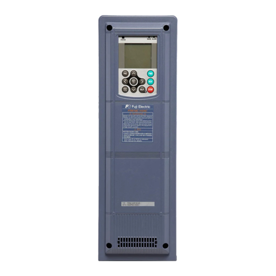
Fuji Electric FRENIC-HVAC Manual
Hide thumbs
Also See for FRENIC-HVAC:
- Instruction manual (39 pages) ,
- User manual (746 pages) ,
- Manual (140 pages)
Summary of Contents for Fuji Electric FRENIC-HVAC
- Page 1 High performance enabled by the comprehensive use of Fuji technology. Easy maintenance for the end-user.Maintains safety and protects the environment.Opens up possibilities for the new generation.
- Page 2 Smile to the Environment HVAC FRENIC- The first slim-type inverter specialized in energy-saving from Fuji Electric. Achieves a great effect on energy-saving of fans and pumps! Contributes drastically to cost reduction by cutting power consumption!
- Page 3 Large Contribution to Reducing Global Warming (Environmental Protection) with Energy Saving Wide variation in model capacity EMC filter built-in + DCR built-in type EMC filter built-in type Inverter capacity EMC filter DC reactor Protective structure Optimal control with energy-saving function Slim body Functions suitable for HVAC use Stand alone...
- Page 4 Significant Energy Saving Realized!!
- Page 6 Optimal Structure Design *Possible to show understandable indications through the unit conversion function. *Multi-language function: 19 languages + user customized language supported Alarm information for last ten times is stored and displayed with date and time. Possible to set the maximum four timers for a week. Possible to set ag holidays (20 days a year).
- Page 7 Multi-language supported, HELP function featured, unit Easy replacement just by simply removing and setting with SV and PV values, data copy (three kinds), detachable and can be attached on the panel (using an attaching the part. Life optional cable) prolongation is possible by controlling ON and OFF.
- Page 8 Functions Suitable for HVAC Use pressure to be controlled. 110 120 130 110 120 130...
- Page 9 temperature Set temperature Time fan high-speed operation Upper limiter unnecessary presumption control other materials using the output current and pressure sensor Time Step 1 Step 2 Step 2 Step 1 12 terminal X1 terminal output X2 terminal output terminal terminal regarded as improper.
- Page 10 φ > > φ > >...
- Page 11 Ω...
- Page 14 0.75 FRN0.75AR1 -4# FRN1.5AR1 -4# FRN2.2AR1 -4# 17.5 FRN3.7AR1 -4# FRN5.5AR1 -4# FRN7.5AR1 -4# 2x 8 FRN11AR1 -4# FRN15AR1 -4# 22.5 18.5 FRN18.5AR1 -4# FRN22AR1 -4# FRN30AR1 -4# 22.5 FRN37AR1 -4# FRN45AR1 -4# 184.5 99.5 2x 10 FRN55AR1 -4# 42.5 FRN75AR1 -4# 367.9 240.8...
- Page 17 (80) 17.5 68.5 2×M3 Panel cut part 2× 4 (5.8) 68.5 (17) 11.7 15.2 (53.8)
- Page 18 MCCB or Main circuit P(+) P(+) N(-) Power supply RCD/ELCB 200 V class series L1/R 200 to 240 V Motor 50/60Hz L2/S 400 V class series L3/T 380 to 480 V 50/60Hz - Power switching connector Auxiliary control power input (CN UX) - Fan power supply switching Auxiliary main circuit power input...
- Page 19 MCCB or Main circuit P(+) P(+) N(-) Power supply RCD/ELCB 200 V class series L1/R 200 to 240 V Motor 50/60Hz L2/S 400 V class series L3/T 380 to 480 V 50/60Hz - Power switching connector Auxiliary control power input (CN UX) - Fan power supply switching Auxiliary main circuit power input...
- Page 20 MCCB or Main circuit P(+) N(-) Power supply RCD/ELCB 200 V class series L1/R 200 to 240 V Motor 50/60Hz L2/S 400 V class series L3/T 380 to 480 V 50/60Hz - Power switching connector Auxiliary control power input (CN UX) - Fan power supply switching Auxiliary main circuit power input connector...
- Page 21 MCCB or Main circuit P(+) N(-) Power supply RCD/ELCB 200 V class series L1/R 200 to 240 V Motor 50/60Hz L2/S 400 V class series L3/T 380 to 480 V 50/60Hz - Power switching connector Auxiliary control power input (CN UX) - Fan power supply switching Auxiliary main circuit power input connector...
- Page 22 [EN1] and [PLC] and terminals [EN2] and [PLC]. (Do not put them together with any other control signal wire in the same shielded core.) that the inverter is no longer compliant with the EMC standards. To remove those screws, consult your Fuji Electric representative.
- Page 23 (OPC-ETH) Analog output: 1 analog voltage output point (0~±10V) 1 analog current output point (4~20mA) This is an interface card for connecting FRENIC-HVAC with peripherals (such as a master) via Ethernet. Analog current output interface card (OPC-AO) Pt100 temperature sensor input card (OPC-PT) This card allows two analog current output (4 to 20mA) points to be used.
- Page 24 NOTES • Measures against surge currents When running general-purpose motors Environmental conditions If an overvoltage trip occurs while the inverter is stopped or operated under a light load, it is • Driving a 400V general-purpose motor • Installation location assumed that the surge current is generated by When driving a 400V general-purpose motor with Use the inverter in a location with an ambient open/close of the phase-advancing capacitor in the...


Need help?
Do you have a question about the FRENIC-HVAC and is the answer not in the manual?
Questions and answers