Advertisement
Quick Links
Instruction Manual
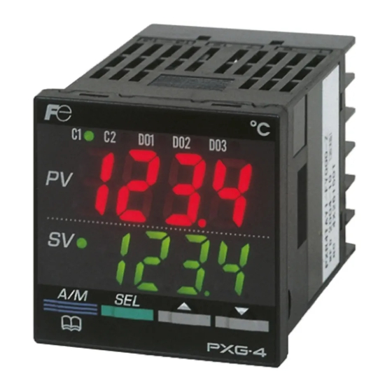
Model: PXG4
Fuji Electric Systems Co., Ltd.
Head Office
Gate City Osaki East Tower 11-2, Osaki 1-chome, Shinagawa-ku,
Tokyo 141-0032, Japan
http://www.fesys.co.jp/eng
Instrumentation Div./International Sales Dept.
NO.1, Fuji-machi, Hino-city, Tokyo 191-8502, Japan
Phone: 81-42-585-6201, 6202 Fax:81-42-585-6187
http://www.fic-net.jp/eng
Thank you for purchasing the Fuji Digital temperature Controller.
Once you have confirmed that this is the product you ordered, please use it in accordance with the following instructions.
For detailed information on operating this equipment, please refer to the separate operations manual.
In addition, please keep this instruction manual within easy reach of the actual person using this equipment.
The contents of this manual are subject to change without notice.
This manual is complied with possible care for the purpose of accuracy, however, Fuji Electric
Systems shall not be held liable for any damages, including indirect damage,
caused by typographical errors, absence of information or use of information in this manual.
Confirming Specifications and Accessories
Before using the product, confirm that it matches
the type ordered.
(For model code, please refer to page 19.)
Confirm that all of the following accessories are
included.
Temperature Controller
Instruction Manual
Mounting bracket
I/V Unit (250Ω Resistor)
Waterproof packing
Unit nameplate
Option
Name
Order No.
Terminal cover
ZZPPXR1-A230
PC loader
ZZPPXH1
*
TK4H4563
communication cable
Please Read First (Safety Warnings)
Please read this section thoroughly before using and observe the mentioned safety warnings
fully. Safety warnings are categorized as "Warning" or "Caution".
Warning
Mishandling may lead to death or serious injury.
Caution
Mishandling may cause injury to the user or property damage.
1
Warning
1-1
Limitations in Use
This product was developed, designed and manufactured on the premise that it would be used
for general machinery.
In particular, if this product is to be used for applications that require the utmost safety as
described below, please take into consideration of the safety of the entire system and the
machine by adopting such means as a fail-safe design, a redundancy design as well as the
conducting of periodical inspections.
•
Safety devices for the purpose of protecting the human body
Direct control of transportation equipment
•
•
Airplanes
Space equipment
•
•
Atomic equipment, etc
Please do not use this product for applications which directly involve human lives.
Micro Controller X
INP-TN1PXG4b-E
CAUTION
Related Information
Refer to the following reference materials for
details about the items described in this manual.
Document
Catalog
Micro Controller (Model: PXG)
1 unit
Operation Manual
1 copy
Micro Controller (Model: PXG)
Communication Functions
1 pc
Manual (MODBUS)
1 pc
The latest materials can also be downloaded at
the following URL: http://www.fic-net.jp/eng
1 pc
1 pc
1-2
●
This equipment is intended to be used under the following conditions.
Ambient temperature
Ambient humidity
Installation category
Pollution level
●
Between the temperature sensor and the location where the voltage reaches or generates
the values described below, secure clearance space and creepage distance as shown in
the table below.
If such space cannot be secured, the EN61010 safety compliance may become invalid.
Voltage used or generated
by any assemblies
Up to 50 Vrms or Vdc
Up to 100 Vrms or Vdc
Up to 150 Vrms or Vdc
Up to 300 Vrms or Vdc
Above 300 Vrms or Vdc
●
For the above, if voltage exceeds 50Vdc (called danger voltage), grounding and basic insulation
for all terminals of the equipment, and auxiliary insulation for digital outputs 1 to 3 is required,
Note that the insulation class for this equipment is as follows. Before installing, Please confirm
that the insulation class for equipment meets usage requirements.
Basic insulation (1500VAC)
Functional insulation (500VAC)
No insulation
Control output 1 (Relay contact)
Motorized valve OPEN output
Control output 2 (Relay contact)
Reference No.
Motorized valve CLOSE output
ECNO:1125
Digital output 1 (Relay contact)
ECNO:1411
Digital output 2 (Relay contact)
When the ninth digit in the
INP-
model code is J
TN514450-E
(Do1,2 are independent common) (Do1 to 3 shared common)
•
In cases where damage or problems with this equipment may lead to serious accidents,
install appropriate external protective circuits.
•
As this equipment does not have a power switch or fuses, install them separately as nec-
essary. Fuse should be wired between main power switch and this equipment. (Main
power switch: Bipolar breaker, fuse rating: 250V 1A)
For power supply wiring, use wire equal to 600V vinyl insulated wire or above.
•
•
To prevent damage and failure of the equipment, provide the rated power voltage.
To prevent shock and equipment failure, do not turn the power ON until all wiring is complete.
•
•
Before turning on power, confirm that clearance space has been secured to prevent shock
or fire.
•
Do not touch the terminal while the machine is on. Doing so risks shock or equipment errors.
Never disassemble, convert, modify or repair this equipment. Doing so risks abnormal
•
operation, shock or fire.
1-3
When installing or removing the equipment, turn the power OFF. Otherwise, shock, oper-
•
ational errors or failures may be caused.
Periodic maintenance is recommended for continuous and safe use of this equipment.
•
Some parts installed on this equipment have a limited life and/or may deteriorate with age.
•
The warranty period for this unit (including accessories) is one year, if the product is used
•
properly.
2
2-1
Please avoid installing in the following locations.
Locations in which the ambient temperature falls outside the range of –10 to 50°C when
•
equipment is in use. (If the power supply is 200V AC, the recommended maximum ambient
temperature is 45°C.)
•
Locations in which the ambient humidity falls outside the range of 45 to 90% RH when
equipment is in use.
•
Locations with rapid temperature changes, leading to dew condensation
Locations with corrosive gases (especially sulfide gas, ammonia, etc.) or flammable gases.
•
•
Locations with vibration or shock directly.
Locations in contact with water, oil, chemicals, steam or hot water.
•
(If the equipment gets wet, there is a risk of electric shock or fire, so have it inspected by
Fuji distributor.)
•
Locations with high concentrations of atmospheric dust, salt or iron particles.
Locations with large inductive interference, resulting in static electricity, magnetic fields or noise
•
•
Locations in direct sunlight.
Locations that build up heat from radiant heat sources, etc.
•
– 1 –
Installation and Wiring
-10 °C to 50 °C
90% RH or below (with no condensation)
II
2
Clearance Space (mm)
0.2
0.2
0.5
1.5
Please consult our distributor
Power
or
Control output 1 (SSR drive, current, voltage)
or
Control output 2 (SSR drive, current, voltage)
or Auxiliary analog output (Re-transmission output)
Digital output 1 to 3
(Relay contact)
When the ninth digit in the
model code is not J
Maintenance
Caution
Cautions when Installing
by IEC 1010-1
Creepage Space (mm)
1.2
hazardous
1.4
voltage
1.6
3.0
Internal circuit
Measurement input
Auxiliary analog input (remote SV)
Heater current detector input
Digital input 1 to 3
Communication (RS-485)
Advertisement

Related Manuals for Fuji Electric Micro Controller X PXG4


Summary of Contents for Fuji Electric Micro Controller X PXG4
- Page 1 The contents of this manual are subject to change without notice. This manual is complied with possible care for the purpose of accuracy, however, Fuji Electric Basic insulation (1500VAC) Systems shall not be held liable for any damages, including indirect damage, Functional insulation (500VAC) caused by typographical errors, absence of information or use of information in this manual.
- Page 2 • (Example) ment, etc. as relay output equipment are connected, use of “Z-trap,” manufactured by Fuji Electric Device Technology Co., Ltd., is recommended in order to protect the contacts against opening/closing surges and to ensure long-term use. Model names :...
- Page 3 Installation and Mounting External/Panel Cut Dimensions 79.8 Panel Panel thickness 1 to 8 mm 7-12 13-18 44.8 Terminal screw M3 Packing PC loader interface Mounting bracket installing multiple controllers Installing multiple controllers horizontally (In this installing, the waterproof of PXG is lost.) +0.5 +0.5 (48 ×...
- Page 4 Wiring Terminal Connection Diagram (100 to 240V AC, 24V AC/DC) ● Standard Type Communication function included RS485 RS485 communicator communicator – – Digital input RSV1 input CT input Digital input – DI-COM DI-COM RSV1 input – No communication function Digital input Digital input Digital input Digital input...
- Page 5 Display and Operations Parameter Parameter name Function Setting range Remarks display symbol F F F F A A A A L L L L T T T T " " (FALT) Error source Displays the display source of an error Part names and functions fixed at 0 8bit : PV input underflow...
- Page 6 Setting Parameters Parameter List The following explains how to set the parameters. Press and hold the key in operation mode, or manual mode. The following explains each channel parameter. This switches you to the monitor mode Mv1. The list also shows the operational range of set values for parameters that are limited. •...
- Page 7 Parameter Initial Parameter Initial Parameter name Function Setting range Remarks Parameter name Function Setting range Remarks display symbol value display symbol value. d d d d b b b b d d d d b b b b 7 7 7 7 "...
- Page 8 Parameter Initial Monitor (Ch5) Parameter name Function Setting range Remarks display symbol value [ [ [ [ 1 1 1 1 r r r r " " (C1r) OUT1 range Sets the range 0-5 (0 to 5V) 0-10 (Note9) You can check the ramp soak progress, control output, heater current, remaining time, and of the control 1-5 (1 to 5V) (voltage)
- Page 9 Parameter Parameter Initial Parameter Parameter Initial Function Setting range Remarks Function Setting range Remarks display symbol name value display symbol name value d d d d i i i i 1 1 1 1 S S S S t t t t m m m m d d d d "...
- Page 10 Display (Ch12) ON/OFF (2-position) Control 6-12 P P P P P P P P i i i i d d d d C C C C h h h h 2 2 2 2 Sets the parameter mask function Optional parameters can be set not to display. Acts as an ON/OFF control when the PID parameter is set to "...
-
Page 11: Output
● ● Normal type Low PV type Conditions where self-tuning cannot be used process value AT start process value AT start AT calculating AT calculating Self-tuning cannot be used in the following situations: SV-10%FS During control standby • During ON/OFF (2-position) control •... -
Page 12: Output
Manual Output Running ramp soak The following steps explain how to run ramp soak. Allows the control output to be manually set at an arbitrary value. ● Manual Mode Display Display the operation menu (" o o o o P P P P e e e e [ [ [ [ h h h h 1 1 1 1 "). - Page 13 Judgement Delay start Function Name Behavior play condition "2 2 2 2 1 1 1 1 " Start timer (DO1) Starts the specified timer for DO1. Ramp soak can be automatically started (RUN) after a certain period of time has elapsed Timer Timer "2 2 2 2 2 2 2 2 "...
- Page 14 Use the following steps to set DO. Digital Output 7-11 Display the system menu (" S S S S Y Y Y Y S S S S C C C C h h h h 7 7 7 7 "). Each of DO1 to DO3 can be assigned the following functions (events).
-
Page 15: Note
Communication Functions 7-12 Switching to remote SV operation o o o o P P P P E E E E [ [ [ [ h h h h 1 1 1 1 Set the following to communicate with the host. Display the operation menu ("... - Page 16 2. Error output function 5. SV selection function When the error output specification function has concluded that the equipment has an error, it The SV selection function can record and switch up to eight sets of SV information to the pal- halts the temperature controls and maintains the control output at a previously specified value.
- Page 17 ● Switch Using the User Key 10. MV limit function Display the palette menu (" P P P P L L L L T T T T C C C C h h h h 3 3 3 3 "). The MV limit function allows you to choose whether to limit the MV or let it pass through maxi- mum and minimum MV.
-
Page 18: Note
Error Indications Alarm Action Type Codes Type DO1 to DO3 Alarm Type Action diagram Display During Equipment Error No alarm – Absolute value High alarm This controller has a display function to indicate several types of error code shown below. If any alarm of the error code is displayed, please eliminate the cause of error immediately. -
Page 19: Relay
Type DO1 to DO3 Alarm Type Action diagram Model Specifications Zone alarm High/Low absolute alarm ALnh ALnL 12-1 PXG4 Standard Model List High/Low deviation alarm ALnh ALnL Digit Specifications 1 2 3 4 5 6 7 8 - 9 10 11 12 13 - 14 Notes High absolute/Low <Size of front WxH>... -
Page 20: Digital Output 2 8
PXG4 Motorized Valve Control Model List 12-2 Specifications Digit Specifications 1 2 3 4 5 6 7 8 - 9 10 11 12 13 - 14 Notes <Outer dimensions WxH> Power Supply 100 (-15%) to 240V AC (+10%), 50/60dHz, 24V DC/AC (±10%) 48 x 48 mm P X G 4 Power Consumption...
Need help?
Do you have a question about the Micro Controller X PXG4 and is the answer not in the manual?
Questions and answers