Advertisement
Quick Links
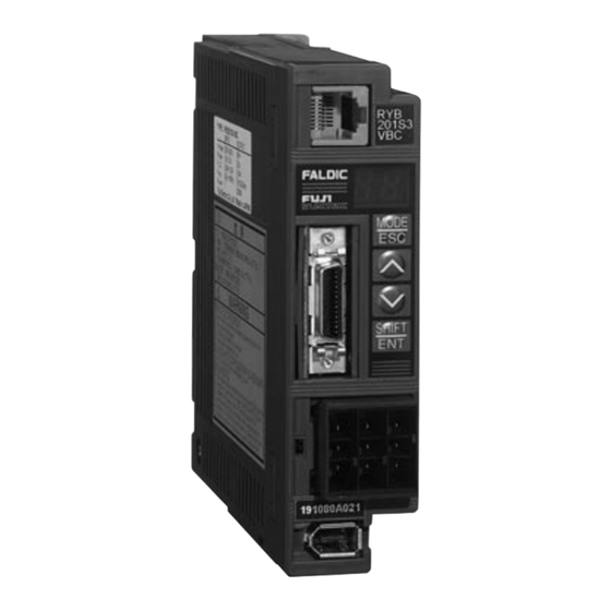
Fuji Electric RYB401S3-VBC-Z3
Servo Amplifer
A l l t r a d e m a r k s , b r a n d n a m e s , a n d b r a n d s a p p e a r i n g h e r e i n a r e t h e p r o p e r t y o f t h e i r r e s p e c t i v e o w n e r s .
• C r i t i c a l a n d e x p e d i t e d s e r v i c e s
• I n s t o c k / R e a d y - t o - s h i p
Artisan Scientific Corporation dba Artisan Technology Group is not an affiliate, representative, or authorized distributor for any manufacturer listed herein.
$
1450
.00
In Stock
Qty Available: 1
Used and in Excellent Condition
Open Web Page
https://www.artisantg.com/47701-1
• We b u y y o u r e x c e s s , u n d e r u t i l i z e d , a n d i d l e e q u i p me n t
• F u l l - s e r v i c e , i n d e p e n d e n t r e p a i r c e n t e r
Advertisement

Related Manuals for Fuji Electric FALDIC-b Series


Summary of Contents for Fuji Electric FALDIC-b Series
- Page 1 Fuji Electric RYB401S3-VBC-Z3 Servo Amplifer 1450 In Stock Qty Available: 1 Used and in Excellent Condition Open Web Page https://www.artisantg.com/47701-1 A l l t r a d e m a r k s , b r a n d n a m e s , a n d b r a n d s a p p e a r i n g h e r e i n a r e t h e p r o p e r t y o f t h e i r r e s p e c t i v e o w n e r s .
- Page 2 FUJI AC SERVO SYSTEM USER’S MANUAL MEH395 Downloaded from www.Manualslib.com manuals search engine...
- Page 3 Downloaded from www.Manualslib.com manuals search engine...
- Page 4 SAFETY INSTRUCTIONS In all stages of the installation, operation, maintenance and check of this equipment, reference must be made to this manual and other related documents. The correct understanding of the equipment, information about safety and other related instructions are essential for this system. Cautionary indications DANGER and CAUTION are used in this manual to point out particular hazards and to highlight some unusual information which must be specially noted.
- Page 5 Warning label The warning label in Fig. B is located at the arrow in Fig. A. Fig. A Warning display Fig. B Fig. B shows the following contents: n There is a risk of electric shock. Do not touch the amplifier when a commercial power is applied and for at least five minutes after de-energization.
- Page 6 DANGER Prior to inspection, turn off power and wait for at least five minutes. Otherwise, there is a risk of electric shock. Do not touch the amplifier when the commercial power is supplied. Otherwise, there is a risk of electric shock. CAUTION Do not disassemble the motor.
- Page 7 Descriptions given in this manual may be different from those of the product as a result of improvements of the product. Descriptions in this manual are subject to change without notice. Values are indicated in SI units (third stage) in this manual. The units may be different from those indicated on the product (nameplate).
- Page 8 Introduction This manual is the User’s Manual for Fuji’s FALDIC-β Series AC Servo System. The User’s Manual comes in one volume and covers all handling procedures of the product. The following document is included in the package of each device. Device Name of document Document No.
- Page 9 CONTENTS 1 OUTLINE 5 PARAMETERS 1-1) Outline ・・・・・・・・・・・・・・・・・・・・・・・・ 1- 2 5-1) Parameter configuration ・・・・・・・・・・・5- 2 1-2) Items to be confirmed ・・・・・・・・・・・ 1- 6 5-2) List of parameters ・・・・・・・・・・・・・・・・5- 4 1-3) Servomotor ・・・・・・・・・・・・・・・・・・・・ 1- 7 5-3) Basic settings ・・・・・・・・・・・・・・・・・・・・5- 6 1-4) Servo amplifier ・・・・・・・・・・・・・・・・・ 1- 8 5-4) System settings ・・・・・・・・・・・・・・・・・...
- Page 10 8 KEYPAD PANEL 11 SPECIFICATIONS 8-1) Display ・・・・・・・・・・・・・・・・・・・・・・・ 8- 2 11-1) List of servomotor 8-2) Function list ・・・・・・・・・・・・・・・・・・・ 8- 4 specifications ・・・・・・・・・・・・・・・・ 11- 2 8-3) State display mode・・・・・・・・・・・・・ 8- 5 11-2) List of servo amplifier 8-4) Monitor mode ・・・・・・・・・・・・・・・・・ 8- 8 specifications ・・・・・・・・・・・・・・・・...
- Page 11 Downloaded from www.Manualslib.com manuals search engine...
- Page 12 OUTLINE 1-1) Outline 1-2) Items to be confirmed 1-3) Servomotor 1-4) Servo amplifier 1-5) Type designation Downloaded from www.Manualslib.com manuals search engine...
- Page 13 Outline 1-1) Outline Requirements for functions and performance are sophisticated Fuji’s original vibration control function and notch filter are adopted for substantial suppression of mechanical vibration and a positioning setting time shorter than 1 ms is achieved in FALDIC-β Series in the pursuit of high performance and high precision.
- Page 14 Outline Advanced functions and performance of Fuji’s AC servo system n 50 to 750 W (rated speed: 3000 r/min) n 50 W to 5 kW (rated speed: 3000 r/min) n Slim or cubic motor n Slim or cubic motor n 16-bit incremental encoder n 16-bit absolute/incremental encoder n Exclusively used for pulse string input n Pulse string/analog input, DI/DO, SX bus,...
- Page 15 Outline Feature. 1 Suppresses mechanical vibrations to the maximum extent. “Damping Control Function” n n n n Equipped with a which is an effective countermeasure for vibration of the tips of robot arms, etc. Fuji’s original damping control function (Patent pending) In high tact operation of mechanisms with low rigidity, such as the tips of robot arms, suppression of arm tip vibration is a major factor in shortening tact time.
- Page 16 Outline Feature. 3 Servo amplifiers which are the Feature. 3 smallest in the industry, and can be installed side by side without 200V type, 200W actual size clearance. n n n n Innovative compact body 200V type, 200W: 35 (W) x 130 (H) x 130 (D) n n n n Side by side installation supports miniaturization of the control panel.
- Page 17 Outline 1-2) Items to be confirmed When the product (FALDIC-β Series) is delivered to you, unpack and check the following. Items to be confirmed Checking method Check mark Is the delivered FALDIC-β Check the “type” field in the motor and amplifier Series what you have nameplates shown in the following pages.
- Page 18 Outline 1-3) Servomotor n Appearance of product Frame Encoder The frame supports the A 16-bit serial encoder is output shaft of the housed on the side of the servomotor. The frame is servomotor opposite to the molded of resin. load. Output shaft The output shaft of the servomotor rotates.
- Page 19 1∅ / 3∅ 3∅ F.L.C 2.5A / 1.2A 1.5A Max. current → Freq. 50 or 60Hz 0 to 333.3Hz Frequency → Power 200W Capacity → Fuji Electric Co.,Ltd. Made in JAPAN Rated output Rated input Downloaded from www.Manualslib.com manuals search engine...
- Page 20 Outline 1-5) Type designation <Servo amplifier> [Basic type designation] RYB: Standard type [Voltage] No indication : 3-phase 200V [Capacity] : Single-phase 100V 201 : 20 201 : 20 X 10 1 1 1 1 = 200W 201 : 20 201 : 20 500 : 50 500 : 50 X 10 0...
- Page 21 Outline - MEMO - 1-10 Downloaded from www.Manualslib.com manuals search engine...
- Page 22 INSTALLATION 2-1) Servomotor 2-2) Servo amplifier Downloaded from www.Manualslib.com manuals search engine...
- Page 23 INSTALLATION 2-1) Servomotor (1) Storage temperature Store the servomotor in the following environment when leaving it without energization. : -20 to 60 °C Storage temperature Storage humidity : 10 to 90% RH (no condensation allowed) (2) Operating environment Operate the servomotor in the following environment. : -10 to 40 °C Operating temperature Operating humidity...
- Page 24 INSTALLATION (4) Handling The servomotor is equipped with a built-in encoder. Do not hammer the output shaft of the servomotor because the encoder is a precision device. Do not support the encoder to lift the servomotor during installation. The encoder built in the servomotor has been aligned with the servomotor. If it is disassembled, the rated performance will not be obtained.
- Page 25 INSTALLATION (6) Cable stress Do not apply bending or tensile stress to the cable. n Precautions for applications with moving servomotor - Design a system of an application with a moving servomotor so that the cables are free from forcible stress. - Route the encoder cable and power cable in Cableveyor.
- Page 26 INSTALLATION (9) Load The radial load and thrust load exerted on the shaft end of the servomotor are as follows. Radial load: Load exerted at right angles to motor shaft Thrust load: Load exerted in parallel to motor shaft n Servomotor Allowable radial load Allowable thrust load Type of servomotor...
- Page 27 INSTALLATION n Assembling the GYN gear head Follow the procedure below to assemble the GYN gear head. The procedure is similar for the GRN gear head. (1) Applying grease Before assembling the GYC/GYS motor to the gear head, apply grease on the output shaft of the servomotor.
- Page 28 INSTALLATION (3) Assembling the motor While aligning the input shaft of the gear head with the key, insert the output shaft of the servomotor. Tighten the screws of the gear head to fix the flange face of the motor to the flange face of the gear input shaft.
- Page 29 INSTALLATION 2-2) Servo amplifier (1) Storage temperature Store the servo amplifier in the following environment when leaving it without energization. : -20 to 85 °C Storage temperature Storage humidity : 10 to 90% RH (no condensation allowed) (2) Operating environment Operate the servomotor in the following environment.
- Page 30 INSTALLATION 2) The servo amplifier has the part that generates heat during operation. To mount multiple servo amplifiers in the same panel, observe the following precautions. - Mount side by side in principle. The RYB servo amplifier can be mounted closely. Use the amplifiers at 80% ED rating* if they are installed in contact with each other.
- Page 31 INSTALLATION (4) Handling The servo amplifier consists of electronic parts including microprocessors. Do not operate in the following environment. - Location near oil, steam or corrosive gas - Location with much dust Mount the servo amplifier in an airtight panel equipped with a forced ventilation fan when using it at places with much dust.
- Page 32 INSTALLATION (6) Depth of amplifier Allow 70 mm or more distance for a servo amplifier connected with a sequence input/output cable. Servo amplifier Sequence input/output cable Wall Power cable 130 (Common among all types) 2-11 Downloaded from www.Manualslib.com manuals search engine...
- Page 33 INSTALLATION -MEMO- 2-12 Downloaded from www.Manualslib.com manuals search engine...
- Page 34 WIRING 3-1) Construction 3-2) Servo amplifier 3-3) Servomotor 3-4) Encoder 3-5) Standard connection diagrams 3-6) Connection examples Downloaded from www.Manualslib.com manuals search engine...
- Page 35 WIRING 3-1) Configuration The configuration of FALDIC-β Series is as follows. (1) Servomotor (without brake) FAB/ELB FAB or ELB is installed in the primary circuit of the servo amplifier to avoid losses caused by shutdown or power-on or short- FAB/ELB circuit current.
- Page 36 WIRING General-purpose PC PC Loader for FALDIC-β is (2) Servomotor (with brake) prepared (option). FAB/ELB Controller Various controllers of the pulse string output type can be used. AC reactor SCPU32 SCPU32 SCPU32 SCPU32 ONL 0 1 2 3 4 5 6 7 ONL 0 1 2 3 4 5 6 7 ONL 0 1 2 3 4 5 6 7 ONL 0 1 2 3 4 5 6 7...
- Page 37 WIRING 3-2) Servo amplifier Supply commercial power shown in Chapter 11 to the amplifier. Do not supply commercial power to the servomotor. If attempted, the motor will be broken. (1) Commercial power supply n 3-phase 200V series Supply 200V commercial power to the servo amplifier. Connect the power cables to the L1, L2 and L3 terminals.
- Page 38 WIRING (2) Power supply capacity The power supply capacity required for each servo amplifier is as follows. The same power supply capacity applies to the step-up or step-down transformer. The specified power supply capacity is for the designated cable size and a wiring length of 20m. If the power supply capacity is 500 kVA or more, an AC reactor specified in section 10-6 should be provided.
- Page 39 WIRING (3) Main circuit terminals The power cable for the servo amplifier, external regenerative resistor (option) and servomotor power cable are connected at the main circuit terminals. The main circuit terminals accept connectors. The connector is not included in the accessories of the servo amplifier.
- Page 40 WIRING (4) Sequence input/output terminal Connect the signal cable of a host controller to connector 1 (CN1) of the servo amplifier. 26 M5 *FFB *FFZ *FFA CONT5 CONT4 PSET CONT3 Compatible connector on cable side CONT2 CONT1 OUT1 Soldered plug: 10126-3000V Shell kit : 10326-52A0-008 n List of sequence functions...
- Page 41 WIRING n Interface circuit diagram Signal name Specification Circuit DC24V 2.2k 24VDC, 10mA Sequence input (For each point) Servo amplifier +30VDC, 50mA Sequence output (Max.) DC24V Servo amplifier 1.5k CA(CB) Pulse string input Differential input (Differential output) *CA(*CB) Servo amplifier 1.5k CA(CB) Pulse string input...
- Page 42 WIRING * The pulse train input can be a 12 VDC input. In this case, the wiring method varies. Refer to the drawing in item (3) below. n Examples of recommended wiring for command pulse (1) Differential output devices Shielding wire Line driver IC;...
- Page 43 WIRING 3-3) Servomotor (1) Servomotor Connect the power cable of the servomotor to the U, V and W terminals of the servo amplifier while identifying the symbols. Do not supply commercial power directly to the servomotor. If attempted, the magnet inside the motor will be de-magnetized and the servomotor will not rotate.
- Page 44 WIRING n Connector for GYC/GYS type Motor power cable on motor side Without brake (Viewed from contact inserting side) 1 cap housing Projection 350780-1 type (Japan AMP) 4 contactors (socket) 350750-3 or 350689-3 type (Japan AMP) U V W Motor power cable on motor side (Viewed from contact inserting side) Projection...
- Page 45 WIRING 3-4) Encoder The servomotor is equipped with a 16-bit serial encoder (exclusively for incremental mode). Connect the encoder wiring to CN2 of the servo amplifier. The wiring connector is not included in accessories. An optional cable with connectors at both ends is prepared. The maximum wiring length of the encoder is 50 m with limitations from the cable size.
- Page 46 WIRING - Wiring cable Use the following cables if the optional encoder cable is not used. n Cross-link polyethylene insulated, vinyl sheath cable for robot travel (DAIDEN Co., Ltd.) RMCV-SB (UL2464) AWG# 25/2P + AWG# 23/2C (twisted-pair cable) (Cable length: within 10m) Twisted 2P (pairs), 2C (core) composite cable of different cable sizes Note: Use the core with larger sectional area for power supply.
- Page 47 WIRING -MEMO- 3-14 Downloaded from www.Manualslib.com manuals search engine...
- Page 48 WIRING 3-5) Standard connection diagrams Connection diagrams of the servo amplifier are shown here. n 3-phase 200V (without brake) n 3-phase 200V (with brake) n Single-phase 100V (without brake) n Single-phase 100V (with brake) 3-15 Downloaded from www.Manualslib.com manuals search engine...
- Page 49 WIRING n Three-phase 200 V (without brake) External regenerative resistor (option) Commercial power supply M 3-phase 200V 1 P5 2 M5 PG SIG+ 5 5 SIG+ SIG- 6 19 PPI 6 SIG- Power input for pulse string open-collector input 7 CA Pulse train input 8 *CA (differential) Servomotor 20 CB (Without brake) 21 *CB...
- Page 50 WIRING n Three-phase 200 V (with brake) External regenerative resistor (option) Commercial power supply M 3-phase 200V 5 Br Power supply 6 Br for brake 24 VDC 1 P5 2 M5 PG SIG+ 5 5 SIG+ SIG- 6 Power input for pulse string open-collector input 6 SIG- 19 PPI 7 CA...
- Page 51 WIRING n Single-phase 100 V (without brake) External regenerative resistor (option) Commercial power supply M Single-phase 100 V 1 P5 2 M5 PG SIG+ 5 5 SIG+ SIG- 6 6 SIG- 19 PPI Power input for pulse string open-collector input 7 CA 8 *CA Pulse train input Servomotor 20 CB (differential) (Without brake)
- Page 52 WIRING n Single-phase 100 V (with brake) External regenerative resistor (option) Commercial power supply M Single-phase 100V 5 Br Power supply 6 Br for brake 24 VDC 1 P5 2 M5 PG SIG+ 5 5 SIG+ SIG- 6 19 PPI 6 SIG- Power input for pulse string open-collector input 7 CA 8 *CA Pulse train input...
- Page 53 WIRING -MEMO- 3-20 Downloaded from www.Manualslib.com manuals search engine...
- Page 54 WIRING 3-6) Connection examples Connection diagrams for combination examples of the servo amplifier with relevant devices are shown. For products not specified in this manual, be sure to refer to the operation manual or user’s manual of the corresponding equipment. The connection diagrams shown in this chapter are for reference only. n Programmable controller (NWOP40o-o) n Positioning module (NP1F-MP2) n Positioning module (NC1F-VP1)
- Page 55 WIRING Controller side n Programmable controller (NWOP40o-o) For one-axis control of SPB (programmable controller) through pulse string outputs Axis control can be made with the basic unit. The form of the output pulse is command pulse and command sign. For the programmable logic controller, refer to the operation manual or user’s manual. ⑤...
- Page 56 WIRING Servo side n Programmable controller (NWOP40o-o) External regenerative resistor (Option) Commercial power M supply 3-phase 200 V 1 P5 2 M5 PG SIG+ 5 5 SIG+ SIG- 6 19 PPI 6 SIG- ① 7 CA ② 8 *CA ③ 20 CB ④ 21 *CB Servomotor (Without brake) ⑤ *FFA 10 1 P24 *FFB 12 2 CONT1...
- Page 57 WIRING Controller side n Positioning module (NP1F-MP2) Example of connection with MICREX-SX series pulse-string output two-axis positioning module. The control type is semi-closed loop with 500kHz maximum input frequency. For the programmable logic controller, refer to the operation manual or user’s manual. Manual pulse generator, phase A Manual pulse generator, phase Manual pulse generator, phase B...
- Page 58 WIRING Servo side n Positioning module (NP1F-MP2) External regenerative resistor (Option) Commercial power M supply 3-phase 200V 1 P5 2 M5 PG SIG+ 5 5 SIG+ SIG- 6 19 PPI 6 SIG- ① 7 CA ② 8 *CA ③ 20 CB Servomotor ④ (Without brake) 21 *CB ⑤ ⑪ *FFA 10 ⑥...
- Page 59 WIRING Controller side n Positioning module (NC1F-VP1) Example of connection with positioning module for MICREX-F series F70. Linear positioning can be executed. - The pulse string of NC1F-VP1 is open collector output. - The output form is forward rotation pulse and reverse rotation pulse in the factory setting. - The automatic start signal does not become valid if the MON output is left active.
- Page 60 WIRING Servo side n Positioning module (NC1F-VP1) External regenerative resistor (Option) Commercial power M supply 3-phase 200V 1 P5 2 M5 PG SIG+ 5 5 SIG+ SIG- 6 19 PPI 6 SIG- ① 7 CA ② 8 *CA ③ 20 CB Servomotor ④ 21 *CB (Without brake) ⑦ *FFA 10 1 P24 *FFB 12 2 CONT1...
- Page 61 WIRING Controller side n Positioning unit (AD75 type) Example of connection with AD75 type positioning unit made by Mitsubishi Electric Co., Ltd. Only connections between the AD75 positioning unit and servo amplifier are shown. For the programmable logic controller, refer to the operation manual or user’s manual of the equipment.
- Page 62 WIRING Servo side n Positioning unit (AD75 type) <Setting example> l AD75 positioning unit The pulse output mode is used to output CW/CCW pulses. External regenerative resistor (Option) Commercial power M supply 3-phase 200V 1 P5 2 M5 PG SIG+ 5 5 SIG+ SIG- 6 19 PPI 6 SIG- ①...
- Page 63 WIRING Controller side n Position control unit (C200HW-NC113 type) Example of connection with C200HW-NC113 position control unit made by Omron Corp. Only connections between the C200HW-NC113 position control unit and servo amplifier are shown. For the programmable logic controller, refer to the operation manual or user’s manual of the equipment.
- Page 64 WIRING Servo side n Position control unit (C200HW-NC113 type) <Setting example> l C200HW-NC113 position control unit The pulse output mode is used to output CW and CCW pulses. External regenerative resistor (Option) Commercial power M supply 3-phase 200V 1 P5 2 M5 PG...
- Page 65 WIRING -MEMO- 3-32 Downloaded from www.Manualslib.com manuals search engine...
- Page 66 TEST OPERATION 4-1) Test operation in two stages 4-2) First stage 4-3) Second stage Downloaded from www.Manualslib.com manuals search engine...
- Page 67 TEST OPERATION 4-1) Test operation in two stages Perform test operation in the following two stages. n First stage Check wiring and product or parameters. Use only the servomotor and servo amplifier without connection of the servomotor to the machine, and perform test operation.
- Page 68 TEST OPERATION 4-2) First stage Connect the servo amplifier and servomotor to perform test operation. Refer to Chapter 3 for the wiring method. Do not connect the servomotor to the mechanical system when performing test operation. Check the following items in the first stage. <Items to be checked>...
- Page 69 TEST OPERATION (4) Perform test operation at the keypad panel. Use the keypad panel to turn the servomotor. Check that the servomotor turns in the correct direction. Basic setting parameter #04 Initial Name Setting range Change value 0: Forward rotation (CCW) Direction of rotation switch Power 1: Reverse rotation (CW)
- Page 70 TEST OPERATION 4-3) Second stage Mount the servo amplifier to the host controller and mount the servomotor to the machine to perform test operation. The test operation should be conducted in the final operation state. Check the following items in the second stage. <Items to be checked>...
- Page 71 TEST OPERATION -MEMO- Downloaded from www.Manualslib.com manuals search engine...
- Page 72 PARAMETERS 5-1) Parameter configuration 5-2) List of parameters 5-3) Basic settings 5-4) System settings 5-5) Control system settings 5-6) For adjustment by manufacturer Downloaded from www.Manualslib.com manuals search engine...
- Page 73 PARAMETERS 5-1) Parameter configuration Various parameters are used to set up the mechanical system and adjust the characteristics and accuracy of servo. The parameters of FALDIC-β Series are divided into the four major groups (basic setting, system setting, control system setting and adjustment by manufacturer) shown in the table below. Parameter configuration Parameter Type...
- Page 74 PARAMETERS n Parameter editing method There are two parameter editing methods: through keypad panel operation and through PC loader operation. (1) Parameter editing through keypad panel operation MODE MODE MODE MODE Press the key to select the parameter editing mode and press the key to select the desired parameter number.
- Page 75 PARAMETERS 5-2) List of parameters n List of parameters of FALDIC-β (1) Name Setting range Initial value Change Page Basic settings Command pulse correction α 1 to 32767 (in 1 increments) Always Command pulse correction β 1 to 32767 (in 1 increments) Always 0: Command pulse/command sign, 1: Forward/reverse rotation pulse,...
- Page 76 PARAMETERS n List of parameters of FALDIC-β (2) Name Setting range Initial value Change Page Control system settings Position controller gain 1 1 to 1000 [rad/sec] (in 1 increments) Always Speed response 1 1 to 1000 [Hz] (in 1 increments) Always 5-46 Speed controller integration...
- Page 77 PARAMETERS 5-3) Basic settings The basic setting parameters are described in the order of the parameter number. Basic setting parameter #01 and #02 Name Setting range Initial value Change 1 to 32767 (in 1 increments) Always Command pulse correction α Command pulse correction β...
- Page 78 PARAMETERS To couple 10-mm-lead screw to the output shaft of the servomotor with a setting unit of 1/100 (Mechanical system travel distance per revolution α (Command pulse correction of servomotor) = (Unit quantity) × β (65536 pulses/rotation) (Command pulse correction α 10 mm (Command pulse correction ×...
- Page 79 PARAMETERS Basic setting parameter #03 Name Setting range Initial value Change 0: Command pulse / command sign, Pulse string input 1: Forward / reverse rotation pulse, Power form 2: Two signals with 90-degree phase difference The form of the signal added to the pulse string input terminal can be selected. The form of pulse strings added to the [CA], [*CA], [CB] and [*CB] pulse string input terminals of the servo amplifier can be specified.
- Page 80 PARAMETERS n Forward / reverse rotation pulse (Setting of basic setting parameter 03: 1) The forward rotation pulse indicates the rotation amount in the positive direction, while the reverse pulse indicates that in the reverse direction. - Differential input Forward rotation command Reverse rotation command t1 t1 t3 t3...
- Page 81 PARAMETERS Basic setting parameter #04 Name Setting range Initial value Change Direction of rotation 0: Positive direction: Forward rotation (CCW), Power switch 1: Positive direction: Reverse rotation (CW) Use this parameter to keep consistency between the direction of rotation of the servomotor and mechanical travel direction.
- Page 82 PARAMETERS Basic setting parameter #05 Name Setting range Initial value Change 0: Auto tuning, Tuning mode 1: Semi-auto tuning, Always 2: Manual tuning Select the tuning method of the servo amplifier. n Auto tuning (Setting of basic setting parameter 05: 0) This is the factory setting of the servo amplifier.
- Page 83 The calculation formula for obtaining the moment of inertia is described in appendix. * Capacity selection software can be used for automatic calculation. The capacity selection software can be downloaded free of charge from Fuji Electric’s home page. http://web1.fujielectric.co.jp/kiki-info/User/index.html 5-12 Downloaded from www.Manualslib.com...
- Page 84 PARAMETERS Basic setting parameter #07 Name Setting range Initial value Change Auto tuning gain 1 to 20 (in 1 increments) Always Specify the response of the servomotor used in the auto tuning or semi-auto tuning mode. Specify a larger value to reduce the command follow-up time and positioning setting time, but too large a value cause the motor to vibrate.
- Page 85 PARAMETERS Basic setting parameter #08 and #09 Name Setting range Initial value Change Not used These parameters are not used. 5-14 Downloaded from www.Manualslib.com manuals search engine...
- Page 86 PARAMETERS -MEMO- 5-15 Downloaded from www.Manualslib.com manuals search engine...
- Page 87 PARAMETERS 5-4) System settings System setting parameters are described in the order of the parameter number. System setting parameters #10 through #14 Name Setting range Initial value Change CONT 1 signal 0 to 10 (in 1 increments) 1 [RUN] Power allocation 0: Not specified 1: Operation command [RUN]...
- Page 88 PARAMETERS n Each sequence input/output signal can be monitored in the trace screen of the PC loader. The ready [RDY] and positioning end [PSET] signals among sequence output signals are fixed at the OUT terminals. O: Terminal allocation and waveform trace are possible. CONT Sequence input signal PC loader...
- Page 89 PARAMETERS (1) Operation command [RUN] This signal makes the servomotor ready to rotate. Sequence input signal Operation command [RUN].. Assigned to CONT 1 with factory setting n Function The servomotor is ready to rotate while the operation command [RUN] signal remains active. The servomotor does not rotate if motor power is supplied but the operation command signal is turned off.
- Page 90 PARAMETERS (2) Reset [RST] Alarm detection of the servo amplifier is reset. Sequence input signal Reset [RST] ... Assigned to CONT 2 with factory setting n Function The sequence input signal resets the alarm detected at the servo amplifier. Alarm detection is reset upon the activating edge of the reset [RST] signal. n Alarms that can be reset n Alarms that cannot be reset Indication...
- Page 91 PARAMETERS (3) Overtravel and overtravel detection Movement of the machine can be forcibly stopped upon a signal from a limit switch or the like. Sequence input/output signal Overtravel / overtravel detection n Function +OT (3)/-OT (4) These are input signals from limit switches for the prevention of overtravel (OT) at the end of the moving stroke of the machine.
- Page 92 PARAMETERS APS30 APS30 SCPU32 SCPU32 SCPU32 SCPU32 SCPU32 SCPU32 SCPU32 SCPU32 ONL 0 1 2 3 4 5 6 7 ONL 0 1 2 3 4 5 6 7 ONL 0 1 2 3 4 5 6 7 ONL 0 1 2 3 4 5 6 7 ONL 0 1 2 3 4 5 6 7 ONL 0 1 2 3 4 5 6 7 ONL 0 1 2 3 4 5 6 7...
- Page 93 PARAMETERS (4) Forced stop and forced stop detection This signal supplied at the sequence input terminal stops the servomotor forcibly. Sequence input/output signal Forced stop/forced stop detection n Function (1) Forced stop The servomotor is forcibly stopped (with a b-contact) while the forced stop (5) signal is turned off. This signal is valid in all control states and it is executed at the highest priority.
- Page 94 PARAMETERS (2) State of forced stop If forced stop (5) is inactive and operation command [RUN] is active, the servomotor is stopped with the zero speed command state. The zero speed state is valid in all control forms. Activate forced stop to ready the servomotor for operation. Deactivate the operation command [RUN] signal to coast to stop.
- Page 95 PARAMETERS (5) P-action Proportional band control is adopted as a control method of the servo amplifier. Sequence input signal P-action n Function Activate this signal while the operation command [RUN] signal is active with the motor shaft being mechanically locked. If P-action is activated during rotation of the servomotor, position control becomes unstable.
- Page 96 PARAMETERS (6) Deviation clearance Difference (deviation) between the command position and feedback position is reduced to zero. Sequence input signal Deviation clearance n Function While this signal remains active, the difference between the command position and feedback position is reduced to zero. The feedback position is made the command position. n Parameter setting To assign deviation clearance to a sequence input terminal, specify the corresponding value (“7”) to the system setting parameter.
- Page 97 PARAMETERS (7) External regenerative resistor overheat The electronic thermal relay signal of the optional external regenerative resistor is used to forcibly stop the servomotor. Sequence input signal External regenerative resistor overheat n Function The servomotor is forcibly stopped (with a b-contact) while the external regenerative resistor overheat signal is inactive.
- Page 98 PARAMETERS (8) Anti-resonance frequency selection 0/1 Set any of the four anti-resonance frequencies. Sequence input signal Anti-resonance frequency selection 0/1 n Function Select any of the four anti-resonance frequencies by setting two ON/OFF bits. Anti-resonance frequency Anti-resonance frequency Anti-resonance frequency selection 1 selection 0 Parameter #61*...
- Page 99 PARAMETERS (9) Alarm detection: a-contact (b-contact) The servo amplifier detects the action (alarm) of protection function to activate (desactivate)* the signal. Alarm detection: a-contact ... Assigned to OUT1 with shipment setting Sequence output signal Alarm detection: b-contact n Function The signal is activated (deactivated*) and is held at the servo amplifier when the servo amplifier detects an alarm.
- Page 100 PARAMETERS (10) Dynamic brake The signal is activated when the servo amplifier detects a major fault. Sequence output signal Dynamic brake n Function The signal is activated when the servo amplifier detects a major fault with which the servomotor cannot be driven, and it is retained until an alarm reset signal is input. When the dynamic brake is applied, three phases of the synchronous motor are short-circuited to generate power.
- Page 101 PARAMETERS (11) Ready [RDY] The signal is activated when the motor is ready to rotate. Sequence output signal Ready [RDY] n Function The signal is activated when the following conditions are satisfied: 1) Active operation command [RUN] (1) signal 2) Active forced stop [EMG] (5) signal* 3) Inactive alarm detection: a-contact (1) signal (Or active alarm detection: b-contact (2) signal) 4) Active external regenerative resistor overheat (8) signal* 5) Source voltage above 150V...
- Page 102 PARAMETERS (12) Positioning end [PSET] Use the signal to check that the positioning action has been completed. Sequence output signal Positioning end [PSET] n Function The signal is active when the following conditions are satisfied. 1) There is no alarm. 2) The rotation speed is within the zero speed width specified at parameter #21.
- Page 103 PARAMETERS System setting parameter #17 Name Setting range Initial value Change Output pulse count 16 to 16384 [pulse] (in 1 increments) 2048 Power Specify the number of pulses output per each revolution of the servomotor. The output form is two signals having 90-degree phase difference. A phase-B advance signal is output during forward rotation of the output shaft of the servomotor.
- Page 104 PARAMETERS System setting parameter #18 Name Setting range Initial value Change Phase-Z offset 0 to 65535[pulse] (in 1 increments) Power Specify the parameter to change the output position of the phase-Z signal. There is a counterclockwise delay in the output position of the phase-Z signal by the number of pulses specified in system setting parameter #18.
- Page 105 PARAMETERS System setting parameter #19 Name Setting range Initial value Change Zero deviation width 1 to 10000 [pulse] (in 1 increments) Always Specify the width of the zone where the zero deviation signal is activated* in the number of encoder pulses.
- Page 106 PARAMETERS System setting parameter #20 Name Setting range Initial value Change Deviation limit width 10 to 65535 [× 100 pulse] (in 1 increments) 10000 Always Specify the number of pulses for detecting the deviation limit (for alarm detection) in the number of encoder feedback pulses (not command pulses).
- Page 107 PARAMETERS System setting parameter #21 Name Setting range Initial value Change Zero speed width 10 to 5000 [r/min] (in 1 increments) Always Use the parameter to judge if the servomotor is stopped. Specify the width where the zero speed signal is activated*.
- Page 108 PARAMETERS System setting parameter #22 Name Setting range Initial value Change Positioning end 0.000 to 1.000 sec. (in 0.001 increments) 0.000 Always judgment time Specify the time for judgment of the end of positioning. If the zero deviation signal (system setting parameter #19) and zero speed signal (system setting parameter #21) remain active in the positioning end judgment time (system setting parameter #22), the positioning end signal is activated.
- Page 109 PARAMETERS System setting parameter #24 Name Setting range Initial value Change Undervoltage alarm detection 0: No detection, 1: Detection Power Specify whether or not alarm detection is made upon detection of undervoltage in the power supply under active operation command [RUN]. System setting parameter #24 Setting range Alarm...
- Page 110 PARAMETERS System setting parameter #25 Name Setting range Initial value Change Regenerative resistor 0: Invalid, electronic thermal 1: Valid (optional regenerative resistor Power calculation (thin type)) Specify the parameter when connecting the optional external regenerative resistor (thin type) (WSR- ooo-T). System setting parameter #25 Regenerative resistor Setting...
- Page 111 PARAMETERS System setting parameter #26 Name Setting range Initial value Change Dynamic brake on overtravel 0: Invalid, Power detection valid/invalid 1: Valid Specify the parameter for models equipped with the optional dynamic brake unit (will be sold later). 5-40 Downloaded from www.Manualslib.com manuals search engine...
- Page 112 PARAMETERS System setting parameter #27 Name Setting range Initial value Change Parameter write-protection 0: Write-enable, 1: Write-protected Always Parameter editing is prohibited. Even if write-protection is selected with system setting parameter #27, system setting parameter #27 can be edited. System setting parameter #28 Name Setting range Initial value...
- Page 113 PARAMETERS System setting parameters #29 and #30 Name Setting range Initial value Change Speed setting 1 to 5000 [r/min] (in 1 increments) Always (for test operation) Acceleration / deceleration time 0.000 to 9.999 sec. (in 0.001 increments) 0.100 Always (for test operation) Specify the test operation speed and acceleration and deceleration time.
- Page 114 PARAMETERS System setting parameters #31 through #39 Name Setting range Initial value Change Not used These parameters are not used. 5-43 Downloaded from www.Manualslib.com manuals search engine...
- Page 115 PARAMETERS 5-5) Control system settings Control system setting parameters are described in the order of the parameter number. n Control block diagram The control block diagram of FALDIC-β Series is shown. Command follow-up control selection Parameter #56 Command follow-up control Feed forward Parameter #44 Parameter #45*...
- Page 116 PARAMETERS Current PI control Notch filter control Parameters Parameter Parameters #57 Parameter #47 #41, #42* #46* through #60 Position detection Speed detection * Parameters shown in the shaded box are automatically adjusted. 5-45 Downloaded from www.Manualslib.com manuals search engine...
- Page 117 PARAMETERS Control system setting parameters #40 through #42 Name Setting range Initial value Change Position controller gain 1 1 to 1000 [rad/sec] (in 1 increments) Always Speed response 1 1 to 1000 [Hz] (in 1 increments) Always Speed controller 1.0 to 1000.0 [msec] (in 0.1 increments) 25.9 Always integration time 1...
- Page 118 PARAMETERS n Position controller gain 1 (Control system setting parameter 40) This parameter determines the response of the position control loop. A larger setting improves the response to the position command, while too large a setting is likely to generate overshoot. n Speed response 1 (Control system setting parameter 41) This parameter determines the response of the speed control loop.
- Page 119 PARAMETERS Control system setting parameter #43 Name Setting range Initial value Change S-curve time constant 0.0 to 100.0 [msec] (in 0.1 increments) Always The servomotor can be accelerated or decelerated moderately in the S-curve pattern. If the pulse string input is given at a constant frequency, the servomotor accelerates or decelerates at the time constant of the set time.
- Page 120 PARAMETERS Control system setting parameter #47 Name Setting range Initial value Change Speed setting filter 0.00 to 20.00 [msec] (in 0.01 increments) 0.00 Always Specify the parameter to filter the speed command. * No change is necessary in principle. 5-49 Downloaded from www.Manualslib.com manuals search engine...
- Page 121 PARAMETERS Control system setting parameters #48 through #53 Name Setting range Initial value Change 0: Position deviation (x 10), Gain switching factor 1: Feedback speed, Always 2: Command speed Gain switching level 1 to 1000 (in 1 increments) Always Gain switching time constant 0 to 100 [msec] (in 1 increments) Always Position controller gain 2...
- Page 122 PARAMETERS Control system setting parameters #54 and #55 Name Setting range Initial value Change Position gain added when 0 to 1000 [rad/sec] (in 1 increments) Always setting Addition limit when setting 0 to 200 [r/min] (in 1 increments) Always Increase the position gain at the time of stopping to reduce the setting time or to enhance the rigidity. Do not use in regular cases.
- Page 123 PARAMETERS Control system setting parameters #57 through #60 Name Setting range Initial value Change Notch filter 1 frequency 10 to 200 [x 100 Hz] (in 1 increments) Always Notch filter 1 damping amount 0 to 40 [dB] (in 1 increments) Always Notch filter 2 frequency 10 to 200 [x 10Hz] (in 1 increments)
- Page 124 PARAMETERS Control system setting parameters #61 through #64 Name Setting range Initial value Change Anti-resonance frequency 0 5.0 to 200.0 [Hz] (in 0.1 increments) 200.0 Always Anti-resonance frequency 1 5.0 to 200.0 [Hz] (in 0.1 increments) 200.0 Always Anti-resonance frequency 2 5.0 to 200.0 [Hz] (in 0.1 increments) 200.0 Always...
- Page 125 PARAMETERS 5-6) For adjustments by manufacturer These parameters are for adjustments by the manufacturer. Do not change them. Parameters #80 through #83 for adjustment by manufacturer Name Setting range Initial value Change For adjustment by Adjusted manufacturer 1 value For adjustment by Adjusted manufacturer 2 value...
- Page 126 ADJUSTMENT OF SERVO 6-1) Basic adjustment 6-2) Application adjustment 6-3) Adjustment requiring high speed response Downloaded from www.Manualslib.com manuals search engine...
- Page 127 ADJUSTMENT OF SERVO 6-1) Basic adjustment The servomotor must be tuned so that it reliably obeys commands sent from the host controller. The tuning method of FALDIC-β Series includes three types: auto tuning, semi-auto tuning and manual tuning (parameter #5). Be sure to operate the servomotor in the auto tuning mode (factory setting) for the first time when operating it.
- Page 128 ADJUSTMENT OF SERVO n Parameters automatically adjusted in the auto or semi-auto tuning mode Tuning mode Name 0: Auto 1: Semi-auto ¡ Load inertia ratio - (Updated every 10 minutes) ¡ ¡ Auto tuning gain Position controller - (Always updated) - (Fixed) gain Speed response...
- Page 129 ADJUSTMENT OF SERVO 6-2) Application adjustment Use this adjustment method when adjustment is not satisfactory after the procedure described in section 6-1 “Basic adjustment” or if the servomotor vibrates and the auto tuning gain (parameter #7) cannot be increased sufficiently. START * Decrease the speed response (parameter #52).
- Page 130 ADJUSTMENT OF SERVO 2. Adjust the large inertia. Note: The inertia ratio must be no larger than 100 times in principle. n How to check if the load inertia ratio exceeds 100 times i) Use capacity selection software to automatically calculate the load inertia. ii) Use monitor mode 09 (load inertia ratio) at the keypad panel to assume.
- Page 131 ADJUSTMENT OF SERVO n How to set the notch filter (parameters #57 through #60) i) Use the servo analysis function of the optional PC loader to locate the resonance point of the machine. Resonance point Gain 2 Depth [dB] 1 Resonance frequency Frequency [Hz] ii) Set the resonance frequency and damping amount at the resonance point of the machine in parameters.
- Page 132 ADJUSTMENT OF SERVO 6-3) Adjustment requiring high speed response Use this method to obtain quicker response than that obtained after adjustment specified in section 6-2 “Application adjustment.” (However, do not use the method described here if “adjustment of large inertia” has been made.) While measuring the operation time and output timing of the positioning end signal by using historical trace of the PC loader, make adjustment as follows.
- Page 133 ADJUSTMENT OF SERVO -MEMO- Downloaded from www.Manualslib.com manuals search engine...
- Page 134 SPECIAL ADJUSTMENT 7-1) Vibration control 7-2) Command follow-up control 7-3) Position gain and limit added when setting Downloaded from www.Manualslib.com manuals search engine...
- Page 135 SPECIAL ADJUSTMENT 7-1) Vibration control 7-1-1) What is dumping control? (1) Purpose of dumping control In a structure such as the robot arm and transfer machine where the structure has a spring characteristic, vibration occurs at the end of the workpiece during abrupt acceleration or deceleration of the motor.
- Page 136 SPECIAL ADJUSTMENT (2) Principle of dumping control The amplifier incorporates a machine mode land controls dumping so that the vibration at the assumed workpiece position of the model is eliminated. The controlled variable thus obtained is added to the position and speed of the motor as an offset to suppress vibration at the actual workpiece position.
- Page 137 SPECIAL ADJUSTMENT 7-1-2) Parameter setting method (1) Setting at the keypad panel n Adjustment flow chart Adjust the gain of the servo. Check the anti-resonance frequency. Specify parameters #61 through #64. Specify parameter #43 (S-curve time constant). Check the effect. Finely adjust parameters #61 through #64.
- Page 138 SPECIAL ADJUSTMENT 2 Check the anti-resonance frequency. There are two checking methods. If vibration frequency can be measured using a laser displacement gauge or the like, follow checking method i). In other cases, follow checking method ii). i) Measure vibration of the end of the arm directly using a laser displacement gauge or the like.
- Page 139 SPECIAL ADJUSTMENT 3 Setting parameters #61 through #64 Specify the anti-resonance frequency obtained in step 2, to any of parameters #61 through #64*. Control system setting parameters #61 through #64 Name Setting range Initial value Change 5.0 to 200.0 [Hz] Anti-resonance frequency 0 200.0 Always...
- Page 140 SPECIAL ADJUSTMENT 4 Specify parameter #43 (S-curve time constant). To achieve the effect of dumping control, specify parameter #43 (S-curve time constant). The approximate measure of the setting is as follows. Control system setting parameter #43 Name Setting range Initial value Change S-curve time constant 0.0 to 100.0 [msec] (in 0.1 increments)
- Page 141 SPECIAL ADJUSTMENT (2) Setting at the PC loader n Adjustment flow chart Adjust the gain of the servo. Check the anti-resonance frequency. Specify parameters #61 through #64. Specify parameter #43 (S-curve time constant). Check the effect. Finely adjust parameters #61 through #64.
- Page 142 SPECIAL ADJUSTMENT 2 Check the anti-resonance frequency. Use the servo analysis function to check the anti-resonance point. Resonance point Gain (Note 2.) [dB] Anti- resonance point (Note 1) Frequency [Hz] Note 1 : The servo analysis function may fail to detect the anti-resonance point in the following machine configuration.
- Page 143 SPECIAL ADJUSTMENT 3 Setting parameters #61 through #64 Specify the anti-resonance frequency obtained in step 2, to any of parameters #61 through #64*. Control system setting parameters #61 through #64 Name Setting range Initial value Change Anti-resonance frequency 0 5.0 to 200.0 [Hz] (in 0.1 increments) 200.0 Always Anti-resonance frequency 1...
- Page 144 SPECIAL ADJUSTMENT 4 Specify parameter #43 (S-curve time constant). To achieve the effect of dumping control, specify parameter #43 (S-curve time constant). The approximate measure of the setting is as follows. Control system setting parameter #43 Name Setting range Initial value Change S-curve time constant 0.0 to 100.0 [msec] (in 0.1 increments)
- Page 145 SPECIAL ADJUSTMENT 7-2) Command follow-up control 7-2-1) What is command follow-up control? In the command follow-up control mode, movement follows the command pulse string completely with almost zero position deviation. The feedback speed Command follows the command speed Speed Speed Feedback speed completely.
- Page 146 SPECIAL ADJUSTMENT 7-2-2) Parameter setting method Control system setting parameter #56 Name Setting range Initial value Change 0: None, 1: Command follow-up control, Command follow-up 2: Command follow-up control Power control selection (with correction on stop) The command follow-up control includes two variations: with no correction on stop (setting: 1) and with correction on stop (setting: 2).
- Page 147 SPECIAL ADJUSTMENT 7-3) Position gain and limit added when setting An increased position gain of the stopping mechanism is effective for a shorter setting time and improved rigidity. Parameters are #54 and #55. Control system setting parameters #54 and #55 Name Setting range Initial value...
- Page 148 KEYPAD PANEL 8-1) Display 8-2) Function list 8-3) State display mode 8-4) Monitor mode 8-5) Parameter setting mode 8-6) Test running mode Downloaded from www.Manualslib.com manuals search engine...
- Page 149 KEYPAD PANEL 8-1) Display The servo amplifier is provided with a keypad panel. It has a display section of two 7-segment LED digits and four operation keys. Figures and letters are displayed on the display section. (See the left figure.) Supplement The keypad panel cannot be removed.
- Page 150 KEYPAD PANEL (2) Operation key Shifts to the less significant digit (SHIFT). Changes the mode (MODE). MODE MODE MODE MODE SHIFT SHIFT SHIFT SHIFT Cancels the selected mode (ESC). Stores the mode and figure (ENT). Press more than 1 sec to store the data. Selects the sub-mode.
- Page 151 KEYPAD PANEL 8-2) Function list Sub-mode Mode Sub-mode indication State display mode 1. Action mode 2. Alarm detection 3. Alarm history Monitor mode 1. Feedback speed 2. Average torque 3. Peak torque 4. Pulse string input frequency 5. Input signal 6.
- Page 152 KEYPAD PANEL 8-3) State display mode In the state display mode, the servo amplifier’s current status and the alarm detection history can be displayed. Press the “MODE” key to display [ ] and then press the “ENT” key for more than 1 sec. Mode Sub-mode Sub-mode indication...
- Page 153 KEYPAD PANEL (2) Alarm detection The contents of current alarm can be displayed with codes. When an alarm is detected, the following indication will appear automatically. ENT (1 sec or more) Blinks upon an alarm. - Minor fault - Major fault This type of failure occurs in cases such as for With this type of failure, the servomotor protection against overheats.
- Page 154 KEYPAD PANEL (3) Alarm history The latest nine times of alarm detection history can be indicated. The indication can be scrolled by the keys. ∧ and ∨ ENT (1 sec or more) Press SET. Release SET. ∧ ∨ Alarm code (See (2).) Alarm history indication (A) Detected history number (1: latest, 9: earliest) Supplement...
- Page 155 KEYPAD PANEL 8-4) Monitor mode In the monitor mode, the speed, torque and other states of the servomotor can be displayed. Press the MODE key to display [ ] and press the ENT key (for 1 sec or more) to display the content. Mode Sub-mode Sub-mode indication...
- Page 156 KEYPAD PANEL (1) Feedback speed The servomotor’s current speed. Even if the servomotor is driven by the load (mechanical system), the correct speed will be indicated. The indication is in 100 [r/min]* increments. ENT (1 sec or more) The speed is between -1000 and -1099 [r/min]. The lit decimal points indicate the negative sign.
- Page 157 KEYPAD PANEL (4) Pulse string frequency The pulse string frequency added to the pulse string input terminal is displayed. The indication is in × 10 [kHz]* increments. The negative sign is not added. ENT (1 sec or more) Pulse string frequency is 100 to 109 [kHz]. * Values smaller than 10 [kHz] are rounded off.
- Page 158 KEYPAD PANEL (7) OL thermal value The load ratio is indicated, assuming the overload alarm level as 100. When the value reaches “100,” the overload alarm is issued. The indication is in [%]. 99 is indicated for values larger than 99 [%]. ENT (1 sec or more) (8) Regenerative resistance thermal value The regenerative load ratio is indicated, assuming the regenerative resistance overheat alarm level as...
- Page 159 KEYPAD PANEL 8-5) Parameter setting mode In the parameter setting mode, parameters can be edited. Press the MODE key to display , and press the ENT key for 1 second or more to select the desired parameter. After selecting the target parameter, press the ∧ or ∨ key to select the parameter number to be edited first. Press the ENT key to edit the parameter setting.
- Page 160 KEYPAD PANEL * Example of indication of data that includes decimal point in the editing range Parameter #6 (load inertia ratio) (Setting range: 0.0 to 100.0, Initial value: 5.0) Initial indication Note that the decimal point is not indicated. Indication shown on the left means “5.0.” Least Middle digits significant digits...
- Page 161 KEYPAD PANEL - Editing example Let us change the setting of parameter #2 (command pulse correction β) to “10.” Keying Indication Remarks The action mode in the state display mode is displayed. MODE MODE MODE MODE Returns to mode selection. MODE MODE MODE...
- Page 162 KEYPAD PANEL 8-6) Test running mode In the test running mode, keying on the keypad panel can rotate the servomotor or reset various settings of the servo amplifier. Press the MODE key to display [ ] and hold down the ENT key for at least 1 second to execute test running.
- Page 163 KEYPAD PANEL (2) Alarm reset Resets the alarm detected by the servo amplifier. ENT (1 sec or more) End of resetting (3) Alarm history initialization Deletes the alarm detection log recorded in the servo amplifier. The alarm detection history (alarm history) can be monitored in state display mode [ * The alarm history is retained even when the power is turned off.
- Page 164 KEYPAD PANEL (5) Phase-Z position adjustment Defines the current position as the phase-Z position. The current position and the distance to phase Z are automatically stored in parameter #18 (phase-Z offset). ENT (1 sec or more) End of initialization Cannot be initialized Caution of phase-Z position adjustment failure 1.
- Page 165 KEYPAD PANEL -MEMO- 8-18 Downloaded from www.Manualslib.com manuals search engine...
- Page 166 INSPECTION AND MAINTENANCE 9-1) Inspection 9-2) Memory back-up 9-3) Fault display 9-4) Maintenance and discharge Downloaded from www.Manualslib.com manuals search engine...
- Page 167 INSPECTION AND MAINTENANCE 9-1) Inspection The servo amplifier (RYB type) consists of electronic parts and requires no routine inspection. The servomotor is of a synchronous type (brushless) and has no part that requires routine maintenance. Though both the servo amplifier and servomotor are maintenance-free, perform periodic inspection to avoid possible accidents and keep reliability of the equipment.
- Page 168 INSPECTION AND MAINTENANCE 9-2) Memory back-up (1) Memory back-up An electrically erasable programmable read-only memory (EEPROM) is used for retaining the parameters and alarm detection history after turning off power supply. Each area can be initialized by turning off the servo amplifier operation command [RUN] (while motor is de-energized).
- Page 169 INSPECTION AND MAINTENANCE 9-3) Fault display The fault diagnosis is explained in three sections below. (1) Initial status (2) When error (failure) is not displayed (3) Faults with alarm indication and remedy (1) Initial status After turning on commercial power for the servo amplifier, either of 7-segment LEDs on the keypad panel lights up.
- Page 170 INSPECTION AND MAINTENANCE (2) When error (failure) is not displayed This type of failure is described by classification into the following three types: 1 Servomotor does not rotate. 2 Servomotor hunting 3 Positioning accuracy is poor. If correct operation is not obtained after troubleshooting, contact us. If an alarm is indicated at the keypad panel of the servo amplifier, refer to item (3).
- Page 171 INSPECTION AND MAINTENANCE 1 Servomotor does not rotate. Servomotor does not rotate. Supply commercial power in the specification range of the servo amplifier. The servomotor does not rotate with control power only. Supply motor power, too. Check if the [CHARGE] LED is lit on the front panel of the servo amplifier.
- Page 172 INSPECTION AND MAINTENANCE 2 Servomotor hunting (Servomotor shaft alternates forward and reverse rotation repeatedly at a short interval.) The servo amplifier incorporates a real-time tuning function that checks the mechanical system at all times. For the servo amplifier, the real-time tuning function is made active by factory setting. The real-time tuning function is valid for almost all mechanical configurations with some exceptions.
- Page 173 INSPECTION AND MAINTENANCE 3 Poor positioning accuracy Positioning accuracy is poor Check if the grounding wire is correctly connected. Connect the grounding wire correctly. Check if the sequence input/output signal cables are routed at a sufficient distance from the power supply Allow at least 10 cm.
- Page 174 INSPECTION AND MAINTENANCE (3) Faults with alarm indication and remedy If an alarm is detected, the detected alarm code blinks on the keypad panel of the servo amplifier. If multiple alarms are detected simultaneously, the alarm code with a higher priority blinks. See the table below for the priority order.
- Page 175 INSPECTION AND MAINTENANCE 1. Overcurrent 1 [Indication on 7-segment LED] [Description of trouble] The output current of the transistor in the main circuit exceeds the rating, possibly causing breakage. 2. Overcurrent 2 [Indication on 7-segment LED] [Description of trouble] The output current of the servo amplifier exceeds the maximum rating, possibly causing breakage.
- Page 176 INSPECTION AND MAINTENANCE 3. Overspeed [Description of trouble] [Indication on 7-segment LED] The speed of the servomotor exceeds the rating, possibly causing breakage. [Cause and remedy] Cause and remedy for overspeed Check if an external force functions to rotate. Change the structure of the machine. (Such as in vertical application) Check if the U, V and W cables are connected correctly between the servo...
- Page 177 INSPECTION AND MAINTENANCE 5. Encoder trouble [Indication on 7-segment LED] [Description of trouble] There is trouble in the encoder and it may be broken. [Cause and remedy] Cause and remedy for encoder trouble Turn the power off then on again. The encoder is broken.
- Page 178 INSPECTION AND MAINTENANCE 8. Memory alarm [Indication on 7-segment LED] [Description of trouble] The parameter data stored in the EEPROM inside the servo amplifier is broken. [Cause and remedy] Cause and remedy for memory alarm Check the parameters and record those different from initial values.
- Page 179 INSPECTION AND MAINTENANCE 10. Regenerative transistor overheat [Indication on 7-segment LED] [Description of trouble] The regenerative transistor inside the servo amplifier is overloaded, causing overheat. [Cause and remedy] Cause and remedy for regenerative transistor overheat Restore the power supply rating to within the specification Check if the alarm is developed immediately after the power is turned on.
- Page 180 INSPECTION AND MAINTENANCE 13. Overload [Indication on 7-segment LED] [Description of trouble] The effective value of the output torque (command value) of the servo amplifier exceeds the allowable limit of the combined motor. [Cause and remedy] Cause and remedy for overload Check if there is Check if the motor rotates mechanical entanglement...
- Page 181 INSPECTION AND MAINTENANCE 14. Undervoltage [Indication on 7-segment LED] [Description of trouble] The DC voltage inside the servo amplifier is reduced below the rating. [Cause and remedy] Cause and remedy for undervoltage This check is necessary if "1" is set at parameter #24 (alarm detection on undervoltage).
- Page 182 INSPECTION AND MAINTENANCE 16. Deviation limit [Indication on 7-segment LED] [Description of trouble] The position deviation exceeds the deviation limit width specified at parameter #20. [Cause and remedy] Cause and remedy for deviation limit 1. Check for mechanical entanglement. 2. Check if the mechanical brake is applied. Check if the motor rotates.
- Page 183 INSPECTION AND MAINTENANCE 18. Encoder overheat [Indication on 7-segment LED] [Description of trouble] The temperature of the encoder mounted on the servomotor exceeds the rating. [Cause and remedy] Cause and remedy of encoder overheat Turn the power off temporarily and, after about 10 minutes, turn the power on again.
- Page 184 INSPECTION AND MAINTENANCE Items to specify when faulty If an alarm appears, remedy it by referring to Chapter 9. If the alarm is ignored and reset without knowledge about the cause of the alarm to continue operation, damage will be caused to the servo amplifier and servomotor. When contacting us, specify the following items.
- Page 185 INSPECTION AND MAINTENANCE 9-4) Maintenance and discharge (1) Operating conditions Refer to Chapter 2. 1 Power-on The servo amplifier can be left turned on. DANGER n Do not touch the servo amplifier or wiring when the commercial power is supplied. If attempted, there is a risk of electric shock.
- Page 186 INSPECTION AND MAINTENANCE (2) Expected service life The servo amplifier and servomotor are susceptible to aging under regular operating conditions. 1 Servomotor The motor bearings at the output shaft of the servomotor should be replaced, when required. If the bearings produce unusual noise, contact us. The motor incorporates (built-in) encoder.
- Page 187 INSPECTION AND MAINTENANCE -MEMO- 9-22 Downloaded from www.Manualslib.com manuals search engine...
- Page 188 PERIPHERAL DEVICE 10-1) Cable size 10-2) FAB/ELB 10-3) Electromagnetic contactor 10-4) Surge adsorber 10-5) Power filter 10-6) AC reactor 10-7) External regenerative resistance 10-8) Option Downloaded from www.Manualslib.com manuals search engine...
- Page 189 PERIPHERAL DEVICE n Configuration of system with peripheral devices FAB/ELB → Refer to page 10-6. AC reactor → Refer to page 10-12. Power filter → Refer to page 10-10. External regenerative resistor Connector for loader → Refer to page 10-14. 10-2 Downloaded from www.Manualslib.com...
- Page 190 PERIPHERAL DEVICE General-purpose PC PC loader (option) for FALDIC-β is prepared. To loader connector Controller Various controllers of a pulse string output type can be connected. ONL 0 1 2 3 4 5 6 7 ONL 0 1 2 3 4 5 6 7 ONL 0 1 2 3 4 5 6 7 ONL 0 1 2 3 4 5 6 7 ONL 0 1 2 3 4 5 6 7...
- Page 191 PERIPHERAL DEVICE 10-1) Cable size The electric circuits inside the control panel can be divided into the main circuit and control circuit. Cables used for general circuits except for those of encoder wiring of the servomotor are as follows. n 600V class, poly-vinyl insulated cable (JIS C 3307: IV) Used for main circuit.
- Page 192 PERIPHERAL DEVICE (1) Commercial power supply and motor power cables Use the following cables for commercial power supply and motor power cables. The cables should be 600V class poly-vinyl insulated cable. Unit: mm Input power supply Servo amplifier type Capacity [W] Motor power supply Brake RYB500S3-ooo...
- Page 193 PERIPHERAL DEVICE 10-2) FAB/ELB (molded case circuit breaker and earth leakage breaker) FAB (molded case circuit breaker) or ELB (earth leakage breaker) is installed in the primary circuit of the power supply of the servo amplifier for turning power supply on/off and promptly cutting off a fault current such as short-circuit current.
- Page 194 PERIPHERAL DEVICE 10-3) Electromagnetic contactor Connect the electromagnetic contactor to isolate the servo amplifier by means of an external signal or to turn it on or off from a remote operation panel. The types specified below turn on or off the primary circuit of a single servo amplifier of 500kVA or smaller power supply capacity and 20m or more wiring lengths with the designated cable size.
- Page 195 PERIPHERAL DEVICE 10-4) Surge absorber (surge suppressor, surge killer) Shown below are recommended surge suppressors (for 250 [V] or less) to be installed on peripheral devices (magnetic contactor, solenoid value, electromagnetic brake, etc.) of the servo amplifier. DC equipment should be equipped with a diode for surge voltage suppression. For control relay, etc.
- Page 196 PERIPHERAL DEVICE When an inductive load such as clutch and solenoid valve is turned off, several hundreds or thousands of volts of counter-electromotive force generates. The surge suppressor suppresses these surge voltages. - Protection in AC circuit Load C-R circuit (Can be used for DC circuit.) - Protection in DC circuit Load...
- Page 197 PERIPHERAL DEVICE 10-5) Power filter In the servo amplifier, the pulse width modulation circuit performs high frequency switching similarly to general-purpose inverters. This causes power line noise, radiation noise from the amplifier and noise from the motor power cable, and these noises may have an adverse influence over external equipment. To prevent such an influence, the following methods are available.
- Page 198 PERIPHERAL DEVICE ⑦ TRAFY E ② Power filter E Servo E amplifier Copper bar ① ④ ③ Input power supply Servo amplifier type Capacity [W] RYB500S3-ooo RYB101S3-ooo FHF-TA/5/250 3-phase 200V RYB201S3-ooo series RYB401S3-ooo FHF-TA/10/250 RYB751S3-ooo FHF-TA/20/250 RYB500S3-ooo6 Single-phase 100V RYB101S3-ooo6 FHF-TA/5/250 series RYB201S3-ooo6...
- Page 199 PERIPHERAL DEVICE 10-6) AC reactor Connect the AC reactor in the primary circuit of the servo amplifier in the following cases. (1) Large power supply capacity When the power supply capacity exceeds 500kVA, the input current of the servo amplifier becomes large at the time of power on, and there is a possibility where the rectifying diodes of the amplifier are damaged.
- Page 200 PERIPHERAL DEVICE n Guideline for harmonics suppression The servo amplifier is applicable to the guideline for suppression of harmonics. 3-phase 200V power supply types with 4.0kW or smaller outputs are applicable to the following guideline. “Guideline for suppression of harmonics for household electric appliances and general- purpose equipment”...
- Page 201 PERIPHERAL DEVICE 10-7) External regenerative resistor (external braking resistor) The regenerative resistor consumes the power generated at the servomotor. Though the servo amplifier houses a built-in regenerative resistor, an external regenerative resistor should be installed if load variation is that of an elevation (hoisting) load or for higher frequency operation.
- Page 202 PERIPHERAL DEVICE System setting parameter #25 Name Setting range Initial value Change Regenerative resistor 0: Invalid, electronic thermal 1: Valid (optional regenerative Power calculation resistor (thin type)) System setting parameter #25 Regenerative resistor Setting None 0: Invalid External regenerative 1: Valid (optional thin type regenerative resistor) resistor (thin type) External regenerative 0: Invalid...
- Page 203 PERIPHERAL DEVICE 10-8) Option Series : Optional cable for sequence input/output Type : WSC-D26P03 Applicable to : All models (for CN1) Unit : [mm] Mark tube +10 L n Connector Connector 1 Plug 10126-3000V Shell 10326-52A0-008 Made by Sumitomo 3M n Wire color Connector 1 1 9 10 11 12 13 15 14 16 17 18 19 20 21 22 23 24 25 26...
- Page 204 PERIPHERAL DEVICE Series : Optional cable for encoder wiring Type : WSC-P06P05 to WSC-P06P20 Applicable to : All models Type indication Connector 1 Connector 2 n Connector Connector 1 Connector 2 (for 5m and 10m) Housing main body 53988-0611 Housing main body 51145-0601 Socket shell cover 58300-0600...
- Page 205 PERIPHERAL DEVICE Series : Optional servomotor power cable for servomotors without brake Type : WSC-M04P05-B to WSC-M04P20-B Applicable to : Power cable for servomotors without brake Connector 2 Connector 1 Grounding terminal on servo amplifier side V1.25-4 (made by J.S.T. Mfg Co., Ltd.) or equivalent n Connector Connector 1 Connector 2...
- Page 206 PERIPHERAL DEVICE Series : Optional servomotor power cable for servomotors with brake Type : WSC-M06P05-B to WSC-M06P20-B Applicable to : Power cable for servomotors with brake Connector 2 Connector 1 Grounding terminal on servo amplifier side V1.25-4 (made by J.S.T. Mfg Co., Ltd.) or equivalent n Connector Connector 1 Connector 2...
- Page 207 PERIPHERAL DEVICE Series : Power cable Type : WSC-S03P03-B Applicable to : All models Connector n Connector Connector Cap housing 1-178128-3 Contact 1-175218-5 Made by Nihon AMP n Wire color Connector 1 Mark Wire color n Length Type L [m] +0.3 WSC-S03P03-B 10-20...
- Page 208 PERIPHERAL DEVICE Series : Connector kit for sequence input/output Type : WSK-D26P Applicable to : All models Unit: [mm] 41 (Max.) 37.2 25.8 Soldering plug 10126-3000VE Shell kit 10326-52A0-008 Made by Sumitomo 3M Series : Connector kit for encoder Type : WSK-P06P-M Applicable to : All models 42.5 (Max.)
- Page 209 PERIPHERAL DEVICE Series : Connector kit for encoder Type : WSK-P06P-F Applicable to : All models Unit : [mm] 43.5 18.8 Housing main body 53988-0611 Shell body clamp side 58302-0600 Mold cover without latch 53989-0605 Mold cover 53990-0605 Cable clamp 58303-0000 Clamp screw 59832-0009...
- Page 210 PERIPHERAL DEVICE Series : Connector kit for servomotor power cable Type : WSK-M04P Applicable to : Power cable for servomotors without brake) Unit : [mm] 27.4 27.7 350780-1 * The manufacturer of the connector is subject to change 350570-1 or without notice.
- Page 211 PERIPHERAL DEVICE Series : External regenerative resistor (external braking resistor) Type : WSR-401 Applicable to : 400 W and below 182.5±1.5 Unit : [mm] 172±1 +100 1000 20±0.3 * Thickness of mounting plate is 1.2 mm. Item Specification Type WSR-401 Resistance 68 [Ω] Resistor...
- Page 212 PERIPHERAL DEVICE Series : External regenerative resistor (external braking resistor) Type : WSR-751 Applicable to : 750 W 230±1.5 Unit : [mm] 220±1 +100 1000 21± * Thickness of the mounting plate is 1.5 mm. Item Specification Type WSR-751 Resistance 15 [Ω] Resistor Allowable power...
- Page 213 PERIPHERAL DEVICE Series : External regenerative resistor (external braking resistor) Type : WSR-401-T,WSR-751-T Applicable to : 400 W or below (WSR-401-T), 750W (WSR-751-T) Use these two holes to mount on the Unit : [mm] right side of the servo amplifier. 130±20...
- Page 214 SPECIFICATIONS 11-1) List of servomotor specifications 11-2) List of servo amplifier specifications 11-3) Speed-torque characteristics 11-4) Dimensional drawing Downloaded from www.Manualslib.com manuals search engine...
- Page 215 SPECIFICATIONS 11-1) List of servomotor specifications (1) Slim type servomotor (50 to 750W) 200V series n Standard motor Motor type 500DC1-C8B 101DC1-CB 201DC1-CA 401DC1-CA 751DC1-CA Series 3-phase 200V Rated output [W] 50 Rated torque [N·m] 0.159 0.318 0.637 1.27 2.39 Rated speed [r/min] 3000 Max.
- Page 216 SPECIFICATIONS 200V series (2) Cubic type servomotor (100 to 750W) n Standard motor Motor type 101DC1-CA 201DC1-CA 401DC1-CA 751DC1-CA Series 3-phase 200V Rated output [W] 100 Rated torque [N·m] 0.318 0.637 1.27 2.39 Rated speed [r/min] 3000 Max. speed [r/min] 5000 Max.
- Page 217 SPECIFICATIONS (3) Slim type servomotor (50 to 200W) 100V series n Standard motor Motor type 500DC1-C8B 101DC1-C6B 201DC1-C6B Series Single-phase 100V Rated output [W] 50 Rated torque [N·m] 0.159 0.318 0.637 Rated speed [r/min] 3000 Max. speed [r/min] 5000 Max. torque [N·m] 0.478 0.955 1.91...
- Page 218 (backlash). The reduction gear is made by Harmonic Drive Systems Co., Ltd. Contact us for the specification, delivery term, price and other features of the item. [Speed reduction ratio: 5] Motor Fuji Electric Type of capacity Item M size [mm]...
- Page 219 SPECIFICATIONS 11-2) List of servo amplifier specifications 200V series (1) Basic specifications (3-phase 200V) RYB500S3 RYS101S3 RYS201S3 RYS401S3 RYS751S3 Amplifier type -VBC -VBC -VBC -VBC -VBC Capacity Phase 3-phase (or single phase with 400W or below) Voltage AC 200 to 230 V –15 % to +10 % Frequency 50 / 60Hz Control method...
- Page 220 SPECIFICATIONS 100V series (2) Basic specifications (Single-phase 100V) RYB500S3 RYS101S3 RYS201S3 Amplifier type -VBC6 -VBC6 -VBC6 Capacity Phase Single-phase Voltage AC 100 to 115 V –15 % to +10 % Frequency 50 / 60Hz Control method Totally digital sinusoidal PWM current control Overload capability 300 % for 3 sec.
- Page 221 SPECIFICATIONS 11-3) Speed-torque characteristics Shown below are the torque characteristics with each servomotor and servo amplifier combination. In the characteristics diagram, the axis of abscissas indicates the speed and the axis of ordinates indicates the motor output torque, and the servo motor can be continuously operated within the “continuous operation area”...
- Page 222 SPECIFICATIONS n Overload alarm [13] detecting time 1) Overload alarm detecting time for operation at 3000 r/min 120.0 100.0 80.0 60.0 40.0 20.0 Load ratio [%] 2) Overload alarm detecting time for operation at 5000 r/min 120.0 100.0 80.0 60.0 40.0 20.0 Load ratio [%]...
- Page 223 SPECIFICATIONS 200V series n GYS type (slim type / 200V series) - GYS500DC1-C8B (50 W) - GYS101DC1-CB (100 W) 0.478 0.955 Torque Torque Acceleration/ Acceleration/ [N・m] [N・m] deceleration area deceleration area 0.159 0.318 Continuous Continuous operation area operation area 1000 2000 3000 4000 5000 1000 2000 3000 4000 5000 Speed [r/min] Speed [r/min]...
- Page 224 SPECIFICATIONS 200V series n GYS type (slim type / 200V series) -GYS751DC1-CA (750 W) 16.0 14.0 12.0 10.0 Torque [N・m] 7.17 Acceleration/ deceleration area 2.39 Continuous operation area 1000 2000 3000 4000 5000 Speed [r/min] 11-11 Downloaded from www.Manualslib.com manuals search engine...
- Page 225 SPECIFICATIONS 200V series n GYC type (cubic type / 200V series) -GYC101DC1-CA (100 W) -GYC201DC1-CA (200 W) 0.955 Torque Torque Acceleration/ 1.91 [N・m] [N・m] deceleration area Acceleration/ deceleration area 0.318 0.637 Continuous Continuous operation area operation area 1000 2000 3000 4000 5000 1000 2000 3000 4000 5000 Speed [r/min] Speed [r/min]...
- Page 226 SPECIFICATIONS 100V series n GYS type (slim type / 100V series) -GYS500DC1-C8B *1 (50 W) -GYS101DC1-C6B (100 W) 0.478 0.955 Torque Torque Acceleration/ Acceleration/ [N・m] [N・m] deceleration area deceleration area 0.159 0.318 Continuous Continuous operation area operation area 1000 2000 3000 4000 5000 1000 2000 3000 4000 5000 Speed [r/min] Speed [r/min]...
- Page 227 SPECIFICATIONS -MEMO- 11-14 Downloaded from www.Manualslib.com manuals search engine...
- Page 228 SPECIFICATIONS 11-4) Dimensional drawing Dimensions are in millimeters [mm]. The dimensions are subject to change without notice. Before placing an order, request us for final drawings. 1 Shaft extension The standard output shaft of the servomotor is cylindrical with key. Servomotor with brake and gear head are similar.
- Page 229 SPECIFICATIONS Series : GYS series motor, standard type - 50W / 100W (Unit : mm) *For combination with gear head, order one equipped with key. MOTOR POWER SIGNAL CABLE CABLE Shaft extension Dimension Overall length Mass shape (flange) Type φS [kg] GYS500DC1-C8B* 0.45...
- Page 230 SPECIFICATIONS Series : GYS series motor with brake - 50W / 100W (Unit : mm) *For combination with gear head, order one equipped with key. MOTOR SIGNAL POWER CABLE CABLE Shaft extension Dimension Overall length Mass Type shape (flange) φS [kg] GYS500DC1-C8B-B* 0.62...
- Page 231 SPECIFICATIONS Series : GYC series motor, standard type - 100W (Unit : mm) PROTECTIVE TUBE Mass : 0.75 [kg] - 200W / 400W (Unit : mm) PROTECTIVE TUBE Overall length Dimension (flange) Mass Type [kg] GYC201DC1-CA GYC401DC1-CA - 750W (Unit : mm) PROTECTIVE TUBE Mass : 3.5 [kg] 11-18...
- Page 232 SPECIFICATIONS Series : GYC series motor with brake - 100W (Unit : mm) Mass : 1.0 [kg] - 200W / 400W (Unit : mm) PROTECTIVE TUBE Overall length Dimension (flange) Mass Type [kg] GYC201DC1-CA-B 143.5 113.5 GYC401DC1-CA-B 158.5 128.5 - 750W (Unit : mm) PROTECTIVE TUBE Mass : 4.3 [kg]...
- Page 233 SPECIFICATIONS Series : Gear head (1/9, 1/25) for GYS series motor - 50W / 100W (Unit : mm) M4 DEPTH8 Mass : 0.7 [kg] - 200W / 400W (Unit : mm) M5 DEPTH13 Mass : 2.1 [kg] - 750W (Unit : mm) M6 DEPTH15 Mass : 3.9 [kg] 11-20...
- Page 234 SPECIFICATIONS Series : Gear head (1/9, 1/25) for GYC series motor - 100W (Unit : mm) M4 DEPTH8 Mass : 0.72 [kg] - 200W / 400W (Unit : mm) M5 DEPTH13 Mass : 2.1 [kg] - 750W (Unit : mm) M6 DEPTH15 Mass : 3.8 [kg] 11-21...
- Page 235 SPECIFICATIONS Servo amplifier (Unit : mm) (Unit : mm) (Unit : mm) 11-22 Downloaded from www.Manualslib.com manuals search engine...
- Page 236 APPENDIXES I Inertia moment calculation I Load torque I Timing chart Downloaded from www.Manualslib.com manuals search engine...
- Page 237 APPENDIXES n Calculation of moment of inertia - Shape J z = πρ J x = J y = πρ J z = πρ J x = J y = πρ J z = J x = J y = πρ...
- Page 238 APPENDIXES - Conversion Ball-screw × GL × 2π : Mass of movable part [kg] BP : Lead of thread [mm] GL : Reduction ratio (no unit) Rack and pinion, conveyor, chain drive × GL × 2π : Total mass of moving parts [kg] : Diameter of pinion [mm] : Diameter of sprocket [mm] GL : Reduction ratio (no unit)
- Page 239 APPENDIXES n Load torque (T Ball-screw Moving speed Mass of moving part ( µ W + F ) × 9.81 × GL 2 π η µ : Coefficient of friction : Lead of thread [mm] Reduction ratio W, W : Mass of moving part [kg] Lead of thread : Mass of counter-weight [kg] : Reduction ratio (no unit)
- Page 240 APPENDIXES n Timing chart Power-on timing chart Internal control power 700 ms No energization Energization Main power supply No energization Energization Amplifier initialization About 1 sec. About 4 ms Pulse string command Not supplied Supplied * Avoid turning on and off repeatedly. Wait at least one minute before turning the power on again after turning it off.
- Page 241 APPENDIXES 2) Timing chart of brake Issue an excitation or release signal of the brake from the host controller directly. The servo amplifier does not have a function (brake timing output) to apply or release the brake automatically. (1) For horizontal or vertical application with a small load (self-weight) Apply the brake when the servomotor is stopped (with an end-of-positioning signal turned on).
- Page 242 APPENDIXES (2) For vertical application with a large load (self-weight) Build a program at the host controller to apply the brake before the operation command (RUN) is turned off (about 80 ms). Apply the brake after the servo motor is stopped (with the end-of-positioning signal turned on). Operation command (RUN) OFF...
- Page 243 APPENDIXES (3) Timing chart of alarm detection When an alarm is detected, the motor coasts to stop. Therefore apply the brake as soon as an alarm is detected. Build the program so that the brake is released when alarm detection is canceled. The brake is for retention purpose.
- Page 244 APPENDIXES (4) Timing chart upon overheat of external regenerative resistor Upon overheat of the external regenerative resistor, the motor decelerates at the maximum performance and, after being stopped, it coasts to stop. Therefore apply the brake when overheat of the external regenerative resistor is detected. Build the program so that the brake is released when overheat is removed from the external regenerative resistor.
- Page 245 APPENDIXES n Option list 1) Various cables (Cable with connectors) 4. External regenerative resistor (thin type) 5. External regenerative resistor (separate installation) 1. Control input/output cable Model Length[m] 1. Control input/output cable WSC-D26P03 3 4. External regenerative resistor 2. Motor power supply cable ④...
- Page 246 APPENDIXES n Parameter list Use these pages for reminder of parameter settings. n FALDIC-β parameter list (1) No. Name Setting range Initial value Setting Basic setting Command pulse correction α 1 to 32767 (in 1 increments) Command pulse correction β 1 to 32767 (in 1 increments) 0: Command pulse/command sign, Pulse train input form...
- Page 247 APPENDIXES n FALDIC-β parameter list (2) No. Name Setting range Initial value Setting Control system setting Position adjustor gain 1 1 to 1000 [red/sec] (in 1 increments) 77 * Speed response 1 1 to 1000 [Hz] (in 1 increments) 57 * Speed adjustor integration time 1.0 to 1000.0 [msec] (in 0.1 increments) 25.9 *...
- Page 248 APPENDIXES Alphabetical index AC reactor ・・・・・・・・・・・・・・・・・・・・・・・・・ 10-12 Auto tuning gain ・・・・・・・・・・・・・・・・・・・・・・ 5-13 Actual torque ・・・・・・・・・・・・・・・・・・・・・・・・・ 8-9 Auto tuning gain setting ・・・・・・・・・・・・・・・・ 8-17 Addition limit when setting ・・・・・・・・・・・・・ 7-14 Adjust the large inertia. ・・・・・・・・・・・・・・・・ 6-5 Alarm detection ・・・・・・・・・・・・・・・・・・・・・・・ 8-6 Cable size ・・・・・・・・・・・・・・・・・・・・・・・・・・・ 10-4 Alarm detection: a-contact (b-contact)・・・...
- Page 249 APPENDIXES FAB ・・・・・・・・・・・・・・・・・・・・・・・・・・・・・・・・ 10-6 Manual operation ・・・・・・・・・・・・・・・・・・・・ 8-15 Feedback speed ・・・・・・・・・・・・・・・・・・・・・・ 8-9 Manual tuning ・・・・・・・・・・・・・・・・・・・・・・・ 5-11 Feed forward filter time constant ・・・・・・・ 5-46 Max. current limit ・・・・・・・・・・・・・・・・・・・・ 5-37 Feed forward gain・・・・・・・・・・・・・・・・・・・・ 5-48 Memory back-up・・・・・・・・・・・・・・・・・・・・・・ 9-3 Forced stop ・・・・・・・・・・・・・・・・・・・・・・・・・ 5-22 Minor fault ・・・・・・・・・・・・・・・・・・・・・・・・・・ 5-29 Forced stop detection・・・・・・・・・・・・・・・・・...
- Page 250 APPENDIXES Positioning end judgment time ・・・・・・・・・ 5-37 Thrust load・・・・・・・・・・・・・・・・・・・・・・・・・・・ 2-5 Positioning end [PSET] ・・・・・・・・・・・・・・・ 5-31 Torque filter time constant・・・・・・・・・・・・・ 5-46 Positive direction: Forward rotation (CCW)・・・ 5-10 Two signals with 90-degree phase difference ・ 5-8 Power filter ・・・・・・・・・・・・・・・・・・・・・・・・・ 10-10 Power supply Servo amplifier ・・・・・・・・・・・・・・・・・・・・...
- Page 251 APPENDIXES -MEMO- Appendix -16 Downloaded from www.Manualslib.com manuals search engine...
- Page 252 APPENDIXES -MEMO- Appendix -17 Downloaded from www.Manualslib.com manuals search engine...
- Page 253 Fuji Electric Co., Ltd. ED & C · Drive Systems Company Gate City Ohsaki, East Tower, 11-2, Osaki 1-chome Shinagawa-ku, Tokyo 141-0032, Japan Phone: +81-3-5435-7139 Fax: +81-3-5435-7460 Printed on recycled paper Information in this manual is subject to change without notice.
Need help?
Do you have a question about the FALDIC-b Series and is the answer not in the manual?
Questions and answers