Table of Contents
Advertisement
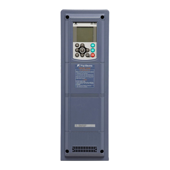
Thank you for purchasing our FRENIC-HVAC series of inverters.
• This product is designed to drive a three-phase induction motor. Read through this manual to become
familiar with the handling procedure and correct use.
• Improper handling might result in incorrect operation, short life cycle, or failure of this product as well as the
motor.
• Deliver this manual to the end user of this product. Keep this manual in a safe place until this product is
discarded.
• For instructions on how to use an optional device, refer to the instruction and installation manuals for that
optional device.
Fuji Electric Co., Ltd.
Instruction Manual
INR-SI47-1610-E
Advertisement
Table of Contents

Related Manuals for Fuji Electric frenic-hvac


Summary of Contents for Fuji Electric frenic-hvac
- Page 1 Instruction Manual Thank you for purchasing our FRENIC-HVAC series of inverters. • This product is designed to drive a three-phase induction motor. Read through this manual to become familiar with the handling procedure and correct use. • Improper handling might result in incorrect operation, short life cycle, or failure of this product as well as the motor.
- Page 2 Copyright © 2011 Fuji Electric Co., Ltd. All rights reserved. No part of this publication may be reproduced or copied without prior written permission from Fuji Electric Co., Ltd. All products and company names mentioned in this manual are trademarks or registered trademarks of their respective holders.
-
Page 3: Safety Precautions
Preface Thank you for purchasing our FRENIC-HVAC series of inverters. This product is designed to drive a three-phase induction motor. This instruction manual provides only minimum requisite information for wiring and operation of the product. Read through this manual before use. - Page 4 • Do not support the inverter by its front cover during transportation. Doing so could cause a drop of the inverter and injuries. • Prevent lint, paper fibers, sawdust, dust, metallic chips, or other foreign materials from getting into the inverter or from accumulating on the heat sink.
- Page 5 • In general, sheaths of the control signal wires are not specifically designed to withstand a high voltage (i.e., reinforced insulation is not applied). Therefore, if a control signal wire comes into direct contact with a live conductor of the main circuit, the insulation of the sheath might break down, which would expose the signal wire to a high voltage of the main circuit.
- Page 6 Design the machinery or equipment so that human safety is ensured after restarting. • If the user configures the function codes wrongly without completely understanding this Instruction Manual and the FRENIC-HVAC User's Manual, the motor may rotate with a torque or at a speed not permitted for the machine.
- Page 7 Maintenance and inspection, and parts replacement • Before proceeding to maintenance or inspection, turn OFF the power and wait at least 10 minutes. Further, make sure, using a multimeter or a similar instrument, that the DC link bus voltage between the terminals P(+) and N(-) has dropped to the safe level (+25 VDC or below).
-
Page 8: Frn0.75Ar1
Conformity to the Low Voltage Directive in the EU If installed according to the guidelines given below, inverters marked with CE are considered as compliant with the Low Voltage Directive 2006/95/EC. Compliance with European Standards Adjustable speed electrical power drive systems (PDS). Part 5-1: Safety requirements. - Page 9 Conformity to the Low Voltage Directive in the EU (Continued) 9. Use wires listed in EN60204 Appendix C. Recommended wire size (mm MCCB or Main terminal RCD/ELCB Aux. Main power input Inverter type control Inverter Control Rated outputs power [L1/R, L2/S, Inverter’s circuit current...
- Page 10 Conformity with UL standards and CSA standards (cUL-listed for Canada) UL/cUL-listed inverters are subject to the regulations set forth by the UL standards and CSA standards (cUL-listed for Canada) by installation within precautions listed below. 1. Solid state motor overload protection (motor protection by electronic thermal overload relay) is provided in each model.
- Page 11 Conformity with UL standards and CSA standards (cUL-listed for Canada) (continued) 7. Install UL certified fuses or circuit breaker between the power supply and the inverter, referring to the table below. Required torque lb-in (N•m) Inverter type Aux. control Main terminal Control circuit power supply ̈...
- Page 12 Conformity with UL standards and CSA standards (cUL-listed for Canada) (continued) Wire size AWG (mm Main terminal L1/R,L2/S,L3/T * U,V,W * Inverter type 75°C 75°C wire wire ̈ 0.75 FRN0.75AR1 -4¸ ̈ FRN1.5AR1 -4¸ ̈ FRN2.2AR1 -4¸ ̈ (2.1) FRN3.7AR1 ̈...
-
Page 13: Table Of Contents
8.4.2 Compliance with EN61000-3-2 ...... 8-3 8.4.3 Compliance with EN61000-3-12 ....8-3 8.5 Compliance with UL Standards and Canadian Standards (cUL certification)........8-3 8.5.1 General comments ........8-3 8.5.2 Considerations when using FRENIC-HVAC in systems to be certified by UL and cUL ..8-3... -
Page 15: Chapter 1 Before Use
In this manual, inverter types are denoted as "FRN_ _ _AR1 -4¸." The boxes alphabetic letters depending on the enclosure and shipping destination, respectively. If you suspect the product is not working properly or if you have any questions about your product, contact your Fuji Electric representative. -
Page 16: Chapter 2 Mounting And Wiring The Inverter
Chapter 2 MOUNTING AND WIRING THE INVERTER 2.1 Installing the Inverter (1) Mounting base Install the inverter on a base made of metal or other non-flammable material. Do not mount the inverter upside down or horizontally. (2) Clearances Ensure that the minimum clearances indicated in Figure 2.1 and Table 2.1 are maintained at all times. -
Page 17: Wiring
2.2 Wiring Before wiring, remove the front cover and wiring plate and then set cable glands or conduits on the wiring plate. After wiring, mount the wiring plate and front cover back into place. (The cable glands or conduits should be prepared by the customer.) 2.2.1 Removing and mounting the front cover and the wiring plate (1) Removing the front cover and the wiring plate... -
Page 18: Recommended Wire Sizes
2.2.2 Recommended wire sizes For the recommended wire sizes for the main circuits, refer to the "Conformity to the Low Voltage Directive in the EU" and "Conformity with UL standards and CSA standards (cUL-listed for Canada)" given in Preface. 2.2.3 Terminal arrangement diagrams and screw specifications The tables and figures given below show the screw specifications and terminal arrangement diagrams. - Page 19 Arrangement of control circuit terminals ̈ Screw type of terminal block ̈ Europe type of terminal block (common to all inverter types) (common to all inverter types) Table 2.3 Control Circuit Terminals Screw specifications Wire strip length Terminal Recommended Type of screwdriver Gauge No.
-
Page 20: Terminal Functions And Wiring Order
(Note) DC link bus terminals P(+), N(-) When you need to use the DC link bus terminals P(+) and N(-), consult your Fuji Electric representative. The three-phase input power lines are connected to these terminals. (*2) Main circuit power input... - Page 21 Table 2.5 Names, Symbols and Functions of the Control Circuit Terminals (Continued) Classifi- Name Symbol Functions cation Digital input 1 to [X1] (1) Various signals such as "Coast to a stop," "Enable external Digital input 7 alarm trip," and "Select multi-frequency" can be assigned to [X7] terminals [X1] to [X7], [FWD] and [REV] by setting function codes E01 to E07, E98, and E99.
-
Page 22: Connection Diagrams
2.2.5 Connection diagrams This section shows connection diagrams with the Enable input function used. SINK mode input by factory default... - Page 23 SOURCE mode input by factory default...
- Page 24 *1 Install a recommended molded case circuit breaker (MCCB) or residual-current-operated protective device (RCD)/earth leakage circuit breaker (ELCB) (with overcurrent protection function) in the primary circuit of the inverter to protect wiring. Ensure that the circuit breaker capacity is equivalent to or lower than the recommended capacity. *2 Install a magnetic contactor (MC) for each inverter to separate the inverter from the power supply, apart from the MCCB or RCD/ELCB, when necessary.
-
Page 25: Setting Up The Slide Switches
2.2.6 Setting up the slide switches Switching the slide switches located on the control PCB (see Figure 2.4) allows you to customize the operation mode of the analog output terminals, digital I/O terminals, and communications ports. To access the slide switches, remove the front cover so that you can see the control PCB. For details on how to remove the front cover, refer to Section 2.2.1. -
Page 26: Chapter 3 Names And Functions Of Keypad Components
Chapter 3 NAMES AND FUNCTIONS OF KEYPAD COMPONENTS LED Indicators These indicators show the current running status of the inverter. STATUS (green): Running state WARN. (yellow): Light alarm state ALARM (red): Alarm (heavy alarm) state LCD Monitor This monitor shows the following various information about the inverter according to the operation modes. -
Page 27: Chapter 4 Running The Motor For A Test
Chapter 4 RUNNING THE MOTOR FOR A TEST 4.1 Checking Prior to Powering ON Check the following before powering on the inverter. (1) Check that the wiring is correct. Especially check the wiring to the inverter input terminals L1/R, L2/S and L3/T and output terminals U, V, and W. -
Page 28: Configuring The Function Code Data Before Test Run
4.3 Configuring the Function Code Data Before Test Run Configure the function codes listed below according to the motor ratings and your machinery design values. For the motor ratings, check the ratings printed on the motor's nameplate. For your machinery design values, ask system designers about them. -
Page 29: Chapter 5 Troubleshooting
Chapter 5 TROUBLESHOOTING 5.1 Alarm Codes Table 5.1 Quick List of Alarm Codes Code Name Description The inverter momentary output current exceeded the overcurrent level. Instantaneous overcurrent : Overcurrent during acceleration : Overcurrent during deceleration : Overcurrent during running at a constant speed The DC link bus voltage exceeded the overvoltage detection level. -
Page 30: Chapter 6 Maintenance And Inspection
Chapter 6 MAINTENANCE AND INSPECTION Perform daily and periodic inspections to avoid trouble and keep reliable operation of the inverter for a long time. 6.1 Daily Inspection Visually inspect the inverter for operation errors from the outside without removing the covers when the inverter is ON or operating. - Page 31 Table 6.1 List of Periodic Inspections (Continued) Check part Check item How to inspect Evaluation criteria Terminal Check that the terminal blocks are not Visual inspection No abnormalities blocks damaged. 1) Check for electrolyte leakage, 1), 2) 1), 2) DC link bus discoloration, cracks and swelling capacitor Visual inspection...
-
Page 32: List Of Periodic Replacement Parts
Standard replacement intervals mentioned above are only a guide for replacement, not a guaranteed service life. 6.4 Inquiries about Product and Guarantee 6.4.1 When making an inquiry Upon breakage of the product, uncertainties, failure or inquiries, inform your Fuji Electric representative of the following information. Inverter type (Refer to Chapter 1, Section 1.1.) SER No. -
Page 33: Chapter 7 Specifications
Chapter 7 SPECIFICATIONS 7.1 Standard Model Three-phase 400 V class series Item Specifications ̈- Type (FRN_ _ _AR1 4¸) 0.75 18.5 (4.0) Nominal applied motor (kW) 0.75 18.5 (4.0) Rated capacity (kVA) Output ratings Rated current (A) 13.5 18.5 24.5 Rated current (A) 10.3 13.9... -
Page 34: External Dimensions
7.2 External Dimensions Dimensions (mm) Rated voltage Inverter type Figure A Figure B φA FRN0.75AR1̈-4¸ FRN1.5AR1̈-4¸ FRN2.2AR1̈-4¸ FRN3.7AR1̈-4¸ FRN4.0AR1̈-4E FRN5.5AR1̈-4¸ Three-phase FRN7.5AR1̈-4¸ 400V FRN11AR1̈-4¸ FRN15AR1̈-4¸ FRN18.5AR1̈-4¸ FRN22AR1̈-4¸ FRN30AR1̈-4¸ FRN37AR1̈-4¸ 4.0 kW for the EU. The inverter type is FRN4.0AR1̈-4E. Note A box ( ̈ ) replaces an alphabetic letter depending on the enclosure. A box ( ¸... -
Page 35: Chapter 8 Conformity With Standards
Chapter 8 CONFORMITY WITH STANDARDS Compliance with European Standards The CE marking on Fuji products indicates that they comply with the essential requirements of the Electromagnetic Compatibility (EMC) Directive 2004/108/EC and Low Voltage Directive 2006/95/EC which are issued by the Council of the European Communities. The products comply with the following standards Low Voltage Directive EN61800-5-1: 2007... -
Page 36: Leakage Current Of The Emc Filter
Inverters of 11 to 37 kW: When shielded wires are not used for the motor cable, remove the motor cable clamps to prevent the cable covering from getting damaged, which makes the machinery or equipment incompliant with the EMC standards. Removing a ferrite core from the input lines in wiring does not affect inverter running. -
Page 37: Harmonic Component Regulation In The Eu
8.5.2 Considerations when using FRENIC-HVAC in systems to be certified by UL and cUL If you want to use the FRENIC-HVAC series of inverters as a part of UL Standards or CSA Standards (cUL certified) certified product, refer to the related guidelines described on pages viii to x. - Page 38 In no event will Fuji Electric Co., Ltd. be liable for any direct or indirect damages resulting from the application of the information in this manual.
- Page 39 Fuji Electric Co., Ltd. Gate City Ohsaki, East Tower, 11-2, Osaki 1-chome, Shinagawa-ku, Tokyo 141-0032, Japan Phone: +81 3 5435 7058 Fax: +81 3 5435 7420 http://www.fujielectric.com/...
Need help?
Do you have a question about the frenic-hvac and is the answer not in the manual?
Questions and answers