Table of Contents
Advertisement
Advertisement
Table of Contents
Troubleshooting

Subscribe to Our Youtube Channel
Related Manuals for Belarus 80.1


Summary of Contents for Belarus 80.1
- Page 1 BELARUS 80.1/82.1/820 80-0000010B OM OPERATION MANUAL 2015...
- Page 2 In view of Minsk Tractor Works policy directed to constant upgrading of produced goods, the construction of some units and parts of Belarus tractor may undergo changes which are not reflected in present edition. The detailed information may be obtained from “BELARUS”...
-
Page 3: Table Of Contents
…………………………………………………………………39 2.13.3 Gear shifting in transmission with mechanical gearbox and reverse-reduction gear……….….………………………………………………………………………………….. 41 2.14 Front driving axle drive control on tractors “BELARUS-82.1/820”………………….. 43 2.15 Power take-off shafts control……………. …………………………..……………….. 44 2.15.1 General information……………………………………………………………………. 44 2.15.2 Rear power take-off shaft control………………..……….………………………….. 44 2.15.3 Side semi-continuous power take-off shaft control……………………..…...…….. - Page 4 2.28.8 Control of RLL locking mechanism in transport position on tractors BELARUS 80.1/82.1 with canopy frame or canopy base on the basis of small cabin………………. 82 2.28.9 Operation of rear lift linkage with draft control of tractors with canopy frame or canopy base on the basis of a small cabin ……………………………….…………………...
- Page 5 80-0000010B OM 3.1.1.1 General information…………………………………………………………..………. 89 3.1.1.2 Engine components………….……………………………………………………….. 90 3.1.2 Engine air cleaning system……………………………………..……………………… 94 3.1.3 External part of engine cooling system…………..…………………………………… 95 3.2 Clutch……..…………………………..………………………………………….…………. 96 3.2.1 Clutch coupling…..………………………………..…………………………….………. 96 3.2.2 Peculiarities of clutch coupling dismounting, mounting and adjustment…...…..…… 97 3.2.2.1 General information………………………..……………………………………..…..
- Page 6 3.10.3.2.2 Transfer gearbox control on tractors BELARUS-82.1/820 with universal cabin (canopy frame or canopy base on the basis of universal cabin)…………………... 151 3.10.3.2.3 Transfer gearbox control on tractors BELARUS-82.1 with canopy frame or canopy base on the basis of small cabin…………..……………..…………………………. 152 3.10.3.3 Adjustment of the control link of the FDA drive transfer box…………..……..
- Page 7 80-0000010B OM 3.16.2.1 Buckles...……….…….………………………………………………………………. 181 3.16.2.1.1 General information……………….………………………………………………. 181 3.16.2.1.2 Telescopic buckles ……………………………………………………………….. 181 3.16.2.1.3 External turnbuckles………………………………………………………………. 183 3.16.2.1.4 Internal buckles……….…………………………………………………………… 184 3.16.2.2 Lifting rod….………………………………………………………………………….. 185 3.16.2.3 Upper link……..……………………………………………………………………..186 3.16.2.4 Lower links…….………………………………………………………………………187 3.16.2.4.1 General information……………………………………………………………….. 187 3.16.2.4.2 Installation in working position of crossbar and rear ends of detachable lower links ………………………….…………………………………………………………...
- Page 8 80-0000010B OM 4 INTENDED USE OF TRACTOR ………………………..……………………………..215 4.1 Safety measures while preparing tractor for operation…..…………………………… 215 4.2 Tractor use …………………..…………………………………………………………….. 216 4.2.1 Boarding the tractor...………………………………………………………………..216 4.2.2 Preparing for engine start and starting the engine …………………...……..……… 216 4.2.2.1 General instructions…………………………………………………………………... 216 4.2.2.2 Preparing for engine start and starting the engine………………………………..
- Page 9 267 5.10 Possibility of front loader installation…………………..……………………………..269 5.10.1 General information….………………………………………………………………… 269 5.10.2 Safety measures to be taken when operating tractors BELARUS-80.1/82.1/820 with loader installed……………………………………………………………………………. 271 5.10.3 Information on the tractor mounting holes…………………………………………... 273 6 TECHNICAL MAINTENANCE…………..……………………………..……………………275 6.1 General instructions………………………………………………………………..………...
- Page 10 ANNEX B (compulsory) – Electric circuit diagram of tractors “BELARUS – 80.1/82.1/820” electrical equipment connections (dashboard with molded panel)…...…………………..…. 380 ANNEX C (compulsory) – Electric circuit diagram of tractors “BELARUS – 80.1/82.1” elec- trical equipment connections with tent frame or tent base on the basis of small cabin……. 381...
- Page 11 80-0000010B OM Introduction The present manual is intended for studying the structure, operation rules and maintenance of tractors “BELARUS- 80.1/82.1/820 ”. Scrutinize this manual. It will help you to study the rules of correct operation and maintenance. Failure to follow this instruction can lead to operator's injury or a breakdown of a tractor or to inflicting damage to the third persons.
- Page 12 80-0000010B OM The manufacturer uses standard international symbols, regarding application of instru- ments and control units. Given below are the symbols with indication of their meanings. — see the manual; — control manipulations; — brake; — fast; — manual brake; —...
-
Page 13: Tractor Description And Operation
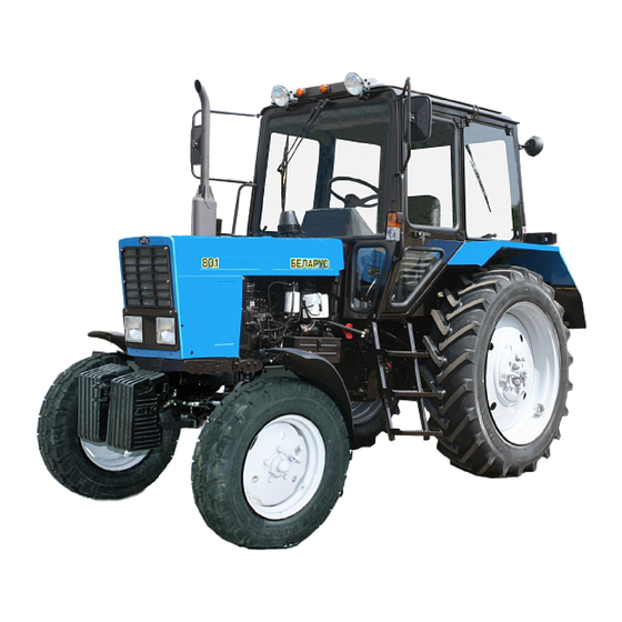
80-0000010B OM 1 Tractor description and operation 1.1 Assignment of tractor Tractors “BELARUS- 80.1/82.1/820” are intended for performance of various gen- eral–purpose agricultural operations with mounted, semi-mounted and trailed machines and implements, for loading-unloading works and transportation works in plant growing and cattle breeding. - Page 14 80-0000010B OM Figure 1.1.1 – Tractor “BELRUS-80.1” Figure 1.1.2 – Tractor “BELARUS-82.1” (the rest is in figure 1.1.1)
- Page 15 80-0000010B OM Figure 1.1.3 – Tractor “BELARUS-820”...
- Page 16 Figure 1.1.4 – Tractors “BELARUS-80.1/82.1/820” with canopy base and canopy frame on the basis of a universal cabin (the rest is in figure 1.1.1 for “BELARUS-80.1”, in figure 1.1.2 for “BELARUS-82.1” and in figure 1.1.4 for “BELARUS-820”) а) canopy base...
-
Page 17: Technical Specifications
80-0000010B OM 1.2 Technical specifications Basic parameters and technical specifications of the tractors “BELARUS- 80.1/82.1/820” are given in table 1.2.1. Table 1.2.1 Parameter Parameter value for tractor (characteristics) title 80.1 82.1 1 Traction class as per GOST 27021: 2 Rated traction force, kN: 3 Engine а) model:... - Page 18 80-0000010B OM Table 1.2.1 continued Parameter Parameter value for tractor (characteristics) title 80.1 82.1 7 Tractor travel speed (calculat- ed) at rated engine crankshaft speed, on tyres of basic configu- ration, km/h: а) for forward motion: 1) least: 1,94 1,94...
- Page 19 80-0000010B OM Table 1.2.1 continued Parameter Parameter value for tractor (characteristics) title 80.1 82.1 14 Least radius of turning circle with smallest track with braking of rear inner wheel, m: 15 Tractor base, mm: 2370±20 2450±20 2450±20 16 Maximum fordable depth, m:...
- Page 20 80-0000010B OM Table 1.2.1 finished Parameter Parameter value for tractor (characteristics) title 80.1 82.1 22 Working equipment: а) rear power take-off shaft: 1) rated speed of PTO shaft end with the continuous drive on, min - position I (under the engine...
-
Page 21: Tractor Composition
The front driving axle has an axle drive gear, self-locking differential, final gears. On tractor “BELARUS-82.1” it is with bevel wheel gear group. On tractor “BELARUS-820” it is with planetary spur wheel gear group. The front driving axle drive is a transfer box with au- tomatic engagement of the FDA, two cardan shafts and intermediate bearing with safety coupling. - Page 22 - hydrostatic with dosing pump on the body of power steering (optionally on tractor “BELARUS-80.1” with canopy frame or canopy base on the basis of a small cabin). The feeding pump is of gear-type. The direction of rotation is left. The dosing pump is gerotor- type, with an open center, without steering response.
-
Page 23: Vibration Level At The Operator's Working Place Of The Tractor
0,800 1,620 3,200 6,380 12,760 tion, m/s Maximum permissible local vibration levels on controls of tractors “BELARUS- 80.1/82.1/820” are presented in table 1.4.3. Table 1.4.3 Parameter title Parameter value in octave band with geometric mean frequency, Hz Octave band, Hz... -
Page 24: Controls And Instruments
80-0000010B OM 2 Controls and instruments 2.1 Layout of controls and instruments of the tractor Controls and instruments, located in the tractor cabin (universal) are shown in fig- ures 2.1.1 and 2.1.2. 1 – emergency flashing switch; 2 – hand wheel to control engine water radiator wind shutter;... - Page 25 - instead of handles to control HLL outlets against order a joystick and a lever to con- trol HLL outlets can be installed; - installation of a creeper is possible; - on tractors “BELARUS-82.1” instead of FDA 72 FDA 822 can be installed; - on tractors “BELARUS- 80.1/82.1” instead of HSC HPS can be installed.
-
Page 26: Switches Of The Instrument Board
80-0000010B OM 2.2 Switches of the instrument dashboard Switches of the instrument dashboard are shown in figure 2.2.1 . 1 – multifunctional underwheel switch; 2 – emergency flashing switch; 3 – central light switch; 4 – windscreen washer switch; 5 – starter and instruments switch. Figure 2.2.1 –... - Page 27 80-0000010B OM - as you move the lever of the switch 1 from the lower beam position up against the stop, the upper beam turns on for a short time (“upper beam blinking, non-fixed position) irre- spective of the position of the central light switch. As you release the lever it will automati- cally return to the lower beam position.
-
Page 28: Upper Dashboard Unit Of Button Switches And Rear Window Wiper Switch
80-0000010B OM 2.3 Upper dashboard unit of button switches and rear window wiper switch Pressing switch button 1 (figure 2.3.1) turns on the windscreen wiper. The switch has got three positions: “Off”; “On with low speed”; “On with high speed”. Pressing switch button 2 (Figure 2.3.1) turns on air ventilation in the cab. -
Page 29: Cab Heater And Fan Control
80-0000010B OM 2.4 Cab heater fan control Elements of heater fan control are shown in figure 2.4.1. 1, 2 – heater valve handle; 3 – recirculation screen; 4 – cab fan switch; 5 – deflector; 6 – hose; 7 – clamp; 8 – drain plug. Figure 2.4.1 –... - Page 30 80-0000010B OM - tighten plugs 8, first loosen clamps 7 and then disconnect hoses 6 from the left and right sides of the cabin; - blow off the system with compressed air; - after blowing off close the heater valve, by turning handle 1 clockwise against the stop, connect hoses 6 and tighten clamps 7;...
-
Page 31: Instrument Board
80-0000010B OM 2.5 Instrument board The Instrument board 4 (figure 2.1.1) includes five indicators with five pilot lamps, as shown in figure 2.5.1. 1 – backup fuel level in tank warning lamp; 2 – air pressure in the pneumatic system indicator;... - Page 32 80-0000010B OM 2.5.3 Level in tank indicator scale 4 (figure 2.5.1) has divisions “0–1/4–1/2–3/4–1” (option 1), or “0–0,5–1” (option 2). In the indicator scale warning lamp 1 is built in (orange color), which lights up when fuel level in the tank decreases to 1/8 of the total tank volume. ATTENTION: DO NOT ALLOW USE OF FUEL TO THE CONDITION OF “DRY TANK”...
-
Page 33: Pilot Lamps Unit
HSC system drops below 0.08 MPa (periodical lighting up of lamp 6 is allowed at minimum engine speed – when the engine speed rises, lamp 6 should go out). If HPS is in- stalled instead of HSC on the tractors “BELARUS-80.1/82.1”, pilot lamp 6 is not used. -
Page 34: Tachospeedometer
- rear PTO revolutions; - speed sensors operating capacity; - overvoltage in the tractor on-board network annunciation. Tachospeedometer АР70.381 can be installed on tractors “BELARUS-80.1/82.1/820” or combined undicator unit КД 8083. 2.7.2 Tachospeedometer АР70.3813 Tachospeedometer АР70.3813 is shown in figure 2.7.1. -
Page 35: Multifunctional Indicator Unit Кд 8083
80-0000010B OM 2.7.3 Multifunctional indicator unit КД 8083 The multifunctional indicator unit КД 8083 is shown in figure 2.7.2. 1 – annunciator of overvoltage in the tractor on-board network (red color); 2 – indicator of engine speed (needle indicator); 3 – indicator of rear PTO revolutions in 1000 min-1 mode (light indicator);... -
Page 36: Steering
2.8 Steering 2.8.1 General information Tractors “BELARUS-80.1/82.1/820” are equipped with hydrostatic steering control (HSC). Upon request tractors “BELARUS-80.1/82.1” can be equipped with HPS instead of HSC. 2.8.2 Steering wheel adjustments The steering wheel has the following adjustments: - height adjustment, along steering shaft axis. -
Page 37: Parking Brake Control
80-0000010B OM 2.9 Parking brake control Upper position of handle 1 (figure 2.9.1) – parking brake “On”. Lower position of handle 1 – parking brake “Off”. To disengage the parking brake press button “A” of control lever and let lever 1 down against the stop. - Page 38 The rear axle differential lock is used for short-term locking of rear wheels when overcom- ing obstacles. When HPS instead of HSC is installed on tractors “BELARUS-80.1/82.1” there is no pedal 24. To control the differential lock instead of pedal 24 handle 29 is installed, which has the following positions: - “DL off”...
-
Page 39: Shifting Of Gears
(GB 18F+4R). Upon request tractors “BELARUS- 80.1/82.1/820 can be equipped with the following transmis- sions configurations: - with mechanical gearbox and a synchronized gear reduction unit (GB 18F+4R);... - Page 40 2.13.2. Figure 2.13.2 The velocity diagram of tractors “BELARUS-80.1/82.1” on rear tyres 15.5R38 and “BELARUS-820” on rear tyres 18.4R34(F-11) ATTENTION: GEARS AND RANGES SHIFTING IS CARRIED OUT ONLY ON THE...
-
Page 41: Gear Shifting In Transmission With Mechanical Gearbox And Reverse-Reduction
80-0000010B OM 2.13.3 Gear shifting in transmission with mechanical gearbox and reverse-reduction gear Control elements of the gearbox with the reverse-reduction gear are shown in figure 2.13.3. 1 – diagram of gearbox reverse-reduction gear stages shifting; 2 – lever to control gearbox reverse-reduction gear;... - Page 42 (gear ratio 1,89) is mounted on the right glass of the cabin and is shown in figure 2.13.5. Figure 2.13.5 The velocity diagram of tractors “BELARUS- 80.1/82.1” on rear tyres 15.5R38 and “BELARUS-820” on rear tires 18.4R34(F-11), equipped with the gearbox with reverse-reduction gear (gear ratio 1,89) Upon request the mechanical creeper MHU-05 (МХУ-05) can be installed on your tractor or...
-
Page 43: Front Driving Axle Drive Control On Tractors "Belarus-82.1/820
80-0000010B OM 2.14 Front driving axle drive control on tractors “BELARUS-82.1/820” FDA drive control handle 1 (figure 2.14.1) has three fixed positions: - "FDA off“– lower most (front) position. This position is used during hauling opera- tions on hard-surface roads;... -
Page 44: Power Take-Off Shafts Control
80-0000010B OM 2.15 Power take-off shafts control 2.15.1 General information On tractors “BELARUS-80.1/82.1/820” of basic configuration rear power take-off shaft is mounted: Upon request a side –semi-continuous PTO can be mounted. Additional information, on the rules of operation with power take-off shaft, which is not included in present subsection 2.15, are given in subsection 4.2.7 “PTO use”... -
Page 45: Side Semi-Continuous Power Take-Off Shaft Control
80-0000010B OM 2.15.2.3 Two-speed continuous drive of rear PTO switch Arm 2 (Figure 2.16.1) of the continuous drive has 2 positions: I - 540 min — full shift position, clockwise; II - 1000 min — full shift position anticlockwise. In order to select the required PTO shaft rotation speed unscrew one turn bolt 1, shift arm 2 to the position “I”... -
Page 46: Hydraulic Lift Linkage Control
HLL control elements include handles to control remote cylinders and RLL, HLL pump control parts and lever to lock RLL mechanism in transport position. On tractors “BELARUS-80.1/82.1/820” the following distributors can be installed: - Р80-3/1-222 (without draft control); - Р80-3/4-111 (with draft control);... -
Page 47: Remote Hydraulic Cylinders Control
80-0000010B OM 1 – roller to switch on HLL pump; 2 – bolt; 3 – diagram of HLL pump switching on. Figure 2.16.1 – HLL pump control Note – Position “HLL pump switched off” is shown in figure 2.16.1. ATTENTION: SWITCH ON AND OFF THE HLL PUMP ONLY AT MINIMUM IDLE SPEED OF THE ENGINE! If the HLL defects occur, which result in oil leakage from hydraulic system, switch off the HLL pump when you transport tractor to the repair site. - Page 48 The diagram of layout and connection of the distributor Р80-3/1-222, Р80-3/4- 111(222), РП70-890.1, РП70-1221.1С, РП70-1221ТС outlets to the external consumers on tractors “BELARUS-80.1/82.1/820” is shown in figure 2.16.3. Figure 2.16.3 – The diagram of layout and connection of the distributor Р80-3/1- 222, Р80-3/4-111(222), РП70-890.1, РП70-1221.1С, РП70-1221ТС...
- Page 49 80-0000010B OM 2.16.3.2 Control of the remote hydraulic cylinders with the distributor RS-213 BEL- ARUS installed Each of three handles 1, 2, 3 (figure 2.16.4) of the distributor RS-213 BELARUS has four positions: - “Floating” – upper most fixed position;...
- Page 50 Figure 2.16.7 – Control of the remote hydraulic cylinders with the distributor RS-213 BELARUS installed using joystick and lever The diagram of layout and connection of the distributor РП70-1221ТC outlets to the external consumers on tractors “BELARUS-80.1/82.1/820” is shown in figure 2.16.3.
-
Page 51: Control Of Rll Locking Mechanism In Transport Position On Tractors Without Draft Control
To unlock RLL slightly raise the implement by handle 3 (figure 2.1.2), and turn lever 12 (figure 2.1.2) to the right. 2.16.6 Adjustable implement lift kickout Adjustable implement lift kickout is mounted on tractors “BELARUS-80.1/82.1/820” up- on request. Limit the retraction stroke of the rear cylinder rod of the linkage mechanism (the height of the implement lifting) using adjustable stop 2 (figure 2.16.8) by performing the following op-... -
Page 52: Control Elements Of Rll And Hydraulic Hook Grips Or Lowering Link With Draft Control
2.17.1 Rear lift linkage control On tractors “BELARUS-80.1/82.1/820” draft control is installed, which provides the possibility of draft, position and depth control of agricultural implements position. Operating elements of the draft control, which provides the possibility of draft, posi- tion, and depth control of agricultural implements position, are shown in figure 2.17.1... - Page 53 80-0000010B OM Handwheel of correction speed control 4 serves for adjustment of agricultural im- plement position correction speed during tractor operation. When handwheel 4 is rotated clockwise the correction speed decreases, when rotated anticlockwise it increases. Carry out adjustment of handwheel 4 after you finish adjusting the RLL and mounted implements (plough, tiller etc.).
- Page 54 80-0000010B OM When using position control method draft control automatically maintains the set position of the agricultural implement relative to the tractor frame. Use of position control for soil cultivation with mounted ploughs, tillers for overall and inter-row cultivation of soil, as well as for deep cultivation is recommended in the conditions of smooth field relief.
-
Page 55: Hydraulic Hook Grips Or Lowering Link Control
80-0000010B OM 2.17.2 Hydraulic hook grips or lowering link control Upon request tractor can be equipped with trailed pickup hook (hydraulic hook).The hydraulic hook is designed for working with semi-trailers and agricultural machines on their basis. 1 – handle to control hydraulic hook grips; 2 – operating link; 3 – grips; 4 – hook with axis;... -
Page 56: Electrical Cut-Out Fuses And Relays
80-0000010B OM 2.18 Electrical cut-out fuses and relays 2.18.1 General information Electrical cutout fuses are intended for protection of electrical lines against overloads and short circuit. WARNING: TO AVOID BURNING OF TRACTOR WIRING NEVER USE FUSES WITH CURRENT RATING HIGHER THAN RATING SPECIFIED IN THIS SECTION. IF A FUSE OF- TEN BURNS OUT, FIND OUT THE CAUSE AND ELIMINATE THE FAULT! 2.18.2 Fuses of the instrument dashboard with cast panel Three blocks of electrical circuit cutout fuses are built into the instrument dashboard with cast... -
Page 57: Fuses Of The Instrument Dashboard With Molded Panel
80-0000010B OM Table 2.18.1 – Assignment of fuses of the instrument dashboard with cast panel Number as per Rated cur- Name of protected circuit figure 2.18.2 rent 15 А Brake lights, terminal (6) and terminal (8) of trailer socket 15 А Road train lights (if available), rear working lights, cab light 15 А... - Page 58 80-0000010B OM Fuses, located in the instrument dashboard with molded panel are shown in figure 2.18.4. Figure 2.18.4 – Arrangement of fuses in the instrument dashboard with molded panel Table 2.18.2 – Assignment of fuses of the instrument dashboard with molded panel Number as per Rated cur- Name of the protected circuit...
-
Page 59: Fuses Located On The Hll And Hsc (Hll) Oil Tank Body
Apart from the fuses, located in the instrument dashboard and shown in fig. 2.18.2 and in figure 2.18.4 the on-board circuit of “BELARUS- 80.1/82.1/820” tractors has fuse 3 (figure 2.18.5) of accumulator batteries charging circuit and general power supply of tractor on-board circuit before start (60A fuse) and two suspended fuses 8 of heating plugs (30A each fuse). - Page 60 80-0000010B OM 1, 4 – bolts; 2 – handwheel to control engine water radiator shutter; 3 – screw; 5 – side console. Figure 2.18.6 – Access to electro-magnetic relay, located in the instrument dashboard with cast panel To access electro-magnetic relay in the instrument dashboard on tractors with molded panel remove handwheel 2 (2.18.7) of the engine water radiator shutter control by doing screw 3 out.
- Page 61 80-0000010B OM Figure 2.18.8 – Arrangement of electro-magnetic relays in the instrument dashboard Table 2.18.3 – Assignment of the instrument dashboard relay Number in figure 2.18.8 Assignment of relay Turn relay Consumer power relay after starter and instrument switch Heater lockout relay or heater power Starter start up lockout relay Starter relay Heating plugs control block...
-
Page 62: Cab Locks And Handles
80-0000010B OM 2.19 Cab locks and handles 2.19.1 Cab door locks Left and right doors of tractor cab are secured with locks 4 (figure 2.19.1) from in- side. Lever 5 serves to open the left and right cab doors from inside the cab. Moving lever 5 backward unlocks the door. -
Page 63: Rear Window Opening
80-0000010B OM 2.19.3 Rear window opening To open rear window 2 (figure 2.19.3) turn handle 1 upwards (counterclockwise) and push rear window away. Under the influence of airlifts 3 it will take tilt position. To close the rear window pull handgrip 4 on until the window is fixed in window ap- erture, turn handle 1 clockwise until handle detent aligns with bracket forming. -
Page 64: Seat And Its Adjustments
- adjustment of the backrest tilt angle: a) For the seat “BELARUS 80-6800010” the backrest tilt angle is adjusted by means of handwheel 3 within the range from minus 15° to plus 20°. To increase the backrest tilt angle it is necessary to turn the handwheel clockwise, to decrease it –... -
Page 65: Adjustments Of Seat "Grammer
80-0000010B OM - height adjustment is carried out within the range of 30 mm from the middle position. The seat has three height positions: “lower”, “middle” and “upper”. To move the seat from the “lower” position to the “middle” position or from the “middle” position to the “upper” one it is re- quired to lift the seat up smoothly until the arresting stop goes off (a specific click is heard). -
Page 66: Pneumatic System Compressor Control
80-0000010B OM 2.21 Pneumatic system compressor control Handle to turn pneumatic system compressor 1 on (figure 2.21.1) has two positions: left (the arrow on the handle is directed forward as viewed along tractor movement) – “compressor off”, right (the arrow on the handle is directed backward to tractor cab) – “compressor on”. -
Page 67: Connection Of Additional Electrical Equipment Of Coupled Machines
80-0000010B OM 2.22.2 Connection of additional electrical equipment of coupled machines To monitor the working process of coupled machines it is allowed to install monitor- ing equipment (control consoles) in the tractor cabin, which is an accessory of the coupled machine. -
Page 68: Fuel Tank Valves Control
80-0000010B OM 2.23 Fuel tank valves control 1, 7 – valve; 2, 6 – drain fitting; 3, 4 – tank; 5 – line of fuel supply into the engine; 8 – fuel line, connecting fuel tanks. Figure 2.23.1 – Fuel tank valves control Fuel intake into the engine can be carried out from tank 3 (figure 2.23.10) or from tank 4 or from the two tanks simultaneously. -
Page 69: Layout Of Instruments And Controls Of Tractor With Molded Panel Of Instrument Dash-Board
80-0000010B OM 2.24 Layout of instruments and controls of tractor with molded panel of in- strument dashboard Instruments and controls, located in tractor cabin are shown in figure 2.24.1. 1 – multifunctional underwheel switch; 2 – emergency flashing switch; 3 – combina- tion of instruments;... - Page 70 80-0000010B OM Underwheel multifunctional switch 1 (figure 2.24.1) provides turn indicators switch- ing, headlight switching (upper, lower), headlight upper beam flashing, audible beep: - turning lever of underwheel switch 1 away from yourself or towards yourself right or left turn indicator turns on accordingly. After tractor turning the lever automati- cally returns into the initial position.
-
Page 71: Pilot Lamps Unit Of Tractors With Dashboard With Molded Panel
HSC hydraulic system drops below 0,08 MPa (recurrent lighting up of lamp 2 is permissible at minimum engine speed – when engine speed increases lamp 2 has to go out). With the HPS installed instead of the HSC on tractors “BELARUS- 80.1/82.1” pilot lamp 2 is not available;... -
Page 72: Multifunctional Indicator Unit Of Tractors With Dashboard With Molded Panel
80-0000010B OM 2.26 Multifunctional indicator unit of tractors with dashboard with molded panel 2.26.1 General information Multifunctional indicator unit 5 (figure 2.24.1) (further – MIU) and programming console (further PC) of multifunctional indicator unit 7 display the information about operation parameters of tractor systems and components and provide data to the operator about failures or break- downs of some system. - Page 73 80-0000010B OM On tractors “BELARUS-80.1/82.1/820” signal for engine speed calculation is a al- ternator phase winding (terminal “W”). Rotation range indication is from 0 to 3500 (min c) 3 (figure 2.26.1) – PTO speed indicator displays on light indicator power take-off shaft speed.
-
Page 74: Pilot Lamps Of Multifunctional Indicator Unit
80-0000010B OM 1. Total astronomical engine operating time in hours. The sensor accumulates information about total engine op- erating time by the alternator phase winding signal and stores it when the power is off. The indications range is from 0 to 99999 engine run hours. 2. -
Page 75: Creeper Control
The creeper is designated to be installed on tractors, operating with machines which require low gears. On tractors “BELARUS-80.1/82.1/820 equipped with the gear reduction unit in the transmission a mechanical creeper MHU-05 (МХУ-05) can be installed or hydraulic creeper GHU-05 (ГХУ-05). -
Page 76: Py-Frame Or Canopy Base On The Basis Of Small Cabin
80-0000010B OM 2.28 Distinctive features of instruments and controls of tractors “BELARUS- 80.1/82.1” with canopy frame or canopy base on the basis of a small cabin 2.28.1 Layout of controls and instruments of tractors with canopy frame and canopy base on the basis of small cabin Controls and instruments located in the tractor cabin, are shown in figure 2.28.1... -
Page 77: Switches And Selectors Of Instrument Board Of Tractors With Canopy Frame Or Canopy Base On The Basis Of Small Cabin
80-0000010B OM ATTENTION: TRACTORS “BELARUS-80.1/82.1” WITH CANOPY FRAME OR TANE BASE ON THE BASIS OF A SMALL CABIN ARE NOT INTENDED FOR SUPPLIES IN THE COUNTRIES OF CUSTOMS UNION. 2.28.2 Switches and selectors of the instrument dashboard of tractors with canopy frame or canopy base on the basis of small cabin Switches and selectors of the instrument board are shown in figure 2.28.2... - Page 78 TIONS ARE IN THE RED SCALE AREAS IN NORMAL MODE. IF OIL PRESSURE IS TOO LOW OR THERE IS NO OIL PRESSURE, STOP THE ENGINE IMMEDIATELY AND ELIMINATE THE MALFUNCTION. 2.28.3.5 On tractors “BELARUS-80.1/82.1” the mechanical tachospeedometer TX 135 is installed. The tachospeedometer TX 135 displays calculated tractor travel speed on seven scales 1 (figure 2.28.4) depending on the gear engaged 3, 4, 5, 6, 7, 8 or 9 (with the gear...
-
Page 79: Warning And Pilot Lamps Of Tractors With Canopy Frame Or Canopy Base On The Basis Of Small Cabin
2.28.4 Warning and pilot lamps of tractors with canopy frame or canopy base on the ba- sis of small cabin In the instrument dashboard of tractors “BELARUS-80.1/82.1” two warning lamps and two pilot lamps are installed, which are shown in figure 2.28.5 1 –... -
Page 80: Steering Of Tractors With Canopy-Frame Or Canopy Base On The Basis Of Small
2.28.5 Steering of tractors with canopy frame or canopy base on the basis of a small cabin 2.28.5.1 General information Tractors “BLARUS-80.1/82.1” are equipped with a hydraulic power steering and a double-spoke steering wheel. Upon request the hydrostatic steering control with dosing pump on the hydraulic booster housing can be installed on tractor “BELARUS-80.1”. -
Page 81: Fda Drive Control Of Tractors Belarus-82.1 With Canopy Frame Or Canopy Base On The Basis Of Small Cabin
80-0000010B OM 2.28.6 FDA drive control of tractors “BELARUS-82.1” with canopy frame or canopy base on the basis of a small cabin FDA drive control handle 1 (figure 2.28.8) has three fixed positions: - “FDA off” – the lower most position. This position is used during hauling opera- tions on hard-surface roads;... -
Page 82: Rear Power Take-Off Shaft Disengagement Of Tractors With Canopy Frame Or Can
Figure 2.28.9 – Rear PTO control 2.28.8 Control of RLL locking mechanism in transport position on tractors “BELA- RUS-80.1/82.1” with canopy frame or canopy base on the basis of a small cabin 1 – link of RLL locking mechanism in transport position; 2 - RLL Figure 2.28.10 –... -
Page 83: Operation Of Rear Lift Linkage With Draft Control Of Tractors With Canopy Frame Or Canopy Base On The Basis Of A Small Cabin
2.28.9 Operation of rear lift linkage with draft control of tractors with canopy frame or canopy base on the basis of a small cabin. On tractors “BELARUS-80.1/82.1” with canopy frame or canopy base on the basis of a small cabin draft control is installed, which provides a possibility for draft, position, depth control of agricultural implements position. - Page 84 80-0000010B OM 1 – stroke limiter of draft control operating handle; 2 – draft control operating handle; 3 – sector; 4 – spring; 5 – bolt; 6 – switch of draft and position control methods; 7 – hand- wheel of correction speed control; 8 – cover. Figure 2.28.11 –...
- Page 85 80-0000010B OM At the start of the run of cultivated land lower mounted implement, by turning handle 2 (figure 2.28.11) forward. The further forward the handle is set, the greater depth of tillage will be. When you shift handle 2 towards yourself the depth will decrease. After adjusting to the desired depth, shift stroke limiter 1 along the groove of the control console until it stops against the handle and lock it.
-
Page 86: Fuses Of Dashboard Of Tractors With Canopy Frame Or Canopy Base On The Ba
80-0000010B OM Depth control can be used when coupling tractor with mounted implements with supporting wheels. It lies in the fact that the specified cultivation depth is achieved by set- ting the support wheel of coupled implement at a certain height. For depth control set switch 4 (figure 2.28.12) to middle position N, after raising the RLL in the upper most position. -
Page 87: Electro-Magnetic Relays
2.28.11 Electro-magnetic relays On tractors “BELARUS-80.1/82.1” with canopy frame or canopy base on the basis of a small cabin electro-magnetic relays are located in the dashboard and on the HLL oil tank body. Electro-magnetic relays are shown in figures 2.28.15 and 2.28.16. -
Page 88: Seat And Its Adjustment On Tractors Belarus-80.1/82.1 With Canopy Frame Or Canopy Base On The Basis Of Small Cabin
80-0000010B OM 2.28.12 Seat and its adjustments on tractors “BELARUS-80.1/82.1” with canopy frame and canopy base on the bases of a small cabin ATTENTION: BEFORE STARTING TO OPERATE THE TRACTOR ADJUST THE SEAT TO REACH THE MOST COMFORTABLE POSITION. CARRY OUT ALL ADJUST-... -
Page 89: Description And Operation Of Tractor Components
OJSC “MMZ”. On tractors “BELARUS-80.1/82.1/820” the engine Д-243 is installed. Upon request on tractors “BELARUS-80.1/82.1/820” the engine Д-243С can be installed, which accord- ing to hazardous substances emissions complies with ecological requirements of Stage I. The engine Д-243/243С is a four-stroke, piston, four-cylinder internal combustion engine with in-line vertical arrangement of cylinders with direct diesel fuel injection and com- pression ignition. -
Page 90: Engine Components
80-0000010B OM 3.1.1.2 Engine components In accordance with figure 3.1.1 the engine consists of the block of cylinders, cylinder head, crank-and-rod mechanism, valve timing mechanism, as well as components and as- semblies of the power supply, lubrication, cooling, start systems and electrical equipment. 1 –... - Page 91 80-0000010B OM The cylinder block has longitudinal channel, from which oil flows to the main bearings of the crankshaft and bearings of the distributing shaft. On outer surfaces of the cylinder block there are machined mating faces for securing centrifugal oil filter, water pump, coarse and fine fuel filters, oil filler. The main components of the crank-and-rod mechanism are crankshaft 14, pistons 7 with piston rings and pins 4, connecting rods 5, main and connecting rod bearing, flywheel 12.
- Page 92 For air exhaust from the supply system there is a special plug on the filter cover. Air cleaner 8 serves for cleaning air, drawn into the cylinders. Detailed information about composition and operation of intake duct of tractors “BELARUS-80.1/82.1/820” is given in subsection 3.1.2 “Engine air cleaning system”.
- Page 93 For engines start the electric starter is used. On the engines Д-243/243С of tractors “BELARUS-80.1/82.1/820” starters of the rated voltage 12 V are installed. The starter is a direct current electric engine. The starter switch is remote, with the help of electromagnetic relay and starter switch.
-
Page 94: Engine Air Cleaning System
For the engine start an electric starter is used. On the engines Д-243/243С of tractors “BELARUS-80.1/82.1/820” the starter of rated voltage 12 V is installed. The starter is a di- rect current electric motor. Starter switch is remote, with the help of electromagnetic relay starter switch. -
Page 95: External Part Of Engine Cooling System
80-0000010B OM 3.1.3 External part of the engine cooling system The engine cooling system is liquid, of enclosed-type, with forced circulation of the cooling liquid from the centrifugal pump, by the thermostat. It includes a cooling jacket, wa- ter pump, water radiator 7 (figure 3.1.5) with steam-outlet and expansion pipe 16, oil radi- ator 2, connection lines, oil lines 4, fan, expansion tank 5, connection hoses, clamps, drain cock 10, expansion tank plug 6. -
Page 96: Clutch
The driven portion of the clutch includes driven disc 2 (with asbestos free liners) with torque vibration damper 8, mounted on output shaft 6. On tractors “BELARUS-80.1/82.1/820” the necessary force of pressing the rubbing surfaces of the drive and driven portions is provided by nine springs 20. -
Page 97: Peculiarities Of Clutch Coupling Dismounting, Mounting And Adjustment
80-0000010B OM 3.2.2 Peculiarities of clutch coupling dismounting, mounting and adjustment 3.2.2.1 General information 1 – flywheel; 2 – driven disc; 3 – pressure plate; 4 – floating bushing; 5 – release lever; 6 – bearing plate; 7 – locking plate; 8 – adjustment nut; 9 – fork; 10 – bushing. Figure 3.2.2 –... -
Page 98: Dismounting Of Clutch Coupling
80-0000010B OM 3.2.2.2 Dismounting of clutch coupling Dismounting of the clutch coupling is carried out after detachment of the engine from the transmission in the following sequence: - install three technological bolts (M12x40), screwing them in pressure plate 3 (fig- ure 3.2.2) through the technological holes of bearing plate 6;... -
Page 99: Clutch Control
80-0000010B OM 3.2.3 Clutch control 3.2.3.1 General information Clutch control is carried out in the following way: When you press pedal pad 6 (figure 3.2.4) arm 5 shifts and rotates lever 1, connected through control shaft 18 (figure 3.2.1) to the clutch coupling shifter. In this case the clutch dis- engages. -
Page 100: Clutch Casing
80-0000010B OM 3.2.4 Clutch casing The clutch casing of tractors “BELARUS-80.1/82.1/820” can be equipped with a mechanical gear reduction unit (figure 3.2.5), with a reverse reduction gear (figure 3.2.6), with a synchronized gear reduction unit (figure 3.2.7). Clutch casing 7 (figure 3.2.5-3.2.8) can be hypothetically divided into two parts: dry compartment and gear system. - Page 101 80-0000010B OM 1 – flywheel; 2 – floating bushing; 3 – fork; 4 – hub; 5 – release bearing; 6 – shifter bracket; 7 – clutch casing; 8, 9, 12, 13, 15, 25, 29 – bearing; 10 – gear of the HLL pump drive; 11 –...
- Page 102 80-0000010B OM 1 – flywheel; 2 – floating bushing; 3 – fork; 4 – bushing; 5 – release bearing; 6 – shifter bracket; 7 – clutch casing; 8, 9, 12, 13, 15, 27, 31 – bearing; 10 – gear of hydraulic system pump drive; 11 – axis; 14 – output shaft; 16 – drive gear of reverse-reduction gear;...
- Page 103 80-0000010B OM 1 – flywheel; 2 – floating bushing; 3 – fork; 4 – hub; 5 – release bearing; 6 – shifter bracket; 7 – clutch casing; 8, 9, 12, 13, 15, 25, 29 – bearing; 10 – gear of hydraulic system pump drive; 11 – axis; 14 – output shaft; 16 – drive gear of gear reduction unit;...
-
Page 104: Gearbox
GB, its safe engagement and exclusion of self-shutdown). Note: On tractors “BELARUS-80.1/82.1” in configuration with canopy base or cano- py frame on the basis of a small cabin, the range and gears shifting lever of the GB is lo- cated at the center. - Page 105 80-0000010B OM The design of the front part of GB primary shaft of tractors 9F/9R, equipped with the reverse-reduction gear is shown in figure 3.3.2. It has the following differences as com- pared to the above described GB 9F/2R with the mechanical gear reduction unit (figure 3.3.1).
- Page 106 80-0000010B OM If tractor is equipped with the reverse-reduction gear (figure 3.3.4), then there is no intermediate gear of reverse movement 15 (figure 3.3.2) in GB, and tractor reverse move- ment is carried out by turning on the reverse-reduction gear (see. Section 2). In the rear part of shaft 27 on its smooth neck on the bronze bushing driven gear of step-down gears and reverse movement 25 is installed, which is in constant mesh with a smaller gear ring of gear 25 (figure 3.3.1) of intermediate shaft 32.
- Page 107 80-0000010B OM...
- Page 108 80-0000010B OM...
-
Page 109: Gearbox Control
80-0000010B OM 3.3.2.2 Gearbox control GB control consists of fork housing 3 (figure 3.3.1) and GB control cover 15, which are mounted on the upper plane of GB housing 29 and are secured to it by bolts. Fork housing 3 consists of fork of the 1 gear and reverse movement 20 (figure 3.3.2), fork of the 3 and 6... -
Page 110: Gearbox Operation
80-0000010B OM In neutral position of GB control lever 9 extreme positions of its free swinging in transverse plane is determined by limit stop of shaft 2 flattened surface edges into spring- loaded ball 3. These two positions of GB control lever 9 correspond to: to the right from yourself - position of gear lever 4 in the slider slot of fork of the 3 and 6 gears 21, to the... - Page 111 80-0000010B OM On the 2 stage of the range speed reduction unit rotation from intermediate shaft 32 to secondary shaft 6 transmits with deceleration lower, than on the 1 stage. There is no neutral position of drive gear of the 1 stage of speed reduction unit 24 in the range speed reduction unit of the GB, for this reason 1 or 2...
-
Page 112: Distinctive Features Of Design And Operation Of Mechanical Gearbox With Gears And Ranges Shifting Lever Located In The Center
28. By means of the formed engagement power flow from primary shaft 34a transmits to GB intermediate shaft 32. The calculated speeds of tractors “BELARUS-80.1/82.1/820” on all GB gears are given in subsection 2.13 “Shifting of gears”. 3.3.3 Distinctive features of design and operation of mechanical gearbox with gears and ranges shifting lever located in the center Mechanical GB of tractors “BELARUS-80.1/82.1”... - Page 113 80-0000010B OM In cover 16 there is a hole for filling oil in the transmission, which is closed by plug 18. Operation of the mechanical GB with central location of the gears and ranges control lever as well as their operation sequence, is similar to operation and GB control sequence with right location of gears and ranges control lever.
-
Page 114: Reverse-Reduction Gear
80-0000010B OM 3.3.4 Reverse-reduction gear 3.3.4.1 General information Reverse-reduction gear (figure 3.3.4) is tractor assembly unit, formed at the juncture of two components of the transmission: clutch casing 12 and gearbox 10. It is intended for quick change of tractor movement direction from forward movement to reverse and vice versa on all GB gears, which allows tractor to operate in the mode of a “shuttle”. -
Page 115: Mechanical Gear Unit
80-0000010B OM 3.3.4.3 Mechanical gear unit Mechanical gear unit consists of drive gear 19 (figure 3.3.4), driven gear 9, planetary gear 16, intermediate double-crown gear 13 and synchronizer 2. Drive gear of the reverse-reduction gear 19 is mounted in cantilever fashion on splines of output shaft 18. Bearing of output shaft 18 is roller bearing 17, located in cover 20, which is mounted in the clutch casing 12 boring and is se- cured to it by bolts. -
Page 116: Rear Axle
80-0000010B OM 3.4 Rear axle 3.4.1 General information Rear axle shown in figure 3.4.1. consists of the following elements: -main gear; -differential; -final drives. 1 – Drive gear of final drive right; 2 – planetary gear washer; 3 – differential cross; 4 – plane- tary gear;... -
Page 117: Differential
80-0000010B OM shall be within the limits from 30 to 50 N when measured after differential turning 4 … 5 full turns. When tightening bearings it is necessary to turn the differential time after time. The adjustment shall be carried out in the following sequence: - install two sets of adjusting shims under the flange of the right cup, after that tighten bolts with a torque from 80 to 100 N•m;... -
Page 118: Rear Axle Differential Lock
80-0000010B OM 3.4.5 Rear axle differential lock (DL) 3.4.5.1 Differential lock coupling Multi-disc hydraulically operated coupling of differential lock 1 (figure 3.4.2) is located in shell 8, which through the shell of the left two-disc (three-disc) brake and the bearing cup is se- cured by bolts to the rear axle casing. -
Page 119: Rear Axle Differential Lock Control With The Help Of The Pedal
Lock valve-cock 2 (figure 3.12.1) of the differential is built-in in the HSC drain hydraulic line and controls oil flow, supplied to lock coupling. The hydraulic diagram of tractors “BELA- RUS-80.1/82.1/820” lock control is shown in figure 3.12.3. Pedal 1 (figure 3.4.3) of the differential lock control has two positions: - “Lock off”... -
Page 120: Cable Control Of Rear Axle Differential Lock
80-0000010B OM 1 – plug; 2 – valve-cock housing; 3 – bushing; 4 – bracket; 5 – washer; 6 – split pin; 7, 14 – washer; 8, 13, 22 – spring washer; 9, 12, 17, 19, 21 – bolt; 10 – pedal; 11 –... -
Page 121: Rear Axle Differential Lock Cable Control Adjustment
80-0000010B OM - “Differential lock positively on (irrespective of the position of the tractor drive wheels)” – rear most non-fixed position (the valve-cock is turned anticlockwise against the stop). If you release the handle, then the handle and the valve-cock by the action of the spring will return into the position “Differential lock off”... -
Page 122: Rear Power Take-Off Shaft
80-0000010B OM 3.5 Rear power take-off shaft 3.5.1 General information Rear PTO has double-speed continuous and ground-speed drives. The continuous drive is carried out by means of shifting coupling 27, which con- nects crown gear shaft 26 of the PTO planetary reduction gear unit with the GB gear. PTO planetary reduction gear is located in the rear axle casing and consists of crown gear 22, mounted on shaft 26, cover 15 with carrier 25 installed therein with three planetary gears 23, mounted on axles 21 shaft 20, eсcentric axle 3, fixed axle 14 and sun... - Page 123 80-0000010B OM - angular motion of lever 6 under action of spring 7 in both sides from the neutral position shall be from 7 to 10 degrees; - mount plate 7 on adjustment screws 11 (figure 3.5.1) and split pins 3,2x18.019 GOST 397-79;...
-
Page 124: External Adjustment Of Brake Straps
80-0000010B OM 3.5.3 External adjustment of brake straps During operation carry out adjustment of the PTO brake straps if the above given adjustment of backlash in the PTO strap brakes does not lead to elimination of the PTO “slipping” (the margin for adjustment is selected (significant wear of brake strap linings)). When assembling or repairing the rear PTO planetary reduction gear unit at the manufacturing plant eccentric axle 3 (figure 3.5.1) is installed with flattened surface verti- cally at the right and is fixed by lock plate 12 and bolt 13;... -
Page 125: Rear Pto Control On Tractors With Canopy-Frame Or Canopy Base On The Basis Of Small Cabin
80-0000010B OM 3.5.5 Rear PTO control on tractors with canopy frame or canopy base on the basis of a small cabin On tractors with canopy frame and canopy base on the basis of a small cabin me- chanical control of rear PTO is installed. Rear PTO control diagram is shown in figure 3.5.3. -
Page 126: Side Semi-Continuous Power Take-Off Shaft
80-0000010B OM 3.6 Side semi-continuous power take-off shaft To drive coupled machines the side semi-continuous PTO is provided. Place of installation of the side semi-continuous PTO on tractor is shown in figure 3.6.1. 1 – side semi-continuous PTO; 2 – shaft gears of the first gear; 3 – PTO gear. Figure 3.6.1 –... -
Page 127: Brakes
80-0000010B OM 3.7 Brakes 3.7.1 Service brakes and service brakes control Tractors “BELARUS-80.1/82.1/820” are equipped with two-disc service brakes with foot pedal control. The service brakes are mounted on shafts of drive gears of hub drives. The service brakes type is dry. -
Page 128: Check/Adjustment Of Service Brakes Control
80-0000010B OM 1 – friction discs; 2 – stop; 3 – body; 4 – pin; 5 – fork; 6 – link; 7 – stop; 8, 9 – pressure discs; 10 – shaft; 11 – balls. Figure 3.7.2 – Operation principle of the service brakes 3.7.2 Check/adjustment of service brakes control 3.7.2.1 Check the adjustment of the service brakes control. -
Page 129: Parking Brake
80-0000010B OM It is not allowed to reduce brakes pedal travel to less than the values specified in subsection 3.7.3.1, as it leads to premature wear of the friction discs and overheating of the brakes. 1 – locknut; 2 – adjusting bolt; 3 – left pedal; 4 – right pedal Figure 3.7.3 –... -
Page 130: Adjustment Of Parking Brake Control
80-0000010B OM 1 – shaft; 2 – friction discs; 3 – pressure discs; 4 – link; 5 – fork; 6 – pin; 7 – screw; 8 – lock nut; 9 – lever; 10 – ball washer; 11 – bolt; 12 – link; 13 – washer; 14 –... - Page 131 80-0000010B OM - after adjustment tighten locknut 2 of adjusting bolt 3. If the tractor is equipped with trailer brakes pneumatic control system, carry out con- trol of the parking brake in the following way: - set parking brake lever 1 (figure 3.7.6) in the front position (away from yourself); - loosen tightening of locknut 3 of adjusting bolt 3, as well as locknut 6 of link 5 and take out pin 8;...
-
Page 132: Pneumatic System
Upon request tractor configuration can be without pneumatic compressor and without pneumatic equipment. On tractors “BELARUS-80.1/82.1” with canopy frame or canopy base on the basis of a small cabin of basic configuration a pneumatic compressor with a valve is installed. Upon request tractor configuration can be without pneumatic compressor and without pneumatic equipment. -
Page 133: Check And Adjustment Of Pneumatic System Brake Valve Drive
80-0000010B OM 1 – pneumatic compressor; 2 – pressure regulator; 3 – air bleed valve; 4 – air pressure indicator; 5 – condensate drainage valve; 6 – cylinder; 7 – coupling head; 8 – connection pipeline; 9 – pipeline; 10 – pressure sensor; 11 – emergency pressure sensor;... - Page 134 80-0000010B OM 1 – pin; 2 – ferrule; 3 – brake valve; 4 – spring; 5 – link; 6 – nut. Figure 3.8.2 – Adjustment of the pneumatic system brake valve drive Carry out check and, if necessary, adjustment of the pneumatic system brake valve drive in the following way: Connect pressure gage with a scale not less than 1 MPa to coupling head (with black cover) of the tractor pneumatic drive.
-
Page 135: Check And Adjustment Of Pneumatic System Pressure Regulator
80-0000010B OM 3.8.3 Check and adjustment of the pneumatic system pressure regulator Adjustment of pressure of the pneumatic system pressure regulator should be carried out during TM-3, as well as in case of malfunction of the pressure regulator and after dismantling it for washing or replacing worn out parts. -
Page 136: Front Axle 80-3000030 Of Tractor "Belarus-80.1
15, 16 – nut, spring washer; 17, 18 – pins; 19 – oscillation axis; 20 – lock- nut; 21 – ball pin; 22 – protective cover; 23 – upper liner; 24 – joint body; 25 – lower liner; 26 – adjusting plug; 27 – grease fitting. Figure 3.9.1 – Front axle 80-3000030 of tractor “BELARUS-80.1”... -
Page 137: Front Driving Axle
3.10.1 FDA with bevel wheel gear group 3.10.1.1 General information The FDA with bevel wheel gear group is mounted on tractor “BELARUS-82.1”. The front driving axle is intended for transmitting torque to the tractor front driven wheels. The FDA consists of the main gear, the differential and wheel gear group. The main gear is a pair of bevel gears with spiral teeth. -
Page 138: Fda Differential
80-0000010B OM Filling of oil in the FDA beam is carried out up to the lower edge of filler hole through plug 14. Oil drain from the FDA beam is carried out by means of unscrewing drain plug 15 in the FDA body. -
Page 139: Bevel Wheel Gear Group
80-0000010B OM 3.10.1.3 Bevel wheel gear group Wheel gear group is intended to transmit torque from the FDA differential to the drive steering wheels. The composition of the bevel wheeled group is shown in figure 3.10.3. In covers 2 (figure 3.10.1) of the FDA beam the wheel gear group of final drives is installed, consisting of the two bevel gears and pinions –... - Page 140 80-0000010B OM Sealing of the lower bevel gear and pinion is carried out by gasket 4 (figure 3.10.3), ring 10 and shims over the sealing planes of wheel gear group 37 with cover 40 and gas- ket body 5. To prevent dirt entry to working edges of gasket 4 dirt trap 6 is installed. Brackets of front wheel fenders and brackets of steering trapezium 34 (figure 3.10.1) are attached to the wheel gear group housing.
-
Page 141: Adjustment Of Fda With Bevel Wheel Gear Groups
80-0000010B OM 3.10.1.4 Adjustment of FDA with bevel wheel gear groups 3.10.1.4.1 Adjustment of bearings of the main gear drive gear Bearings 26 (figure 3.10.1) shall be adjusted so, that there is no axial play in them, preload not more than 0,05 mm in bearings 26 is allowed. Adjust the bearings in the following sequence: - tighten bearings 26 with nut 25 against the stop. - Page 142 80-0000010B OM 2. Adjust meshing by selecting the required number of split adjusting shims25 be- tween pivot tube flanges 12 and body 17 of the upper bevel gear and pinion. Diametrical shims shall have the same thickness. To check backlash take off cover 15, having drained oil in accordance with subparagraph 6.4.5.10 “Operation 57.
-
Page 143: Fda With Planetary Spur Wheel Gear Groups
3.10.2 FDA with planetary spur wheel gear groups 3.10.2.1 General information FDA with planetary spur wheel gear groups is installed on tractors “BELARUS -820” (on tractor “BELARUS-82.1” upon request). The front driving axle is designed to transmit torque to front steering wheels of the tractor. The FDA consists of the main gear, the dif- ferential and the wheel gear groups. -
Page 144: Wheel Gear Group Of Planetary Spur Type
80-0000010B OM Drive gear of the main gear 36 (figure 3.10.4) is installed in cage 29 on two bevel roller bearings. Preload in bearings is adjusted by means of adjusting washers 30, where- after tightening with nut 33 should be carried out. Driven gear 19 is mounted on splines and centering band of the body of differential 18 and is locked by nut 20 against axial movement. - Page 145 80-0000010B OM Twin joint 24 (figure (3.10.5) is connected to the FDA differential by means of half axle shaft with spline ends 13 (figure 3.10.4) on one side, and on the other side to drive gear 17 (figure 3.10.5) of the spur gear. Drive gear is mounted on two tapered roller bearings 18.
-
Page 146: Adjustments Of Fda With Planetary Spur Wheel Gear Groups
80-0000010B OM 1 – wheel flange; 2, 18, 29 – tapered roller bearing; 3, 20 - gasket; 4 – dirt trap; 5 – planet carrier, 6 – wheel gear group cover; 7 – planetary gears shaft; 8 - rollers; 9 - screw; 10 –... - Page 147 80-0000010B OM - carry out adjustment of meshing of the main gear by installing the corresponding number split adjusting shims 16 between flanges of drive gear cage 15 and FDA body 4. Diametrical shims 16 should have the same thickness. Main gear backlash shall be in the range from 0,18 to 0,46 mm.
- Page 148 80-0000010B OM 3.10.2.3.3 Adjustment of axial play in tapered bearings of the wheel gear group drive gear Axial play in bearings 18 (figure 3.10.5) shall be not more than 0,05 mm. Adjust bearings in the following sequence: - loosen mounting of drive gear cage 22; - by means of disassembling bolts move away drive gear cage 22 and by selecting the required number of adjusting shims 21 adjust axial play in bearings 18.
-
Page 149: Fda Drive
80-0000010B OM 3.10.3 FDA drive 3.10.3.1 Cardan drive The cardan drive is designed to transmit torque from the transfer box to the front drive axle. The cardan drive consists of two cardan shafts (intermediate and front) identical in design and length and an intermediate bearing. The cardan shaft consists of tube 12 (figure 3.10.8) and two joints with cross pieces 17 on needle bearings 13. -
Page 150: Transfer Box
80-0000010B OM Compensation of the front cardan shaft movement when the front drive axle swings is provided by axial movement of flange 1 in bushing 5. To prevent wrapping of straw crops on the cardan shafts during harvesting operations safeguard is provided. 3.10.3.2 Transfer box 3.10.3.2.1 General information 1 - spring;... -
Page 151: Cabin (Canopy Frame Or Canopy Base On The Basis Of Universal Cabin)
4 are located. In working position for wedg- ing each roller is installed by two pins 2 under the action of spiral springs 1. 3.10.3.2.2 Transfer box control on tractors “BELARUS-82.1/820” with a universal cabin (canopy frame or canopy base on the basis of a universal cabin) Toothed coupling 13 control (figure 3.10.9) is carried out by link 4 (figure 3.10.10) through... -
Page 152: Canopy Base On The Basis Of Small Cabin
1 - pin; 2 - fork; 3 - locknut; 4 - link; 5 - bracket; 6 – lock ball; 7 - lever; 8 – guide; 9 – spring; 10 – transfer box; 11 - lever. Figure 3.10.10 – Control of the FDA drive transfer box on tractors “BELARUS- 82.1/820” with a universal cabin (canopy frame or canopy base on the basis of a universal cabin) 3.10.3.2.3 Control of the transfer box on tractor “BELARUS-82.1”... - Page 153 1 – pin; 2 – fork; 3 – locknut; 4 – link; 5 – stop; 6 – strut; 7 – handle; 8 – transfer box; 9 – lever. Figure 3.10.11 – Control of the FDA drive transfer box on tractor “BELARUS- 82.1” with canopy frame or canopy base on the basis of a small cabin...
-
Page 154: Adjustment Of The Control Link Of The Fda Drive Transfer Box
11, which is turned clockwise against the stop. - tighten locknut, install and forelock the pin. 3.10.3.4 Adjustment of control link of the FDA drive transfer box on tractors “BELARUS- 82.1” with canopy frame or canopy base on the basis of a small cabin To adjust the link proceed as follows: - set handle 7 (figure 3.10.11) to the position ”FDA positively engaged”... -
Page 155: Tractor Undercarriage
-7.5-20 – front tyres, in complete set with rear tyres 15.5R38, 16.9R38, 18.4R30, 18.4/78-30 (18.4L-30), 18.4R34(mod. F-11), 9.5-42. On tractor “BELARUS-80.1” with canopy frame or canopy base on the basis of a small cabin in basic configuration the following tyres are mounted: - 9.00 R20 –... - Page 156 Tyres 9.5-42 shall be used only in twin version. Contact your dealer for additional advice on twin tyres application. Parameters of tyres used on tractors “BELARUS-80.1/82.1/820”, are given in table 3.11.1. Table 3.11.1 – Parameters of tyres...
-
Page 157: Hydrostatic Steering Control
11 – steering hydraulic cylinder; 12 – grease fitting; 13 – cylinder bracket; Р – pressure hydraulic line; Т – drain hydraulic line; L – left turn hydraulic line; R – right turn hydraulic line. Figure 3.12.1 Hydrostatic steering control and differential lock valve (for tractors BELARUS-820). - Page 158 Figure 3.12.2 Hydrostatic steering control and differential lock valve (for tractors BELARUS-80.1/82.1). HSC of tractors “BELARUS-80.1/82.1/820” consists of dosing pump 4 (figure 3.12.1, figure 3.12.2), steering hydraulic cylinder 11, gear feed pump 7 with the drive from the engine, combined oil tank 3 and hydraulic fixtures (fittings, oil pipelines, high pressure...
- Page 159 11 during manual operation increases significantly, in some cases up to 600 N. Table 3.12.1 – Technical characteristics of HSC Parameter value HSC parameter designation BELARUS-80.1/82.1 BELARUS-820 Force on steering wheel, N, not more Steering wheel play, degrees, not more Speed of steering wheel “slip”...
- Page 160 80-0000010B OM HSC hydraulic circuit diagram of tractors “BELARUS-80.1/82.1/820” is shown in fig- ure 3.12.3. 1 – HLL and HSC combined oil tank; 2 – HSC feed pump; 3 – dosing pump; 4 – hydraulic cylinder of steering control; 5 – sensor of emergency oil pressure in HSC;...
-
Page 161: Dosing Pump
80-0000010B OM 3.12.2 Dosing pump Dosing pump is of gerotor type with an “open center” and no reaction on the steer- ing wheel includes housing 10 (figure 3.12.4), pumping unit I, distributor II, two anti-shock valves 7, safety valve 6, two air-inlet valves 8 and back-flow valve 9. Gerotor pumping unit I consists of stator 1 secured on housing 10 and rotating rotor 2, connected to spool 3 through cardan shaft 4. -
Page 162: Hydraulic Cylinder Of Steering
80-0000010B OM 3.12.3 Hydraulic cylinder of steering The differential hydraulic cylinder of steering is mounted in front of the front axle and the FDA-822 body (figure 3.12.2, figure 3.14.1, figure 3.12.1) or at the back of the FDA-72 body (figure 3.12.1) and provides turning of the tractor guiding wheels by means of the steering linkage. -
Page 163: Hydraulic Power Steering
80-0000010B OM 3.13 Hydraulic power steering 3.13.1 General information Hydraulic booster is designed to control steering of the guiding wheels and to re- duce force on the steering wheel when tractor is turning. The hydraulic booster is mounted on the front beam of the tractor, and is a steering mechanism with a worm gear pair inter- acting with hydraulic units –... - Page 164 18 (figure 3.13.2), the maximum pressure when turning is lim- ited by safety valve 19. HPS circuit diagram of tractors “BELARUS-80.1/82.1” is shown in figure 3.13.2. 1 – lock coupling; 2 – gauge stick; 3 – control handwheel; 4 – spool; 5 – body; 6 – rod;...
-
Page 165: Adjustments Of Hydraulic Power Steering
80-0000010B OM 3.13.2 Adjustments of hydraulic power steering In hydraulic booster meshing “worm-sector”, meshing “sector-rack”, worm nut tight- ening, sector nut tightening, axial stroke of the turning shaft, safety valve are adjusted. To adjust meshing “worm-sector” loosen bolt 19 (figure 3.13.1), get wrench into the flange slot of bushing 20, turn bushing 20 clockwise (along tractor travel) against the stop with drop arm 1 in neutral position (gauge stick 2 (figure 3.13.2) is sunk to the full in the body of the differential lock sensor) then turn bushing 20 (3.13.1) anticlockwise 10 -12 mm... -
Page 166: Installation Of Distributor On Hydraulic Power Steering Housing
80-0000010B OM To tighten nut of sector 22 take off upper cover 25 of the hydraulic booster housing. Tighten nut of sector 22 with a torque from 280 до 320 N•m and install upper cover 25. To adjust safety valve connect a manometer with a graduation scale not less than 10 MPa into the pressure line or into the valve cover instead of plug 15. -
Page 167: Hydrostatic Steering Control With Hydraulic Power Steering Housing
80-0000010B OM 3.14 Hydrostatic steering control with hydraulic power steering housing 3.14.1 General information The hydrostatic steering control (HSC) with the dosing pump on the HPS housing is intended for steering of the guiding wheels turning and reduction of the force on the steer- ing wheel when turning the tractor. -
Page 168: Adjustment Of Axial Stroke Of Turning Shaft
80-0000010B OM Oil container is hydraulic booster housing 2. Oil filtering is carried out through the drain filter installed in the housing of the hydraulic booster (rated fineness of filtration is 80 mcm). Lock sensor 4 mounted on the hydraulic booster housing, is intended for control of the hydraulic coupling of the tractor rear axle differential lock. -
Page 169: Hydraulic Lift Linkage
80-0000010B OM 3.15 Hydraulic lift linkage 3.15.1 General information The hydraulic lift linkage provides operation of the rear lift linkage and of the hydroficated working bodies of the agricultural machines coupled with the tractor. It provides the possibility for application of draft, position and depth methods of depth adjustment of agricultural ma- chines and implements working bodies. - Page 170 80-0000010B OM In the hydraulic lift linkage safety valve, retarding valve and filter valve have the following intended use: - safety valve, installed in the distributor, designated to prevent the HLL from overloading by way of limiting the pressure in the range from 18 to 20 MPa (in case the pressure in the HLL increases above the specified level, the oil flow is drained into the tank through the safety valve);...
- Page 171 80-0000010B OM HLL hydraulic circuit diagram with the distributor РП70-1221ТС installed is shown in figure 3.15.3. 1 – tank; 2 – pump; 3 – retarding valve; 4 – priority valve; 5 – back-flow valve; 6 – draft (position) control; 7 – sleeve; 8 – spool; 9 – bypass valve; 10 – distributor РП70- 1221ТС;...
- Page 172 80-0000010B OM HLL hydraulic circuit diagram with the distributor РП70-1221.1С is shown in figure 3.15.4. 1 – tank; 2 – pump; 3 – redarding valve; 4 – priority valve; 5 – back-flow valve; 6 – draft (position) control; 7 – sleeve; 8 – spool; 9 – by-pass valve; 10 – distributor РП70-1221.1С;...
- Page 173 1 – tank; 2 – pump; 3 – retarding valve; 4 – priority valve; 5 – back-flow valve; 6 – draft (position) control; 7 – sleeve; 8 – spool; 9 – distributor RS-213 BELARUS; 10 – spool; 11 – back-flow valve; 12 – by-pass valve; 13 – safety valve; 14 – filter of the hydraulic system;...
- Page 174 80-0000010B OM HLL hydraulic circuit diagram with the distributor Р80-3/4-222 installed is shown in figure 3.15.6. 1 – tank; 2 – pump; 3 – back-flow valve; 4 – sleeve; 5 – spool; 6 – valve of auto- matic return of the spool; 7 – overflow valve; 8 – safety valve; 9 – distributor Р80-3/4- 222-3Г;...
- Page 175 80-0000010B OM HLL hydraulic circuit diagram with the distributor Р80-3/4-111 is shown in figure 3.15.7. 1 – tank; 2 – pump; 3 – back-flow valve; 4 – sleeve; 5 – spool; 6 – overflow valve; 7 – safety valve; 8 – distributor Р80-3/4-111-3Гг; 9 – spool; 10 – draft (position) control; 11 –...
- Page 176 80-0000010B OM HLL hydraulic circuit diagram with the distributor Р80-3/1-222 installed is shown in figure 3.15.8. 1 – HLL and HSC oil tank; 2 – HLL feed pump; 3 – valve of automatic return of the spool; 4 – overflow valve; 5 – safety valve; 6 – distributor Р80-3/1-222-3Г; 7 – spool; 8 –...
-
Page 177: Adjustment Of Draft (Position) Control
80-0000010B OM 3.15.2 Adjustment of draft (position) control 3.15.2.1 Adjustment of draft control operating link Adjust operating link of the control in the following way: By means of nuts 2 (figure 3.15.9) adjust the length of link 1 of the draft control in such a way, that when lever 3 is moved in the rear most position along tractor travel clearance in the range 18…24 mm forms between rubber roller 5 and the edge of sector 4. -
Page 178: Adjustment Of Draft Link
80-0000010B OM 1 – switch; 2 – position lever; 3 – draft lever; 4 – link; 5 – position link; 6 – draft link; 7, 8 – adjusting nuts; 9 – lever; 10 – eyebar; 11 – central link; 12, 14 – pin; 13 – castellated nut; 15 – spring; 16 – springs. Figure 3.15.10 –... -
Page 179: Adjustment Of Draft Control Operating Link On Tractors With Canopy Frame Or
80-0000010B OM 3.15.2.5 Adjustment of draft control operating link on tractors with canopy frame or canopy base on the basis of a small cabin Carry out adjustment of link 8 of control operation in the following way: By means of nuts 7 (figure 3.15.11) adjust the length of operation link 8 of the control so that, when handle 3 is shifted into the rear most position along tractor travel, clearance «Г»... -
Page 180: Rear Lift Linkage
80-0000010B OM 3.16 Rear lift linkage 3.16.1 General information 1 – outer lever; 2 – bracket of the turning shaft; 3 – turning shaft; 4 – upper link; 5 – brace; 6 – lower link; 7 – eye-ring; 8 – buckle; 9 – axis. Figure 3.16.1 –... -
Page 181: Rules Of Rll Elements Control
Buckles are used to limit side swinging of lower links of the mounted implement both in transport and working positions. On tractors “BELARUS-80.1/82.1/820” outer telescopic buckles can be mounted and external turn buckles. Upon request internal turnbuckles can be mounted. - Page 182 80-0000010B OM When working with some implements it is necessary to ensure implement swinging in each side not less than 125 mm or other value in accordance with the operation manual of the machine (implement). For that, it is necessary to carry out partial locking of the buckles in working position.
-
Page 183: External Turnbuckles
80-0000010B OM When setting the RLL in transport position it is necessary to carry out full locking of the buckles in transport position. Carry out full locking of the buckles in transport position in the following way: - if the buckles were fully locked in transport position, when raised in the upper posi- tion of the machine (implement), it is necessary to check the value of lateral swinging of the machine (implement), which shall not exceed 20 mm in each direction. -
Page 184: Internal Buckles
80-0000010B OM - position the machine (implement) symmetrically to the longitudinal axis of the trac- tor; - the buckles shall be connected to the second from below holes of brackets 1 as shown in view b) of figure 3.16.5; - check the value of lateral swinging of the machine (implement), which shall not be higher than 20 mm in each direction;... -
Page 185: Lifting Rod
80-0000010B OM Partial locking of the internal buckles in working position is carried out according to the same algorithm as the full locking of the buckles in working position. By rotating buckles 7 in one or other direction set the required length of the buckles. After the length of the buckles is set it is necessary to check, whether the required value of the implement swinging in each di- rection is ensured. -
Page 186: Upper Link
80-0000010B OM 1 – handle; 2 – fork; 3 – tube; 4 – housing; 5 – eyebar. Figure 3.16.8 – Gear-type lifting rod The length of the lifting rods (both screw-type and gear-type) is adjusted in the range from 425 to 520 mm. In delivery condition from the factory the lifting rods are ad- justed for the length 475 mm. -
Page 187: Lower Links
On tractors “BELARUS-80.1/82.1/820” detachable standard, detachable shortened or telescopic lower links with hinges can be mounted. On tractors “BELARUS-80.1/82.1/820” additional axes of the lower links are mount- ed, which can be used to perform some types of work. When shifting front ends of the low- er links from the main axes on the additional axes of the lower links, it is necessary to re- adjust the lengths of the lifting rods and buckles locking in transport and working position. -
Page 188: Telescopic Lower Links And Double Crossbar
RLL with the telescopic lower links, which are mounted on axes Ø 35 mm instead of axis Ø 32 mm (on tractors “BELARUS-80.1/82.1/820” additional axes also Ø 35 mm). If neces- sary, the length of the telescopic buckles can be adjusted stepwise in the limits ± 80 mm from the middle position (attained lengths of links –... -
Page 189: Mounting Of Implements On A Tractor
80-0000010B OM For operation with trailed agricultural machines for the telescopic lower links the double crossbar TСУ-1Zh-01 6 (figure 3.16.12) with pivot 7 is supplied upon request. In this case its end pieces 5 are mounted instead of links rear ends 4 (the eyeloop is mounted on the middle holes of end pieces 5 of the double crossbar). -
Page 190: Tow Hitches
3.17 Tow hitches 3.17.1 General information Tow hitch of tractor “BELARUS-80.1/82.1/820” can be completed with hitch elements TСУ-2 (hydraulic hook) , TСУ-1M (pendulum), TСУ-1M-02 (combined device hydraulic hook + pendulum), lowering link, TSU-1Zh (crossbar) and TSU-1Zh-01 (double crossbar) which pro- vide coupling and transportation of trailed and semi-trailed machines (with the TСУ-2 –... -
Page 191: Tow Hitch Tsu-2 (Hydraulic Hook) And Combined Device Tsu-2M-02
80-0000010B OM 3.17.2 Tow hitch TSU-2 (hydraulic hook) and combined device TSU-2M-02 (with hydraulic hook set in working position and pendulum set in additional position) Figure 3.17.1 – The diagram of TSU-2 (hydraulic hook) and TSU-2М-02 (combined device with hydraulic hook set in working position) Table 3.17.1 –... -
Page 192: Combined Device Тsu-1М-02
80-0000010B OM 3.17.3 Combined device TSU-1М-02 (combined device with pendulum set in working position hydraulic hook set in additional position) Figure 3.17.2 – Diagram of TSU-1М-02 mounting (with pendulum set in working position hydraulic hook set in additional position) 3.17.4 Tow hitch TSU-1М (pendulum) Figure 3.17.3 –... -
Page 193: Basic Parameters And Coupling Dimensions Of Tsu-1M-02
80-0000010B OM 3.17.6 Basic parameters and coupling dimensions of TSU-1М-02 (combined device with pendulum in working position, TSU-1М (pendulum) and lowering link). Basic parameters and coupling dimensions of TSU-1М-02 (combined device with pendulum in working position, TSU-1М (pendulum) and lowering link) are given in table 3.17.2. -
Page 194: Tow Hitch Tsu-1Zh (Crossbar)
80-0000010B OM 3.17.7 Tow hitch TSU-1Zh (crossbar) Figure 3.17.5 – Mounting diagram of TSU-1Zh Table 3.17.3 – Basic parameters and coupling dimensions of TSU-1Zh (crossbar) Dimension type (version) TSU-1Zh (crossbar) 1 Mounting location On front ends of detachable lower links 2 Purpose For connection and coupling of trailed and semi-mounted agricultural machines, having... -
Page 195: Resetting Of Pendulum And Hydraulic Hook In A Combined Device
80-0000010B OM 3.17.9 Resetting of pendulum and hydraulic hook in a combined device. When working with combined device TSU-2М-02 one of hitch elements (hydraulic hook or pendulum) is set in working position, and the other – in additional position, which is not used during tractor operation. - Page 196 80-0000010B OM To reset the pendulum from additional position to working proceed as follows: - take out pins 7 (figure 3.17.8) from crossbar 8; - lower the RLL so, that levers 13 are positioned vertically; - open grips 12 by means of handle 14; - pull out pin 6 and take out hydraulic hook 9;...
- Page 197 80-0000010B OM а) hydraulic hook in working position б) pendulum in working position 1 – eyebar; 2 – pivot; 3 – pin; 4 – pendulum; 5 – plate; 6 – pin; 7 – pin; 8 – crossbar; 9 – hydraulic hook; 10 – bracket; 11 – bolt; 12 – grip; 13 – lever; 14 – handle; 15 – pin. Figure 3.17.8 –...
- Page 198 80-0000010B OM The pendulum, which is both a part of the combined device, and mounted separate- ly, has the following mounting variants: - two length positions; - three positions in transverse plane. To change the length position it is necessary: - take out pin 6 (figure 3.17.8) from bracket 10;...
-
Page 199: Tow Hitch Tsu-2 (Autonomous Hydraulic Hook)
80-0000010B OM 3.17.10 Tow hitch TSU-2 (autonomous hydraulic hook) Figure 3.17.10 – Mounting diagram of TSU-2 (autonomous hydraulic hook) Table 3.17.5 – Basic parameters and coupling dimensions of TSU-2 (autonomous hydraulic hook) Dimension type (version) TSU-2 (autonomous hydraulic hook) 1 Mounting location Fastening in the lower part of the rear axle case and PTO cover 2 Purpose... -
Page 200: Electrical Equipment
80-0000010B OM 3.18 Electrical equipment 3.18.1 General information Electric circuit diagram of connections of BELARUS-80.1/82.1/820 tractors is given in Annex A and B. Electric circuit diagram of connections of BELARUS -80.1/82.1 tractors with canopy frame or canopy base on the base of small cabin is given in Annex C. -
Page 201: Programming Procedure For Tachospeedometer Of Instrument Board With Cast Panel
The control panel given in figure 3.16. 1 is mounted on the dashboard panel and serves for programming of the tachospeedometer (tachospeedometer АР70.3813 or integrated indicator КД 8083, whichever installed) for a specific model (modification) of BELARUS tractor. PARAMETER VALUE 1 –... -
Page 202: Programming Procedure For Integrated Indicator Unit Кд8083
80-0000010B OM In tractor operation, it is allowed to change the value of parameter “wheel rolling ra- dius R”, which is defined based on the tyres installed on the tractor by means of measuring the distance between the wheel center and the ground. CHANGING ENTERED VALUES OF ANY OTHER PARAMETERS (FACTORY SETTINGS) IS PROHIBITED! 3.18.3.3 Programming procedure for integrated indicator unit КД8083... - Page 203 80-0000010B OM The list of programmable factors of integrated indicator КД8083 for tractors BELARUS- 80.1/82.1/820 is given in Table 3.18.2. Table 3.18.2 Parameter value Parameter Parameter “T” In the programming mode, first pressing on the panel’s but- ton 1 and holding it pressed for more than 2 seconds reveals the value “Detailed total engine operation time”...
-
Page 204: Programming Procedure For Tachospeedometer Of Instrument Board With Molded Panel
(re-programming) of the integrated indicator with the help of a special device, if any. If such a device is not available, the re-programming is carried out through the above mentioned buttons. Jack XP1 is not used on tractors BELARUS-80.1/82.1/820» . MODE... - Page 205 Note – 770 is the value for 18.4R34(F-11) tyres mounted on BEL- ARUS-820 tractors. 750 is the value for 15.5R38 tyres mounted on BELARUS-80.1/82.1 tractors. If mounting other tyre types, set the value of parameter R that corresponds to the rolling radius of the tyres installed.
-
Page 206: Installation And Adjustment Of Speed Sensors
80-0000010B OM CHANGING ENTERED VALUES OF ANY OTHER PARAMETERS (FACTORY SET- TINGS) IS PROHIBITED. When activating the instrument scales’ illumination, i.e. when shifting the central light switch 10 (figure 2.24.1) into position II “Dashboard illumination and marker lights are ON” and position III “Po- sition II consumers and front headlights are ON”, the glowing brightness of the multifunctional indica- tor display of the PTO indicator segments is decreased automatically. -
Page 207: Cabin
Against order, a canopy frame or a canopy base on the basis of universal cabin or small cabin may be installed instead of the complete cab. ATTENTION: BELARUS-80.1/82.1 TRACTORS WITH A CANOPY FRAME OR A CAN- OPY BASE ON THE BASIS OF UNIVERSAL CABIN OR SMALL CABIN ARE NOT INTENDED FOR EXPORT INTO THE CUSTOMS UNION COUNTRIES 3.19.2 Mounting and dismounting of complete cabin... -
Page 208: External Mirrors
80-0000010B OM 3.19.3 External mirrors To adjust visible areas in external mirrors 1 (figure 3.19.3), turn bracket 2 in horizon- tal plane, and turn mirror 1 around its support in vertical and horizontal planes. 1 – external mirrors; 2 – bracket. Figure 3.19.3 –... -
Page 209: Mounting Of Canopy On The Base (On The Basis Of Universal Cabin)
80-0000010B OM 3.19.5 Mounting of canopy on the base (on the base of universal cabin) To mount canopy 6 (figure 3.19.6) on base 12 proceed as follows: - mount canopy 6 on base 12 with an overhead crane with the capacity of at least 200 kg;... -
Page 210: Mounting And Dismounting Of Canopy Frame (Canopy Base) On The Basis Of Small Cabin
1 – upper longitudinal beam; 2 – eye. Figure 3.19.8 – Rigging of canopy frame (canopy base) ATTENTION: BELARUS-80.1/82.1 TRACTORS WITH A CANOPY FRAME OR WITH A CANOPY BASE ON THE BASIS OF SMALL CABIN, ARE NOT INTENDED TO BE EXPORTED TO CUSTOMS UNION COUNTRIES. -
Page 211: Mounting Of Canopy On The Base (On The Basis Of A Small Cabin)
8 – left side-frame. Figure 3.19.9 – Mounting of canopy on the base (on the basis of small cab) ATTENTION: BELARUS-80.1/82.1 TRACTORS WITH A CANOPY FRAME OR WITH A CANOPY BASE ON THE BASIS OF SMALL CABIN, ARE NOT INTENDED TO... -
Page 212: Front Wheel Fenders With Turning Mechanism
3.20 Front wheel fenders with turning mechanism 3.20.1 General information Tractors with FDA 822 (BELARUS-820 (basic configuration) and BELARUS-82.1 (custom configurations)) are equipped with front wheel fenders with turning mechanism. The turning mechanism is designed for preventing the contact between the fenders and the tractor framework and their damage or breakage due to such contact at large turning angles, and also allows to avoid limiting the wheel turning angle. -
Page 213: Marking Of Tractor Components
The engines that are granted national certificates of conformity of the Republic of Belarus or Commonwealth of Independent States members, have attached the conformity marks of National certification systems of the countries that have issued the certificates. - Page 214 80-0000010B OM 3.21.5 Transmission number The serial number of transmission and rear axle is located on the rear wall of the rear axle body as shown in figure 3.21.4. Figure 3.21.4 – Transmission number location 3.21.6 Number of FDA with bevel wheel gear groups. Figure 3.21.5 –...
-
Page 215: Intended Use Of Tractor
80-0000010B OM 4 Intended use of tractor 4.1 Safety measures while preparing tractor for operation Strict observance of safety requirements ensures safe operation of the tractor and improves its reliability and durability. Only persons not younger than 17 years old (this age may differ depending on the laws of your country) who hold a driving license for tractors of 1.4 and higher traction class who have been briefed on accident and fire prevention, are allowed to operate the tractor. -
Page 216: Tractor Use
80-0000010B OM 4.2 Tractor use 4.2.1 Boarding the tractor The tractor shall be boarded through the left door of the cab. If a canopy frame or a canopy base is installed, board the tractor from on left side. A foot step is provided to make tractor boarding more convenient. - Page 217 80-0000010B OM - set the rod that engages the semi-continuous side PTO into position “Off”; - the control handles of the distributor of hydraulic lift linkage shall be in “neutral” position; - depress the clutch pedal, shift the gear-switching and range-switching levers of the gearbox into the position of engaging the I or II range, and release the clutch pedal;...
-
Page 218: Preparing For Engine Start And Starting The Engine On Tractors With Canopy
80-0000010B OM 4.2.2.2.2 Preparing for engine start and starting the engine on tractors with canopy frame or canopy base on the basis of small cabin To start the engine, do the following: - engage the parking brake of the tractor; - open one or two cocks of fuel tanks if they are closed;... -
Page 219: Start Of Tractor Movement, Gb Shifting
Before starting the movement, define a necessary speed of tractor movement. The diagram of speeds for tractor BELARUS-80.1/82.1/820 on tyres of basic configuration is given in the instruction plate on the right window in the cab, as well as in section 2.13 “Shifting of gears”. - Page 220 80-0000010B OM ATTENTION: SWITCH THE STEP-DOWN REDUCTION UNIT ON ANY GB GEAR AND ONLY WITH THE TRACTOR STOPPED AND THE CLUTCH DISENGAGED! ON TRACTORS EQUIPPED WITH SYNCHRONIZED STEP-DOWN REDUCTION UNIT, IT IS ALLOWED TO SWITCH THE REDUCTION UNIT STAGES ON THE GO WHILE PER- FORMING TRANSPORTATION OPERATIONS.
-
Page 221: Tractor Stop
80-0000010B OM 4.2.4 Tractor stop To stop the tractor, do the following: - decrease engine RPM; - fully depress the clutch pedal; - set the GB range and gear shifting lever into neutral position; - release the clutch pedal; - stop the tractor using service brakes; - engage the parking brake. -
Page 222: Pto Use
80-0000010B OM 4.2.7 PTO use The rules on engagement and disengagement of rear and side semi-continuous power take-off shafts are given in subsection 2.15 “Power take-off shafts control”. The rear power take-off shaft operation is controlled by means of tachospeedometer (integrated indicator) as described in subsection 2.7 “Tachospeedometer”. - Page 223 80-0000010B OM ATTENTION: ON BELARUS-80.1/82.1/820 TRACTORS, THE POWER TAKE-OFF THROUGH THE REAR PTO SHALL NOT EXCEED 60 KW, EITHER WITH CONTINU- OUS OR GROUND-SPEED DRIVE ENGAGED! To work with the rear PTO, remove protective cap 1 (figure 4.2.1) that covers shaft end 9.
-
Page 224: Selecting Of Optimal Inner Pressure In Tyres Depending On Operational Conditions And Load On Tractor Axles, Instructions For Use Of Tyres
80-0000010B OM 4.2.8 Selecting of optimal inner pressure in tyres depending on operational conditions and load on tractor axles, instructions for use of tyres 4.2.8.1 Selection of optimal inner pressure in tyres depending on operational condi- tions and load on tractor axles Selecting optimal air pressure in tyres of wheeled tractors and rate of its influence on tyre’s gripping abilities depend on type of work, soil type and load applied to tractor ax- les. - Page 225 80-0000010B OM Table 4.2.2 – Load rates for single tyres of tractors BELARUS-80.1/82.1/820 and their modifications for selecting operation modes under different speed and tyre inflation pressure Speed Load G on a tyre, kg, with inflation pressure, kPa Load Speed,...
-
Page 226: Instructions For Use Of Tyres
80-0000010B OM End of Table 4.2.2 Load G on a tyre, kg, with inflation pressure, kPa Speed Load Speed, Tyre sym- index* km/h bol* 2550 2880 3210 3530 3860 10** 2090 2360 2630 2895 3165 16.9R38 1815 2050 2285 2515 2755 1700 1920... -
Page 227: Tyre Inflation
80-0000010B OM - if air pressure drop is constantly observed in tyres, make sure to identify the fault and eliminate it; - check the inflation pressure of tyres filled with water solution, when the valve is lo- cated at the very top of the tyre; - use of tyre sizes, not specified in the manual, is only possible upon agreement with the manufacturer;... - Page 228 80-0000010B OM ATTENTION: AS PRESSURE IN THE TANK GOES UP TO 0.77 MPA, THE COM- PRESSOR IS SWITCHED TO IDLE RUNNING BY THE PRESSURE REGULATOR AND TYRE INFLATION STOPS AUTOMATICALLY. FOR THIS REASON, CHECK THE PRES- SURE OVER THE INDICATOR ON THE DASHBOARD FROM TIME TO TIME AND, IF NECESSARY, REDUCE IT THROUGH THE CONDENSATE REMOVING VALVE! On tractors without trailer brakes’...
-
Page 229: Rear Wheel Track Formation
4.2.9 Rear wheel track formation 4.2.9.1 Track formation for rear wheels mounted on terminal hubs The rear wheel track with the wheels of basic configuration 15.5R38 (on BELARUS- 80.1/82.1 tractors) and 18.4R34(F-11) (on BELARUS-820 tractors) is changed by moving the hub and the wheel along the semi-axle and by replacing the wheels from one side- board to the other one, as shown in Figure 4.2.4. -
Page 230: Track Formation For Rear Wheels Mounted On Bevel Hubs
80-0000010B OM Check the tightening of wheel retaining nuts and hub retaining bolts after the first operation hour, after the first eight – ten operation hours and every succeeding 125 opera- tion hours. Use Table 4.2.4 and Figure 4.2.6 to determine the track width by measuring dis- tance А... -
Page 231: Rear Wheel Twinning
80-0000010B OM The rear wheel track with the wheels of basic configuration 15.5R38 or 18.4R34(F- 11) is changed by moving the hub together with the wheel over the axle shaft and by re- placing the wheels from one sideboard to the other one: To change the rear wheel track, perform the following operations: - put the tractor on a level ground, put the stops under the front and rear wheels, clean the dirt off the axle shafts;... -
Page 232: Front Wheel Track Formation
The rules of forming the front wheels track for BELARUS-80.1 tractor with non- driving front axle are given in section 4.2.11.2. The rules of forming the front wheels track for BELARUS-80.1 tractor with FDA with bevel wheel gear groups are given in section 4.2.11.3. - Page 233 80-0000010B OM Table 4.2.6 – Front wheel track formation on tractors with front non-driving axle and HSC Front wheel track Position of extensible The hole’s number on knuckle of front axle (figure the bracket Diagram 1 (figure Diagram 2 (figure 4.2.9) 4.2.10) 4.2.10)
- Page 234 80-0000010B OM 4.2.11.2. Front wheel track formation of tractors, equipped with non-driving front ax- le and HPS. The tractor track is changed both by extending the axle and by re-placing the wheels from one sideboard to the other. The configuration of two-wheel axle allows to change the front wheel track from 1450 to 1750 mm with the interval of 100 mm, and from 1550 to 1850 mm with the interval of 100 mm, depending on the wheel mounting pattern.
- Page 235 80-0000010B OM Figure 4.2.12 – Positions of extensible knuckle for front wheel track formation with HPS installed, Figure 4.2.13 shows wheel mounting options according to diagram 1 and diagram 2. DIAGRAM 1 DIAGRAM 2 Figure 4.2.13 – Installation options for front wheels on tractors with front non-driving axle and HPS ATTENTION: IN EX-WORKS CONDITION, THE FRONT WHEELS ARE MOUNT- ED FOR THE TRACK ACCORDING TO DIAGRAM 1 (FIGURE 4.2.13)! To set the wheels for the track as per diagram 2, proceed as follows:...
-
Page 236: Front Wheel Track Formation Of Tractors, Equipped With Fda With Bevel Wheel Gear Groups
80-0000010B OM 4.2.11.3 Front wheel track formation of tractors, equipped with FDA with bevel wheel gear groups. 4.2.11.3.1 Front wheel track formation of tractors, equipped with FDA with bevel wheel gear groups and HSC Wheel track of tractors, equipped with FDA with bevel wheel gear groups can be changed step-by-step depending on the lengths of extension of wheel gear groups (di- mension А... - Page 237 Tighten the nuts attaching the wheel to reduction unit flange with a torque of 200 to 250 Nꞏm. Diagrams for track formation and track sizes for tyres 11.2-20 (basic configuration for tractor BELARUS-82.1 with FDA 72-2300020-А-04) are given in table 4.2.8. Table 4.2.8 – Changing front wheel track of tractor with FDA 72-2300020-А-04 mounted Tractor track К, mm (tyre 11.2-20) (when HSC cylinder is...
- Page 238 80-0000010B OM End of Table 4.2.8 Tractor track К, mm (tyre 11.2-20) (when HSC cylinder is Wheel mounting dia- Plate offset attached to holes 1, 2, 3 (figure 4.2.14)) gram X, mm hole 1 hole 2 hole 3 1740 1850 1960 (Dimension (Dimension...
-
Page 239: Front Wheel Track Formation Of Tractors, Equipped With Fda With Planetary Spur Wheel Gear Groups
1685, 1735, 1835, 1900, 2000 (for short beam), and 1535, 1635, 1705, 1805, 1855, 1955, 2020, 2120 (for long beam). Diagrams of installation and track dimensions for tyres 360/70R24 (basic configuration for BELARUS-820 with FDA 822-2300020-02/04) are given in table 4.2.8. - Page 240 80-0000010B OM Table 4.2.8 – Changing front wheel track of tractor with FDA 822-2300020-02/04 in- stalled Tractor track К, mm Variants of mounting the Disk offset Description of mounting (tyre 360/70R24) plate and the rim Х, mm method Short beam Long beam Main position.
- Page 241 80-0000010B OM To set a required track, do the following: - brake the tractor using the parking brake. Put wheel chocks at the front and back of rear wheels; - jack up the tractor front part (or front wheels one by one), ensuring clearance be- tween the wheels and the ground;...
-
Page 242: Safety Measures During Tractor Operation
80-0000010B OM 4.3 Safety measures during tractor operation 4.3.1 General safety measures during tractor operation Do not operate the tractor in a closed room without proper ventilation. Exhaust gas may result in lethal outcome. Tractor start-up and operation with the tractor hood open is not allowed. It is forbidden to open the tractor hood when the engine is running. - Page 243 80-0000010B OM Trailers, semi-trailers and agricultural implements (that have a brake system) cou- pled with the tractor shall have a brake system that ensures: - on-the-go braking of the machine; - engaging the brake in case the machine detaches from the tractor; - preventing movements of the machine when staying on slopes;...
- Page 244 80-0000010B OM Do not operate the tractor with measuring devices out of order. It is not permitted to inflate tyres without controlling the pressure. When coupling the tractor with agricultural implements, comply additionally with safety measures concerning use of these implements. Before coupling the tractor with agricultural implements make sure the automatic grips of the lower and upper links of the RLL are clean and faultless.
-
Page 245: Fire Safety Measures
80-0000010B OM 4.3.2 Fire safety measures The tractor shall be equipped with firefighting equipment, i.e. a shovel and a fire ex- tinguisher (to be provided by the consumer). It is prohibited to operate the tractor without firefighting equipment. Never fuel the tractor with the engine running. Do not smoke when fueling in the tractor. -
Page 246: Tractor Final Assembly And Run-In
4.4 Tractor final assembly and run-in 4.4.1 Tractor final assembly After purchasing the tractor BELARUS -80.1/82.1/820, the dealer (customer) has to install a muffler on the tractor, and depending on the type of work to be performed, set the crossbar and rear ends of lower links to the working position. For tractors with a canopy frame, install the canopy according to section 3.19.5 “Mounting of canopy on the base (on... -
Page 247: Technical Maintenance During Tractor Run-In
80-0000010B OM Start the engine. Let the engine run at idle speed for five minutes with gradual in- crease of the rotation speed up to 1600 rpm then run in under load for 30 tractor operation hours. While carrying out the 30-hour run-in follow the below instructions: - constantly inspect gauge indications, operation of lubrication system, cooling sys- tem and power supply system. -
Page 248: Emergency Actions
80-0000010B OM - on tractors with FDA 72-2300020-А-04 (72-2300020-А) change oil in upper and lower bevel gear pairs of FDA gear groups, FDA body and intermediate support of FDA cardan drive; - change oil in engine crankcase; - replace oil filter of the engine; - check and if necessary tighten the bolts retaining cylinder heads;... -
Page 249: Coupling Of Implements
Section 5 "Coupling of implements" gives necessary instructions and information on the peculiarities of BELARUS-80.1/82.1/820 tractor application. The permissible field of tractor BELARUS -80.1/82.1/820 use includes places with unrestricted air exchange, sufficient flotation and overall passing ability. Types of work to be performed by BELARUS-80.1/82.1/820 tractor comprise various... -
Page 250: Types Of Agricultural Implements Coupled With Tractors
A tractor operator is personally responsible for observance of traffic regulations and safe- ty requirements as well as safety measures and proper use of BELARUS-80.1/82.1/820 tractor, specified in this Operation manual. - Page 251 80-0000010B OM - semi-trailed: the implement is usually fixed in one point to the tow hitch by means of a towing eye. It is also possible to use a two-point articulated connection with the lift linkage (upper link is not used). The weight of an implement in transport position is carried partly by the tractor and mostly by the implement’s traveling wheels (usually two or more wheels).
-
Page 252: Three-Point Rear Lift Linkage
State Standard GOST 10677 and ISO 730. Basic parameters of RLL, specified in Table 5.3.1 and in figure 5.3.1, are given with standard rear tyres (15.5R38 – either single or twinned on tractors BELARUS-80.1/82.1 and 18.4R34(F11) – either single or twinned on tractors BELARUS-820) and with standard static radii, specified by the manufacturer. - Page 253 80-0000010B OM 1. Modification of length of upper link. It is carried out in order to ensure equal penetration of operative parts (alignment of running depth of operative parts located one after another along the tractor run). If the car- riage of mounted plough reaches forward along the tractor run and the front plough body cuts deeper than the rear one, extend the upper link;...
- Page 254 80-0000010B OM Figure 5.3.1 – Rear lift linkage diagram of type LL-2 Table 5.3.1 – Basic parameters and coupling dimensions of RLL Standard size (configuration) LL-2 of the device (Figure 5.3.1) 1 Category (under ISO 730-1) Category 2 Device consisting of three links (upper one and two lower ones), pivot-connected with tractor;...
-
Page 255: Peculiarities Of Tractor Hydraulic System Use For Driving Of Operated Parts And Other Elements Of Unitized Hydraulically Operated Machines And Aggregates
The main HLL characteristics of tractor BELARUS-80.1/82.1/ for drive of operating parts of coupled hydraulically-powered implements and machines are shown in Table 5.4.1. - Page 256 80-0000010B OM Table 5.4.1 – Specifications of hydraulic drive of BELARUS-80.1/82.1/820 tractors Parameter designation Parameter value (characteristic) Side Rear 1 Paired hydraulic outputs Two pairs One pair 2 Oil drain pipe for hydraulic motors (free One, against order drain) 3 Oil consumption through hydraulic out-...
-
Page 257: Use Of Safety Clutches When Pto And Cardan Shaft Are Applied
80-0000010B OM 5.5 Use of safety clutches when PTO and cardan shaft are applied To avoid failures of PTO shaft and PRS, mechanical clutches shall be used in some of the implements with active working attachments. Functional purpose of the safety clutch is automated stop of torque transfer or limi- tation of the torque value transmitted from the PTO shaft to PRS under overloads caused by large starting torque, overload (locks) of the operating parts and loads fluctuations on the PRS drive. -
Page 258: Peculiarities Of Use Of Pto And Cardan Shafts
80-0000010B OM 5.6 Peculiarities of use of PTO and cardan shafts WARNING: BE CAREFUL WHEN PTO SHAFT IS ACTIVATED AND THE CARDAN SHAFT OF THE IMPLEMENT COUPLED IS ROTATING. IN CASE THERE ARE PEOPLE IN AREA OF OPERATION OF PTO SHAFT, THEY OR THEIR CLOTHES CAN BE CLAMPED BETWEEN THE IMPLEMENT’S ROTATING PARTS AND OTHER MOVING MACHINERY, WHICH CAN RESULT IN PERMANENT INJURY INCLUDING WITH FATAL OUTCOME, THEREFORE BEFORE STARTING THE PTO SHAFT ENSURE THERE ARE NO PEOPLE... - Page 259 8. When the cardan shaft is used for the first time it is necessary to check the car- dan shaft length, and to adjust it to the operating conditions with tractors BELARUS- 80.1/82.1/820 when needed. For more detailed guidelines on cardan shafts see the tech- nical documentation of the implement.
- Page 260 80-0000010B OM 10. When the tractor and the implement coupled are positioned linearly with the cardan shaft retracted in full, check if there is a sufficient clearance L (Figure 5.6.4, View В) between tube face and universal joint yoke end butt. Minimal permissible clearance L shall make not less than 50 mm 11.
-
Page 261: Ways Of Changing Tractor Grip Characteristics And Passability
Note - Air pressure standards in the front and rear tyres of BELARUS - 80.1/82.1/820 tractors with the current load and speed are given in subsection 4.2.8 “Se- lecting of optimal inner pressure in tyres depending on operational conditions and load on tractor axles, instructions for use of tyres.”... -
Page 262: Ways Of Changing Tractor Grip Characteristics And Passability
80-0000010B OM 5.7.2 Ways of changing tractor grip characteristics and passability There are the following ways of changing gripping features of BELARUS - 80.1/82.1/820: - increase of tractor adhesion weight; - increase of wheel tyre-soil adhesion. To increase the adhesion weight of the tractor, the following options are available: - use quick-detachable hitch ballast weight;... -
Page 263: Procedure Of Filling Tyres With Water Or Aqueous Solution
80-0000010B OM Table 5.7.1 – Water (solution) volume per one tyre Water (solution) volume, l Water (solution) volume, l Tyre (at 40% fill-up) (at 75% fill-up) 15.5R38 18.4R34(F-11) 16.9R38 18.4R30 16.9R30 18.4/78-30(18.4L-30) 9.5-42 11.2R42 During cold season when the temperature is below plus 5º С, to avoid water freez- ing risk it is necessary to make solution by means of adding calcium chloride into the water according to table 5.7.2. -
Page 264: Procedure Of Partial Release Of Water Or Aqueous Solution From Tyres
80-0000010B OM 1 – valve; 2 – wheel. Figure 5.7.1 – Position of the wheel during filling up of water (water solution) WATER 1 – tyre; 2 – multifunctional “air-water” valve. Figure 5.7.2 – Scheme of filling the tyre with water (water solution) 5.7.6 Procedure of partial release of water or aqueous solution from tyres For partial liquid drain the following shall be carried out: - unload the wheel with liquid: jack up the wheel so that it does not touch the ground;... -
Page 265: Application Of Rear Axle Differential Lock
80-0000010B OM Maintaining the adequate internal pressure in the tyres effects significantly the grip- ping features, passing ability and tyre life. Reduction of internal tyre pressure promotes ex- tension of contact area on the tyre with ground, reduction of the tractor ground pressure, and improvement of gripping features. -
Page 266: Peculiarities Of Tractor Application In Special Conditions
5.8.3 Operation in a forest IT IS FORBIDDEN TO USE BELARUS-80.1/82.1/820 TRACTOR FOR ANY TYPE OF OPERATION IN A FOREST, INCLUDING COUPLING OF CLAMSHELL LOADERS, SKIDDING EQUIPMENT, SPECIAL-PURPOSE FORESTRY MACHINERY DESIGNED... -
Page 267: Determination Of Total Weight, Loads On Front And Rear Axles, Tyres Holding Capacity And The Required Minimum Ballast
80-0000010B OM 5.9 Determination of total weight, loads on front and rear axles, tyres holding capacity and the required minimum ballast The amount of load on tractor axles in structure of MTU can be determined by direct weighing on mechanical transport scales of a proper carrying capacity. Tractor weighing on scales gives an opportunity to learn the accurate weight distribution of MTU masses among axles of tractor of your configuration in different operating conditions: “main opera- tion”... - Page 268 80-0000010B OM Further according to the calculated loads as per table 4.2.2 of load norms, tyre pressure shall be selected (subsection 4.2.8 “Selecting of optimal inner pressure in tyres depending on operational conditions and load on tractor axles, instructions for use of tyres”).
-
Page 269: Possibility Of Front Loader Installation
5.10.1. Table 5.10.1 – The rules on use of BELARUS-80.1/82.1/820 tractor with a loader Name of parameter (characteristics) Parameter (characteristics) value Standard size of wheel tyres on which loader BELARUS-80.1: front 9.0-R20,... - Page 270 80-0000010B OM IT IS FORBIDDEN TO OPERATE THE LOADER ON A TRACTOR WITHOUT A CAB OR A CANOPY FRAME; WITHOUT NOT-WILLED MOVEMENT LIMITING SYSTEM (SEAT BELTS), AS WELL AS IN CONFIGURATION WITH FRONT AND REAR TYRES OF ANY OTHER CONFIGURATION THAN THE BASIC ONE. To install a loading equipment kit, use the holes of the front beam, side rail and coupling clutch housing of the tractor.
-
Page 271: Safety Measures To Be Taken When Operating Tractors Belarus-80.1/82.1/820 With Loader Installed
ATTENTION: INSTALLATION OF MOUNTED FRONT LOADERS OF VARIOUS MANUFACTURERS IS ALLOWED ON TRACTOR BELARUS-80.1/82.1/820, IF IT IS PROVIDED FOR IN TECHNICAL DOCUMENTATION FOR THESE LOADERS! ATTENTION: FRONT LOADERS THAT ARE NOT DESIGNED FOR BEING USED TOGETHER WITH BELARUS-80.1/82.1/820 TRACTORS SHALL NOT BE INSTALLED... - Page 272 80-0000010B OM ATTENTION: TO IMPROVE LONGITUDINAL STABILITY AND REDUCE LOAD ON FRONT AXLE, THE TRACTOR COUPLED WITH THE LOADER CAN BE EQUIPPED WITH REAR MOUNTED BALLAST WEIGHTS! LOADER OPERATION ON THE SLOPE WITH MORE THAN 8° INCLINE IS FORBID- DEN. Tractor service brake control pedals shall be always interlocked during loader oper- ation.
-
Page 273: Information On The Tractor Mounting Holes
The mounting holes’ arrangement scheme for tractor BELARUS-80.1/82.1/820 is shown in figure 5.10.2. The parameters of mounting holes are listed in table 5.10.2. - Page 274 80-0000010B OM...
-
Page 275: Technical Maintenance
80-0000010B OM 6 Technical maintenance 6.1 General instructions Technical maintenance (TM) is necessary for maintaining the tractor in operable state in the course of its operation. Failure to observe the specified intervals of TM and bad quality of TM may result in significant reduction of tractor life, increase of failures, en- gine power loss and increase in expenses for tractor operation. - Page 276 80-0000010B OM Table 6.1.1 – Types of scheduled technical maintenance Types of technical maintenance Intervals, h Technical maintenance during operating run-in TM before, during and after run-in (after 30 hours of operation) Shift-time (STM) 8-10 First technical maintenance (TM-1) Additional technical maintenance (2TM-1) Second technical maintenance (TM-2) Third technical maintenance (TM-3) 1000...
-
Page 277: Providing Access To Tractor Components For Technical Maintenance
80-0000010B OM 6.2 Providing access to tractor components for technical maintenance 6.2.1 Providing access to tractor components for technical maintenance of tractors with metal hood 80-8400005. Before starting technical maintenance, it is required to remove the monocyclone, raise and lock hood 1 (figure 6.2.1), which is fixed at the front of the tractor by means of hinge joints. - Page 278 80-0000010B OM 6.2.2 Providing access to tractor components for maintenance service of tractor with plastic hood 82.3-8400005. Before starting technical maintenance, it is required to remove the monocyclone, raise and lock hood 1 (figure 6.2.2), which is fixed at the front of the tractor by means of hinge joints.
- Page 279 80-0000010B OM 6.2.3 Providing access to tractor components for technical maintenance of tractors with metal hood 90-8400005. Before starting technical maintenance, it is required to remove the monocyclone and raise hood 6 (figure 6.2.3). To remove the monocyclone, pull it upwards. To raise hood 6, do the following: - release lock 8 from engagement with binder 9 by pulling handle 7;...
- Page 280 80-0000010B OM 6.2.4 Providing access to tractor components for technical maintenance of tractors with metal hood 90-8400005. Before starting technical maintenance, it is required to remove both side-frames 10 and 11 (Figure 6.2.4) and the monocyclone, and raise hood 6. To remove the monocyclone, pull it upwards.
- Page 281 80-0000010B OM 6.2.5 Providing access to tractor components for maintenance service of tractor with plastic hood 950.1- 8402020 Before starting technical maintenance, it is required to remove both side-frames 11 and 12 (Figure 6.2.5) and the monocyclone, and raise hood 7. To remove the monocyclone, pull it upwards.
- Page 282 80-0000010B OM 6.2.6 Providing access to tractor components for maintenance service of tractor with plastic hood 92П- 8402020. Before starting technical maintenance, it is required to remove the monocyclone, raise and fix hood 4 (Figure 6.2.6) which is pivot-attached to the supports before chassis cab.
-
Page 283: Technical Maintenance Procedure
80-0000010B OM 6.3 Technical maintenance procedure Contents of scheduled technical maintenance operations for tractors BELARUS- 80.1/82.1/820 in the course of operation are listed in Table 6.3.1. Table 6.3.1 Intervals, h Opera- Operation description tion No 8-10 125 250 500 1000 2000... - Page 284 80-0000010B OM Table 6.3.1 continued Intervals, h Opera- Operation description tion No 8-10 125 250 500 1000 2000 Change oil in engine crankcase Drain sediment from fine fuel filter Perform maintenance of alternator and starter Check oil level in FDA wheel gear group bodies and FDA master drive Х...
- Page 285 First and second change shall be carried out in 500 hours of tractor operation. Then, the change shall be carried out every 1000 hours of operation simultaneously with oil change. The operation shall be carried out on BELARUS 80.1 tractor (front axle). The operation shall be performed only on gear lifting rods.
-
Page 286: Scheduled Technical Maintenance Operations
80-0000010B OM 6.4 Scheduled technical maintenance operations 6.4.1 Technical maintenance on a shift basis every 8-10 hours of operation or every shift 6.4.1.1 General instructions Every 8-10 hours of tractor operation or at the end of a shift (whichever comes first) perform the following operations: 6.4.1.2 Operation 1. - Page 287 80-0000010B OM 1 – water radiator; 2 – clamp fastening the expansion tank; 3 – expansion tank; 4 – plug of expansion tank; 5 – steam-outlet and expansion pipe; 6 – water radiator plug; 7 – pipe branch from water radiator to water pump of the engine; 8 – drain valve; 9 – pipe branch from engine water pump to water radiator.
- Page 288 80-0000010B OM When tractor is operating coupled with machines that require increased oil extraction, fill oil up to mark “C” of oil level indicator 1 with retracted rods of hydraulic cylinders of coupled machine. 1 – oil level indicator; 2 – plug of oil filler opening, 3 – tank. Figure 6.4.3 –...
- Page 289 80-0000010B OM 6.4.1.6 Operation 5. Check of tyre condition Inspect the visual appearance and condition of the tyres for damage, stuck objects in the tyres (nails, stones and etc.). If required, clean the tyres from foreign objects. If there are damages in the tyres that reach to the cord or through, it is necessary to dismantle the tyre and send it to a special repair shop for restoration.
-
Page 290: Technical Maintenance Every 125 Hours Of Operation
200 to 250 N•m; - tightening torque of nuts 5 for mounting of front wheel plates to rim brackets shall make from 180 to 240 N•m (on BELARUS-820 tractors with FDA with planetary spur wheel gear groups). - Page 291 80-0000010B OM 6.4.2.3 Operation 12. Washing the tractor and cleaning the cabin inside Wash the tractor and clean the cabin inside. During the washing with a water jet, the engine shall be stopped, the battery dis- connect switch shall be in “OFF” position. During tractor washing take steps to protect the electric and electronic components, plugs and sockets against entry of water.
- Page 292 6.4.2.6 Operation 15. Check of oil level in bodies of FDA upper bevel pairs with bevel wheel gear groups Note – The operation shall be performed on BELARUS-82.1 tractor (FDA with bevel wheel gear groups). To check oil level in both bodies of upper bevel pairs 2 (Figure 6.4.9), do the follow-...
- Page 293 Figure 6.4.10 – Check of oil level in intermediate support of FDA cardan dive 6.4.2.8 Operation 17. Greasing of pivot axis bearings of FDA wheel gear group Note – The operation shall be performed on BELARUS-820 tractors (FDA with planetary-spur wheel gear groups). If using grease MS-1000 TU 0254-003-45540231-99, the operation should be performed every 250 hours of tractor operation.
- Page 294 80-0000010B OM 6.4.2.9 Operation 18. Check of tyre inflation pressure Pressure in front and rear tyres shall be determined based on load on single tyre, tractor driving speed and operations performed. If necessary adjjust the pressure in the tyres to the re- quired value in compliance with subsection 4.2.8 «Selecting of optimal inner pressure in tyres depending on operational conditions and load on tractor axles, instructions for use of tyres.”...
- Page 295 80-0000010B OM 6.4.2.12 Operation 21. Cleaning of filter cartridges of the filter for cab ventilation and heating system To clean the filter for cab ventilation and heating system, do the following: - lift the cab roof 1 (Figure 6.4.14). - undo two fastening bolts and remove the filter cover 2 together with two filter cartridges 3. - slightly shake the components to remove free dust particles from the filter;...
-
Page 296: Technical Maintenance Every 250 Hours Of Operation
80-0000010B OM 6.4.3 Technical maintenance every 250 hours of operation 6.4.3.1 General instructions Perform the previous operations, as well as operations listed in this subsec- tion 6.4.3. 6.4.3.2 Operation 23. Accumulator battery technical maintenance The operation shall be carried out every 250 hours, but not less often than once in three months. - Page 297 80-0000010B OM - after mounting of steering link 2 on the tractor, tighten castellated nuts 1 of ball pins with torque of 100 to 140 Nꞏm and lock with split pins; remember that unscrewing of the nut is not allowed while aligning nut slot and pin ball hole. Furthermore, on tractors with HSC (HSC with HPS body) an increased angular play of the steering wheel can be caused by weak tightening of castellated nuts of cone-shaped pins of HSC hydraulic cylinders.
- Page 298 80-0000010B OM 6.4.3.4.2 Check / adjustment of front wheels’ toe-in on tractors with HSC a) for tractors with non-driving front axle b) for tractors with FDA (with bevel wheel gear groups) c) for tractors with FDA (with planetary-spur wheel gear groups) 1, 3 –...
- Page 299 80-0000010B OM 3. Make sure that the bodies of bevel gear groups (tractors with FDA with bevel wheel gear groups) or swivel knuckles (tractors with non-driving front axle) are extended for identical distance “B” (Figure 6.4.17) from the body of FDA or front axle tube, respec- tively.
- Page 300 80-0000010B OM b) by rotating steering link tubes 2 and 5 (extend or shorten the right and lest link by identical length), make the value (“C”-“A”) fit into range from 0 to 8 mm and gauge stick 2 (figure 3.13.2) be immersed to the max. into the body of differential lock sensor; c) repeat operations, described in subparagraphs 5 and 6;...
- Page 301 1 – FDA; 2 – steering link; 3 – grease fitting; 4 – HSC hydraulic cylinder. Figure 6.4.20 – Lubrication of the joints of HSC hydraulic cylinders for tractors with FDA with bevel gear groups (BELARUS – 82.1). 1 – steering link; 2 – FDA; 3 – grease fitting; 4 – HSC hydraulic cylinder Figure 6.4.21 –...
- Page 302 - screw on a new filter on the fitting, FM 009-1012005 (OAO “Avtoagregat”, Livny, Russia) or М5101 (SOAO “Difa”, Grodno, Belarus) or NF-1501-02 (ZAO “PKF” Nevsy Filtr”, Saint-Petersburg, Russia). When mounting the filter on a fitting, grease gasket 2 with engine oil. After the gasket touches the supporting surface of filter body 1, tighten the filter by another 3/4 revolution.
- Page 303 80-0000010B OM 1 – filter body; 2 – gasket; 3 –anti-drainback valve; 4 – bypass valve; 5 – pressure relief valve; 6 – safety valve. Figure 6.4.23 – Oil filter. 6.4.3.8.2 Cleaning of rotor of the engine’s centrifugal oil filter Clean the rotor of the engine’s centrifugal oil filter simultaneously with changing oil in the engine crankcase.
- Page 304 80-0000010B OM 1 – nut; 2 – cap; 3 – rotor cup; 4 – wrench, 5 – screwdriver (stem); 6 – cover; 7 – impeller; 8 – filtering mesh; 9 – rotor. Figure 6.4.24 – Cleaning the rotor of the engine’s centrifugal oil filter ATTENTION: AFTER THE ENGINE STOP, THE NOISE OF ROTOR THAT KEEPS ROTATING SHALL BE HEARABLE FOR 30 TO 60 MORE SECONDS.
- Page 305 80-0000010B OM 6.4.3.10 Operation 31. Drain of sediment from fine fuel filter of the engine If your tractor’s engine is equipped with a demountable fine fuel filter, sediment shall be drained as follows: - loosen air bleed plug 2 (Figure 6.4.26) by 1...2 revolutions; - unscrew plug 3 in lower part of filter 1 and drain sediment until clean fuel appears;...
- Page 306 80-0000010B OM 6.4.3.11 Operation 32. Maintenance of alternator and starter Clean alternator and starter from dust and dirt. Check the tightening of starter-retaining bolts, tighten them if necessary. Strip wire ends to be connected to starter terminal and tighten their connections. Check and, if necessary, tighten retaining bolts 2 (Figure 6.4.28) of alternator 3.
-
Page 307: Technical Maintenance Every 500 Hours Of Operation
6.4.4.2 Operation 33. Check of oil level in wheel gear group bodies and in FDA master drive body. Note – Operation shall be performed for tractors BELARUS-820 Before checking oil level in wheel gear group bodies and in FDA master drive body, put the tractor on a flat horizontal surface. - Page 308 6.4.4.3 Operation 34. Check of oil level in master drive body and lower bevel pairs of FDA wheel gear groups Note – Operation shall be performed for tractors BELARUS-82.1 Before checking oil level in bodies of lower bevel pairs and in FDA master drive body, put the tractor on a flat horizontal surface.
- Page 309 80-0000010B OM - take out filter cartridge, rinse it in washing solution and purge with compressed air; - install filter cartridge, and then its cover, back to their places. 1 – bolt, 2 – cover; 3 – pressure regulator of air in the pneumatic system. Figure 6.4.32 –...
- Page 310 80-0000010B OM Tighten the intake duct clamps with the torque of 5.5 to 10 Nꞏm. IT IS PROHIBITED TO OPERATE THE TRACTOR WITH DEFECTS OF AIR- TIGHTNESS IN INTAKE DUCT. Depressurization of the circuit that delivers air to intake manifold can have a nega- tive impact on reliability of the readings on clogging indicator, so that a considerable vol- ume of non-cleaned air can ingress the cylinders, containing high concentration of dust, which, in case of contaminating the oil, causes accelerated wear of the engine’s cylinder...
- Page 311 80-0000010B OM - to refill oil, remove filler plug 5 on upper cover of gearbox 6 and refill oil to the proper level (in order to get access to the oil filler plug 5 on tractors with universal cabin (with canopy frame or canopy base based on universal cabin) unscrew five bolts and re- move floor cover under your feet).
- Page 312 80-0000010B OM 6.4.4.13 Operation 44. Check / adjustments of gaps between valves and rocker arms of the engine Check and, if necessary, adjust the gaps between valves and rocker arms every 500 hours of operation, as well as after removing cylinder head, tightening bolts attaching cylinder head and in case valves start making knocking noise.
- Page 313 6.4.4.14 Operation 45. Check and adjustment of axial preload in tapered bearings of the pivot Note – The operation shall be performed on tractors BELARUS-820. To check and, if necessary, adjust the axial preload in tapered bearings 6 (Figure 6.4.37) of the pivot, carry out the following preparatory work: - clean the FDA from dirt;...
- Page 314 80-0000010B OM After adjusting and greasing the bearings of pivoted connection, install the parts removed off the FDA in reverse order. Tighten the nuts attaching the steering cylinder with the torque of 180 to 200 N m, and the nuts attaching the steering link with the torque of 110 to 130 N ...
- Page 315 80-0000010B OM - check oil level in HLL and HSC tank (in HLL tank), as indicated in section 6.4.1.4, and top up if necessary. 1 – cover; 2 – bolt; 3 – nut; 4 – limiter; 5 – filter cartridge; 6 – housing. Figure 6.4.38 –...
-
Page 316: Technical Maintenance Every 1000 Hours Of Operation
6.4.5.2 Operation 49. Check of axial play and adjustment of taper bearings of wheel flange Note – The operation shall be performed on tractors BELARUS-820. With the help of an indicator, check the axial play in taper bearings 9, 10 (Figure 6.4.37) by measuring the shift of flange 11. - Page 317 80-0000010B OM 6.4.5.4 Operation 51. Change of oil in HLL tank Note – The operation shall be performed on tractors with canopy frame or canopy base on the basis of small cabin. Before oil change, heat up the oil in the HLL to reach the normal operating tempera- ture by starting the engine and setting any of the levers of hydraulic outlet control to the “Uplift”...
- Page 318 80-0000010B OM - re-place drain plugs 1 and 2; - unscrew oil filler plug 5 (Figure 6.4.34) on upper cover of gearbox and fill the trans- mission with fresh oil (on tractors with universal cabin and canopy frame or canopy base on the basis of universal cabin, to access oil filler plug 5, unscrew five bolts and remove floor cover under your feet.
- Page 319 80-0000010B OM 6.4.5.6.2 Rinsing of oil filter of HPS body (with HPS installed) To rinse oil filter 9 (Figure 6.4.43) do the following: - detach oil lines 7, 13 и 15; - unscrew bolts 5 fastening cover 6 to the body, and remove cover 6 with the help of two dismounting bolts;...
- Page 320 80-0000010B OM - adjust the axial travel of turning shaft as indicated in section 3.14.2 “Adjustment of turning shaft axial travel”. 1, 9 – locknut; 2 – adjusting bolt; 3 – cover of oil filler neck; 4 – mesh filler filter with oil dipstick;...
- Page 321 WARNING: BE CAREFUL TO AVOID CONTACT WITH HOT OIL! 6.4.5.8 Operation 55. Greasing of bushings of front axle steering knuckles Note – The operation shall be performed only on BELARUS-80.1 tractors. In case of use of grease MS-1000 TU 0254-003-45540231-99 the operation shall be performed every 2000 hours of tractor operation.
- Page 322 80-0000010B OM 6.4.5.9 Operation 56. Greasing of front wheel hub bearings Note – The operation shall be performed only on tractor BELARUS-80.1. If using grease MS-1000 TU 0254-003-45540231-99, the operation shall be performed every 2000 hours of tractor operation. Before greasing the front wheel hubs, place the tractor on a flat horizontal platform.
- Page 323 FDA cardan drive, upper and lower bevel gear pairs of FDA wheel gear groups Note: The operation shall be performed only on BELARUS-82.1 tractor. Before changing the oil, warm up the oil in the bodies of FDA and intermediate sup- port to normal operating temperature by driving the tractor.
- Page 324 6.4.5.11 Operation 58. Change of oil in FDA master drive body, intermediate sup- port of FDA cardan drive, FDA wheel gear group bodies Note: The operation shall be performed only on BELARUS-820 tractor Before changing the oil, warm up the oil in the bodies of FDA and intermediate sup- port to normal operating temperature by driving the tractor.
- Page 325 80-0000010B OM - place back drain plug 2 and fill the intermediate support body with fresh oil through the level/fill opening to the level of bottom edge of the opening of level/fill plug 1; - place back level/fill plug 1. 1 –...
- Page 326 80-0000010B OM 6.4.5.12 Operation 59. Lubrication of RLL gear lifting rods mechanism Note – The operation shall be performed only for gear lifting rods. If using grease MS-1000 TU 0254-003-45540231-99, the operation shall be carried out every 2000 hours of tractor operation. Inject the gear lifting rods adjusting mechanism (one lubrication point for every gear lifting rod) by making from four to six injections with a grease gun through grease fitting 1 (Figure 6.4.53) in the upper part of lifting rod 2 with the grease indicated in table 6.7.1.
- Page 327 80-0000010B OM - the tightening torque of the bolts attaching the cylinder head shall make from 190 to 210 N m; - after checking the tightening torque of the bolts attaching the cylinder head, mount the rocker arm shaft back to its place and adjust the gap between valves and rocker arms, as indicated in section 6.4.4.13 “Operation 44.
- Page 328 80-0000010B OM 6.4.5.17 Operation 64. Replacing filter of filter cartridge of fine fuel filter If your tractor’s engine is equipped with a demountable fine fuel filter, replace the fil- ter cartridge of the fine fuel filter by doing the following: - shut off two cocks (Figure 2.23.1) of fuel tanks;...
- Page 329 80-0000010B OM If your tractor’s engine is equipped with an indecomposable fine fuel filter, replace the fi- ne fuel filter by doing the following: - shut off both cocks (Figure 2.23.1) of fuel tanks; - drain fuel from the filter by unscrewing plug 8 (Figure 6.4.58) in the lower part of the body;...
- Page 330 80-0000010B OM - unscrew plug 3 (Figure 6.4.59), located on the bolt that attaches the outlet fitting, by 2..3 revolutions; - bleed the system with the help of booster pump 1, and tighten the plug as soon as fuel without air bubbles appears; - unscrew plug 2 on fuel pump body (the location of air bleed plug is different for fuel pumps of different type);...
- Page 331 80-0000010B OM 6.4.5.19 Operation 66. Greasing of brackets of the front axle extensible knuckles Note – The operation she be performed only on tractors BELARUS-80.1. If using grease MS-1000 TU 0254-003-45540231-99, the operation should be carried out every 2000 hours of tractor operation.
- Page 332 14 – nuts of wedges of FDA body (for BELARUS – 82.1); 15 – bolts of flanges of pivoted pipes (for BELARUS – 82.1), 16 – body of intermediate support of cardan drive — clutch body (for BELARUS – 82.1/820);...
- Page 333 80-0000010B OM 19 – nuts attaching swivel levers to front axle knuckles (for BELARUS – 80.1); 20 – locking nuts of the steering link tube; 21 – ball pins of steering link. 1. Check and, if necessary, tighten twelve bolts М16 (six bolts on each side) that at- tach side rails to the front bar, with the torque of 160 to 180 N ...
- Page 334 FDA body or front axle (four bolts М16 with the torque of 180 to 200 N m for BELARUS–80.1; two bolts М16 with the torque of 180 to 200 N m for BELARUS–82.1; three nuts М16 with the torque of 110 to 140 N m for BELARUS–820).
-
Page 335: Technical Maintenance Every 2000 Hours Of Operation
80-0000010B OM 6.4.6 Technical maintenance every 2000 hours of operation 6.4.6.1 General instructions Perform the previous operations, as well as operations listed in this subsection 6.4.6. 6.4.6.1 Operation 68. Flushing of the engine cooling system and changing of coolant Before changing the coolant in the engine cooling system, it is necessary to place the tractor on a flat horizontal platform, apply the parking brake and put wedges in front of and be- hind the wheels to avoid spontaneous movement of the tractor. - Page 336 80-0000010B OM 6.4.6.3 Operation 70 Check of nozzles for injection-point pressure and fuel spray condition The nozzle is considered to be in operating condition if it spays fuel in the form of fog from all the five openings of the atomizer, without separate drops flying out, or any continuous flows or splashes.
- Page 337 80-0000010B OM 6.4.6.4 Operation 71. Check and adjustment of fixer fuel injection advance angle If the engine start is troubled or there is fume exhaust, as well as when replacing, mounting fuel pump after checking it on a stand after 2000 hours of tractor operation or repair works of the engine, make sure to check the fixer fuel injection advance angle of the engine.
-
Page 338: General Technical Maintenance
80-0000010B OM 6.4.7 General technical maintenance 6.4.7.1 General instructions As and when necessary (i.e. when the relevant pressure and clogging sensors indi- cate so) perform maintenance service listed in this subsection 6.4.7. 6.4.7.2 Operation 72. Adjustment of oil pressure in engine lubrication system Constantly monitor the oil pressure value on the pressure indicator located on the dashboard (if the engine operates with the rated rotation frequency and the coolant tem- perature is in the range 85...95 ... - Page 339 80-0000010B OM 6.4.7.3 Operation 71. Maintenance of engine air cleaner Perform maintenance of the engine air cleaner, when the air filter clogging pilot lamp lights up on the dashboard, but not less often than every 1000 hours of tractor opera- tion.
-
Page 340: Seasonal Technical Maintenance
80-0000010B OM 6.5 Seasonal technical maintenance Carrying out of seasonal maintenance service shall be combined with operations of scheduled maintenance services. Scope of work which shall be carried out during season- al maintenance service, is given in Table 6.5.1. Table 6.5.1 – Seasonal maintenance services Scope of work When changing into autumn-winter period When changing into spring-summer period... - Page 341 80-0000010B OM In order to avoid damaging of the electronic units of the electrical facilities and elec- trical control systems, observe the following safety precautions: - do not disconnect AB outputs with the engine running. It will cause peak voltage in charging circuit and will result in inevitable failure of the diodes and transistors;...
- Page 342 When using leveling jacks, observe the following safety requirements: - while lifting tractors BELARUS -80.1/82.1/820, use properly operating leveling jacks with lifting capacity of at least 5 tons; - before tractor jacking, stop the engine and engage the parking brake;...
-
Page 343: Filling And Lubrication Of The Tractor With Fuel And Lubrication Materials
Table 6.7.1 gives titles and trademarks of fuel and lubrication materials (FLM) used during the tractor operation and maintenance, their quantity and change intervals are also specified. Table 6.7.1 – List of FLM for tractors BELARUS– 80.1/82.1/820 Name and designation of FLM brands... - Page 344 80-0000010B OM Table 6.7.1 continued 2 Oils Oil crankcase of (12±0.12) In summer (settled ambient temperature higher than 5 ºС) the engine Engine oils Engine oil Not availa- Castrol Turbomax “Naftan DZ” М-10ДМ, SAE 15W-40, SAE 10W-40, Hessol Turbo М-10Г 2К...
- Page 345 П TU 38.401-58- GL5/GL4 305-2002 2.11 Hydraulic sys- 1 All-weather oils: Not available Not available Not available (25.5±0.5) 1000 80.1/82.1/ tem tank with 820 with Hydraulic oils. hydraulic units BECHEM Staroil of HLL and №32, №68; ADDINOL Hydraulikol HLP 32, HLP 68;...
- Page 346 ИГП-18 1000 TU 0253-053- 00151911- 2008 (in winter) All-weather Not available Not availa- 2.14 Hydraulic power Not availa- (6.0±0.1) 1000 80.1 with steering (HPS) oils: canopy body Hydraulic oils frame BECHEM (canopy Staroil №32, base) and №68; HSC with ADDINOL...
- Page 347 Grease BECHEM Grease BECHEM 0.1±0.005 1000 (2000 BELA- axle extensible «Lithol»-24 LCP-GM, ”solid oil” С LCP-GM if using RUS -80.1 knuckles GOST grease MS- GOST 4366-76 grease MS 21150-87 1000 or grease -1000) TU 0254- ”solid oil” Ж 003- GOST 1033-...
- Page 348 2005 manufac- “Tosol (-65) FELIX” 65 °С), tured by (down to minus GOST “Gomelkhimtorg” 65 °С), TU 2422-006- 28084-89 , Gomel, Belarus 36732629-99 by OOO “Tosol-Sintez”, Dzer- “Tosol-А40MN” zhinsk, Russia (down to minus 40°С), “Tosol- «CoolStream А65МН” Standart 40»...
-
Page 349: Possible Failures And Instructions For Troubleshooting
7. POSSIBLE FAILURES AND INSTRUCTIONS FOR TROUBLE- SHOOTING 7.1 Possible failures of the engine and instructions for troubleshooting A list of possible engine failures of BELARUS-80.1/82.1/820 tractors and instruc- tions for their troubleshooting are given in table 7.1.1. Table 7.1.1... - Page 350 80-0000010B OM Table 7.1.1 continued Failure, Troubleshooting external manifestation, cause The engine fumes at all operation modes: blue smoke comes out of the exhaust pipe Ingress into combustion Replace worn-out piston rings, pistons, linings chamber due to wear of piston rings, pistons, liners Excess of oil in engine crankcase Drain the excessive oil, and set the level at the up-...
- Page 351 80-0000010B OM End of table 7.1.1 Failure, Troubleshooting external manifestation, cause When activating the starter the engine crankshaft does not turn through or rotates too slow Loose tightening of accumulator Strip the wire tags and tighten the terminals terminals or oxidation of wire tags AB discharged below the permissi- Charge or replace the AB ble limit...
-
Page 352: Possible Failures Of The Clutch And Instructions For Troubleshooting
80-0000010B OM 7.2 Possible failures of the clutch and instructions for troubleshooting The list of possible failures of the clutch and instructions for their troubleshooting are given in table 7.2.1. Table 7.2.1 Failure, Troubleshooting external manifestation, cause Clutch will not transfer full torque (“slipping”) There is no gap between the shift- Adjust the clutch pedal free travel as described in er’s bearing and the release levers... -
Page 353: Possible Failures Of The Gearbox And Instructions For Troubleshooting
80-0000010B OM 7.3 Possible failures of the gearbox and instructions for troubleshooting A list of possible failures in gearbox and instructions for their troubleshooting are given in Table 7.3.1. Table 7.3.1 Failure, Troubleshooting external manifestation, cause It is difficult to engage or disengage gears, noisy gear shifting Incomplete disengagement of the Identify and eliminate the cause, as described in clutch (clutch disengages incom-... -
Page 354: Possible Failures Of The Rear Power Take-Off Shaft And Instructions For Troubleshoot- Ing
80-0000010B OM End of Table 7.4.1 Failure, Troubleshooting external manifestation, cause Release disks are worn out Replace the disks Friction liners of DL clutch disks Replace the disk assembly are worn out DL clutch diaphragm is damaged Replace the diaphragm Low pressure of oil delivered to the Adjust the pressure delivered to the DL clutch by actuating mechanism of DL... -
Page 355: Possible Failures Of The Brakes And Instructions For Troubleshooting
80-0000010B OM 7.6 Possible failures of the brakes and instructions for troubleshooting The list of possible brake failures and guidelines for troubleshooting are given in ta- ble 7.6.1. Table 7.6.1 Failure, Troubleshooting external manifestation, cause Inefficient braking Adjust service brakes pedals’ free travel as shown Increased pedal free travel in subsection 3.7.2 “Check/adjustment of service brake control”... -
Page 356: Possible Failures Of The Pneumatic System And Instructions For Troubleshooting
80-0000010B OM 7.7 Possible failures of the pneumatic system and instructions for troubleshooting A list of possible failures in the pneumatic system and instructions for their trouble- shooting are given in Table 7.7.1. Table 7.7.1 Failure, Troubleshooting external manifestation, cause Increase of pressure in the tank is slow Air leakage from the pneumatic system for the following reasons:... - Page 357 80-0000010B OM End of Table 7.7.1 Failure, Troubleshooting external manifestation, cause Pressure regulator engages compressor for idle stroke when pressure is below 0.77...0.80 MPa, and for operating stroke when pressure is below 0.65 MPa or over 0.70 MPa Dirt accumulation in cavities and Rinse and clean the pressure regulator channels of pressure regulator Faulty location of the pressure regula-...
-
Page 358: Possible Failures Of The Front Driving Axle
80-0000010B OM 7.8 Possible failures of front driving axle A list of possible failures of the front driving axle and instructions for their trouble- shooting are given in Table 7.8.1. Table 7.8.1 Failure, Troubleshooting external manifestation, cause Front axle does not engage automatically when rear wheels are slipping on tractor forward travel Parts of free travel clutch of trans- Replace the free travel clutch... - Page 359 “Off” or “Auto” Improper wheel turning limit angle Check and adjust the FDA reduction unit turning angle Hammering in kingpin while moving (BELARUS 820) Improper adjustment in kingpin Check and adjust axial preload in kingpin bearing bearings...
-
Page 360: Possible Failures Of The Hydrostatic Steering Control And Instructions For Troubleshooting
80-0000010B OM 7.9 Possible failures of the hydrostatic steering control and instructions for troubleshooting The list of possible failures of the hydrostatic steering control and instructions for their troubleshooting are given in Table 7.9.1. Table 7.9.1 Failure, Troubleshooting external manifestation, cause Great effort at the steering wheel No pressure or insufficient oil pres- sure in the steering control charge... - Page 361 80-0000010B OM Table 7.9.1 continued Failure, Troubleshooting external manifestation, cause Steering wheel fails to turn back (by 20…30 mm) when the effort is taken off the steering wheel after turning Excessive friction or sticking in Stop friction in steering column by doing the following: steering column’s mechanical...
- Page 362 80-0000010B OM End of Table 7.9.1 Failure, Troubleshooting external manifestation, cause Increased play in the steering wheel Tighten pin nuts with the torque of 180 to 200 Nꞏm and Cone-shaped pins of HSC hydrau- fasten with split pins lic cylinders or steering link are not tightened Eliminate the clearance in steering joints, as indicated in sec- There is clearance in steering link...
-
Page 363: Possible Failures Of The Hydraulic Power Steering And Instructions For Troubleshooting
80-0000010B OM 7.10 Possible failures of the hydraulic power steering and instructions for troubleshooting The list of possible failures of the hydraulic power steering and instructions for their troubleshooting are given in Table 7.10.1. Table 7.10.1 Failure, Troubleshooting external manifestation, cause Great effort at the steering wheel Oil foaming in hydraulic power steering system due to the following... -
Page 364: Possible Failures Of The Hydrostatic Steering Control With Hps Housing And Instructions For Troubleshooting
80-0000010B OM 7.11 Possible failures of the hydrostatic steering control with HPS housing and instructions for troubleshooting The list of possible failures of the hydrostatic steering control with HPS housing and instructions for troubleshooting are given in Table 7.11.1. Table 7.11.1 Failure, Troubleshooting external manifestation, cause... - Page 365 80-0000010B OM End of Table 7.11.1 Failure, Troubleshooting external manifestation, cause Spool recentering springs of dos- Contact your dealer. Replacement of springs, assembly ing pump have lost spring power or and check of operability shall be performed only by are broken maintenance department in accordance with the manu- facturer’s instructions Releasing steering wheel does not cause depressurization in HSC hy-...
-
Page 366: Ing
80-0000010B OM 7.12 Possible failures of hydraulic lift linkage and instructions for trouble- shooting A list of possible failures of the hydraulic lift linkage and instructions for their trou- bleshooting are given in Table 7.12. Table 7.12 Failure, Troubleshooting external manifestation, cause RLL with agricultural implement attached will not rise No pressure in the hydraulics: ... - Page 367 80-0000010B OM End of Table 7.10 Failure, Troubleshooting external manifestation, cause Agricultural implement will not hold in transport position (lowering speed exceeds 20 mm in 10 minutes) Wrong adjustment of regulator Adjust control rod Oil leak at seal rings of the cylin- Replace cylinder piston seal rings der piston or rod Regulator shut-off valve is not...
-
Page 368: Possible Failures Of The Electrical Equipment And Instructions For Troubleshooting
7.13 Possible failures of the electrical equipment and instructions for trouble- shooting 7.13.1 General information Tractor BELARUS-80.1/82.1/820 electrical equipment includes electrical compo- nents (switches, relays, electric motors, gauges, lamps, headlights, fuses, relay interrupt- ers, sensors, etc.) as well as wires and electrical connections which serve for connection of the components to power supply and the ground. - Page 369 80-0000010B OM 7.13.3 Search for short circuit One of the short circuit search methods is removal of the fuse and connection of a tester-lamp or a voltmeter instead of it. There shall be no voltage in the circuit. Shake the wire while looking at the tester-lamp.
-
Page 370: Possible Failures Of The Air Ventilation And Cab Heating System And Instructions For Troubleshooting
80-0000010B OM 7.14 Possible failures of the air ventilation and cab heating system and in- structions for troubleshooting List of possible failures of the air ventilation and cab heating system and instructions for their troubleshooting are shown in Table 7.14. Table 7.14 –... -
Page 371: Tractor Storage
80-0000010B OM 8. Tractor storage 8.1 General instructions ATTENTION: RULES ON LONG-TERM STORAGE, PRESERVATION, REPRE- SERVATION AND DEPRESERVATION OF THE ENGINE INSTALLED ON THE TRAC- TOR ARE GIVEN IN THE ENGINE OPERATION MANUAL, WHICH YOU CAN PUR- CHASE FROM YOUR DEALER! RULES ON INTER-SHIFT AND SHORT-TERM STOR- AGE OF THE ENGINE INSTALLED ON THE TRACTOR, ARE GIVEN IN THIS SECTION 8 «TRACTOR STORAGE». - Page 372 80-0000010B OM preserved with protective covers. After being cleaned and washed, the tractor shall be purged with compressed air to remove moisture. Damaged paint shall be restored by apply- ing paint coating or protective grease. The painting shall be performed in accordance with GOST 6572-91. In case of long-term outdoor storage, electrical equipment, components made of rubber, polymer and textile materials (hydraulic circuit hoses, etc.) and tools shall be dis- mounted, prepared for storage and sent to a warehouse.
-
Page 373: Preservation
80-0000010B OM 8.5 Preservation Preservation provides temporary anticorrosion protection for tractor assemblies and systems from environmental exposure in the process of tractor transportation and storage. Rules on preserving the engine and its systems, as well as the fuel tank, are given in the engine operation manual 243-0000100 OM (or 243С/245С-0000100 OM, if your tractor is equipped with engine 243С). -
Page 374: Safety Requirements For Preservation
80-0000010B OM 8.8 Safety requirements for preservation The preservation procedure includes surface preparation, coating with preservation materials, paper marking and cutting, packing, and shall be carried out only by persons aged 18 and older, who have undergone medical examination, have been properly in- structed on labor and fire safety, and have received primary instructions on the working place. -
Page 375: Tractor Transportation And Towing
ATTENTION: AS YOU LIFT THE TRACTOR USING EYE NUTS, THE TRACTOR MAY MOVE FORWARD OR BACKWARD TO A DISTANCE UP TO 1.5 M! Tie the steel ropes of BELARUS-80.1/82.1/820 tractors down to lifting eye nuts of the front and rear wheels, as shown in the roping diagram in Figure 9.1.1. -
Page 376: Tractor Towing
80-0000010B OM 9.2 Tractor towing Tractor towing is allowed at a speed of not more than 10 km/h to a distance of up to 5 km. Before starting tractor towing, do the following: - set the GB range and speed shifting lever to the “Neutral” position; - set the handle to switch between rear PTO continuous and ground-speed drive to the Neutral position;... -
Page 377: Tractor Disposal
80-0000010B OM 10. Tractor disposal When disposing of the tractor after the end of its life time (operation life) proceed as follows: - drain and send in the prescribed manner all types of oil from the engine lubrication system, from FDA housings, transmission housings, from the hydraulic systems of RLL, HSC and HPS. -
Page 378: Service Bulletins
80-0000010B OM Service bulletins...
Need help?
Do you have a question about the 80.1 and is the answer not in the manual?
Questions and answers