Table of Contents
Advertisement
Quick Links
Advertisement
Table of Contents

Related Manuals for Belarus 921.6


Summary of Contents for Belarus 921.6
- Page 1 BELARUS 9 2 1 . 6 921.6-0000010 OM OPERATOR’S MANUAL 2015...
- Page 2 Editor-in-chief – N.I. Zezetko, chief designer of tractor production of OJSC “MTW”. Operator's manual contains brief description and specifications of tractors Belarus 921.6 produced by Minsk Tractor Works. The main tractors operating rules are set forth, the information about their adjustments and maintenance is provided.
-
Page 3: Table Of Contents
1.1 Tractor Purpose......................10 1.2 Specifications......................11 1.3 Tractor Composition....................14 1.4 Vibration Level at the BELARUS-921.6 Tractor Operator's Workplace..... 16 1.5 Noise Level at the BELARUS-921.6 Tractor Operator's Workplace......16 1.6 The Tractor and its Component Parts Labelling............16 2 CONTROLS AND INSTRUMENTATION.............. - Page 4 921.6-0000010 OM 2.17.1 The handle for the rear PTO shaft switching from independent to synchronous drive..........................54 2.17.2 Activation of the Rear Power Take-off Shaft............54 2.17.3 The Switch of the Rear PTO Shaft Two-Speed Independent Drive...... 54 2.17.4 The Tractor Operation Without the Use of the Rear PTO Shaft......55 2.18 Controlling the Rear Mounted Device..............
- Page 5 921.6-0000010 OM 3.4 The Tractor Final Assembly and Running In............. 100 3.4.1 The Tractor Final Assembly..................100 3.4.2 Maintenance Prior the Tractor Running In.............. 100 3.4.3 The Tractor Running In................... 100 3.4.4 Maintenance during the Tractor Running In............101 3.4.5 Maintenance after the Tractor Running In.............. 101 3.5 Actions in Emergency Situations................
- Page 6 8. TRACTOR TRANSPORTATION AND TOWING............195 Service Bulletins......................196 Appendix A(normative) - Schematic circuit diagram of the BELARUS-921.6 tractor engine electronic control system..................197 Appendix B (normative) - Schematic circuit diagram of the BELARUS - 921.4/921.6/ 922.5/922.6/923.5/923.6 tractor electric equipment............198...
- Page 7 921.6-0000010 OM Introduction The Operation Manual is intended for familiarisation with the BELARUS-921.6 tractor's de- sign, operation and maintenance rules. Carefully study this Manual and the Engine Operation Manual 245 S4-0000100 OM, which are delivered with your tractor. This will help you to familiarise yourself with the tractor's proper operation and maintenance methods.
- Page 8 921.6-0000010 OM The manufacturer uses the standard international symbols for instruments and controls usage. Symbols and their meaning are stated below. — see manual: — manipulation of controls; — brake; — fast; — parking brake; — slow; — horn; — forward;...
- Page 9 921.6-0000010 OM — windshield wiper; — front driving axle drive; — rear windshield washer and — fan; wiper; — HPS oil pressure; — air filter clogging; — warning beacon; — engine start; — air pressure in pneumatic — tractor-trailer train system;...
-
Page 10: Tractor Description And Operation
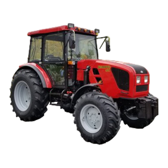
Outside appearance of BELARUS-921.6 tractor in standard configuration is shown on Figure 1.1.1. Outside appearance of BELARUS-921.6 tractor complete with FMD (front mounted device) is shown on Figure 1.1.2. Figure 1.1.1 – BELARUS-921.6 tractor Figure 1.1.2 – BELARUS-921.6 tractor complete with FMD (the rest is shown on Figure 1.1.1) -
Page 11: Specifications
921.6-0000010 OM 1.2 Specifications BELARUS-921.6 tractor main parameters and specifications are set forth in Table 1.2.1. Table 1.2.1 Parameter or Parameter value for property name BELARUS-921.6 tractor 1 Drawbar category according to GOST 27021: 2 Rated drawbar power, kN: 3 Engine a) model: D-245.5S4... - Page 12 921.6-0000010 OM Table 1.2.1 (cont'd) Parameter or Parameter value for property name BELARUS-921.6 tractor 7 The tractor travel speed (calculated) at the engine crankshaft rated rotation speed, on standard tyres, km/h: a) forward motion: 1) lowest: 2) highest: 27.0 b) reverse motion:...
- Page 13 To be defined according to component parts. Note – The tractor's gear number and travel speed are given in Table 1.2.1 at the engine crankshaft rated rotation speed for the BELARUS-921.6 tractor with GB 14х4 in- stalled (standard configuration). The BELARUS-921.6 tractor's gear number and travel speed with GB 18x4 (optional configuration) and GB 7х6 (optional configuration) installed...
-
Page 14: Tractor Composition
921.6-0000010 OM 1.3 Tractor Composition Tractor framework - half-frames. The BELARUS-921.6 tractor undercarriage - driven front and rear wheels, with pneu- matic low-pressure tyres. The steerable front wheels. The tractor is equipped with the four-stroke piston-type four-cylinder internal com- bustion engine with cylinders in-line vertical positioning, with diesel fuel direct injection and ignition by compression. - Page 15 Brakes: service – two-disc, dry-friction, on driving gears shafts of final drives. The service brakes control drive - hydrostatic. Parking brake – by service brakes with inde- pendent manual control. Brake drive of the BELARUS-921.6 tractor-trailer- two-line pneu- matic, interlocked with the tractor brake controls.
-
Page 16: Vibration Level At The Belarus-921.6 Tractor Operator's Workplace
921.6-0000010 OM 1.4 Vibration Level at the BELARUS-921.6 Tractor Operator's Workplace Vibration level at the operator's seat corresponds to the requirements of Council Di- rective 78/764/EEC. Vibration level values are stated in the EC type approval for each type of the seat. - Page 17 921.6-0000010 OM End of Table 1.6.1 Serial number Gear box number (as seen from the left of the tractor's movement direction) GB version number Clutch housing Gear unit Transmission and rear axle serial number (as seen from the right of the tractor's...
-
Page 18: Controls And Instrumentation
921.6-0000010 OM 2 Controls and Instrumentation 2.1 Location of the Tractor's Controls and Instrumentation Controls and instrumentation, which are installed inside of the tractor cab, are shown in Figures 2.1.1 and 2.1.2. 1 – sun visor; 2 – radio set installation place; 3 – recirculation flaps; 4 – overhead panel key switch unit;... - Page 19 921.6-0000010 OM 1 – control handle of the rear axle differential locking; 2 – parking brake lever; 3 – PTO shaft switching handle (independent/synchronous); 4 – PTO shaft control lever; 5 – GB gears and ranges switching lever; 6 – FDA drive control handle; 7, 8 – RMD hydraulic hoist control levers;...
-
Page 20: Instruments Panel Switches
921.6-0000010 OM 2.2 Instruments Panel Switches Switches of the instruments panel are shown in Figure 2.2.1. 1 – AB remote switch; 2 – steering column multifunction switch, left; 3 – starter and instruments switch; 4 – emergency brake light switch; 5 – steering column multifunction switch, right;... - Page 21 921.6-0000010 OM When the lever is pulled as far as it will go (position e, Figure 2.2.3) from position of the low beam, the high beam will be temporary activated (high beam flashing) regardless of the main light switch 6 (Figure 2.2.1) position.
- Page 22 921.6-0000010 OM Right steering column multifunction switch 5 (Figure 2.2.1) provides for activation of the front windshield two-speed wiper and washer. The front windshield wiper will be activated when the lever of the steering column switch 5 (Figure 2.2.1) is moved from ON position (position 0 according to Figure 2.2.5) into position a (first speed) or b (second speed).
-
Page 23: Overhead Panel Key Switch Unit And Rear Windshield Wiper Switch
921.6-0000010 OM 2.3 Overhead Panel Key Switch Unit and Rear Windshield Wiper Switch 1 – flashing beacon switch; 2 – cab fan switch; 3 – front working lights switch; 4 – rear work- ing lights switch (internal); 5 – rear working lights switch (external); 6 – rear windshield wiper and washer switch;... -
Page 24: Cab Heater-Fan Operation
921.6-0000010 OM 2.4 Cab Heater-fan Operation The cab heater-fan controls are shown in Figure 2.4.1. The tank for SCR system fluid (view from below) 1 – deflectors, 2 – control handle of the cab heater valve; 3 – hose ; 4 – hose clamp; 5 –... - Page 25 921.6-0000010 OM Only the dealer is allowed to drain the cooling fluid from the heating system, since during the cooling fluid draining process it is necessary to dismount/mount some elements of the SCR system. ATTENTION: WHEN THE HEATER-FAN OPERATES IN THE HEATING MODE, THE CAB IS SIMULTANEOUSLY VENTILATED.
-
Page 26: Air-Conditioning Unit Control
921.6-0000010 OM 2.5 Air-conditioning Unit Control 2.5.1 Air-conditioning Unit Control in the Air-Conditioning Mode Switches 1 and 2 are installed on the air-conditioned control panel (Figure 2.5.1). 1 – airflow rate adjustment switch; 2 – air-conditioned switch and cooling capacity adjustment. -
Page 27: Cab Ventilation
921.6-0000010 OM - check and if necessary pour the cooling fluid into the expansion tank up to upper edge of the expansion tank fastening clamp; - use the switch 1 (Figure 2.5.1) to turn the heater fan on, at that warm air shall be fed into the cab within one-five minutes, and this will confirm correct operation of the heat- ing system;... -
Page 28: Instruments Cluster
921.6-0000010 OM 2.6 Instruments Cluster The instruments cluster 13 (Figure 2.1.1) consists of the five indicators with five warning lights as shown in Figure 2.6.1. Version 2 Version 1 1 – tank reserve fuel level warning light; 2 – pneumatic system air pressure indicator; 3 –... - Page 29 921.6-0000010 OM ATTENTION: IF THE VOLTAGE INDICATOR DISPLAYS AN ABSENCE OF THE AB CHARGING, CHECK THE GENERATOR DRIVE BELT CONDITION AND TIGHTEN- ING! 2.6.3 The tank fuel level indicator scale 4 (Figure 2.6.1) has divisions 0–1/4–1/2– 3/4–1 (version 1) or 0–0.5–1 (version 2). The warning light 1 (orange) is built into the indi- cator scale and it lights up when the tank fuel level drops to 1/8 of the tank total volume.
-
Page 30: Indicator Light Unit
The glow plugs (GP), which are installed in the cylinder head, are used as the start- ing aid on the BELARUS-921.6 tractor. The glow-plugs controller might be installed for in- dividual control of the glow-plugs operation modes and their operation indicating. - Page 31 921.6-0000010 OM The glow plugs will not be activated, if the engine temperature is above plus 5 С. Meanwhile the GP indicator light 3 (Figure 2.7.1) will temporary light up for two seconds or will not light up at all.
-
Page 32: Multifunction Display And Mf Control Panel
921.6-0000010 OM 2.8 Multifunction Display and MF Control Panel 2.8.1 General The multifunction display 15 (Figure 2.1.1)(hereinafter referred to as MFD) and the multi- function display programming panel 19 (Figure 2.1.1) (hereinafter referred to as CP) display in- formation concerning the tractor systems and units operational parameters and provide an oper- ator with data on any system malfunction or failure. -
Page 33: Principle Of The Multifunction Display Operation And Purpose Of Its Indicators
921.6-0000010 OM The control panel 19 (Figure 2.1.1) can be used to manually program the indicator by the Parameter and Value buttons (see Figure 2.8.2). The Mode button can be used to change the parameters display mode, which are output on the parameters multifunction in- dicator (MFI). - Page 34 921.6-0000010 OM Table 2.8.1 Mode 540 Mode 1000 Upper (according to Figure 2.8.1) operating segment of the RPTO shaft RPM 1150 1050 2.8.2.4 The multifunction indicator (MFI) 17 (Figure2.8.1) is the liquid-crystal display, which simultaneously displays information in two fields 1 and 2 (Figure 2.8.3): 1 –...
- Page 35 921.6-0000010 OM Table 2.8.2 – Examples of the tractor operation parameters displaying on MFI Parameter Example of the parame- Parameter description displaying on MFI The counter accumulates information about The engine total the engine apparent operating time and saves apparent operating it when power supply is cut off.
-
Page 36: The Indicator Lights Of The Multifunction Display
921.6-0000010 OM Each malfunction message (Example: 0----, FUEL, C-BUS) will be displayed on the LCD according to their priority order irrelevant of the currently displayed information. If the Mode button is pressed sequentially, the messages will be switched one after another. - Page 37 921.6-0000010 OM MODE VALUE PARAMETER Figure 2.8.4 –Multifunction display programming panel 2.8.5.2 The Multifunction Display Programming Method When the parameter fixed value is selected, the MFD shall be programmed accord- ing to following method: - when the Parameter button (Figure 2.8.4) is pressed for the first time, the LCD will switch to the mode of programmable parameter designation and its numerical value view- ing.
- Page 38 660. When other tyre types are installed, it is necessary to set the parameter R value, which corresponds to the installed tyres' rolling radius. The BELARUS-921.6 tractor is not equipped with the PTO shaft RPM sensor; therefore, it is necessary to input value 0 here.
-
Page 39: Data Display Monitor And The Engine Control Panel
921.6-0000010 OM 2.9 Data Display Monitor and the Engine Control Panel 2.9.1 General The data display monitor 4 (Figure 2.9.2) is intended for displaying the actual pa- rameters of the engine operation, indication of the engine electronic control system (EECS) malfunctions and for the SCR parameters displaying. - Page 40 921.6-0000010 OM The monitor buttons 1, 2, 3, 4, 5 (Figure 2.9.1) are multifunctional. If any of the buttons 2, 3, 4 are pressed during the monitor operation, the display will show an image of the button bar 6, whose icons represent the current functions of each button. The main three sections representation will be recalled to the display if the button 1 is pressed.
- Page 41 921.6-0000010 OM Table 2.9.1 – The list of the engine operation parameters graphical and four-section indication Item Four sections Graphical Parameters Symbol number presentation presentation Voltage immediately on the terminals for the data display monitor connection, V Voltage on the AB terminals, which is measured by the engine electronic ...
-
Page 42: Engine Control System Panel
921.6-0000010 OM 2.9.4 Engine Control System Panel The engine control system panel 5 (Figure 2.9.2) includes the push-button switch for the diagnosis activation 1, the malfunctions diagnosis indicator 2, the socket for auxilia- ry equipment 3, the data display monitor 4, the socket for connection of the hitched ma- chines 6 (12V/25A), the diagnostic outlet 7. -
Page 43: Steering Control
2.10 Steering Control 2.10.1 General The BELARUS-921.6 tractor is equipped with the hydrostatic power steering (HPS), which is intended for the guiding wheels turning control and to decrease force required at the steering wheel, when the feed pump operates. If the engine is stopped, the HPS feed-... -
Page 44: Parking Brake Control
921.6-0000010 OM 2.11 Parking Brake Control Upper position of the lever 1 (Figure 2.11.1) – the parking brake is activated. Lower position of the lever 1 – the parking brake is deactivated. To deactivate the parking brake, press the button 2 on the control lever and lower the lever 1 down as far as it will go. -
Page 45: Gear Changing
2.15 Gear Changing 2.15.1 General The BELARUS-921.6 tractor in standard configuration is equipped with the synchro- mesh fixed-ratio two-range GB with one range and gear changing lever (for the operator's right hand) and with synchromesh reduction gearbox (GB 14F+4R). The tractor can be optionally equipped by the transmission with following component units: - synchromesh GB and synchromesh increasing gearbox (GB 14F+4R);... - Page 46 Figure 2.15.2 The gears diagram for the BELARUS-921.6 tractor on rear tyres 420/70R24, which is equipped with the synchromesh GB with synchromesh decreasing gear- Figure 2.15.3 The gears diagram for the BELARUS-921.6 tractor on rear tyres 14.9R30, which is equipped with the synchromesh GB with synchromesh decreasing gearbox...
-
Page 47: Gear Changing In The Transmission With The Synchromesh Gb And Synchromesh Increasing Gearbox
921.6-0000010 OM ATTENTION:FOURTH GEAR OF THE GB CAN BE ACTIVATED ONLY WHEN THE GB II RANGE IS ACTIVATED! ATTENTION: CHANGE THE GB GEARS AND RANGES ONLY WHEN THE TRAC- TOR IS STOPPED AND THE CLUTCH PEDAL IS FULLY PRESSED DOWN! WHILE... - Page 48 921.6-0000010 OM The BELARUS-921.6 tractor gears diagram plate, which is equipped with the synchro- mesh GB with synchromesh increasing gearbox, is installed on the cab's right windshield and shown in Figures 2.15.2 or 2.15.6 . Figure 2.15.2 The gears diagram for the BELARUS-921.6 tractor on rear tyres...
-
Page 49: Gear Changing In The Transmission With The Synchromesh Gb And Reverse Gear
921.6-0000010 OM ATTENTION:FOURTH GEAR OF THE GB CAN BE ACTIVATED ONLY WHEN THE GB II RANGE IS ACTIVATED! ATTENTION: CHANGE THE GB GEARS AND RANGES ONLY WHEN THE TRAC- TOR IS STOPPED AND THE CLUTCH PEDAL IS FULLY PRESSED DOWN! WHILE... - Page 50 921.6-0000010 OM The BELARUS-921.6 tractor gears diagram plate, which is equipped with the syn- chromesh GB with reverse gear, is installed on the cab's right windshield and shown in Figures 2.15.8 or 2.15.9. Figure 2.15.8 The gears diagram for the BELARUS-921.6 tractor on rear tyres 420/70R24, which is equipped with the synchromesh GB with reverse gear Figure 2.15.9 The gears diagram for the BELARUS-921.6 tractor on rear tyres...
-
Page 51: Gear Changing In The Transmission With The Mechanical Gb And Mechanical Reduction Gearbox
(not fixed middle position) position in order to make the engine starting easier at low tempera- tures. The BELARUS-921.6 tractor gears diagram plate, which is equipped with the mechanical GB with mechanical gearbox, is installed on the cab's right windshield and shown in Figures... - Page 52 Figure 2.15.11 The gears diagram for the BELARUS-921.6 tractor on rear tyres 420/70R24, which is equipped with the mechanical GB with mechanical decreasing gearbox Figure 2.15.12 The gears diagram for the BELARUS-921.6 tractor on rear tyres 14.9R30, which is equipped with the mechanical GB with mechanical decreasing gearbox...
-
Page 53: Front Driving Axle Drive Control
921.6-0000010 OM ATTENTION: CHANGE THE GB GEARS AND RANGES ONLY WHEN THE TRAC- TOR IS STOPPED AND THE CLUTCH IS DISENGAGED! ATTENTION: CHANGE THE STAGES OF THE MECHANICAL REDUCING GEAR- BOX ON ANY GB GEAR ONLY WHEN THE TRACTOR IS COMPLETELLY STOPPED AND WITH FULY DEPRESSED CLUTCH COUPLING PEDAL! 2.16 Front Driving Axle Drive Control... -
Page 54: Rear Power Take-Off Shaft Control
921.6-0000010 OM 2.17 Rear Power Take-off Shaft Control 2.17.1 The handle for the rear PTO shaft switching from independent to syn- chronous drive When the handle 3 (Figure 2.1.2)is moved into the lowermost position, the synchro- nous drive is activated; into uppermost – independent; middle position – neutral. -
Page 55: The Tractor Operation Without The Use Of The Rear Pto Shaft
921.6-0000010 OM To select required PTO shaft rotation speed, unscrew the bolt 1 by one revolution, rotate the arm 2 into position I or II and tighten the bolt 1. ATTENTION: CHANGE THE PTO SHAFT SPEEDS ONLY WHEN THE ENGINE IS OFF! 1 –... -
Page 56: Controlling The Rear Mounted Device
921.6-0000010 OM 2.18 Controlling the Rear Mounted Device 2.18.1 Controls of the RMD With Hydraulic Hoist The RMD is controlled by two handles 1 and 2 (Figure 2.18.1), which are installed in the cab in its side control panel 3. - Page 57 921.6-0000010 OM The draft control is the ideal mode for operation with the mounted and semi- mounted implements with tillage tools penetrating the soil. The system is responsive to the traction force changes (caused by the soil drag or the soil handling depth changes) through the top link of the hitch device mechanism.
-
Page 58: Controlling The Hms Pump
921.6-0000010 OM 2.19 Controlling the HMS Pump The HMS pump activation roller 5 (Figure 2.19.1) has two positions: - "HMS pump is ON" – roller 5 is rotated clockwise up to the stop; - "HMS pump is OFF" – roller 5 is rotated counter-clockwise up to the stop;... -
Page 59: Controlling The Front Mounted Device
Figure 2.20.2 – The diagram of the distributor outputs location and connection 2.21 Controlling the Front Mounted Device The BELARUS-921.6 tractor can be optionally equipped with the front mounted de- vice. Front mounted device will be installed only if the tractor is equipped with the front tyres 12.4L-16 and rear tyres 14.9R30. -
Page 60: Electric Fuses And Electromagnetic Relays
921.6-0000010 OM 2.22 Electric Fuses and Electromagnetic Relays 2.22.1 General The electric fuses are intended for protection from the electric circuits’ overloads and short-circuits. WARNING: TO PREVENT THE TRACTOR ELECTRIC WIRING BURNING, NEV- ER USE FUSES WITH RATED CURRENT INTENSITY HIGHER THAN STATED IN THIS SECTION. - Page 61 921.6-0000010 OM a) BKA-7.3722-02 b) BK-1-02 1 – electric fuse; 2 – red indicating LED; 3 – green indicating LED; 4 – electromagnetic re- lay; 5 – set of spare fuses. Figure 2.22.2 – The switching unit The diagram of fuses and relays location in SU is shown in Figure 2.22.3.
- Page 62 921.6-0000010 OM The relay and fuses purpose tables, which are shown in Figure2.22.3, are glued from inside to the upper plastic cover 2 (Figure 2.22.1) from the front windshield side. Information on the relays and fuses purpose and fuses rated values are given in Tables 2.22.1 and 2.22.2.
- Page 63 921.6-0000010 OM Table 2.22.2 – Purpose of the relays Designation Purpose of the relay of the relay К1 Ratio set (car radio) К2 Rear working lights (pair of internal lights) К3 Air-conditioner or heater К4 Rear working lights (pair of external lights) К5...
- Page 64 In addition to the fuses, which are located in the switching unit and shown in Fig- ure2.22.3, the BELARUS-921.6 tractor network is equipped with fuses for the electric equipment power supply circuits. These fuses are located in following areas of the engine compartment: - in area of the coarse fuel filter;...
- Page 65 921.6-0000010 OM The fuses in area of the coarse fuel filter are shown in Figure 2.22.7. 1 –fuse for power supply of the starter relay (located in the switching unit) and AB remote activation/deactivation circuit, rating 80 А; 3, 4 – fuses for power supply of the switching unit, rating 60 А;...
-
Page 66: Fuses Of The Engine Electronic Control System
921.6-0000010 OM 2.22.3 Fuses of the Engine Electronic Control System Three EE (electric equipment) fuses and two EECS fuses are installed in the fuses unit 2 (Figure 2.22.9). The fuses unit 2 (Figure 2.22.9) is located above the AB 1. To gain access to the fuses unit 2, lift the tractor bonnet. - Page 67 921.6-0000010 OM The EECS fuses, which are located in the fuses unit 4 (Figure2.22.10), are shown in Figure 2.22.11. 1 – power supply fuse (after instruments activation) for diagnostic equipment, rating 7.5 А; 2 – power supply fuse (after instruments activation) for the monitor, electronic ECU and SCR , rating 7.5 А;...
-
Page 68: Cab Locks And Handles
921.6-0000010 OM 2.23 Cab Locks and Handles 2.23.1 Cab Doors Locks The tractor cab left and right doors are lockable from inside by the locks 4 (Figure 2.23.1). The lever 5 is intended for opening the cab left and right doors from inside. The door lock opens when the lever 5 is moved backwards. -
Page 69: Opening The Rear Windshield
921.6-0000010 OM 2.23.3 Opening the Rear Windshield To open the rear windshield, rotate the handle 1 (Figure 2.23.3) to the left (in refer- ence to the tractor movement direction), then hold the handrail 2 and push the rear wind- shield 3 until it fixes in opened position. -
Page 70: Seat And Its Adjustment
921.6-0000010 OM 2.24 Seat and its Adjustment 2.24.1 General The seat is equipped with mechanical suspension, which consists of the laminated torsion bar and double-action shock-suspension. The "scissor' type guiding mechanism provides for the seat straight vertical movement. The seat ride travel is 90 mm. -
Page 71: Controlling The Pneumatic System Compressor
921.6-0000010 OM 2.25 Controlling the Pneumatic System Compressor The pneumatic system compressor activation handle 1 (Figure 2.25.1) has two posi- tions: - left (arrow on handle points forward in reference to the tractor movement direction) – "compressor is OFF"; - right (arrow on handle points backwards in reference to the tractor movement di- rection) –... -
Page 72: Connecting The Hitched Machines Additional Electric Equipment
921.6-0000010 OM 2.26.2 Connecting the Hitched Machines Additional Electric Equipment To control the hitched machines operation process, it is allowable to equip the trac- tor cab with monitoring equipment (control panels), which is the hitched machine accesso- The hitched machines are equipped with various electric and electronic units, op- eration of which can have an effect on the tractor instruments readings. -
Page 73: Connecting The Hitched Machines Electric Equipment Through Additional Sockets
In addition to the socket for the hitched agricultural equipment connection, the BELA- RUS-921.6 tractor is also equipped with additional electrical sockets. Location of these sock- ets is shown in Figure 2.9.1. Power to sockets 3 and 6 (Figure 2.9.2) is supplied after the AB (earth) is ON. -
Page 74: Scr System Operation Indication
921.6-0000010 OM Prior to filling the tank 1 (Figure 2.27.1) by AdBlue reagent, it is necessary to clean the tank 1 filling neck 2 from dust and dirt. ATTENTION: IF THE ENVIRONMENT TEMPERATURE IS BELOW MINUS 11 °С, THE TANK FOR SCR SYSTEM FLUID SHALL BE FILLED BY AdBlue REAGENT ONLY TO 80% OF THE TANK FILLING VOLUME. - Page 75 921.6-0000010 OM 1 – button for returning into the engine parameters displaying mode; 2 – button for turn- ing the pages with the SCR system parameters; 3 – button for recalling the engine parameters graphical representation; 4 – button for recalling the errors list (malfunctions); 5 – pop-up panel reset button;...
- Page 76 921.6-0000010 OM Remaining time to hard limit- Malfunction code ing of torque (50%) Remaining time to light limiting Current status of torque (25%) Figure 2.27.6 – The fourth page of SCR parameters If there are errors (malfunctions) in the SCR system, the timers will be activated, which countdown time until the engine torque will be limited (light limiting 25% and hard limiting 50%).
- Page 77 921.6-0000010 OM If the AdBlue reagent level has fallen below 28% of the tank filling volume simultaneously with the engine operation errors, which are not related to the SCR operation, the monitor will show blinking symbols as in Figure 2.27.9.
-
Page 78: Proper Usage Of The Tractor
921.6-0000010 OM 3 Proper Usage of the Tractor 3.1 Safety Measures While Preparing the Tractor for Operation Strict observance of safety requirements will provide for the tractor safe operation will increase its reliability and longevity. Persons no younger than 17 years are allowed to operate the tractor (age can vary depending on your country legislation), who received the driver's licence for operation of the tractor of drawbar category 1.4 and who received training for occupational safety and... -
Page 79: Tractor Usage
921.6-0000010 OM 3.2 Tractor Usage 3.2.1 Entering the Tractor Enter the tractor through the cab left door. The footboard is installed for entering convenience. 3.2.2 Engine Preparation and Starting To start the engine, proceed as follows: - apply the tractor parking brake;... - Page 80 921.6-0000010 OM 4) Following lights will be activated on the indicator light unit: the indicator light of the emergency oil pressure drop in the HPS. The engine lubrication system emergency oil pressure warning lamp (and buzzer will sound), the pneumatic system emergency air pressure warning lamp (if pressure is below allowable level), tank reserve fuel level warn- inglight (if fuel in the tank is on reserve level).
-
Page 81: Starting The Tractor Movement, Switching The Gb
ING AND MALFUNCTION! Prior to the movement start, determine required speed of the tractor movement. The BELARUS-921.6 tractor speeds diagram is shown in the instruction plate on the right windshield of the cab and in subsection2.15 "Gears changing". To start the tractor movement, proceed as follows: - decrease the engine RPM;... - Page 82 921.6-0000010 OM ATTENTION: CHANGE THE GB GEARS AND RANGES ONLY WHEN THE TRACTOR IS STOPPED AND THE CLUTCH IS DISENGAGED! IN CASE OF THE TRACTORS WITH SYNCHROMESH GB, WHILE TRANSPORTATION WORKS PERFORMING IT IS ALLOWA- BLE TO CHANGE GEARS WHILE MOVING FROM THE SECOND TO THE THIRD AND...
-
Page 83: Stopping The Tractor
921.6-0000010 OM 3.2.4 Stopping the Tractor To stop the tractor, proceed as follows: - decrease the engine RPM; - press the clutch pedal as far as it will go; - place the GB ranges and gears switching lever into neutral position;... -
Page 84: Pto Shaft Usage
VOM 1с-571 RPM; VOM 1-571 RPM; VOM 2-955 RPM. Power, which is transmitted by shanks 1с/1/2 from the rear PTO shaft, and maxi- mum allowable moment for the PTO shaft shanks 1с/1/2 of the BELARUS-921.6 tractors are specified in Table 3.2.2. - Page 85 921.6-0000010 OM Table 3.2.2 Power transmitted by the Maximum allowable mo- PTO shaft shank, kW, no ment at the PTO shaft PTO shaft shank type more than shank, N·m VOM 1C 59.4 1050 VOM 1 59.4 1050 VOM 2 59.4 TO work with the rear PTO shaft, remove the protective cap 1 (Figure 3.2.1), which co-...
-
Page 86: Selecting The Optimal Inner Pressure In Tyres Depending On Operation Conditions And Load On The Tractor Axis, Tyres Operation Rules
921.6-0000010 OM 3.2.8 Selecting the Optimal Inner Pressure in Tyres Depending on Operation Conditions and Load on the Tractor Axis, Tyres Operation Rules 3.2.8.1 Selecting the optimal inner pressure in tyres depending on operation condi- tions and load on the tractor axis... - Page 87 (it is allowed to use other tyre inflation pressure inspec- tion instruments with metrological performance similar to the pressure gage MD-214). Table 3.2.3 – Nominal loads on the single tyres of the BELARUS-921.6 tractor for selection of the operational modes under various speeds and tyre inner pressures...
- Page 88 921.6-0000010 OM - do not allow the tractor operation with tyres inner pressure, which does not corre- spond to established nominal values for each specific usage case; - maintain established rated values of the tyres inner pressures according to direc- tions in this manual;...
- Page 89 921.6-0000010 OM 1 – pressure regulator; 2 – wing-nut; 3 – pneumatic system cylinder. Figure 3.2.2 – Tyres inflating ATTENTION: WHEN THE PRESSURE IN CYLINDER INCREASES UP TO 0.77 MPa, THE PRESSURE REGULATOR WILL SWITCH THE COMPRESSOR TO THE IDLE RUN MODE AND TYRES INFLATION WILL STOP AUTOMATICALLY.
-
Page 90: Formation Of The Rear Wheels Spacing
921.6-0000010 OM 3.2.9 Formation of the Rear Wheels Spacing If basic set tyres 420/70R24 are installed, change the rear wheels spacing by mov- ing the hub with wheel on the half-axle, interchanging wheels from one side to another and by changing position of the wheel disk in relation to the rim. Installation diagrams and wheels spacing dimensions for tyres 420/70R24 (basic set) are shown in Table 3.2.4... - Page 91 921.6-0000010 OM End of Table 3.2.4 Mounting di- mension from Versions of the disk and rim Wheels Disk offset the hub end Mounting method installation spacing K, X, mm face to the half- description axle end face H, mm The disk is mating...
- Page 92 921.6-0000010 OM - to provide for wheels spacing by interchanging wheels from one side to another with- out changing the disk position in relation to the rim, remove wheels and interchange them from one side to another; - provide for wheels spacing by changing the disk position in relation to the rim on...
- Page 93 921.6-0000010 OM ATTENTION: THE REAR WHEELS IN THE CONDITION AS DELIVERED FROM THE WORKS ARE SET FOR THE WHEELS SPACING ACCORDING TO DIAGRAM 1 (FIGURE 3.2.5)! To change the rear wheels spacing, proceed as follows: - park the tractor on the level site, place wheel chokes under front and rear wheels, clean half-axles from dirt;...
-
Page 94: Formation Of The Front Wheels Spacing
921.6-0000010 OM 3.2.10 Formation of the Front Wheels Spacing Change the front wheels spacing by interchanging wheels from one side to another. The front wheels spacing can have following values in mm: 1270, 1420 (for tyres 265/70R16), and 1250, 1400 (for tyres 12.4L-16). -
Page 95: Safety Measures During The Tractor Operation
921.6-0000010 OM 3.3 Safety Measures during the Tractor Operation 3.3.1 General Safety Measures during the Tractor Operation Do not operate the tractor in confined areas without required ventilation. Exhaust gases can lead to death. The tractor starting and operation with opened side panels is prohibited. - Page 96 921.6-0000010 OM Trailers, semi-trailers and agricultural machines (equipped with the brake system), which are hitched to the tractor, shall be equipped with the brake system, which provides for following: - machine braking while moving; - brake application when the machine is disconnected from the tractor;...
- Page 97 921.6-0000010 OM Prevent operation of the tractor with malfunctioned instrumentation. It is prohibited to inflate tyres without pressure control. While hitching the tractor to the agricultural machines additionally observe the safe- ty requirements for these machines operation. Prior to coupling the tractor to the agricultural machines, make sure that RMD lower and upper arms automatic grippers are clean and in good working order.
-
Page 98: Fire Safety Measures
921.6-0000010 OM 3.3.2 Fire Safety Measures The tractor shall be provided with fire-fighting equipment: shovel and powder fire ex- tinguisher (to be provided by the customer). IT IS PROHIBITED TO OPERATE THE TRACTOR WITHOUT FIRE-FIGHTING EQIUPMENT. Fill the tractor with fuel and lubricants by mechanised method with the engine stopped. - Page 99 921.6-0000010 OM While hay, straws collection or working in areas with increased fire danger do not allow build-up of inflammable materials on the silencer guards or connecting gas lines. During daily maintenance, it is mandatory to perform following operations: - visually inspect condition of the electric wiring, wire harnesses in the engine com- partment, in the cab front wall area and visible parts for signs of rubbing, melting or exter- nal insulation damage.
-
Page 100: The Tractor Final Assembly And Running In
921.6-0000010 OM 3.4 The Tractor Final Assembly and Running In 3.4.1 The Tractor Final Assembly The BELARUS-921.6 tractor is delivered to the customer assembled and final as- sembly is not required. 3.4.2 Maintenance Prior the Tractor Running In Prior to putting the new tractor into operation perform following actions: - wash the tractor, remove preservation lubricant (if there is any on the tractor). -
Page 101: Maintenance During The Tractor Running In
921.6-0000010 OM Start the engine. Let the engine run at idle speed for five minutes and gradually in- crease rotation speed up to 1600 RPM, then perform running in under load for 30 hours of the tractor operation. While performing the 30-hours running in, comply with following instructions: - constantly monitor instruments readings, lubrication, cooling and power supply systems operation. -
Page 102: Actions In Emergency Situations
921.6-0000010 OM - check and if necessary adjust the clutch control, service and parking brakes control, pneumatic system brake valve actuator; - replace oil in the transmission; - replace oil in the engine case; - replace the engine oil filter;... -
Page 103: Hitching
Areas of allowable BELARUS-921.6 tractor usage – areas with unrestricted air ex- change, sufficient bearing capability and passability for the tractor overall dimensions. Types of works to be performed by the BELARUS-921.6 tractor - horticultural crops and grapes cultivation and harvesting, as well as various agricultural operations with mounted, semi-mounted and trailed machines and implements for transport and livestock production op- erations. -
Page 104: Types Of Agricultural Machines To Be Hitched To The Tractor
Person operating the tractor is personally responsible for observing the road traffic rules and safety rules, as well as safety measures and correct usage of the BELARUS- 921.6 tractor, which are set forth in this operation manual. Qualification of the service personnel who works with the BELARUS-921.6 tractor:... -
Page 105: Mounted Devices
921.6-0000010 OM - semi-trailer– usually connected to single point by the hitch ring to TH. It is possible to use two-point joint connection to MD (upper link is not used). The tractor partially bears weight of the machine in transportation position and most of the weight is supported by own travelling wheels (usually at least two). - Page 106 RMD diagram. Diagram of the rear mounted device of NU-2 design for the BELARUS-921.6 tractor is shown in Figure 4.3.1. To provide for required position of the machines following RMD adjustments in ver- tical and horizontal planes using the upper link and braces are available: 1.
- Page 107 921.6-0000010 OM PTO shaft area Figure 4.3.1 – Diagram of the rear mounted device of NU-2 design Table 4.3.1 – Main parameters and connecting dimensions of the RMD Typical size (design) NU-2 of the device (Figure 4.3.1) Category 1 (according to ISO...
-
Page 108: Rmd Elements Adjustment Rules
921.6-0000010 OM 4.3.3 RMD Elements Adjustment Rules 4.3.3.1 Brace The BELARUS-921.6 tractor is equipped with two screw braces. 1 –screw with joint; 2 – lock nut; 3 –drawbar; 4 –screw with joint. Figure 4.3.2 – Screw brace To adjust the screw brake length, proceed as follows: - unscrew lock nuts 2 (Figure 4.3.2);... - Page 109 921.6-0000010 OM 4.3.3.3 Telescopic drawbars Telescopic drawbars are intended for limiting the lateral sway of the mounted device lower links in transportation and working positions. Theyprovide for locking of the lower links (of the implement) or swaying within ± 55 mm.
- Page 110 921.6-0000010 OM 4.3.3.4 Stabilizer The lower links stabilizer is installed instead of the crossbar and provides for stand- ard dimension between grippers and for locking of the lower links (of the implement) or the RMD rocking within ± 55 mm.
- Page 111 921.6-0000010 OM - fasten plate 12, spacers 15 on lower links ends 14 using bolts 16, then screw nuts with washers and tighten them by torque from 320 to 360 N·m; - install the cotter pins 4 (Figure 4.3.4) of drawbars into openings ("drawbar is un- locked") to mount the RMD with cross-bar or screwbolts 6 (Figure 4.3.5) installed in...
- Page 112 921.6-0000010 OM -slowly lift the implement and check for clearances between the tractor and imple- ment in lifted position; -check for presence of required side swaying of the lower links and adjust if neces- sary by drawbars. WARNING: SOME MOUNTED OR SEMI-MOUNTED EQUIPMENT CAN TOUCH THE CAB AND DAMAGE IT.
-
Page 113: Front Three-Point Mounted Device
921.6-0000010 OM 4.3.5 Front Three-Point Mounted Device The BELARUS-921.6 tractor can be optionally equipped with the front mounted de- vice (FMD). The bracket 3 (Figure 4.3.8) of the front mounted device shall be installed onto front plane of spacer 2 using two pin bushings and ten bolts, and fastened by additional plates 1 to the side surface of the tractor half-frame. - Page 114 921.6-0000010 OM The FMD is intended for following purposes: - formation of combined units (cultivator in front and planter etc. behind); - transportation of single machines, which belong to the rear mounted combined units, while transporting over long distances. When the FMD is installed, the front ballast weights are not installed onto the trac- tor.
-
Page 115: Rules For Connecting The Agricultural Machines To Fmd
921.6-0000010 OM End of Table 4.3.2 7 Diameter of upper link joint pivot, mm 8 Diameter of lower links joint opening, mm 28.7 9 Column height , mm 10 Suspension axis length along shoulders 11 Device capacity, kN at 610 mm offset from the suspension axis __________________________________________________________________________________________________ Dimension is specified for the hitched machine. -
Page 116: Tow Hitches
4.4 Tow Hitches 4.4.1 General The tow hitches of the BELARUS-921.6 tractor might be completed with the hitching elements TSU-ZV (long tow fork), TSU-1Zh-01 (double cross-bar), which provide for hitching and transportation of the mounted and semi-mounted machines with connecting devices ac- cording to following requirements: - compatibility of connecting dimensions;... - Page 117 921.6-0000010 OM Table 4.4.1 – Main parameters and connecting dimensions of the TSU-ZV (long tow fork) Typical size (design) TSU-ZV (long tow fork) 1 Place of installation Rear lifting device, only lower position of the fork 2 Structural features Rotating...
-
Page 118: Tow Hitch Tsu-1Zh-01 (Double Cross-Bar)
921.6-0000010 OM 4.4.3 Tow hitch TSU-1Zh-01 (double cross-bar) Lower right link Lower left link Figure 4.4.2 – Diagram of TSU-1Zh-01 installation Table 4.4.2 – Main parameters and connecting dimensions of the TSU-1Zh-01 (dou- ble cross-bar) Typical size (design) TSU-1Zh-01 (double cross-bar) -
Page 119: Particularities Of The Tractor Hydraulic System Usage For Driving The Work Tools And Other Elements Of The Hitched Machines And Implements, Which Are Equipped With Hydraulic Systems
ATTENTION: SPECIFIC OIL FEED RATE IS NECESSATY TO GUARANTEE RE- QUIRED ROTATION SPEED OF THE HITCHED MACHINES HYDRAULIC MOTOR. OP- ERATING FLUID SUPPLY ON THE BELARUS-921.6 TRACTOR DEPENDS ON THE EN- GINE RPM, THEREFORE THE MACHINE HYDRAULIC DRIVE SHALL BE EQUIPPED... -
Page 120: Installing The Front Ballast Weights
2.20.2. 4.6 Installing the Front Ballast Weights The BELARUS-921.6 tractor without FMD can be equipped with the ballast weights 200 kg (10 pieces, 20 kg each). While working with heavy mounted machines and implements in order to maintain the tractor normal controllability under conditions of significant off-loading of the front axle it is necessary to install additional ballast weights 1 (Figure 4.6.1). -
Page 121: The Trailer Brakes Actuator
921.6-0000010 OM 4.7 The Trailer Brakes Actuator 4.7.1 General The BELARUS-921.6 tractor in basic configuration is equipped with the two-line pneu- matic actuator of the trailer brakes. Your tractor optionally can be equipped with single-line pneumatic actuator of the trailer brakes or with combined pneumatic actuator of the trailer brakes. -
Page 122: Two-Line Actuator Of The Trailer Brakes
921.6-0000010 OM 4.7.3 Two-line Actuator of the Trailer Brakes The two-line pneumatic actuator provides for the trailers and agricultural machines brakes control, which are equipped with the two-line pneumatic actuator of the brakes. The pneumatic actuator is also used for the tyres inflation and other purposes, where the com- pressed air energy is required. - Page 123 921.6-0000010 OM The pneumatic actuator is equipped with the valve-type coupling heads 11, 12, 13 (Figure 4.7.3). The coupling head valves prevent air escaping when the pneumatic actua- tor is used without the trailer (for example during tyres inflation) and in case of emergency trailer decoupling.
-
Page 124: Determination Of The Capabilities To Use Pto Shaft And Cardan Shafts
THAN THE ALLOWABLE TORQUE OF THE TRACTOR PTO SHAFT SHANK, THEN IT IS PROHIBITED TO HITCH SUCH MACHINE TO THE TRACTOR! Note – Maximum allowable torques on various types of the BELARUS-921.6 tractor PTO shaft shanks are specified in subsection 3.2.7 "PTO shaft usage". -
Page 125: Particularities Of The Pto Shaft And Cardan Shafts Usage
921.6-0000010 OM 4.9 Particularities of the PTO Shaft and Cardan Shafts Usage WARNING: BE CAREFUL WHEN THE PTO SHAFT OPERATES AND THE HITCHED MACHINE CARDAN SHAFT ROTATES. WHEN THERE ARE PEOPLE IN THE PTO SHAFT OPERATION AREA, THESE PEOPLE CAN BE DRAWN IN, SOME PARTS OF CLOTHING CAN BE CATCHED BY ROTATING PARTS OF THE CARDAN SHAFT AND OTHER MOVING PARTS OF THE MACHINE. - Page 126 8. When the cardan shaft is used for the first time, it is obligatory to check the cardan shaft length and if necessary adjust it according to the BELARUS-921.6 tractor operation con- ditions. For the most detailed recommendations concerning the cardan shaft see the technical documentation appended to the machine.
- Page 127 921.6-0000010 OM 10. When the tractor and hitched machine are located along straight line and when the cardan shaft is fully retracted, check for sufficient clearance L (Figure 4.9.4, detail В) between the pipe end face and the cardan joint fork end face. Minimum allowable clear- ance L shall be no less than 50 mm.
-
Page 128: Methods For Changing The Tractor Towing And Hitching Properties And Cross-Country Ability
- use the rear axle differential locking. Note – Nominal values for air pressure in the BELARUS-921.6 tractor front and rear tyres under available load and speed are described in subsection 3.2.8 " Selecting the opti- mal inner pressure in tyres depending on operation conditions and load on the tractor axis,... -
Page 129: Particularities Of The Tractor Usage Under Special Conditions
INCLUDING ON STEEP HILLS. THEREFORE, THE TRACTOR IS NOT EQUIPPED WITH SPECIAL DEVICES, FOR EXAMPLE WITH THE MAXIMUM INCLINATION ANNOUNCIA- TORS! ATTENTION: IT IS FORBIDDEN TO USE THE BELARUS-921.6 TRACTOR FOR GRASS (SILAGE OR HAYLAGE) COMPACTING IN TRENCHES AND PITS! 4.11.2 Usage of Reagents for Chemical Treatment The cab corresponds to requirements for category 2 according to EN 15695-1:2009. -
Page 130: Determining The Total Mass, Loads Onto Front And Rear Axis, Tyres Capacity And Required Minimum Ballast Weight
921.6-0000010 OM 4.12 Determining the Total Mass, Loads onto Front and Rear Axis, Tyres Ca- pacity and Required Minimum Ballast Weight Values of the loads onto the tractor axis, which is part of the MTA, can be deter- mined by immediate weighting on the scales for automotive mechanical means of suffi- cient capacity. -
Page 131: Possibility To Install The Front Loader
20% OF THE TRACTOR OPERATIONAL WEIGHT AND THE CONTROLLABILITY CRI- TERIA IS NO LESS THAN 0.2! 4.13 Possibility to Install the Front Loader ATTENTION: THE BELARUS-921.6 TRACTOR IS NOT INTENDED FOR INSTAL- LATION OF ANY MOUNTED EQUIPMENT, INCLUDING MOUNTED FRONT LOADERS (WHICH ARE NOT MOUNTED, SEMI-MOUNTED, TRAILER, SEMI-TRAILER MA-... -
Page 132: Maintenance
921.6-0000010 OM 5 Maintenance 5.1 General Maintenance (MT) is required for keeping the tractor in good working condition dur- ing operation. Non-observing of established periodicity and low quality of MT will greatly decrease the tractor service life, lead to increase in malfunctions number, the engine pow- er dropping and increase of the tractor operation expenses. - Page 133 921.6-0000010 OM Table 5.1.1 – Types of scheduled maintenance Type of maintenance Periodicity, h Maintenance during operational running in Prior to the tractor running in, MT during running in and after running in (after 30 hours of operation) Daily (DMT)
-
Page 134: Providing An Access To The Tractor Component Parts For Maintenance
921.6-0000010 OM 5.2 Providing an Access to the Tractor Component Parts for Maintenance Prior to maintenance it is necessary to remove both side members 9, 10 and to open the bonnet 3 (Figure 5.2.1). To open side members 9, 10, proceed as follows: - unscrew one bolt 7 and two bolts 8;... -
Page 135: Maintenance Procedure
921.6-0000010 OM 5.3 Maintenance Procedure Content of the BELARUS-921.6 tractor maintenance procedure during operation is specified in Table 5.3.1. Table 5.3.1 Periodicity, h Opera- Description of the operation tion No. 8-10 125 250 500 1000 2000 Check the oil level in the engine case... - Page 136 921.6-0000010 OM Table 5.3.1 (cont'd) Periodicity, h Opera- Description of the operation 8-10 125 250 500 1000 2000 tion No. Check the oil level in the FDA cardan drive in- termediate support Х Check / adjust the clutch control Х...
- Page 137 921.6-0000010 OM End of Table 5.3.1 Periodicity, h Opera- Description of the operation 8-10 125 250 500 1000 2000 tion Replace the brake fluid in the clutch control ac- tuator Replace the brake fluid in the service brake con- trol actuator...
-
Page 138: Scheduled Maintenance Operations
921.6-0000010 OM 5.4 Scheduled Maintenance Operations 5.4.1 Daily Maintenance (DMT) After Each 8 - 10 Hours of Operation or Daily 5.4.1.1 General directions Perform following operations every 8 - 10 hours of the tractor operation or when the tractor shift ends (whichever is earlier): 5.4.1.2 Operation 1. - Page 139 921.6-0000010 OM 5.4.1.4 Operation 3. Checking the cooling fluid level in the engine cooling system. The fooling fluid level in the engine cooling system shall be monitored according to the expansion tank filling level 9 (Figure 5.4.3). CF quantity in the expansion tank shall be at the level 20…30 mm from the expansion tank bottom to the upper edge of clamp 11,...
- Page 140 921.6-0000010 OM 5.4.1.5 Operation 4. Checking the oil level in the HMS tank Park the tractor on flat site prior to checking the oil level. Lower the RMD links into low- ermost position then stop the engine and apply the tractor parking brake.
- Page 141 921.6-0000010 OM 5.4.1.7 Operation 6. Checking the AdBlue level in the SCR system fluid tank. Check AdBlue level in the SCR system fluid tank, refill if necessary. To check AdBlue level in the SCR system fluid tank, proceed as follows: - rotate the starter and instruments switch key from position0 (OFF) into position I (In- struments are ON).
- Page 142 921.6-0000010 OM 5.4.1.12 Operation 11. Checking the air-conditioner hoses fastening. Note -This operation is to be performed when the tractor is equipped with the air- conditioner instead of the fan-heater. Visually inspect the air-conditioner hoses fastening. The binding clamps should reli- ably fasten the air-conditioner hoses.
- Page 143 921.6-0000010 OM 1 – bolt; 2 – panel of cab upper section; 3 – heater valve handle; 4 – cap. Figure 5.4.7 – Opening the upper section Disconnect the drainage tubes 1 (Figure 5.4.8) from the heater-cooler 2 outputs, blow off the tubes by compressed air and connect them again to the heater-cooler 3.
- Page 144 921.6-0000010 OM 5.4.1.14 Operation 13. Checking / cleaning the air-conditioner condenser Note -This operation is to be performed when the tractor is equipped with the air- conditioner instead of the fan-heater. Check the air-conditioner condenser core for cleanliness. If it is clogged, clean the condenser by compressed air.
- Page 145 921.6-0000010 OM 5.4.1.18 Operation 17. Checking the brakes operation while moving, the engine, steering control, illumination and alarming fixtures operability. Following tractor operation parameters shall be provided: - the engine shall operate steadily in all modes; - controls, visual and audible alarming devices shall be in good working order;...
- Page 146 921.6-0000010 OM 5.4.1.21 Operation 20. Draining the condensate from the engine CAC radiator tanks. During autumn-winter season this operation shall be performed each 8-10 hours of the tractor operation. During the spring-summer - each 125 hours of the tractor operation.
-
Page 147: Maintenance Each 125 Hours Of Operation
921.6-0000010 OM 5.4.2 Maintenance Each 125 Hours of Operation 5.4.2.1 General directions Perform previous operations and operations listed in this subsection 5.4.2. 5.4.2.2 Operation 21. Checking the tightening of the wheels threaded connections Checking the tightening of the wheels threaded connections is to be performed once during the first DMT (after 8-10 hours of operation), which is performed by the cus- tomer, then after every 125 hours of the tractor operation. - Page 148 5.4.2.6 Operation 25. Checking the condition of the engine cooling system fan driv- ing belt The BELARUS-921.6 tractor is equipped with the engine fan poly-V belt with auto- matic tensioner, which does not require tension checking and adjustment. It is necessary to check visually for damages only the belt.
- Page 149 921.6-0000010 OM 1 – water drain valve; 2 – water-collecting cage; 3 – filtering element; 4 – housing of the fuel coarse filter. Figure 5.4.14 – Fuel coarse filter ATTENTION: IF INFORMATION ABOUT WATER PRESENCE IN THE FUEL COARSE FILTER IS OUTPUT TO THE DATA DISPLAY MONITOR DURING THE TRAC-...
- Page 150 921.6-0000010 OM To clean the filter of the cab ventilation and heating system, proceed as follows: - to gain access to the filter, install support or small ladder; - unscrew two screws 2 (Figure 5.4.15) with plastic heads, which are located under the cab roof extending edge;...
- Page 151 921.6-0000010 OM If this requirement is not fulfilled, then it is necessary to adjust the belt tension in the air-conditioner compressor drive. 2. Adjusting the belt tension in the air-conditioner compressor drive: Adjust the belt 1 (Figure 5.4.16) tension by rotating the compressor 2 on the rota- tion axis A and threaded connection clamp B in sector groove C.
- Page 152 921.6-0000010 OM - screw the plunger 9 of the main cylinder 11 into fork 7 to provide for dimension B, then tighten the nut 8 with torque from 30 to 50 N·m; - while screwing-in and unscrewing the bolt 3 make sure, than the pedal 6 move- ment distance from the initial position until the plunger 9 contacts the piston 10 (measured at the pedal pad centre) will be equal to dimension C;...
- Page 153 921.6-0000010 OM When the hydraulic system is pumped and the engine is stopped, total operating travel of the pedal 6 (Figure 5.4.18) shall be equal to dimension E, which corresponds to the lever 27 movement by value F. 1 – tank; 2, 13 – spring; 3, 12 – bolt; 4, 8, 24 – nut; 5, 26 – pivot; 6 – pedal; 7, 25 – fork;...
-
Page 154: And Special Mt Performance Periods
921.6-0000010 OM 5.4.3 Maintenance after each 250 hours of operation (2MT-1), after each 500 hours of operation (MT-2), each 1000 hours of operation (MT-3), each 2000 hours of operation (special maintenance) and maintenance, which does not concur with MT-1, 2MT-1, MT-2, MT-3 and special MT performance periods 5.4.3.1 General directions... - Page 155 921.6-0000010 OM The reason for the steering wheel increased clearance can also be the loosened crown nuts of the HPS hydraulic cylinder cone pivots. 1 – crown nuts; 2 – steering link; 3 – cotter wire; 4 –plug; 5 - joint.
- Page 156 921.6-0000010 OM c) repeat operations described in subsections 3 and 4. d) if the value (A - B) is within range from 0 to 8 mm – use torque from 100 to 140 N·m to tighten the lock nuts 1 and 3 of the steering link while not changing its length.
- Page 157 921.6-0000010 OM 2. Check the pedals free travel. The pedals 8, 9 free travel shall be within range from 4 to 8 mm. If this requirement is not fulfilled, then adjust the pedals free travel accord- ing to following directions: - remove cotter pins from pivots 6 and disconnect forks 3 from pedals 8 and 9 rods;...
- Page 158 921.6-0000010 OM 1 – right service brake cylinder; 2 – lock nut; 3 – fork; 4 – pivot; 5 – lever of the right service brake; 6 – adjusting bolt-link; 7 – overflow valve; 8 – overflow valve; 9 – lever of the left service brake;...
- Page 159 921.6-0000010 OM 5.4.3.5 Operation 45. Checking / adjustment of the parking brake control ATTENTION: CHECK AND IF NECESSARY ADJUST THE PARKING BRAKE CON- TROL WHEN THE SERVICE BRAKE CONTROL ADJUSTMENT OPERATIONS AFE FIN- ISHED! Check the control of the parking brakes. The tractor shall be able to stand still at slope under angle of at least 18 % when the force from 350 N to 400 N is applied to the handle 1.
-
Page 160: General Maintenance
921.6-0000010 OM 5.4.4 General Maintenance 5.4.4.1 General directions As far as necessary (i.e. corresponding to pressure or clogging sensors readings) perform maintenance operations, which are specified in this subsection 5.4.4. 5.4.4.2 Operation 70. Adjusting the oil pressure in the engine lubrication system Constantly monitor the oil pressure value in the engine lubrication system using the indicator 9 shown Figure 2.6.1, which is located on the instruments panel (when the en-... - Page 161 921.6-0000010 OM 5.4.4.3 Operation 71. The engine air cleaner servicing Service the engine air cleaner when the indicator light of the air cleaner filter clog- ging lights up on the indicator light unit in the instruments panel. This means that the filter- ing element service life came to end.
-
Page 162: Seasonal Maintenance
921.6-0000010 OM - wipe the MFE sealing ring by damp napkin and install the MFE into the air cleaner housing. Service life of cleaned MFE is not equals to the new MFE service life. Replace the SFE after three replacements of the MFE. -
Page 163: Safety Measures While Performing Mt And Repairs
921.6-0000010 OM 5.6 Safety Measures While Performing MT and Repairs 5.6.1 General Safety Measures It is prohibited to lift the tractor bonnet while the engine is running. Perform the maintenance (repairs) operations only when the engine is stopped and the rear PTO shaft is deactivated. The mounted machines shall be lowered and the tractor parking brake should be applied. -
Page 164: Jacks Safe Usage Rules And Places For Their Installation
921.6-0000010 OM 5.6.3 Jacks safe usage rules and places for their installation Use jacks to lift the tractor, after lifting place the backing bars and rests under the final reduction gears tubes, under the front wheels axis beam or under the tractor frame basic elements. - Page 165 921.6-0000010 OM Observe following safety requirements while using the jacks: - while lifting the BELARUS-921.6 tractor use only jacks in good working order and with capacity at least 5 tf; - prior to the tractor jacking, stop the engine and apply the parking brake;...
-
Page 166: Tools, Appliances And Instruments For Mt And Repairs Performance
- vessels to drain used oils and fluids of volumes at least equal to specified in col- umn 8 of Table 5.8.1 "The list of fuel and lubricants for the BELARUS-921.6 tractor". Instead of above listed tools, appliances and instruments it is allowable to use other... -
Page 167: Tractor Filling And Lubrication By Fuel And Lubricants
Table 5.8.1 lists names and brands of fuels and lubricants, which are used during the tractor operation and maintenance, as well as their quantities and replacement periodicity. Table 5.8.1 – The list of fuel and lubricants for the BELARUS-921.6 tractor Name and brands of fuel and lubricants... - Page 168 921.6-0000010 OM Table 5.8.1 (cont'd) 2 Oils Engine oil case Summer (sustained ambient air temperature above plus 5 (12±0.12) ºС) Engine oils: Not availa- Not available Engine oils: G-Profi GT LA Shell Rimula R6 SAE 10W-40 SAE 10W-40, API CI-4,...
- Page 169 921.6-0000010 OM Table 5.8.1 (cont'd) Housing of the Transmission Transmission oil Not availa- HESSOL 1000 (0.6±0.06) FDA upper con- TAD–17i, BECHEM ical pair TAp-15V TSp-15K HYPOID GOST 23652-79 GOST 23652-79 SAE 80W-90 -15M TU 38.401-58-305- GL5/GL4 2002 Housing Transmission Transmission oil...
- Page 170 921.6-0000010 OM Table 5.8.1 (cont'd) Bearing of 2 Lubricant BECHE Lubricant BECHE 0.12±0.006 250 (500 Lithol-24 M LCP- cup grease M LCP- if lubri- the FDA GOST 21150- cant reduction lubricant GOST МС- gear king МС-1000 4366-76 1000 is journal axis...
- Page 171 921.6-0000010 OM End of Table 5.8.1 Brakes hy- 2 Brake Not available Not avail- DOT3; (0.8±0.1) 1000 draulic actua- fluid able DOT4 (8-10) tor tank and ROSDOT (Germany) cylinders TU 2451-004- 36732629-99 The engine Low-freezing Low-freezing cooling Cooling fluid MIL-F- 2000, but 19.5±...
-
Page 172: Possible Malfunctions And Directions For Their Remedy
921.6-0000010 OM 6. Possible Malfunctions and Directions for their Remedy 6.1 Possible Clutch Malfunctions and Directions for their Remedy The list of clutch possible malfunctions and directions for their remedy is specified in Table 6.1.1. Table 6.1.1 Malfunction, evidence, reason Malfunction remedy Clutch coupling does not transmit full torque ("slips") - Page 173 921.6-0000010 OM End of Table 6.1.1 Malfunction, evidence, reason Malfunction remedy Full travel of the clutch lever 27 (Figure 5.4.18) is not provided when the clutch pedal is pressed Clearance between the piston 10 (Figure Adjust clearance according to item 5.4.2.11 5.4.18) and plunger 9 of piston 10 in the...
-
Page 174: Possible Gear Box Malfunctions And Directions For Their Remedy
921.6-0000010 OM 6.2 Possible Gear Box Malfunctions and Directions for their Remedy The list of gear box possible malfunctions and directions for their remedy is specified in Table 6.2.1. Table 6.2.1 Malfunction, evidence, reason Malfunction remedy It is difficult to activate or deactivate gear, gears switching is noisy... -
Page 175: Possible Rear Axle Malfunctions And Directions For Their Remedy
921.6-0000010 OM 6.3 Possible Rear Axle Malfunctions and Directions for their Remedy The list of rear axle possible malfunctions and directions for their remedy is speci- fied in Table 6.3.1. Table 6.3.1 Malfunction, evidence, reason Malfunction remedy Increased noise in the main gear... -
Page 176: Possible Brakes Malfunctions And Directions For Their Remedy
921.6-0000010 OM 6.5 Possible Brakes Malfunctions and Directions for their Remedy The list of brakes possible malfunctions and directions for their remedy is specified in Table 6.5.1. Table 6.5.1 Malfunction, evidence, reason Malfunction remedy Parking brake operates ineffectively Disturbed adjustment of the park- Adjust the parking brake. - Page 177 921.6-0000010 OM End of Table 6.5.1 Malfunction, evidence, reason Malfunction remedy Brakes are not released There is no free travel of the pedals (there Adjust the pedals free travel. is no clearance between the piston and plunger of the main cylinder piston)
-
Page 178: Possible Pneumatic System Malfunctions And Directions For Their Remedy
921.6-0000010 OM 6.6 Possible Pneumatic System Malfunctions and Directions for their Remedy The list of the pneumatic system possible malfunctions and directions for their rem- edy is specified inTable 6.6.1. Table 6.6.1 Malfunction,evidence, reason Malfunction remedy Pressure in the cylinder builds up slowly... - Page 179 921.6-0000010 OM End of Table 6.6.1 Malfunction, evidence, reason Malfunction remedy The pressure regulator starts the compressor in idle mode when pressure is below 0.77 - 0.80 MPa and starts it in operating mode when pressure is less than 0.65 MPa or over 0.70 MPa.
-
Page 180: Possible Malfunctions Of The Front Driving Axle
921.6-0000010 OM 6.7 Possible Malfunctions of the Front Driving Axle The list of the front driving axle possible malfunctions and directions for their reme- dy is specified in Table 6.7.1. Table 6.7.1 Malfunction, evidence, reason Malfunction remedy The tractor is moving forward and the front axle does not activates automati-... - Page 181 921.6-0000010 OM End of Table 6.7.1 Malfunction, evidence, reason Malfunction remedy Noise when the wheels are at maximum turn angle Incorrect mode of FDA operation. Check the FDA drive activation mode and place The FDA operates in forced mode. the handle into position "OFF" or "Automatic".
-
Page 182: Possible Hydrostatic Power Steering Malfunctions And Directions For Their Remedy
921.6-0000010 OM 6.8 Possible Hydrostatic Power Steering Malfunctions and Directions for their Remedy The list of the hydrostatic power steering possible malfunctions and directions for their remedy is specified in Table 6.8.1. Table 6.8.1 Malfunction, evidence, reason Malfunction remedy High force is required at the steering wheel... - Page 183 921.6-0000010 OM Table 6.8.1 (cont'd) Malfunction, evidence, reason Malfunction remedy The steering wheel does not rotate in opposite direction (by 20-30 mm) when force is released from the steering wheel after turning Excessive friction or seizure in the To remove friction in the steering column, proceed as...
- Page 184 921.6-0000010 OM End of Table 6.8.1 Malfunction, Malfunction remedy evidence, reason Increased free play in the steering wheel Conical pivots of the HPS or steer- Tighten nuts with torque from 180 to 200 N·m and in- ing link hydraulic cylinder are not stall cotter pins.
-
Page 185: Possible Hydraulic Mounted System Malfunctions And Directions For Their Remedy
921.6-0000010 OM 6.9 Possible Hydraulic Mounted System Malfunctions and Directions for their Remedy The list of the hydraulic mounted system possible malfunctions and directions for their remedy is specified in Table 6.9.1 . Table 6.9.1 Malfunction, Malfunction remedy evidence, reason... - Page 186 921.6-0000010 OM End of Table 6.9.1 RMD with load lifts slowly, spontaneously and visually noticeably lowers when the engine stopped, position is frequently corrected Rubber sealing of the hydraulic Contact the dealer. It is necessary to dismount the hoist distributor are destroyed.
-
Page 187: Possible Electric Equipment Malfunctions And Directions For Their Remedy
6.10 Possible Electric Equipment Malfunctions and Directions for their Reme- 6.10.1 General The BELARUS-921.6 tractor electric equipment consists of electric elements (switches, relays, electric motors, instruments, lamps, lights, fuses, relay interrupters, sen- sors etc.), as well as wiring and electric connectors, which are intended for the element connection to power source and body earthing. -
Page 188: Checking For Voltage Presence
921.6-0000010 OM 6.10.2 Checking for voltage presence Check for voltage presence if the circuit does not functions. Connect one of the tester wires to the battery negative pole of the reliable earthing of the tractor. Connect the other tester wire to the terminal of the circuit electric terminal, preferably to the closest to AB or fuse. -
Page 189: Possible Malfunctions Of The Air Ventilation System, Cab Heating, Air- Conditioning System And Directions For Their Remedy
921.6-0000010 OM 6.11 Possible Malfunctions of the Air Ventilation System, Cab Heating, Air- conditioning System and Directions for their Remedy The list of possible malfunctions of the air-conditioning system, ventilation, heating of the cab and directions for their remedy are specified in Tables 6.11.1 and 6.11.2. -
Page 190: Possible Malfunctions Of The Engine And Directions For Their Remedy
245S4-0000100 OM. To provide for aiding with the engine electronic control system failures searching, this manual is appended by the schematic circuit diagram of the BELARUS-921.6 tractor engine electronic control system (Appendix A). -
Page 191: Tractor Storage
7. Tractor Storage 7.1 General ATTENTION: THIS SECTION CONTAINS INFORMATION ABOUT RULES OF THE BELARUS-921.6 TRACTOR SYSTEMS AND CHASSIS UNITS STORAGE. SEE THE ENGINE OPERATION MANUAL FOR RULES OF THE ENGINE STORAGE, PRESERVATION, REPRESERVATION AND DEPRESERVATION! The tractors shall be stored according to the requirements of GOST 7751-2009 in enclosed areas or under shelters. -
Page 192: Requirements For Machines Long-Term Storage On Open Sites
921.6-0000010 OM - unscrew the plugs 1 of filling openings of the accumulator batteries and check fol- lowing: 1. Electrolyte level – if necessary top up by distilled water, so the electrolyte level would be above the protecting grill by 10 -15 mm or at the level, which is marked on the battery housing. -
Page 193: Preservation
921.6-0000010 OM While preparing the tractor for long-term storage it is necessary to perform internal and external preservation of the engine according to the engine operation manual. Lubricate all trac- tor units according to item 3 in Table 5.8.1 of this manual. Drain the fuel from the fuel tank. Drain the oil and fill by new oil (while adding the additive to required quantity of oil) up to reference level in housings of transmission, final reduction gears, hydraulic system of RMD, HPS. -
Page 194: Depreservation And Represervation
8.1 Tractor transportation Tractors are transported by railroad, motor vehicles or under its own power. Engage the parking brake and the first gear of the gearbox for tractor transportation; Fasten BELARUS-921.6 tractor to the rail platform with four sling ropes. -
Page 195: Tractor Transportation And Towing
MIGHT MOVE A DISTANCE OF UP TO 1.5 М IN THE BACKWARD AND FORWARD DI- RECTIONS! Tie the steel ropes of BELARUS-921.6 tractors down to lifting eye nuts of the front and rear wheel, as shown in the scheme roping diagram in Figure 8.1.1 When tying the steel ropes to lifting eye nut 3 (Figure 8.1.1) of the front or rear... -
Page 196: Service Bulletins
921.6-0000010 OM Service Bulletins...
Need help?
Do you have a question about the 921.6 and is the answer not in the manual?
Questions and answers