Table of Contents
Advertisement
Quick Links
Advertisement
Table of Contents
Troubleshooting

Subscribe to Our Youtube Channel
Related Manuals for Belarus 922.6


Summary of Contents for Belarus 922.6
- Page 1 BELARUS 9 2 2 . 6 922.6-0000010 OM OPERATOR’S MANUAL 2016...
- Page 2 In view of Minsk Tractor Works policy directed to constant upgrading of produced goods, the construction of some units and parts of Belarus tractor may undergo changes which are not reflected in present edition. The detailed information may be obtained from “BELARUS”...
-
Page 3: Table Of Contents
1.2 Technical specifications …………………………………………………………..12 1.3 Tractor composition ………………………………………………………………….… 15 1.4 Vibration level at the operator's working place of the tractor “BELARUS-922.6»…..16 1.5 Noise level at the operator's working place of the tractor “BELARUS-922.6»…... 17 1.6 Tractor and its component marking ……………………….……....... 17 2 CONTROLS AND INSTRUMENTS ……………………………………………….. - Page 4 922.6-0000010 OM 2.16.4 Tractor operation without using rear PTO …………………………....… 49 2.17 FDA drive control ………………………….…............49 2.18 Control of rear lift linkage (RLL)……………………………………......50 2.18.1 Control elements of RLL with hydraulic lift.…………………………....…. 50 2.18.2 General information on control of RLL with hydraulic lift ….…......50 2.19 HLL pump control ………………………………………………….………....
- Page 5 3.5 Emergency actions …………………………………………...…........ 91 4 COUPLING OF IMPLEMENTS ……………..…………………………………...….….. 92 4.1 General information …………………………..…………………………………..…..92 4.2 Types of implements coupled with tractor “BELARUS-922.6»…………….……… 93 4.3 Lift linkage ……………………..……………………………….…....... 94 4.3.1 General information ………………………………………………………………..94 4.3.2 Three-point rear lift linkage …………………………………........94 4.3.3 RLL components adjustment rules …………………………………………....
- Page 6 ………..…........... 120 4.13 Possibility of front loader installation …………….………………......122 4.13.1 General information ………………………..…………………………………….. 122 4.13.2 Safety measures while tractor “BELARUS-922.6” operation with the loader installed ……………………..………………………………………......... 124 4.13.3 Information on the tractor mounting holes ………………..……………..... 126 5 MAINTENANCE …………………………..………………………........
- Page 7 ANNEX А (normative) – Schematic circuit diagram of BELARUS-922.6 tractor en- gine electronic control system..................ANNEX B (normative) – Schematic circuit diagram of BELARUS-922.6 rear axle DL and rear PTO electronic control system..............ANNEX C (normative) – Schematic circuit diagram of BELARUS-921.4/921.6/...
- Page 8 Introduction The present manual is designed for studying the structure, operation rules and maintenance of tractors «BELARUS-922.6». Scrutinize this manual and operator’s manual of the engine 245S4-0000100 OM, at- tached to your tractor. It will help you to study the rules of correct operation and mainte- nance.
- Page 9 922.6-0000010 OM The manufacturer uses standard international symbols regarding application of in- struments and control units. Given below are the symbols with indication of their meanings. see the manual; control manipulations; brake; fast; handbrake; slowly; audible beep; forward; alarm signaling;...
- Page 10 922.6-0000010 OM front screen wiper; front driving axle drive; rear screen wiper and washer; fan; brake fluid level in main cylin- air filter clogged; der tanks; oil pressure in HSC engine start; beacon — road-train oil pressure in gearbox — external cylinder – retracting braking of gearbox —...
-
Page 11: Tractor Description And Operation
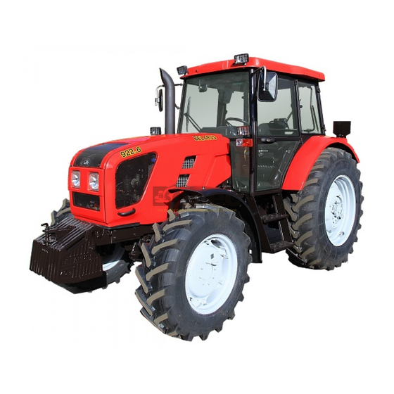
Tractor “BELARUS-922.6” is a general-purpose wheeled tractor of traction class 1.4 with the wheel arrangement 4X4. Basic physical configuration of tractor “BELARUS-922.6” is shown in Figure 1.1.1. -
Page 12: Technical Specifications
922.6-0000010 OM 1.2 Technical specifications Main parameters and specifications of tractor BELARUS-922.6» are given in table 1.1.1. Table 1.1.1 Parameter Parameter value for tractor (specification) designation “BELARUS-922.6” 1 Traction class according to GOST 27021 2 Rated traction force, kN 3 Engine а) model... - Page 13 922.6-0000010 OM Table 1.1.1 continued Parameter Parameter value for tractor (specification) designation “BELARUS-922.6” 8 Permissible load on axles, kN: а) on front b) on rear 9 Max weight of the trailer, kg а) without brakes 2100 b) with independent brake...
- Page 14 922.6-0000010 OM Table 1.2.1 finished Parameter Parameter value for tractor (specification) designation “BELARUS-922.6“ 20 Working equipment: а) rear power take-off shaft: 1) rated speed of PTO shaft end with the ground-speed drive on, rpm: - position I (under the engine crankshaft...
-
Page 15: Tractor Composition
922.6-0000010 OM 1.3 Tractor composition Tractor framework is semi-frame. The undercarriage of the tractor includes driving front and rear wheels with low- pressure pneumatic tires. Front wheels are steering. Rear wheels can be twinned by means of a spacer. The tractor is equipped with a 4-stroke piston six-cylinder inner combustion engine with in-line vertical arrangement of cylinders, with direct injection of diesel fuel and com- pression ignition, corresponding to environmental requirements of Stage 4. -
Page 16: Vibration Level At The Operator's Working Place Of The Tractor "Belarus-922.6
PTO and FDA drive, on the engine control system board. 1.4 Vibration level at the operator's working place of the tractor “BELARUS- 922.6” Vibration level at the operator's seat complies with the Council Directive 78/764/ЕEС. -
Page 17: Noise Level At The Operator's Working Place Of The Tractor "Belarus-922.6
922.6-0000010 OM 1.5 Noise level at the operator's working place of the tractor “BELARUS-922.6” Noise level at the operator's workplace conforms to Directive 2009/76/ЕС, Appendix 2, and does not exceed the value 86 dB (A). External noise level conforms to Directive 2009/63/ЕС... - Page 18 922.6-0000010 OM Serial number Number of gear box (to the left as viewed in the direc- tion of tractor motion) Clutch configuration number Clutch case Transmission and rear axle serial number on tractors with hydrau- lic lift (to the right as viewed in...
-
Page 19: Controls And Instruments
922.6-0000010 OM 2 CONTROLS AND INSTRUMENTS 2.1 Layout of controls and instruments of the tractor Controls and instruments located in the tractor cab are shown in Figure 2.1.1. Figure 2.1.1 – Tractor controls and instruments... -
Page 20: Switches Of The Instrument Board
922.6-0000010 OM To the Figure 2.1.1 – Layout of controls and instruments of the tractor: 1 – place for radio receiver (car stereo) installation; 2 – sun visor; 3 – recirculation shutters; 4 – button switch unit of upper shield; 5 - handle to control the cab heater valve; 6 - cab lamp with switch;... - Page 21 922.6-0000010 OM The layout of key positions of the starter and instruments disconnect switch is given in Figure 2.2.2 and on the informational plate of the switch. Figure 2.2.2 – Layout of key positions of the starter and instruments disconnect...
- Page 22 922.6-0000010 OM Multifunctional under-wheel switch on the right 3 (Figure 2.2.1) provides the engage- ment of two-speed windscreen wiper and washer. The windscreen wiper is activated by moving under-wheel switch lever 3 (fig. 2.2.1) from "off" position (“0” position according to fig. 2.2.4) into “a” position (first speed) or “b”...
-
Page 23: Upper Shield Unit Of Button Switches
922.6-0000010 OM 2.3 Upper shield unit of button switches and rear wiper switch 1 – beacon switch; 2 – cab fan switch; 3 – front working lights switch; 4 – rear (inner) work- ing lights switch; 5 – rear (outer) working lights switch; 6 – rear screen wiper and washer; 7 –... -
Page 24: Cab Heater And Fan Control
922.6-0000010 OM 2.4 Cab heater and fan control Cab heater and fan controls are shown in Figure 2.4.1. 1 – heater valve knob; 2 – hose; 3 – clamp; 4 – fitting; 5 – deflectors; 6 – recirculation shut- ter; 7 – cab fan switch. -
Page 25: Conditioner Control
922.6-0000010 OM Conditioner control 2.5.1 Conditioner control in the conditioning mode Note: Against order the tractor can be equipped with an air conditioner instead of a cab heater and fan. The air conditioner control panel is located on the heater panel. -
Page 26: Cab Ventilation
922.6-0000010 OM ATTENTION: WHEN OPERATING IN THE HEATING MODE, SWITCH 2 (FIGURE 2.5.1) SHALL BE COMPLETELY OFF TO PREVENT THE COOLING SYSTEM AND THE HEATING SYSTEM FROM SIMULTANEOUS OPERATION! 1 –deflectors, 2 – knob of heater valve. Figure 2.5.2 – Assembly of heater valve 2.5.3 Cab ventilation... -
Page 27: Instrument Board
922.6-0000010 OM 2.6 Instrument board Instrument board 13 (Figure 2.1.1) includes five gauges with five signal lamps as shown in Figure 2.6.1. 1 – signal lamp of emergency air pressure in the pneumatic system; 2 – gauge to indi- cate air pressure in the pneumatic system; 3 – pilot lamp of additional accumulator battery charge (not usable);... - Page 28 922.6-0000010 OM ATTENTION: IF THE VOLTAGE GAUGE INDICATES ABSENCE OF AB CHARGE, CHECK THE STATE AND TENSION OF THE GENERATOR DRIVE BELT! 2.6.3 The scale of the gauge indicating fuel volume in tank 6 (Figure 2.6.1) has divi- sions “0-1/4-1/2-3/4-1”. Signal lamp 6 (orange color) is built in the gauge scale, which lights up when fuel volume in the tank drops below 1/8 of the total tank volume.
-
Page 29: Pilot Lamps Unit
922.6-0000010 OM 2.7 Pilot lamps unit 2.7.1 General information Pilot lamps unit 14 (Figure 2.1.1) includes five lamps. The allocation scheme is shown in Figure 2.7.1. 1 – pilot lamp to indicate that the air cleaner filter is clogged to the max. (orange col- or);... -
Page 30: Functioning Algorithm Of Pilot Lamp To Indicate Operation Of Heating Plugs
As a means of start facilitation, heating plugs (HP) are used in tractors “BELARUS – 922.6” which are mounted in the cylinder unit head. For individual control of heating plug operation modes and indication of their operation, a heating plug controller unit is used. -
Page 31: Integrated Indicator And Integrated Indicator Control Panel
922.6-0000010 OM 2.8 Integrated indicator and integrated indicator control panel 2.8.1 General information Integrated indicator 15 (Figure 2.1.1) (further in the text II) and integrated indicator programming panel 19 (Figure 2.1.1) (further in the text IICP) display information on opera- tional parameters of systems and units of the tractor and provide operator with data on vio- lation of operation or breakdown of any system. -
Page 32: Assignment And Operation Principle Of Integrated Indicator Gauges
922.6-0000010 OM Control panel 19 (Figure 2.1.1) allows to carry out manual programming of the indica- tor with buttons “Parameter” and “Value” (see Figure 2.8.2), and also to change the mode of showing data entered on the multifunction display with “Mode” button. The “Mode” button is also used to enter a non-fixed parameter value when programming the device. - Page 33 The range of engine time in- dications is from 0 to 99999 hours. Rear In this mode an exact rotation speed of speed, rpm the rear power takeoff shaft end is shown depending on the signal from RPTO speed sensor. “BELARUS-922.6” tractor has no...
- Page 34 In this mode an exact rotation speed of speed, rpm the front power takeoff shaft end is shown depending on the signal from FPTO speed sensor. “BELARUS-922.6” tractor has no RPTO installed, that’s why “0” value will al- ways be shown in this mode. Instant fuel flow,...
-
Page 35: Pilot Lamps Of The Integrated Indicator
922.6-0000010 OM Testing fre- If there is no signal coming from the quency fuel vol- frequency fuel volume sensor for two sensor sec. a message “FUEL” is displayed (FFVS) workability on the screen. Testing of CAN- If there are no signals through CAN-... -
Page 36: Description Of Testing The Integrated Indicator Performance
922.6-0000010 OM 2.8.4 Description of testing the integrated indicator performance Each time the power supply is on, testing of needle pointers and scale elements of the rear PTO indicator is carried out in the integrated indicator. In this case the indicator needle pointers move away from zero marks for one sec. - Page 37 - for “ZV2” – from 0 to 99; - for “V” – from 0 to 1000. The list of programmed parameter values for tractors “BELARUS-922.6” (graphic ex- amples of parameter presentations and their values on the multifunction indicator in the...
- Page 38 A PTO speed sensor is not mounted on tractors “BELARUS-922.6”. Readout of RPTO revolu- tions is carried out with the help of PTO speed sensor. Considering this, the value of “0” shall be set.
-
Page 39: Information Display And Engine Control System Panel
922.6-0000010 OM 2.9 Information display and engine control system panel 2.9.1 General information Information display 4 (Figure 2.9.2) is designed to display engine actual parameters, indication of the engine electronic control system (EECS) faults and SCR parameters. When the key of starter and instrument switch is set into “I” position (Figure 2.2.2) the supply voltage is delivered to the engine electronic control system. - Page 40 922.6-0000010 OM Monitor buttons 1, 2, 3, 4, 5 (Figure 2.9.1) are of multifunctional purpose. When pressing any of buttons 2, 3, 4 during the monitor operation, an image of button panel 6 appears on the screen, the icons denoting the current functions of each button. Pressing button 1 on the moni- tor activates the main three-segment image on the screen.
- Page 41 922.6-0000010 OM Table 2.9.1 – Lift of parameters of four-segment and graphic indication of engine operation Pos. Four-segment Graphic Parameters Symbol imaging imaging Electric voltage directly on terminals of information monitor connection, V Voltage on the accumulator battery terminals, measured by the engine electronic control unit, V...
-
Page 42: Engine Control System Panel
922.6-0000010 OM 2.9.4 Engine control system panel Engine control system panel 5 (Figure 2.9.2) includes button switch of testing activa- tion 1, fault detecting annunciator 2, socket for additional equipment 3, information display 4, socket to attach coupled implements 6 (12V/25A), testing jack 7. The electric circuit dia- gram of the engine electronic control system is given in Annex A. -
Page 43: Steering
2.10 Steering 2.10.1 General information “BELARUS-922.6” tractors are equipped with hydrostatic steering control (HSC), de- signed for controlling the rotation of guide wheels and reduction of effort at the steering wheel while the feed pump is running. When the engine is stopped, the HSC feed pump, driven by the engine crankshaft, does not feed the hydraulic system of the HSC and it is automatically shifted to a manual mode, which requires greater effort on the steering wheel to turn the tractor. -
Page 44: Switching Of Ranges And Gears On Gb
(GB 14F+4R ). Against order BELARUS-922.6 tractor can be equipped with a transmission with a syn- chromesh gearbox with double-lever control and a reverse gear (GB 7F+6R). Reduction gear (reverse gear) is controlled mechanically, using a lever on the left side of the instrument panel facing. - Page 45 RANGES AND GEARS SHALL BE SWITCHED WHEN THE TRACTOR IS COASTING AND THE COUPLING CLUTCH IS FULLY DEPRESSED! The table with a speed diagram on standard configuration tires of BELARUS-922.6 tractor with a reduction gear is attached to the right cab window and is shown in Figure 2.14.2.
-
Page 46: Gears Shifting In Transmission With Reverse Gear
922.6-0000010 OM 2.14.3 Gear switching in the transmission with a reverse gear group Gear shifting is carried out by three levers: GB range shifting lever 6 (Figure 2.14.3), gear shifting lever 3 and reverse gear control lever 1. Selection of required ranges, gears as well as reverse gear passes (a forward travel pass has a "forward"... -
Page 47: Control Panel For Rear Axle Dl And Rpto
Figure 2.14.4. Figure 2.14.4 – Speed diagram for BELARUS-922.6 tractors with a reverse gear group 2.15 Control panel for rear axle DL and rear PTO Elements of control panel of rear axle DL and rear PTO are shown in Figure 2.15.1. -
Page 48: Rear Pto Control
922.6-0000010 OM skidding. In the automatic mode the differential locks in linear movement and unlocks, when the guide wheels turn by an angle of more than 13°. Pressing the right and/or left brake pedal unlocks the differential. “DL positive activation” is carried out by pressing the lower part of switch 7. It’s posi- tion is non-fixed. -
Page 49: Tractor Operation Without Using Rear Pto
922.6-0000010 OM To set the necessary PTO rotation frequency unscrew bolt 1 by one turn, set arm 2 into position “I” or “II” and tighten bolt 1. ATTENTION: CHANGE THE PTO FREQUENCY ONLY WITH THE ENGINE DIS- ENGAGED! Coupling clutch housing Gearbox 1 –... -
Page 50: Control Of Rear Lift Linkage (Rll)
922.6-0000010 OM ATTENTION: WHEN OPERATING ON ROADS WITH HARD SURFACE, IT IS RE- QUIRED TO DISENGAGE THE FDA DRIVE IN ORDER TO PREVENT INCREASED WEAR OF FRONT WHEEL TIRES! TRACTOR OPERATION WITH FDA DRIVE ENGAGED WHEN THE TRAVELLING SPEED IS ABOVE 13 KM/H IS FORBIDDEN! -
Page 51: Hll Pump Control
922.6-0000010 OM depth soil) through upper link. Hydraulic system responds to these changes by lifting and lowering of an implement in order to maintain the intended drawbar power at a fixed level. The system responds to compressive force and extension force in the upper link i. e. it is double action system. -
Page 52: Hll Valve Group Section Control (Remote Cylinders)
“Neutral” position; - "Float" – rearmost fixed position; Distribution valve RP70-822.1 or RP70-822 outputs positioning and connection to the external consumers on tractors “BELARUS-922.6” diagram is presented on Figure 2.20.2. -
Page 53: Electric Cutout Fuses
922.6-0000010 OM Figure 2.20.2 - Distribution valve RP70-822.1 or RP70-822 outputs positioning and connection diagram. 2.21 Cutout fuses 2.21.1 General information Electric cutout fuses are intended for the protection of electrical lines against over- loads and short circuit. WARNING: TO AVOID BURNING OF TRACTOR WIRING NEVER USE FUSES WITH CURRENT RATING HIGHER THAN RATINGs SPECIFIED IN THIS SECTION. - Page 54 922.6-0000010 OM near each fuse are intended for indication of a corresponding fuse blow out. A signal led lamp of green color 3 indicates the switching unit turning on. а) BKA-7.3722-02 b) BK-1-02 1 – cutout fuse; 2 – signal led lamp of red color; 3 – signal led lamp of green color; 4 – electro- magnetic relay;...
- Page 55 922.6-0000010 OM Tables of fuses and relay assignment shown in Figure 2.21.3 are stuck from inside to the upper plastic cap 2 (Figure 2.21.1) from the windscreen side. The information on fuses and relay assignment as well as fuse ratings is given in ta- bles 2.21.1 and 2.21.2...
- Page 56 922.6-0000010 OM Table 2.21.2 – Relay assignment Relay desig- Relay assignament nation К1 Radioset (stereo-recorder) К2 Rear working lights (a pair of inner lights) К3 Conditioner or heater К4 Rear working lights (a pair of outer lights) К5 Front working lights (on the roof) К6...
- Page 57 Apart from fuses located in the switching unit and shown in Figure 2.21.3, in order to protect the electrical equipment power circuits the fuses are installed in the on-board circuit of BELARUS-922.6 tractor. The fuses have the following locations in the engine compart- ment: - In the coarse fuel filter mounting location;...
-
Page 58: Fuses For Electronic Systems Of Dl And Pto
922.6-0000010 OM 1 – supply fuse of the starter relay (located inside switching unit) and accumulator battery remote control circuit with rated value of 80 А; 2 – heating plug supply fuse with rat- ed value of 80А; 3, 4 –switching unit supply fuse with rated value of 60A; 5 – fuse block. -
Page 59: Fuses For Engine Electronic Control System
922.6-0000010 OM - Connect the DL and PTO ECSs fuses if equipped with mechanical control of the GB gear (standard configuration), which is represented in Figure 2.21.10; - Connect the DL, PTO and GB gear ECSs fuses and manual gear if equipped with electrohydraulic control (custom configuration), as is illustrated in Figure 2.21.11. - Page 60 922.6-0000010 OM 1 – accumulator battery; 2 – fuse block; 3 –60 А fuse for AB remote control switch and radio-recorder power supply; 4 – EECS constant supply fuse (at any position of the storage battery switch) with rated value of 60А; 5 – additional suspended fuse of control switch and radio-recorder power supply with rated value of 25 А;...
-
Page 61: Cab Locks And Handles
922.6-0000010 OM 2.22 Cab locks and handles 2.22.1 Cab door locks Left and right doors of tractor cab are secured with locks 4 (Figure 2.22.1). Lever 5 serves to open the left and right cab doors from inside the cab. Moving lever 5 backwards unlocks the door. -
Page 62: Rear Screen Opening
922.6-0000010 OM 2.22.3 Rear screen opening To open the rear screen, turn handle 1 (Figure 2.22.3) to the left (as viewed along tractor movement) and holding handgrip 2, push rear screen 3 until the screen is fixed in the open position. -
Page 63: Seat And Its Adjustments
922.6-0000010 OM 2.23 Seat and its adjustments 2.23.1 General information The seat has a mechanical suspension, consisting of a laminated torsion bar and a shock absorber of bidirectional operation. A “scissors”-type guiding mechanism ensures strictly vertical movement of the seat. A dynamic seat stroke is 90 mm. -
Page 64: Control Of The Pneumatic System Compressor
922.6-0000010 OM 2.24 Control of the pneumatic system compressor Handle for the pneumatic system compressor engagement 1 (Figure 2.24.1) has two positions: - left (the arrow on the handle is directed forward as viewed along tractor move- ment) – “compressor off”, - right (the arrow on the handle is directed backward to tractor cab) –... -
Page 65: Connector Elements Of The Electrical Equipment
Thus, the used electrical in- struments shall have a certificate of electromagnetic compatibility according to international requirements. Tractor "BELARUS-922.6", apart from the socket for the trailed agricultural equip- ment connection, has additional electrical sockets. The installation of these sockets is shown in Figure 2.9.2. -
Page 66: Connection Of Additional Electrical Equipment Of Coupled Machines
922.6-0000010 OM 2.25.3 Connection of additional electrical equipment of coupled machines Beside connecting the coupled machinery EE to socket 3 and 6 ( Figure 2.9.2 ) it is al- lowed to connect electrical equipment of coupled machines to the following elements of tractor electrical equipment: 1. -
Page 67: Indication Of Scr System Operation
922.6-0000010 OM 2 .26.2 Indication of SCR system operation To look through SCR system parameters, it is required to press any button of the mon- itor, except for button 5 (Figure 2.9.1), when the monitor is in the display mode of engine pa- rameters. - Page 68 922.6-0000010 OM SCR parameters are set forth on four pages. By pressing button 2 (Figure 2.26.4) the pages with SCR parameters are turning: - first page – clauses 18, 19, 23 of table 2.9.1; - second page – clauses 20, 21, 24 of table 2.9.1;...
- Page 69 922.6-0000010 OM In case of lowering reagent AdBlue level less than 28% of the tank filling volume, there pops up a symbol on the monitor in the flashing mode, shown in Figure 2.26.7. In case of lowering reagent AdBlue level less than 4% of the tank filling volume, there pops up a symbol on the monitor in the mode of continuous glow, shown in Figure 2.26.7.
-
Page 70: Intended Use Of Tractor
922.6-0000010 OM 3 INTENDED USE OF TRACTOR 3.1 Safety measures while preparing tractor for operation Strict observance of safety requirements ensures safe operation of the tractor and improves its reliability and durability. Only persons not younger than 17, having a driving license for tractors of drawbar category 1.4, being briefed on accident and fire prevention, may be admitted to operate the... -
Page 71: Tractor Use
3.2.2 Engine start and preparation for it To start the engine of tractor “BELARUS-922.6”, do the following: - engage the tractor parking brake; - if required, fill in fuel and bleed the fuel delivery system to remove air from it;... - Page 72 922.6-0000010 OM 2) Switch off range «II» (increased). To do so, move the gear shifting lever from posi- tion «II» (increased) in the direction of range «I» (decreased) until it stops. At the same full integration of a range of «I» is required.
-
Page 73: Start Of Tractor Movement, Gb Shifting
Before starting the movement, define a necessary speed of tractor movement. The speed diagrams of the tractor “BELARUS-922.6” with tires of basic configuration is given in the instruction table attached to the cab right window and also in subsection 2.14 “GB range and gear switching”. -
Page 74: Tractor Stop
922.6-0000010 OM TO TAKE OFF FOOT FROM PEDAL AT THE END OF PEDAL TRAVEL, TO REGENERATE PLAY IN HYDRAULIC DRIVE OF CLUTCH CONTROL. ATTENTION: IN CASE OF ERROR (FAILURE) APPEARANCE, TIME METERS TURN ON IN THE SCR SYSTEM UP TO THE ACTIVATION OF ENGINE TORQUE LIMITING (EASY LIMITING OF 25% AND HEAVY LIMITING OF 50%). -
Page 75: Engine Stop
922.6-0000010 OM 3.2.5 Engine stop ATTENTION: BEFORE STOPPING THE ENGINE, LOWER LIFT LINKAGES UNTIL THEY REACH THE GROUND, IF THEY ARE UPLIFTED; LET THE ENGINE RUN AT (1000±100) RPM FOR 3 TO 5 MINUTES. THIS ALLOWS REDUCING ENGINE COOLANT TEMPERATURE! - Page 76 955 rpm. The power transmitted by the rear PTO shaft ends 1c / 1/2 and maximum permissible torque on the PTO shaft ends 1c / 1/2 of the tractor "Belarus-922.6" is given in Table 3.2.2. Table 3.2.2 PTO shaft end Max.
-
Page 77: Selection Of Optimal Inner Pressure In Tires Depending On Operational Conditions And Load On Tractor Axles
922.6-0000010 OM If the cap is secured with bolts, then in order to work with the PTO remove the protective cap covering the shaft end. To do so, unscrew 2 fastening bolts. After the operation with PTO is finished, it is necessary to put the cap back in its place by screwing up both bolts. - Page 78 MD-214). Rates of admissible loads on single tires of tractors “BELARUS-922.6” for selection of opera- tion mode at various tire inner pressure and speed are given in table 3.2.3.
-
Page 79: Tire Inflation
922.6-0000010 OM Pressure shall be set in “cold” tires. Acceptable limit deviations in the tires are (± 10 kPa) acc. to pressure gauge indications. Performing operations which require large pulling force on the hook, set the pressure as for the speed of 30 km/h. When performing transport operations on roads with hard surface, increase 160 kPa (for tires 18.4R34, 15.5R38) and 190 kPa (for... -
Page 80: Rear Wheel Track Formation
922.6-0000010 OM 1 – pneumatic compressor; 2 – winged nut or cap; 3 – union; 4 – tire inflation valve Figure 3.2.3 – Tire inflation valve installation 3.2.9 Rear wheel track formation 3.2.9.1 Rear wheel track formation, installed on terminal hubs. -
Page 81: Track Formation Of Rear Wheels, Mounted On Cone-Shaped Hubs
922.6-0000010 OM - mount the wheel and tighten nuts 1 with a torque from 300 to 350Nm; - set the other wheel track in the same way. 1 – nuts retaining wheel on hub; 2 – bolt retaining hubs on semiaxles. - Page 82 922.6-0000010 OM а) Hub configuration b) Bolt tightening diagram for bolts retaining hub to semi-axle 1 – tie bolts; 2 – hub group housing; 3 – upper bushing; 4 – lower bushing; 5 – dis- mounting holes. Figure 3.2.7 – Rear wheel hub group The rear wheel track with the wheels of basic configuration 18.4R34 is changed by...
-
Page 83: Rear Wheel Twinning
922.6-0000010 OM Note – For information on track formation rules for rear wheels of different configura- tion contact your dealer. 3.2.10 Rear wheel twinning With an aim to improve gripping properties of the tractor when coupled with heavy agricultural implements on soil with low bearing capacity, rear wheel twinning with use of spacers is provided. - Page 84 922.6-0000010 OM End of Table 3.2.7 The rim is turned by 180°. The disk mates 1835 1955 with the support outer surface. The disk mates with the support outer 1585 1705 surface. The disk mates with the support inner 1685 1805 surface.
-
Page 85: Safety Measures While Tractor Operation
922.6-0000010 OM 3.3 Safety measures to be taken when operating the tractor 3.3.1 General safety measures to be taken when operating the tractor The cab complies with category 2 under EN 15695-1:2009. This category cab en- sures protection against dust, but not against sprays and vapor – the tractor shall not be used under conditions, requiring protection against sprays and vapor. - Page 86 922.6-0000010 OM Do not work under raised agricultural implements. Do not leave implements uplifted when stopping for a long time. Trailers attached to the tractor shall have a braking system, ensuring: - trailer brake on movement; - brake engagement in case of trailer detachment from the tractor;...
-
Page 87: Fire Safety Measures
922.6-0000010 OM Do not work under raised agricultural implements. Do not leave implements uplifted when stopping for a long time. Before lifting and lowering a hinged agricultural implement and also when turning the tractor make sure there is no danger of catching somebody or stumbling on the hurdle. - Page 88 922.6-0000010 OM Never add petrol or mixtures to engine fuel. This combination may create increased danger of inflammation or explosion. Places for tractor parking, storing of fuel and lubricants shall have a plowed around band of not less than 3 m width and also be provided with fire extinguishing means.
-
Page 89: Tractor Final Assembly And Run-In
922.6-0000010 OM 3.4 Tractor final assembly and run-in 3.4.1 Tractor final assembly “BELARUS-922.6” tractors are supplied to a consumer ready assembled, final as- sembly is not required. 3.4.2 Technical maintenance before tractor run-in Before placing a new tractor in operation, do the following: - carry out the de-preservation procedure of the tractor according to Subsection 7.6... -
Page 90: Technical Maintenance During Tractor Run-In
922.6-0000010 OM ATTENTION: IT IS OBLIGATORY THAT YOU CARRY OUT TRACTOR RUN-IN FOR 30 HOURS! LOAD THE TRACTOR UP TO 80 % OF ITS RATED POWER BEFORE THE FIRST TECHNICAL MAINTENANCE (TM-1) (125 HOURS)! Start the engine. Let the engine run at idle speed for five minutes with gradual in- crease of the rotation speed up to 1600 rpm, then run in under load for 30 operation hours. -
Page 91: Emergency Actions
922.6-0000010 OM - check the state of accumulator batteries, clean terminal connections and ventilation holes; - check brake fluid level in the main cylinder tanks of hydrostatic clutch drives and in the tanks of service brakes, if necessary add it;... -
Page 92: Coupling Of Implements
Selection and buying of agricultural implements (fertilizer distributors, plows, motor cultivators, harrows, seeding machines, rotary tooling and other implements) for tractors “BELARUS-922.6” is carried out by the customer individually according to their needs, and with consideration of the implement and tractor performance specifications, and also local conditions i.e. -
Page 93: Types Of Implements Coupled With Tractor "Belarus-922.6
922.6-0000010 OM A tractor operator is personally responsible for observance of traffic regulations and safety requirements as well as safety measures and correct tractor “BELARUS-922.6” use, specified in this operation manual. Service staff qualification requirements for tractor “BELARUS-922.6” operation: - only qualified service staff trained for safety arrangement and precautions, having tractor driving license of due form and having admission to operate the specific tractor, is allowed;... -
Page 94: Lift Linkage
MENTS, FOR PERFORMANCE OF DIFFERENT WORK WITH THE TRAVEL SPEED NOT MORE THAN 15 KM/H! RLL sizes and design of tractors “BELARUS-922.6” make it possible to couple all im- plements having the corresponding dimensions of the coupling triangle connecting elements shown in RLL diagram. - Page 95 922.6-0000010 OM To ensure the required position of the implement, the following RLL vertical and hori- zontal adjustments by means of upper link, lifting rods and buckles are provided: 1. Adjustment of the upper link length. It is carried out in order to ensure equal soil penetration of operating parts (running depth leveling of operating parts located one after another in the direction of tractor move- ment).
- Page 96 922.6-0000010 OM TION, CONTACT THE MANUFACTURER OR SELLER OF THE IMPLEMENT FOR IN- FORMATION! Rear lift linkage diagramm of “LL-2” type Figure 4.3.1 – Basic parameters and coupling dimensions of RLL Table 4.3.1 – LL-2 Standard size (configuration) of the device (Figure 4.3.1)
-
Page 97: Rll Components Adjustment Rules
4.3.3.1.1 General information Buckles are used to limit side sway of lower links of the lift linkage both in transport and in operating position. The tractors BELARUS-922.6 with hydraulic lift can be equipped with telescopic buckles or outer turnbuckles. ATTENTION: IN CASE OF CHANGE OF LENGTH OF A LIFTING ROD IT IS NEC- ESSARY TO ADJUST BUCKLE LOCKS AGAIN IN TRANSPORT AND OPERATING PO- SITIONS. - Page 98 922.6-0000010 OM Partial blocking of buckles in operating position should be made in the following way: - turning screw 2 (Figure 4.3.4), set handle 3 in the middle of flattened surface “А”; - derive forelock key 5 from the buckle;...
-
Page 99: Outer Turnbuckles
922.6-0000010 OM Full blocking of buckles in transport position shall be made as follows: - if buckles were fully blocked in operating position, you should check side-sway range of the machine (implement) while it is lifted in up position, which shall not exceed 20 mm in each side. -
Page 100: Lifting Rod
922.6-0000010 OM machine (implement) it is required to shorten the turnbuckles 2 length as much as possible by turning of the central element A. After doing so, check side-sway range of the machine (imple- ment) while it is lifted in up position, which shall not exceed 20 mm in each side. Adjust the turnbuckles 2 length when necessary, by turning central element A of the turnbuckles;... -
Page 101: Upper Link
4.3.3.4.2 Telescopic lower links and twin crossbar Belarus-922.6 tractors can be equipped with enforced RLL and telescopic lower links in- stead of RLL with solid lower links. If it is necessary, you can regulate step by step the length of ±... -
Page 102: Attachment Of Implements To A Tractor
922.6-0000010 OM Twin crossbar DH-ZH-01 6 (Figure 4.3.9) with kingpin 7 is optional supplied to the tele- scopic lower links for operation with mounted agricultural implements. Tips 5 are mounted in- stead of the links rear ends 4 (an eye is mounted on the middle hole of twin crossbar tips 5). In this configuration the distance between the PTO end and the kingpin (coupling point) makes ±... -
Page 103: Drawbar Hitches
DH-1ZH-01 (twin crossbar) can only be installed on a tractor with RLL, equipped with telescopic lower links. Tractor “BELARUS - 922.6” has special-purpose rear mounting device of lift type in the form of guide plates with several borings fixed to the rear joint face of a rear axis body. -
Page 104: Drawbar Hitch Non-Rotatable Towing Yoke (Dh-2V)
922.6-0000010 OM 4.4.2 Drawbar hitch non-rotatable towing yoke (DH-2V) Figure 4.4.1 – Installation variant diagram of short towing yoke Table 4.4.1 – Basic parameters and coupling dimensions of towing yoke DH type Yoke 1 Variant Yoke acc. to ISO Yoke acc. to GOST... -
Page 105: Drawbar Hitch Rotatable Towing Yoke (Dh-Зv)
922.6-0000010 OM 4.4.3 Drawbar hitch rotatable towing yoke (DH-ЗV) Figure 4.4.2 – Installation variants scheme of towing yoke Table 4.4.2 – Basic parameters and coupling dimensions of towing yoke DH type Yoke 1 Mounting location Rear lifting device 2 Design features... -
Page 106: Drawbar Hitch "Python" (Dh-2R)
922.6-0000010 OM 4.4.4 Drawbar hitch “Python” (DH-2R) Figure 4.4.3 – Installation variants scheme of “python” DH Table 4.4.3 – Basic parameters and coupling dimensions of drawbar hitch “python” DH type “Python” 1 Mounting location Rear lifting device 2 Design features... -
Page 107: Towing Bar (Dh-1М-01)
922.6-0000010 OM 4.4.5 Towing bar (DH-1М-01) Figure 4.4.4 – Installation variants scheme of towing bar Table 4.4.4 – Basic parameters and coupling dimensions of towing bar DH type Towing bar First position 1 Variant 1 Variant At the bottom of rear axis body and rear... -
Page 108: Drawbar Hitch Crossbar (Dh -1)
922.6-0000010 OM 4.4.6 Drawbar hitch crossbar (DH -1) Figure 4.4.5 – Installation scheme of crossbar Table 4.4.5 – Basic parameters and coupling dimensions of crossbar DH type Crossbar 1 Mounting location On a suspension axis of rear lift link- 2 Design features... -
Page 109: Drawbar Hitch Twin Crossbar (Dh-1Zh-01)
922.6-0000010 OM 4.4.7 Drawbar hitch twin crossbar DH-1ZH-01 Figure 4.4.6 – Installation scheme for twin crossbar Table 4.4.6 – Basic parameters and coupling dimensions of twin crossbar DH Type Twin crossbar 1 Mounting location On rear ends of telescopic lower links... -
Page 110: Determining Max. Allowable Vertical Load On Tractor Dh Depending On Rear Tires
922.6-0000010 OM 4.4.8 Determining max. allowable vertical load on tractor DH depending on rear tires standard size, type of applicable draw hitch and tractor travel speed The values of the vertical load on the tractor DH depending on the rear tires standard size, applicable DH type and tractor travel speed are shown in Table 4.4.7... -
Page 111: Usage Patterns Of Tractor Hydraulic System For Drive Of Operating Parts And Other Elements Of Hydraulically-Powered Coupled Machines And Implements
(uplift) of the operating parts. The main characteristics of tractor “BELARUS-922.6” HLL for drive of operating parts and other elements of coupled hydraulically-powered implements and machines are shown... -
Page 112: Front Ballast Weights Installation
922.6-0000010 OM Table.4.5.1 – Tractor “BELARUS-922.6” hydraulic drive specifications Parameter Parameter description value (characteristic) Side Rear 1 Paired hydraulic outputs Two pairs One pair 2 Oil pipe for free draining into tank (free drain line) 3 Total oil consumption through hydraulic out-... -
Page 113: Trailer Brake Drive
PREVENTING THE TRACTOR FROM SELF-MOVEMENT! 4.7.2 Double-line pneumatic drive of trailer brakes Tractors BELARUS-922.6 in base-line configuration are equipped with double line pneumatic drive providing brake control of trailers and agricultural machines, equipped with two-line pneumatic brake drive. The pneumatic drive is used also for tires charging and oth- er purposes where energy of compressed air is required. -
Page 114: Determination Of Pto Shaft And Cardan Shaft Applicability
SAFETY CLUTCH EXCEEDS THE PERMISSIBLE PTO SHAFT END TORQUE, SUCH IM- PLEMENT MUST NOT BE COUPLED WITH THE TRACTOR. Note - The maximum permissible torques for all kinds of BELARUS-922.6 PTO shaft ends are given in section 3.2.7 "PTO use". - Page 115 922.6-0000010 OM SHAFT MOUNTING, STOP THE ENGINE, GET THE IGNITION KEY OUT OF THE STARTER AND INSTRUMENTS SWITCH, AND ENGAGE THE PARKING BRAKE! ATTENTION: TRACTOR MANUFACTURER SHALL NOT BE RESPONSIBLE FOR THE COUPLED IMPLEMENTS CARDAN SHAFTS FAILURES. CARDAN SHAFTS SPECI-...
- Page 116 8. When the cardan shaft is used for the first time, it is necessary to check the cardan shaft length, and to adjust it to the operating conditions with tractors “BELARUS-922.6” if needed. For more detailed instructions on cardan shafts - see the technical documentation enclosed.
- Page 117 922.6-0000010 OM 11. After cardan shaft coupling, bring all protective devices into a proper condition, including fixing of the guard shaft housing with the chains to prevent rotation, as shown in Figure 4.9.3. 12. If necessary, limit the RLL height of the extreme upper position while the imple- ment uplifting.
-
Page 118: Ways Of Changing Drawbar Features And Passing Ability Of The Tractor
Note – Pneumatic pressure rate in the front and rear tires of the tractors “BELARUS - 922.6” under actual load is shown in subsection 3.2.8 “Selection of optimal internal pressure in tires depending on the operating conditions and load on tractor axles”. -
Page 119: Features Of Tractor Application In Special Conditions
4.11.3 Operation in a forest IT IS FORBIDDEN TO USE TRACTOR “BELARUS-922.6” FOR OPERATION IN A FOREST AS WELL AS FOR CLAMSHELL LOADER COUPLING, TRAILING EQUIPMENT, SPECIAL-PURPOSE FORESTRY MACHINERY DESIGNED FOR GATHERING, LOADING,... -
Page 120: Determination Of Total Weight, Loads On Front And Rear Axles, Tires Holding Ca
922.6-0000010 OM 4.12 Determination of total weight, loads on front and rear axles, tires holding capacity and the required minimum ballast The amount of load on tractor axles in structure of MTU may be determined by direct weighting on truck scales of the corresponding carrying capacity. - Page 121 922.6-0000010 OM where are calculated loads for tire inflation pressure during operation on сдв. сдв. twinned wheels. Further according to the calculated loads, it is necessary to determine tire pressure (according to subsection 3.2.8 “Selection of tires internal pressure depending on operating conditions and load on tractor axles”).
-
Page 122: Possibility Of Front Loader Installation
Table 4.13.1 – The rules of tractor with loader use Name of indicator (characteristics) Indicator (characteristics) value Standard size of tractor “BELARUS-922.6” 360/70R24 – front, 18.4R34 – rear wheel tires on which loader installation is (i. е. tires of basic configuration or imported tires... - Page 123 922.6-0000010 OM AND ALSO IN CONFIGURATION WITH FRONT AND REAR TIRES OF MINOR CONFIG- URATION. For installation of the complete set of loading equipment openings on a front beam, side members and the tractor clutch coupling case are used. For the purpose of unloading a...
-
Page 124: Safety Measures While Tractor "Belarus-922.6" Operation With The Loader Installed
ATTENTION: INSTALLATION OF MOUNTED FRONT LOADERS OF VARIOUS MANUFACTURERS IS ALLOWED ON TRACTOR “BELARUS-922.6” IF IT IS PROVIDED IN TECHNICAL DOCUMENTATION FOR THESE LOADERS! ATTENTION: FRONT LOADERS WHICH ARE NOT DESIGNED FOR BEING USED TOGETHER WITH TRACTOR “BELARUS-922.6”... - Page 125 922.6-0000010 OM LOADER OPERATION ON THE SLOPE WITH MORE THAN 8° IS FORBIDDEN! Tractor service brake control pedals shall be always interlocked during loader opera- tion. Avoid abrupt start, braking, sharp turns and long-term frictional slip of tires while trac- tor operation with the loader.
-
Page 126: Information On The Tractor Mounting Holes
The mounting holes arrangement scheme for tractor “BELARUS-922.6” is shown in Figure 4.13.2. The parameters of mounting holes are listed in table 4.13.2. - Page 127 922.6-0000010 OM...
-
Page 128: Maintenance
922.6-0000010 OM 5 MAINTENANCE 5.1 General instructions Maintenance service (MS) is necessary for maintaining the tractor in operable state during operational processes. Failure to observe the specified intervals of MS and bad quality of MS may result in reduction of tractor life significantly, increase of failures, engine power loss and increase in expenses for tractor operation. - Page 129 922.6-0000010 OM Types of scheduled maintenance service are shown in table 5.1.1. Table 5.1.1 – Types of scheduled maintenance service Types of maintenance service Intervals, h Maintenance service while operational run-in MS before, during and after tractor run-in (after 30 hours of operation)
-
Page 130: Providing Access To The Components For Maintenance Services
922.6-0000010 OM 5.2 Providing access to the components for maintenance services Before starting any maintenance work it is necessary to remove both sides 9 and 10, open hood 3. To remove sides 9 and 10, proceed as follows: - unscrew 1 bolt 7 and 2 bolts 8;... -
Page 131: Maintenance Procedure
922.6-0000010 OM 5.3 Maintenance procedure Contents of scheduled servicing operations for tractors “BELARUS-922.6” in the course of operation are listed in Table 5.3.1. Table 5.3.1. Periodicity, h Opera- Operation description tion No 8-10 125 250 500 1000 2000 Check oil level in the engine crankcase... - Page 132 922.6-0000010 OM Table 5.3.1 continued Opera- Periodicity, h Operation description tion No 8-10 125 250 500 1000 2000 Check oil level in intermediate bearing of FDA car- dan drive Check / adjust clutch control Carry out maintenance of AB Lubricate HSC hydraulic cylinders hinge joints...
- Page 133 922.6-0000010 OM Table 5.3.1 finished Opera- Periodicity, h Operation description tion No 8-10 125 250 500 1000 2000 Change oil in brake housings, operating in the oil sump Change brake liquid in the clutch control drive Change brake liquid in the brake control drive...
-
Page 134: Scheduled Maintenance Service Operations
922.6-0000010 OM 5.4 Scheduled maintenance service operations 5.4.1 Maintenance service on a shift basis (SBMS) in every 8 – 10 hours of op- eration or per shift 5.4.1.1 General instructions Every 8 – 10 hours of tractor operation or at the end of shift (depending on which comes first), do the following operations: 5.4.1.2 Operation 1. - Page 135 922.6-0000010 OM 5.4.1.4 Operation 3. Check of oil level in the HLL tank Before checking oil level, set the tractor on the flat horizontal ground. Lower RLL links to the extreme lower position. Stop the engine and engage the parking brakes.
- Page 136 922.6-0000010 OM 5.4.1.6 Operation 5. Check of cooling liquid level in the engine cooling system The coolant level in the engine cooling system shall be controlled by fullness of the expansion tank 9 (Figure 5.4.5). The coolant quantity in the expansion tank shall stay at the level of 20 to 30 mm from the expansion tank bottom to the upper edge of the clamp 11 fas- tening the expansion tank 9.
- Page 137 Note – Operation shall be carried out when the tractor is equipped with air conditioner instead of fan-heater. The BELARUS-922.6 tractors have two drainage conditioner pipes, which are located under rear fenders (one pipe for each side), as shown in Figure 5.4.6.
- Page 138 922.6-0000010 OM 1 – rear wheel; 2 – drainage pipe; 3 – rear fender; 4 – middle cab support. Figure 5.4.6 – Location of drainage pipes outputs Water dropping from drainage pipes outputs during air-conditioner operation in the hot weather is а sign of clean drainage pipes. If the water doesn’t drop from drainage pipes dur- ing air-conditioner in the hot weather it is necessary to blow drainage pipes with compressed air.
- Page 139 922.6-0000010 OM 1 – drainage pipe; 2 – heater-cooler output; 3 – heater-cooler. Figure 5.4.8 – Upper chamber Mount the panel of cab upper chamber on place, fasten it with four bolts, put caps and heater valve handle back. 5.4.1.13 Operation 12. Inspect/clean air conditioner condenser Note –...
- Page 140 922.6-0000010 OM 1 – gripper tool; 2 – link. Figure 5.4.9 – Gripper tool of RLL 5.4.1.16 Operation 15. Check breaks functioning in running order, the engine, steer- ing, light/alarm devices operability. Check of condition of electrical cables in the engine...
- Page 141 922.6-0000010 OM and “max” marks, made on the tank housings. If necessary, add brake fluid up to the “max” mark, turning off tank caps 1. To access tanks 2 and 4 open the tractor facing hatch. 1 - tank cap; 2 – main brake cylinder tank; 3 – brake fluid level control sensor; 4 –...
-
Page 142: Maintenance Service In Every 125 Hours Of Operation (Ms-1)
922.6-0000010 OM 5.4.2 Maintenance services in every 125 hours of operation (MS-1) 5.4.2.1 General guidelines Perform the following operations and the operations, listed in this subsection 5.4.2. 5.4.2.2 Operation 20. Check of threaded joint torqueing of wheels mounting Check threaded joint torqueing of wheels mounting shall be carried out one time along with first MS on a shift basis (in 8-10 hours of operation), which is carried out by a customer and then in every 125 hours of operation. - Page 143 922.6-0000010 OM 5.4.2.3 Operation 21. Washing of the tractor and cleaning of the cabin inside Wash the tractor and clean the cabin inside. Before washing the tractor with water jet stop the engine, put the battery disconnect switch in “OFF” position.
- Page 144 922.6-0000010 OM 5.4.2.7 Operation 25. Drain of the sediment from coarse fuel filter To drain the sediment from coarse fuel filter it is necessary to perform the following: - open drain cock 1 (Figure 5.4.15) of coarse fuel filter 3;...
- Page 145 922.6-0000010 OM 1– panel; 2 – screw; 3 – filter. Figure 5.4.16 – Cleaning of the cab ventilation and air heating systems filter ATTENTION: DO NOT SWITCH ON THE FAN BEFORE CLEANING THE FILTERS AT HIGH HUMIDITY OF THE ENVIRONMENT, FOR EXAMPLE IN THE MORNING, AS IT...
- Page 146 922.6-0000010 OM Figure 5.4.17 – Adjustment of air conditioner compressor drive belt tension 5.4.2.10 Operation 28. Check of oil level in intermediate bearing of FDA cardan drive To check the oil level in intermediate bearing 2 (Figure 5.4.18) it is necessary to perform...
- Page 147 922.6-0000010 OM - tighten up nut 22 with a torque from 50 to 70 Nm without letting link 21 turn, cotter pin 24. 2.2 Bleeding of the hydraulic system of clutch control Bleeding of the hydraulic system shall be performed in the following order:\ - unscrew bolt 11а...
-
Page 148: Ms-1, 2Ms-1, Ms-2, Ms-3 And Special Ms
922.6-0000010 OM 2.3 Check of declutching cleanliness After performing the above mentioned adjustments of clutch control, it is required to check declutching cleanliness, for which do the following: - engage the parking brake; - start the engine and set diesel rated speed (1400±100) rpm;... -
Page 149: Operation 33. Check / Adjustment Of Wheel Toe-In
922.6-0000010 OM 1 – hinge joint; 2 – plug; 3 – locking wire; 4 – steering link. Figure 5.4.21 – Maintenance of steering joints 5.4.3.3 Operation 33. Check / adjustment of front wheel toe-in Adjustment of front wheel toe-in is carried out to prevent front tires from premature breakdown. -
Page 150: Operation 41. Check / Adjustment Of Service Brake Control
922.6-0000010 OM 5.4.3.4 Operation 41. Check / adjustment of service brake control 5.4.3.4.1 Check/adjustment of dry friction service brake control ATTENTION: IT IS REQUIRED TO CHECK AND ADJUST THE BRAKE SYSTEM AS WELL AS ELIMINATE ANY FAILURES IN IT ONLY WITH THE ENGINE OFF AND THE... - Page 151 922.6-0000010 OM 4. After making adjustments, fill the drive hydraulic system with brake fluid and bleed the hydraulic system in the following order: - fill tanks 17 and 18 (Figure 5.4.24) of main brake cylinders 16 and 15 with brake flu- id up to the mark “MAX”...
-
Page 152: Check/Adjustment Of Service Brakes Control, Operating In Oil Sump
922.6-0000010 OM - screw in and screw out adjusting rod-bolts 6 and 10 of the right and left service brakes; - lock the rod- bolts. 6. Check the efficiency of service brakes operability during tractor movement along dry road with hard surface with the clutch off. When the interlocked brake pedals are de- pressed with the force of 550 to 600 N, the length of braking path shall not exceed 6,4m with the tractor travel speed of 20 km/h. - Page 153 2 and 13, set and splint pins 4 and 11. 4. Brake cylinders produced by the company CARLISLE (Great Britain) or produced by the company Fenox (Belarus) can be mounted in service brakes control system. On tractors with CARLISLE main brake cylinders after making adjustments, fill the drive hydraulic system with brake fluid and bleed the hydraulic system in the following order: - fill tanks 17 and 18 (Figure 5.4.28) of main brake cylinders 16 and 15 with brake flu-...
-
Page 154: Operation 42. Check / Adjustment Of Parking Brake Control
922.6-0000010 OM 5. Check the value of the unlocked pedals full travel separately applying force of 270- 300 N which shall be within 100 to 120 mm. In case the value of the pedal full travel ex- ceeds the specified limits, it is required to make adjustments doing the following operations: - uncrew counter nuts of rod-bolts 6 and 10 (Figure 5.4.26) by several revolutions;... -
Page 155: General Maintenance Services
922.6-0000010 OM 1, 3, 4, 10 – lever; 2 – quadrant; 5 – adjusting bolt; 6 – locknut; 7 – link; 8 – yoke; 9, 11 – pin. Figure 5.4.27 – Adjustment of parking brake control 5.4.4 General maintenance services 5.4.4.1 General instructions... -
Page 156: Operation 72. Maintenance Of Engine Air Cleaner
922.6-0000010 OM 5.4.4.3 Operation 72. Maintenance of engine air cleaner Maintenance of engine air cleaner should be performed after air cleaner filter indicat- ing lamp gets on, which is located in control indicator unit at instrument board. It means that the filtering element is out of its lifetime. -
Page 157: Seasonal Maintenance Services
922.6-0000010 OM After 3 changes of MFC the master filter element shall also be changed. IT IS FORBIDDEN TO BLOW OFF WITH EXHAUST GASES, RINSE AND DUST OFF MAIN FILTER CARTRIDGE! ATTENTION: AFTER AIR DUCT CLEANER IT IS NECESSARY TO CHECK ALL IN- TAKE DUCT CONNECTIONS FOR TIGHTNESS. -
Page 158: Safety Measures While Maintenance Service And Repair Operations
922.6-0000010 OM 5.6 Safety measures while maintenance service and repair operations 5.6.1 General safety requirements It is forbidden to dismount the hood side panels and/or open the tractor hood or the mask of the hood with the engine running. Maintenance (repair) operations shall be carried out only if the engine is not running and PTO is disengaged. - Page 159 Figure 5.6.3 – Scheme of leveling jack installation for lifting tractor front elements When using leveling jacks, observe the following safety requirements: - while lifting tractor “BELARUS-922.6”, use properly operating leveling jacks with lift- ing capacity of at least 5 tons;...
-
Page 160: Instruments, Work Tools And Measuring Devices While Maintenance Services And Repair
- funnels for filling cooling liquid, oils and other tractor hydraulic liquids; - tanks for discharge of waste oils and liquids with volume not less than that specified in column 8 of Table 5.8.1. “The list of tractor “BELARUS-922.6” FLM (fuel and lubrication materials)”. -
Page 161: Filling And Lubrication Of The Tractor With Fuel And Lubrication Materials
In Table 5.8.1 titles and trademarks of fuel and lubrication materials (FLM) used during the tractor operation and maintenance are listed, their quantity and change intervals are also specified. Table 5.8.1 – List of the tractor “BELARUS - 922.6” FLM Name and designation of fuel and lubrication... - Page 162 922.6-0000010 OM Table 5.8.1 continued High- Engine oil is the same as filled in the engine crankcase When pressure gine op- engine repaired fuel erating operat- fuel pump of pump of manual the company manual is installed. gine 2.3 Trans-...
- Page 163 922.6-0000010 OM Table 5.8.1 continued Front Transmission oil Transmis- Engine oil HESSOL (4,3+0,2) 1000 ТАп-15В, sion oil М-10Г BECHE duction ТЭп-15 TAD –17i, GOST unit GOST 23652-79 Tsp-15К 8581-78 HYPOID GOST 23652-79, 80W-90 ТЭ -15М GL5/GL4 П 38.401-58- 305-2002 HLL tank...
- Page 164 922.6-0000010 OM Table 5.8.1 continued 3 Greases and lubricants Hinge joint Grease BECHEM Not available BECHEM 0,05 Litol-24 LCP-GM LCP-GM ±0.003 (500 when steering GOST using hydraulic 21150-87 grease cylinder МС-1000 MC-1000) ТU 0254- 003- 45540231- Hinge joint Grease BECHEM...
- Page 165 “Tosol-Sintez”, Dzer- zhinsk, Russian Feder- ation Low-freezing cooling fluid “Tosol-AMP40” (up to minus 40°C) Tech- nical specifications of the Republic of Belarus 101083712.009-2005 manufactured by OJSC “Gomelchimtorg”, Go- mel, Republic of Bela- Low-freezing cooling fluid “CoolSteam Standart 40” (up to minus 40°C), Technical...
- Page 166 922.6-0000010 OM End of table 5.8.1 «Tosol А40Мст» ( up minus °С) Technical specifica- tions of the Republic Belarus 90652001.005-2013 manufactured by JLLC M-Standard, Minsk re- gion, Republic of Bela- Tank Agent AUS 32 for Agent AUS (28,0±1,0) Shif The tank...
-
Page 167: Possible Failures And Instructions For Their Troubleshooting
922.6-0000010 OM 6. POSSIBLE FAILURES AND INSTRUCTIONS FOR THEIR TROUBLE- SHOOTING 6.1 Possible clutch failures and instructions for their troubleshooting The list of possible failures of tractor “BELARUS-922.6” and instructions for their troubleshooting are shown in table 6.1.1. Table 6.1.1. Failure,... - Page 168 922.6-0000010 OM Table 6.1.1 finished Clogging of compensating port “A” (Fig- Unclog the compensating port of main cylinder ure 6.1.1) in the main cylinder and bleed the hydraulic system of clutch control Loss of pullback spring power 12 (Figure Replace the pullback spring 5.4.19).
-
Page 169: Possible Failures In Gearbox And Instructions For Their Troubleshooting
922.6-0000010 OM 6.2 Possible failures in gearbox and instructions for their troubleshooting The list of possible failures in gearbox and instructions for their troubleshooting are shown in Table 6.2.1 Table 6.2.1 Failure, Troubleshooting external manifestation, cause It is difficult to engage or disengage a gear, noisy gear shifting... -
Page 170: Possible Failures In The Electronic Control System For Rear Axle Differential Lock
Figure 6.3.1 – Installation and adjustment of the drive wheels rotation angle sensor To facilitate the task and troubleshooting of the rear axle DL and RPTO electronic con- trol system use the electric circuit diagram for rear axle DL and RPTO electronic control system, attached to this BELARUS-922,6 manual (Annex B). -
Page 171: Possible Failures In Rear Axle And Instructions For Their Troubleshooting
922.6-0000010 OM 6.4 Possible failures in rear axle and instructions for their troubleshooting The list of possible failures in rear axle and instructions for their troubleshooting are shown in table 6.4.1. Table 6.4.1 Failure, external manifestation, Troubleshooting cause Increased noise of the main gear... -
Page 172: Possible Failures Of Brakes And Instructions For Their Troubleshooting
922.6-0000010 OM 6.6 Possible failures of brakes and instructions for their troubleshooting The list of possible brake failures and guidelines for troubleshooting are shown in ta- ble 6.6.1. Table 6.6.1 Failure, Troubleshooting external manifestations, cause Service braking inefficiency Adjust the service braking... - Page 173 922.6-0000010 OM Table 6.6.1 continued Failure, external manifestation, Troubleshooting cause Sticking of brakes There is no pedal free travel (no Adjust pedal free travel clearance between the piston and the main cylinder piston follower). Sticking of main brake cylinder pis-...
-
Page 174: Possible Failures In The Pneumatic System And Instructions For Their Troubleshooting
922.6-0000010 OM 6.7 Possible failures in the pneumatic system and instructions for their trou- bleshooting The list of possible failures in the pneumatic system and instructions for their trouble- shooting are shown in Table 6.7.1. Table 6.7.1 Failure, Troubleshooting external manifestation, cause... - Page 175 922.6-0000010 OM End of Table 6.7.1 Failure, Troubleshooting external manifestation, cause Pressure regulator engages compressor for idle stroke when pressure is below 0.77...0.80 MPa, and for operating stroke when pressure is below 0.65 MPa or over 0.70 MPa Dirt accumulation in cavities and...
-
Page 176: Possible Failures Of Fda And Instructions For Their Troubleshooting
922.6-0000010 OM 6.8 Possible failures in front driving axle The list of possible failures of front driving axle and instructions for their troubleshooting are shown in table 6.8.1. Table 6.8.1 Failure, Troubleshooting external manifestation, cause When the rear wheels are skidding, the front axle does not engage automati-... - Page 177 922.6-0000010 OM End of Table 6.8.1 Oil leakage through the wheel-hub drive Increased oil level in the wheel- Set the required oil level in the wheel-hub drive hub drive Oil leakage through the main gear flange cup Worn-out or damaged flange cup...
-
Page 178: Possible Failures Of The Hydrostatic Steering Control And Instructions For Their Troubleshooting
922.6-0000010 OM 6.9 Possible failures of the hydrostatic steering control and instructions for their troubleshooting The list of possible failures of the hydrostatic power steering and instructions for their troubleshooting are shown in Table 6.9.1. Table 6.9.1 Failure, Troubleshooting external manifestation, cause... - Page 179 922.6-0000010 OM Table 6.9.1 continued Steering wheel goes on rotating after turning Gripping of sleeve with the spool Contact the dealer. Rinse of dosing-pump compo- (possible due to dirt accumulation) nents is required. Assembly and check of operability shall be performed only by maintenance department in accordance with manufacturer’s instruction...
- Page 180 922.6-0000010 OM Table 6.9.1 finished Failure, Troubleshooting external manifestation, cause Wobbling of driven wheels when moving Conic-shaped pins of HSC hydraulic Tighten pin nuts cylinders are not tightened There is clearance in steering joints Eliminate the clearance in steering joints, as indicated in section 5 “Maintenance service”...
-
Page 181: Possible Failures Of The Hydraulic Lift Linkage And Guidelines For Troubleshooting
922.6-0000010 OM 6.10 Instructions for troubleshooting in HLL Possible failures in HLL and guidelines for troubleshooting are shown in Table 6.10.1 Table 6.10.1 Failure, external manifestation, Troubleshooting cause Oil foaming in the tank and splashing through breather Air ingress in the system along inlet Tighten fastening and, if necessary, manifold. - Page 182 922.6-0000010 OM End of Table 6.10.1 Hitch with weight lifts slowly, after diesel shut down lowers visibly slowly on its own, frequent position corrections, possible pressure “hang up” Rapture of rubber sealing of hy- Contact your dealer. It is necessary to dismount hy-...
-
Page 183: Possible Failures In The Electrical Equipment And Instructions
6.11 Possible failures in the electrical equipment and instructions for their troubleshooting 6.11.1 General information Tractor “BELARUS-922.6” electrical equipment includes electrical elements (switch- es, relays, electrical engines, tools and instruments, lamps, headlights, fuses, relay inter- rupters, sensors, etc.) as well as wires and electrical connections which serve for coupling the element with power supply and the body weight. - Page 184 922.6-0000010 OM weakening of electrical connections and contact quality break. Remember that voltage to some of the on-board electrical equipment circuits can be supplied only in the positions of starter and instruments switch “I” (instruments on) or “II” (starter on (unfixed position)).
-
Page 185: Possible Failures Of Air-Conditioning And Cab Heating Systems And Instructions For Troubleshooting
922.6-0000010 OM 6.12 Possible failures of air-conditioning and cab heating systems and instruc- tions for troubleshooting List of possible failures of air-conditioning and cab heating systems and guidelines for troubleshooting are shown in Tables 6.12.1 and 6.12.2. Table 6.12.1 – Possible failures of air-conditioning and cab heating systems and guide-... -
Page 186: Possible Engine Failures And Instructions On Their Troubleshooting
245 S4-0000100 OM. To facilitate the task and troubleshooting in the engine electronic control system an electric circuit diagram of Belarus-922.6 engine electronic control system is attached to this manual (Annex A). -
Page 187: Tractor Storage
7. TRACTOR STORAGE 7.1 General instructions ATTENTION: THE PRESENT SECTION CONTAINS STORAGE REGULATIONS FOR TRACTOR “BELARUS-922.6” CHASSIS SYSTEMS AND UNITS. ENGINE STOR- AGE, PRESERVATION, REPRESERVATION, DEPRESERVATION REGULATIONS ARE SPECIFIED IN THE ENGINE OPERATION MANUAL! The tractors shall be stored in the indoor area or under a shed. -
Page 188: Requirements For Outdoors Long-Term Storage
922.6-0000010 OM 1 – filler plug; 2 – terminal of output pin connector. Figure 7.3.1 – Maintenance of accumulator battery If tractor is stored at low temperatures or over one month, the accumulator battery must be dismounted and sent to warehouse. -
Page 189: Preservation
922.6-0000010 OM Only unloaded pneumatic tires are allowed for outdoor storage on tractors, resting on supports. Tire surface shall be covered with protective agent. Tire pressure shall be de- creased to 70% of the standard. It is required to clean exterior surfaces of the hydraulic sys- tem flexible hoses off mud and oil. -
Page 190: Putting Tractor Into Operation After Long-Term Storage
Engage the parking brake and the first gear of the gearbox for tractor transportation; Fasten BELARUS-922.6 tractor to the rail platform with four sling ropes. Fasten one sling rope on each side to a special nut located on rear wheel hub by one end, and to binder bracket by another end. - Page 191 922.6-0000010 OM Tie the steel ropes of BELARUS-922.6 tractors down to lifting eye nuts of the front and rear wheel, as shown in the scheme roping diagram in Figure 8.1.1 When tying the steel ropes to lifting eye nut 3 (Figure 8.1.1) of the front or rear wheel, place hauling device 2 around the lifting eye nut body and lock it by inserting stop lock 1 into the eye of the lifting eye nut.
-
Page 192: Service Bulletins
922.6-0000010 OM Service bulletins...
Need help?
Do you have a question about the 922.6 and is the answer not in the manual?
Questions and answers