Sign In
Upload
Download
Table of Contents
Contents
Add to my manuals
Delete from my manuals
Share
URL of this page:
HTML Link:
Bookmark this page
Add
Manual will be automatically added to "My Manuals"
Print this page
×
Bookmark added
×
Added to my manuals
Manuals
Brands
Belarus Manuals
Tractor
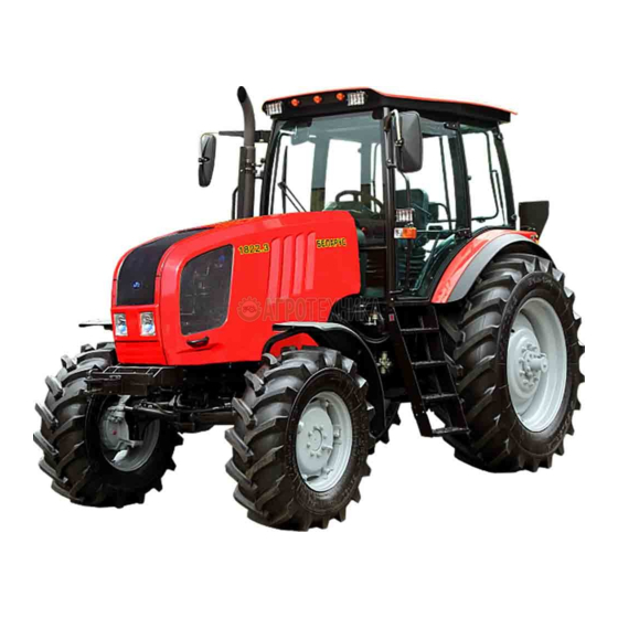
1822.3
Operator's manual
Belarus 1822.3 Operator's Manual
Hide thumbs
1
2
Table Of Contents
3
4
5
6
7
8
9
10
11
12
13
14
15
16
17
18
19
20
21
22
23
24
25
26
27
28
29
30
31
32
33
34
35
36
37
38
39
40
41
42
43
44
45
46
47
48
49
50
51
52
53
54
55
56
57
58
59
60
61
62
63
64
65
66
67
68
69
70
71
72
73
74
75
76
77
78
79
80
81
82
83
84
85
86
87
88
89
90
91
92
93
94
95
96
97
98
99
100
101
102
103
104
105
106
107
108
109
110
111
112
113
114
115
116
117
118
119
120
121
122
123
124
125
126
127
128
129
130
131
132
133
134
135
136
137
138
139
140
141
142
143
144
145
146
147
148
149
150
151
152
153
154
155
156
157
158
159
160
161
162
163
164
165
166
167
168
169
170
171
172
173
174
175
176
177
178
179
180
181
182
183
184
185
186
187
188
189
190
191
192
193
194
195
196
197
198
199
200
201
202
203
204
205
206
207
208
209
210
211
212
213
214
215
216
217
218
219
220
221
222
223
224
225
226
227
228
229
230
231
232
233
234
235
236
237
238
239
240
241
242
243
244
245
246
247
248
249
250
251
252
253
254
255
256
257
258
259
260
261
262
263
264
265
266
267
268
269
270
271
272
273
274
275
276
277
278
279
280
281
282
283
284
285
286
287
288
289
290
291
292
293
294
295
296
297
298
299
300
301
302
303
304
305
306
307
308
309
310
311
312
313
314
315
316
317
318
319
320
321
322
323
324
325
326
327
328
329
330
331
332
333
334
335
336
337
338
339
340
341
342
343
344
345
346
347
348
349
350
351
352
353
354
355
356
357
358
page
of
358
Go
/
358
Contents
Table of Contents
Troubleshooting
Bookmarks
Table of Contents
Table of Contents
1 Tractor Description and Operation
Tractor Assignment
Technical Specifications
Tractor Composition
Vibration Level at Operator's Working Place of Tractor "BELARUS- 1822.3/1822 .3/2022.3/2022 .3
Noise Level at Operator's Working Place of Tractor BELARUS- 1822.3/1822 .3/2022.3/2022 .3
Tractor Marking
Packing
2 Controls and Instruments
Layout of Controls and Instruments of the Tractor
Switches of Instrument Board
Upper Shield Unit of Button Switches
Conditioner Control
Conditioner Control in Conditioning Mode
Conditioner Control in Heating Mode
Cab Ventilation
Instrument Board
Pilot Lamps Unit
Integrated Indicator and Integrated Indicator Control Panel
General Information
Assignment and Operation Principle of Integrated Indicator Gauges
Pilot Lamps of the Integrated Indicator
Description of Testing the Integrated Indicator Performance
Steering
General Information
Switching of Reverse Box Valve on Tractors "BELARUS-1822 .3/2022 .3
Steering Wheel Adjustments
Parking Brake Control
Handle to Kill the Engine
Handle for Fuel Feed Manual Control
Tractor Pedals
Switching of Ranges, Gears and Passes of the Gearbox Reduction Unit
General Information
Tractor Velocity Diagram
Control Panel for Rear Axle DL, FDA and FPTO Drives. Rear Power Takeoff Control
General Information
Indication of the Engaged Pass of the Reduction Unit
Front Power Take-Off Shaft Control
FDA Drive Control
Rear Axle Differential Lock Control
Annunciation of Emergency Oil Temperature in the Hydraulic Lift Linkage
Rear PTO Control
Lift Linkage Controls
General Information on Rules of Rear Lift Linkage Control
RLL Control Panel
Remote Buttons of RLL Control System
Troubleshooting of RLL Electronic Control System
Front Lift Linkage Control
Controlling Sections of the HLL Valve Group (Remote Cylinders)
HLL Pump Control
Cutout Fuses
General Information
Fuses for Electrical Equipment System
Fuses of Electronic Control Systems
Cab Locks and Handles
Cab Door Locks
Side Glass Opening
Rear Screen Opening
Cab Hatch Opening
Seat and Its Adjustments
General Information
Belarus Seat Adjustments
BELARUS Seat Installation for Operation on Reverse
Grammer" Seat Adjustments
Controlling Drive of Transmission Hydraulic System Pump
Controlling Pneumatic System Compressor
Connector Elements of the Electrical Equipment
Socket to Connect Coupled Agricultural Equipment
Connection of Additional Electrical Equipment of Coupled Machines
Reverse Post Controls of BELARUS-1822 .3/2022 .3
Fuel Tank Valve Control
3 Description and Operation of Tractor Constituents
Engine and Its Systems
Engine
General Information
Engine Elements
System of Engine Air Cleaning
System of Charged Air Cooling
Engine Cooling System
Coupling
Coupling Clutch
Peculiarities of Clutch Installation, Dismantling and Adjustment
General Information
Clutch Dismantling
Clutch Installation
Adjustment of Clutch Release Levers
Clutch Drive
Clutch Control Adjustment
Bleeding of the Hydraulic System of Clutch Control
Clutch Check for Purity of Disengagement
Clutch Case
Gearbox
General Information
Mechanism of Engine Start-Up Lock with Range Engaged and Mechanism of FDA Disengagement When Reversing
Gearbox Control Mechanism
General Information
Speed Shifting Mechanism
Range Shifting Mechanism
Mechanism of Switching between the Higher and the Lower Passes of the Gearbox Reduction Unit
Gearbox Control
Reduction Unit Electro-Hydraulic Control
Rear Axle
General Information
Main Drive
Differential
Rear-Axle Drive
Final Drive
Rear Axle Final Drive Adjustment
Differential Lock Mechanism
General Information
Differential Lock Mechanism Adjustment
Rear Power Takeoff Shaft
General Information
Rear PTO Control
Front Power Takeoff Shaft
Brakes
General Information
Service Brake Control of "BELARUS-1822.3/2022.3
Service Brake Adjustment of "BELARUS-1822.3/2022.3
Service Brake Control of "BELARUS-1822 .3/2022 .3
Service Brake Adjustment of "BELARUS-1822 .3/2022 .3
Parking Brake
Parking Brake Adjustment
Pneumatic System
General Information
Single-Line Pneumatic Drive of Trailer Brakes
Double-Line Pneumatic Drive of Trailer Brakes
Combined Pneumatic Drive of Trailer Brakes
General Information
Check and Adjustment of Single-Line and Double-Line Brake Valves of the Pneumatic System
General Information
Check and Adjustment of the Single-Line Brake Valve Actuator of the Pneumatic System
Check and Adjustment of the Double-Line Brake Valve Actuator of the Pneumatic System
Check and Adjustment of Pneumatic System Pressure Regulator
Transmission Hydraulic System
Front Driving Axle
General Information
Central Reduction Unit
Wheel Gear Group
FDA Drive
General Information
Adjustment of FDA Drive Automatic Switch
Electronic System for Rear-Axle Differential Lock Control, Front Driving Axle Drive Control, and Front Power Take off Shaft Control
Rear Axle Differential Lock Control
FDA Drive Control
Front PTO Control
Undercarriage and Tractor Wheels
Hydrostatic Steering Control
General Information
Dosing Pump
Steering Hydraulic Cylinder
HSC Oil Tank
Hydraulic Lift Linkage (HLL)
General Information
Oil Tank
HLL Pump Drive
Valve Group
Installation and Adjustments of Position and Force Sensors of RLL ECS
General Information
Installation and Adjustment of the Position Sensor
Force Sensor Installation
Indication of Emergency States of Hydraulic Lift Linkage
Rear Lift Linkage
General Information
Turnbuckle
Arm
Rear Lift Linkage Electronic Control System
Front Lift Linkage
General Information
Rules of Shifting FLL from Operating Position to Transport Position
Rules for Coupling Agricultural Machines with FLL
All-Purpose Drawbar Hitch
Electrical Equipment
General Information
Heating Plug Operation Principle
Order of Integrated Indicator Programming
Control Panel of Integrated Indicator
Algorithm of Integrated Indicator Programming
Installation and Adjustment of Speed Sensors and RPM Sensor of Rear PTO
Speed Sensor Installation
Installation of Rear PTO RPM Sensor
Cab Air Conditioning and Heating System
Cab
General Information
Cab Installation
Doors
Side Screens
Rear Screen
Outside Mirrors
Roof with Opening Hatch
Marking of Tractor Components
4 Intended Use of Tractor
Safety Measures to be Taken Preparing Tractor for Operation
Tractor Use
Boarding the Tractor
Preparing for Start and Starting the Engine
Tractor Motion Start, GB Shifting
Tractor Stop
Engine Stop
Getting off the Tractor
PTO Use
Selection of Optimal Inner Pressure in Tires Depending on Operational Conditions and Load on Tractor Axles, Instructions for Tire Use
Selection of Optimal Inner Pressure in Tires Depending on Operational Conditions and Load on Tractor Axles
Instructions for Tire Use
Permissible Combination of Front and Rear Tires
Tire Inflation
Rear Wheel Track Formation
Rear Wheel Twinning
Front Wheel Track Formation
Safety Measures to be Taken When Operating the Tractor
General Safety Measures to be Taken When Operating the Tractor
Fire Safety Measures
Tractor Final Assembly and Run-In
Tractor Final Assembly
Technical Maintenance before Tractor Run-In
Tractor Run-In
Technical Maintenance During Tractor Run-In
Technical Maintenance after Tractor Run-In
Actions in Extreme Conditions
5 Coupling of Implements
General Information
Types of Implements Coupled with Tractor "BELARUS
Lift Linkage
General Information
Three-Point Rear Lift Linkage
Three-Point Front Lift Linkage
Drawbar Hitches
General Information
Drawbar Hitch DH-2V
Drawbar Hitch DH- V
Drawbar Hitch DH-2R
Drawbar Hitch DH-1 -01
Drawbar Hitch DH -1
Usage Patterns of Tractor Hydraulic System for Driving of Operated Parts and Other Elements of Unitized Hydraulically Operated Machines and Units
Selection of Implements for Coupling
General Instructions
Methods of Selection of the Implements for Coupling
Calculating Method for Selection of Implements for Coupling
Experimental Method for Selection of Implements for Coupling
Test of Correctness of Composition of the Machine and Tractor Unit
Selection of Ploughs
Power Take-Off Shaft Ends
Determination of PTO Shaft and Cardan Shaft Applicability
Features of Application of PTO Shafts and Cardan Shafts
Ways of Changing of Drawbar Features and Passing Ability of the Tractors
General Information
Ways of Changing of Drawbar Features and Passing Ability of the Tractors
Application of Hinge-Mounted Quick-Detachable Ballast
Filling up the Tires with Water (Solution) for the Purpose of Adhesive Weight
Increasing
Procedure of Filling with Water or Water Solution
Order of Partial Water or Water Solution Drain from the Wheels Tires
Order of Full Water or Water Solution Drain from the Wheels Tires
Selection of the Tires Internal Pressure
Application of Rear Axle Differential Blocking
Doubling of Wheels
Features of the Tractor Application in Special Conditions
Tractor Operation in Areas with Rugged Topography. Possibility of the Tractor Application for Haylage Allocation for Reserve
Application of Substances for the Purpose of Chemical Treatment
Operation in a Forest
Driving on Public Roads and Selection of Speed
Finding of Total Weight, Loads on the Front and Rear Axles, Tires Holding Capacity and Required Minimum Ballast
Choice and Installation of Front Loader
General Information
Safety Measures by Tractor "BELARUS-1822.3/1822 .3/2022.3/2022
Operation with Loader Installed
Information about Mounting Holes
Usage Peculiarities of Special Low-Speed Modification of 2022B.3 - 17/32
6 Maintenance
General Instructions
Providing Access to the Components for Maintenance Services
Providing Access to the Components for Maintenance Service of Tractors with Facing Consisting of the Hood, Mask and Side Pieces
Providing Access to the Components for Maintenance Services of Tractors with Facing Consisting of Hood Only
Maintenance Procedure
Scheduled Maintenance Service Operations
Maintenance Service on a Shift Basis (SBMS) in Every 8 - 10 Hours of Operation or Per Shift
Maintenance Service in Every 125 Hours of Operation
Maintenance Services in Every 250 Hours of Operation
Maintenance Services in Every 500 Hours of Operation
Maintenance Service in Every 1000 Hours of Operation
Maintenance Service in Every 2000 Hours of Operation
Maintenance Service that Does Not Coincide with Intervals of MS-1, 2MS-1, MS-2, MS-3 and Special MS
General Maintenance Services
Seasonal Maintenance Services
Safety Measures While Maintenance Service and Repair Operations
General Safety Requirements
Safety Precautions for Exclusion of Hazardous Situations Related to Accumulator Batteries and a Fuel Tank
Guidelines for Safe Use of Leveling Jacks and Statement of Proper Places for Their Installation
Filling and Lubrication of the Tractor with Fuel and Lubrication Materials
Possible Failures and Instructions for Their Troubleshooting
Possible Engine Failures and Instructions for Their Troubleshooting
Possible Clutch Failures and Instructions for Their Troubleshooting
Possible Failures in the Gearbox and Instructions for Their Troubleshooting
Possible Failures in the Electronic Control System for Rear Axle Differential Lock, Front Driving Axle Drive, Front Power Take off Shaft, GB Reduction Gear and Instructions for Their Troubleshooting
Possible Failures in Rear Axle and Guidelines for Troubleshooting
Possible Failures in Rear Power Take-Off Shaft and Guidelines for Troubleshooting
Possible Failures in Front Power Take-Off Shaft and Guidelines for Troubleshooting
Possible Failures of Brakes and Guidelines for Troubleshooting
Possible Failures in Pneumatic System and Guidelines for Troubleshooting
Possible Failures of Transmission Hydraulic System and Guidelines for Troubleshooting
Possible Failures of FDA and Guidelines for Troubleshooting
Possible Failures of Hydrostatic Steering Control and Guidelines for Troubleshooting
Possible Failures in the Electronic Control System of RLL and Guidelines for Troubleshooting
Possible Failures of the Hydraulic Lift Linkage and Guidelines for Troubleshooting
General Information
Guidelines for Troubleshooting in HLL
Section R-23LS Lowering Valve Disassembly Procedure
Possible Failures in the Electrical Equipment and Guidelines for Troubleshooting
General Information
Search and Elimination of Failures in Electrics Power-Supply
Search and Elimination of Failures in Engine Start-Up System
Search and Elimination of Failures in Lighting Facilities
Search and Elimination of Failures in Air Conditioner Electrics
Search and Elimination of Failures in Operation of Front and Rear Wiper, Windscreen Washer, Acoustic Alarm
Search and Elimination of Failures in Operation of Heating Plugs
Search and Elimination of Failures in Test Instruments Operation Located on the Dashboard
Possible Failures of Air-Conditioning and Cab Heating Systems and Guidelines for Troubleshooting
Advertisement
Quick Links
1
Gearbox
Download this manual
BELARUS
1822.3/1822 .3
2022.3/2022 .3
2022.3-0000010 OM
OPERATOR'S MANUAL
2012
https://tractormanualz.com/
Table of
Contents
Previous
Page
Next
Page
1
2
3
4
5
Advertisement
Table of Contents
Troubleshooting
Remote buttons of RLL control system
49
POSSIBLE FAILURES AND INSTRUCTIONS FOR THEIR TROUBLESHOOTING
297
Possible clutch failures and instructions for their troubleshooting
301
Possible failures in the gearbox and instructions for their troubleshooting
304
Possible failures in the electronic control system for rear axle differential lock, front driving axle drive, front power take off shaft, GB reduction gear and instructions for their troubleshooting
305
Possible failures in rear axle and guidelines for troubleshooting
307
Possible failures in front power take-off shaft and guidelines for troubleshooting
308
Possible failures of brakes and guidelines for troubleshooting
309
Possible failures in pneumatic system and guidelines for troubleshooting
312
Possible failures of transmission hydraulic system and guidelines for troubleshooting
314
Possible failures of FDA and guidelines for troubleshooting
315
Possible failures of hydrostatic steering control and guidelines for troubleshooting
318
Possible failures in the electronic control system of RLL and guidelines for troubleshooting
321
Possible failures of the hydraulic lift linkage and guidelines for troubleshooting
327
Possible failures in the electrical equipment and guidelines for troubleshooting
330
Possible failures of air-conditioning and cab heating systems and guidelines for troubleshooting
344
Need help?
Do you have a question about the 1822.3 and is the answer not in the manual?
Ask a question
Questions and answers
Related Manuals for Belarus 1822.3
Tractor Belarus 1221.2 Operator's Manual
(295 pages)
Tractor Belarus 1221.3 Operator's Manual
(295 pages)
Tractor Belarus 1221B.2 Operator's Manual
(295 pages)
Tractor Belarus 1025 2008 Operation Manual
(206 pages)
Tractor Belarus BELARUS-1523 Operating Manual
(312 pages)
Tractor Belarus 1021 Operating Manual
(209 pages)
Tractor Belarus 1523.5 Operator's Manual
(210 pages)
Tractor Belarus 1523.6 Operator's Manual
(223 pages)
Tractor Belarus 1221.6 Operator's Manual
(193 pages)
Tractor Belarus 1220.6 Operator's Manual
(207 pages)
Tractor Belarus 1025.6 Operator's Manual
(178 pages)
Tractor Belarus 80X Information Bulletin
(26 pages)
Tractor Belarus 3522.5 Operator's Manual
(340 pages)
Tractor Belarus 80.1 Series Operation And Service Manual
(143 pages)
Tractor Belarus 920.4 Operating Manual
With engine d-245.43s3a/d-245.5s3a (58 pages)
Tractor Belarus 922.6 Operator's Manual
(195 pages)
This manual is also suitable for:
1822b.3
2022.3
2022b.3
Table of Contents
Print
Rename the bookmark
Delete bookmark?
Delete from my manuals?
Login
Sign In
OR
Sign in with Facebook
Sign in with Google
Upload manual
Upload from disk
Upload from URL


Need help?
Do you have a question about the 1822.3 and is the answer not in the manual?
Questions and answers